

Page 1
LASERJET PRO CP1520
COLOR PRINTER SERIES
Service Manual
Page 2

Copyright and License
Trademark Credits
© 2010 Copyright Hewlett-Packard
Development Company, L.P.
Reproduction, adaptation, or translation
without prior written permission is
prohibited, except as allowed under the
copyright laws.
The information contained herein is subject
to change without notice.
The only warranties for HP products and
services are set forth in the express
warranty statements accompanying such
products and services. Nothing herein
should be construed as constituting an
additional warranty. HP shall not be liable
for technical or editorial errors or omissions
contained herein.
Part number: CE873-90934
Edition 1, 9/2010
Microsoft®, Windows®, Windows® XP, and
Windows Vista® are U.S. registered
trademarks of Microsoft Corporation.
ENERGY STAR and the ENERGY STAR
mark are registered U.S. marks.
Page 3

Conventions used in this guide
TIP: Tips provide helpful hints or shortcuts.
NOTE: Notes provide important information to explain a concept or to complete a task.
CAUTION: Cautions indicate procedures that you should follow to avoid losing data or damaging
the product.
WARNING! Warnings alert you to specific procedures that you should follow to avoid personal
injury, catastrophic loss of data, or extensive damage to the product.
ENWW iii
Page 4

Table of contents
1 Removal and replacement ............................................................................................................................. 1
Introduction ........................................................................................................................................... 2
Removal and replacement strategy ...................................................................................................... 2
Electrostatic discharge ......................................................................................................................... 3
Required tools ...................................................................................................................................... 3
Service approach ................................................................................................................................. 3
Before performing service .................................................................................................... 3
After performing service ....................................................................................................... 4
Post-service test .................................................................................................................. 4
Print-quality test .................................................................................................. 4
Parts removal order ............................................................................................................. 4
Removal and replacement procedures ................................................................................................ 5
Remove the print cartridges ................................................................................................. 5
Rollers .................................................................................................................................. 6
Pickup roller ........................................................................................................ 6
Separation roller .................................................................................................. 7
Transfer roller ...................................................................................................................... 8
Feed assembly .................................................................................................................... 9
External panels, covers, and doors ................................................................................... 10
Right cover ........................................................................................................ 10
Left cover .......................................................................................................... 13
Front door and Tray 1 door ............................................................................... 15
Control-panel module ........................................................................................ 19
Rear-side cover ................................................................................................. 21
Rear-upper cover .............................................................................................. 22
Rear door and rear-lower cover ........................................................................ 23
Top cover .......................................................................................................... 25
Internal assemblies ............................................................................................................ 27
Main motor ........................................................................................................ 27
Fuser motor ....................................................................................................... 29
Intermediate transfer belt (ITB) ......................................................................... 30
Reinstall the ITB ............................................................................... 35
DC controller PCA ............................................................................................. 37
Special consideration ....................................................................... 37
ENWW v
Page 5

Remove the DC controller PCA ........................................................ 37
Formatter PCA .................................................................................................. 40
Special consideration ....................................................................... 40
Remove the formatter PCA .............................................................. 40
Wireless PCA .................................................................................................... 42
Power supply (high-voltage) .............................................................................. 43
Power supply (low-voltage) ............................................................................... 47
Power supply (fuser) ......................................................................................... 53
Fuser ................................................................................................................. 56
2 Solve problems ............................................................................................................................................. 59
Solve problems checklist .................................................................................................................... 60
Menu map .......................................................................................................................................... 61
Troubleshooting process .................................................................................................................... 62
Pre-troubleshooting checklist ............................................................................................. 62
Power-on checks ............................................................................................................... 64
Tools for troubleshooting .................................................................................................................... 65
Diagrams ........................................................................................................................... 65
Plug/jack locations ............................................................................................ 65
Locations of major components ........................................................................ 66
General timing charts ........................................................................................ 68
General circuit diagram ..................................................................................... 69
Use HP ToolboxFX ............................................................................................................ 70
View the HP Color LaserJet CP1520 Series Toolbox ....................................... 70
HP ToolboxFX sections ..................................................................................... 71
Status ............................................................................................... 71
Event log ........................................................................................... 71
Help .................................................................................................. 71
System Settings ................................................................................ 71
Print Settings .................................................................................... 74
Network Settings .............................................................................. 74
Shop for Supplies ............................................................................. 74
Other Links ....................................................................................... 75
Internal print-quality test pages .......................................................................................... 75
Interpret the Print Quality Page ......................................................................... 75
Clean the product .............................................................................................. 76
Configuration page ............................................................................................ 76
Print-quality troubleshooting tools ...................................................................................... 77
Repetitive image defects ................................................................................... 77
Calibrate the product to align the colors ............................................................ 77
Control panel menus .......................................................................................................... 78
Reports menu .................................................................................................... 78
Quick Forms menu ............................................................................................ 79
vi ENWW
Page 6

System Setup menu .......................................................................................... 79
Service menu .................................................................................................... 82
Network Setup menu ......................................................................................... 83
Interpret control panel messages ...................................................................................... 84
Control panel message types ............................................................................ 84
Control panel messages ................................................................................... 84
Paper feeds incorrectly or becomes jammed ..................................................................................... 95
The product does not pick up paper .................................................................................. 95
The product picks up multiple sheets of paper .................................................................. 95
Prevent paper jams ............................................................................................................ 95
Clear jams .......................................................................................................................... 96
Jam locations .................................................................................................... 96
Jam in Tray 1 .................................................................................................... 97
Jam in Tray 2 .................................................................................................... 99
Jam in the fuser area ...................................................................................... 100
Jam in the output bin ....................................................................................... 101
Solve image quality problems .......................................................................................................... 102
Use the correct paper type setting in the printer driver .................................................... 102
Change the paper type setting for Windows ................................................... 102
Change the paper type setting for Mac ........................................................... 102
Adjust color settings in the printer driver .......................................................................... 103
Change the color theme for a print job ............................................................ 103
Change the color options ................................................................................ 103
Use paper that meets HP specifications .......................................................................... 104
Print a cleaning page ....................................................................................................... 105
Calibrate the product to align the colors .......................................................................... 105
Check the print cartridges ................................................................................................ 105
Print the Supplies Status page ........................................................................ 106
Inspect the print cartridge for damage ............................................................ 106
Repeating defects ........................................................................................... 107
Use the printer driver that best meets your printing needs .............................................. 107
Clean the product ............................................................................................................................. 109
The product does not print or it prints slowly .................................................................................... 110
The product does not print ............................................................................................... 110
The product prints slowly ................................................................................................. 110
Solve connectivity problems ............................................................................................................. 111
Solve direct-connect problems ........................................................................................ 111
Solve network problems .................................................................................................. 111
Poor physical connection ................................................................................ 111
The computer is using the incorrect IP address for the product ...................... 111
The computer is unable to communicate with the product .............................. 112
The product is using incorrect link and duplex settings for the network .......... 112
New software programs might be causing compatibility problems ................. 112
The computer or workstation might be set up incorrectly ................................ 112
ENWW vii
Page 7

The product is disabled, or other network settings are incorrect ..................... 112
Service mode functions .................................................................................................................... 113
Service menu ................................................................................................................... 113
Service menu settings ..................................................................................... 113
Restore the factory-set defaults ...................................................................... 113
Secondary service menu ................................................................................................. 113
Open the secondary service menu ................................................................. 113
Secondary service menu structure .................................................................. 114
Engine resets ................................................................................................................... 114
Engine test page ............................................................................................. 114
Cold reset ........................................................................................................ 115
NVRAM initialization ........................................................................................ 115
Product updates ............................................................................................................................... 115
3 Parts and diagrams ..................................................................................................................................... 117
Order parts by authorized service providers .................................................................................... 118
Order replacement parts .................................................................................................. 118
Related documentation and software .............................................................................. 118
Supplies part numbers ..................................................................................................... 118
Whole-unit replacement part numbers ............................................................................. 118
How to use the parts lists and diagrams .......................................................................................... 120
Assembly locations ........................................................................................................................... 121
Base product (no optional trays or accessories) .............................................................. 121
Covers, panels, and doors ............................................................................................................... 122
Internal assemblies .......................................................................................................................... 124
Alphabetical parts list ....................................................................................................................... 134
Numerical parts list ........................................................................................................................... 137
Appendix A Service and support ................................................................................................................. 141
Hewlett-Packard limited warranty statement .................................................................................... 142
HP's Premium Protection Warranty: LaserJet print cartridge limited warranty statement ................ 143
Data stored on the print cartridge ..................................................................................................... 144
End User License Agreement .......................................................................................................... 145
OpenSSL .......................................................................................................................................... 147
Customer support ............................................................................................................................. 148
Repack the product .......................................................................................................................... 149
Appendix B Product specifications ............................................................................................................. 151
Physical specifications ..................................................................................................................... 152
Power consumption, electrical specifications, and acoustic emissions ............................................ 152
Environmental specifications ............................................................................................................ 152
viii ENWW
Page 8

Appendix C Regulatory information ............................................................................................................ 153
FCC regulations ............................................................................................................................... 154
Environmental product stewardship program ................................................................................... 155
Protecting the environment .............................................................................................. 155
Ozone production ............................................................................................................ 155
Power consumption ......................................................................................................... 155
Paper use ........................................................................................................................ 155
Plastics ............................................................................................................................ 155
HP LaserJet print supplies ............................................................................................... 155
Return and recycling instructions ..................................................................................... 156
United States and Puerto Rico ........................................................................ 156
Multiple returns (more than one cartridge) ..................................... 156
Single returns ................................................................................. 156
Shipping .......................................................................................... 156
Non-U.S. returns ............................................................................................. 156
Paper ............................................................................................................................... 157
Material restrictions .......................................................................................................... 157
Disposal of waste equipment by users in private households in the European Union .... 157
Chemical substances ....................................................................................................... 157
Material Safety Data Sheet (MSDS) ................................................................................ 157
For more information ....................................................................................................... 158
Declaration of conformity .................................................................................................................. 159
Declaration of Conformity (wireless models) .................................................................................... 161
Safety statements ............................................................................................................................. 163
Laser safety ..................................................................................................................... 163
Canadian DOC regulations .............................................................................................. 163
VCCI statement (Japan) .................................................................................................. 163
Power cord instructions ................................................................................................... 163
Power cord statement (Japan) ......................................................................................... 163
EMC statement (Korea) ................................................................................................... 163
Laser statement for Finland ............................................................................................. 164
GS statement (Germany) ................................................................................................. 164
Substances Table (China) ............................................................................................... 165
Restriction on Hazardous Substances statement (Turkey) ............................................. 165
Additional statements for wireless products ..................................................................................... 166
FCC compliance statement—United States .................................................................... 166
Australia statement .......................................................................................................... 166
Brazil ANATEL statement ................................................................................................ 166
Canadian statements ....................................................................................................... 166
European Union regulatory notice ................................................................................... 166
Notice for use in France ................................................................................................... 167
Notice for use in Russia ................................................................................................... 167
Korean statement ............................................................................................................ 167
Taiwan statement ............................................................................................................ 167
ENWW ix
Page 9

Index ................................................................................................................................................................. 169
x ENWW
Page 10

List of tables
Table 2-1 Major components ............................................................................................................................ 66
Table 2-2 Repetitive image defects .................................................................................................................. 77
Table 2-3 Secondary Service menu ............................................................................................................... 114
Table 3-1 Order parts, accessories, and supplies .......................................................................................... 118
Table 3-2 Related documentation and software ............................................................................................ 118
Table 3-3 Supplies part numbers ................................................................................................................... 118
Table 3-4 Whole-unit replacement part numbers ........................................................................................... 118
Table 3-5 Base product .................................................................................................................................. 121
Table 3-6 Covers, panels, and doors ............................................................................................................. 123
Table 3-7 Internal components (1 of 4) .......................................................................................................... 125
Table 3-8 Internal components (2 of 4) .......................................................................................................... 127
Table 3-9 Internal components (3 of 4) .......................................................................................................... 129
Table 3-10 Internal components (4 of 4) ........................................................................................................ 131
Table 3-11 PCA location ................................................................................................................................ 133
Table 3-12 Alphabetical parts list ................................................................................................................... 134
Table 3-13 Numerical parts list ....................................................................................................................... 137
Table B-1 Physical specifications ................................................................................................................... 152
Table B-2 Operating-environment specifications ........................................................................................... 152
ENWW xi
Page 11

List of figures
Figure 1-1 Phillips and Pozidriv screwdriver comparison ................................................................................... 3
Figure 1-2 Parts-removal order .......................................................................................................................... 4
Figure 1-3 Remove the print cartridge ................................................................................................................ 5
Figure 1-4 Remove the pickup roller .................................................................................................................. 6
Figure 1-5 Remove the separation roller (1 of 2) ............................................................................................... 7
Figure 1-6 Remove the separation roller (2 of 2) ............................................................................................... 8
Figure 1-7 Remove the transfer roller (1 of 3) .................................................................................................... 8
Figure 1-8 Remove the transfer roller (2 of 3) .................................................................................................... 9
Figure 1-9 Remove the transfer roller (3 of 3) .................................................................................................... 9
Figure 1-10 Remove the feed assembly (1 of 2) .............................................................................................. 10
Figure 1-11 Remove the feed assembly (2 of 2) .............................................................................................. 10
Figure 1-12 Remove the right cover (1 of 4) .................................................................................................... 11
Figure 1-13 Remove the right cover (2 of 4) .................................................................................................... 11
Figure 1-14 Remove the right cover (3 of 4) .................................................................................................... 12
Figure 1-15 Remove the right cover (4 of 4) .................................................................................................... 12
Figure 1-16 Remove the left cover (1 of 4) ....................................................................................................... 13
Figure 1-17 Remove the left cover (2 of 4) ....................................................................................................... 13
Figure 1-18 Remove the left cover (3 of 4) ....................................................................................................... 14
Figure 1-19 Remove the left cover (4 of 4) ....................................................................................................... 14
Figure 1-20 Remove the front door and Tray 1 door (1 of 7) ........................................................................... 15
Figure 1-21 Remove the front door and Tray 1 door (2 of 7) ........................................................................... 15
Figure 1-22 Remove the front door and Tray 1 door (3 of 7) ........................................................................... 16
Figure 1-23 Remove the front door and Tray 1 door (4 of 7) ........................................................................... 16
Figure 1-24 Remove the front door and Tray 1 door (5 of 7) ........................................................................... 17
Figure 1-25 Remove the front door and Tray 1 door (6 of 7) ........................................................................... 17
Figure 1-26 Remove the front door and Tray 1 door (7 of 7) ........................................................................... 18
Figure 1-27 Remove the control-panel module (1 of 3) ................................................................................... 19
Figure 1-28 Remove the control-panel module (2 of 3) ................................................................................... 19
Figure 1-29 Remove the control-panel module (3 of 3) ................................................................................... 20
Figure 1-30 Remove the rear-side cover (1 of 2) ............................................................................................. 21
Figure 1-31 Remove the rear-side cover (2 of 2) ............................................................................................. 21
Figure 1-32 Remove the rear-upper cover (1 of 2) ........................................................................................... 22
Figure 1-33 Remove the rear-upper cover (2 of 2) ........................................................................................... 22
Figure 1-34 Remove the rear door and rear-lower cover (1 of 4) .................................................................... 23
ENWW xiii
Page 12

Figure 1-35 Remove the rear door and rear-lower cover (2 of 4) .................................................................... 23
Figure 1-36 Remove the rear door and rear-lower cover (3 of 4) .................................................................... 24
Figure 1-37 Remove the rear door and rear-lower cover (4 of 4) .................................................................... 24
Figure 1-38 Remove the top cover (1 of 4) ...................................................................................................... 25
Figure 1-39 Remove the top cover (2 of 4) ...................................................................................................... 26
Figure 1-40 Remove the top cover (3 of 4) ...................................................................................................... 26
Figure 1-41 Remove the top cover (4 of 4) ...................................................................................................... 27
Figure 1-42 Remove the main motor (1 of 2) ................................................................................................... 27
Figure 1-43 Remove the main motor (2 of 2) ................................................................................................... 28
Figure 1-44 Remove the fuser motor (1 of 2) ................................................................................................... 29
Figure 1-45 Remove the fuser motor (2 of 2) ................................................................................................... 29
Figure 1-46 Remove the ITB (1 of 9) ................................................................................................................ 30
Figure 1-47 Remove the ITB (2 of 9) ................................................................................................................ 30
Figure 1-48 Remove the ITB (3 of 9) ................................................................................................................ 31
Figure 1-49 Remove the ITB (4 of 9) ................................................................................................................ 31
Figure 1-50 Remove the ITB (5 of 9) ................................................................................................................ 32
Figure 1-51 Remove the ITB (6 of 9) ................................................................................................................ 32
Figure 1-52 Remove the ITB (7 of 9) ................................................................................................................ 33
Figure 1-53 Remove the ITB (8 of 9) ................................................................................................................ 33
Figure 1-54 Remove the ITB (9 of 9) ................................................................................................................ 34
Figure 1-55 Reinstall the ITB (1 of 2) ............................................................................................................... 35
Figure 1-56 Reinstall the ITB (2 of 2) ............................................................................................................... 36
Figure 1-57 Remove the DC controller PCA (1 of 3) ........................................................................................ 38
Figure 1-58 Remove the DC controller PCA (2 of 3) ........................................................................................ 38
Figure 1-59 Remove the DC controller PCA (3 of 3) ........................................................................................ 39
Figure 1-60 Remove the formatter PCA (1 of 2) .............................................................................................. 41
Figure 1-61 Remove the formatter PCA (2 of 2) .............................................................................................. 41
Figure 1-62 Remove the wireless PCA ............................................................................................................ 42
Figure 1-63 Remove the power supply (high-voltage; 1 of 6) .......................................................................... 43
Figure 1-64 Remove the power supply (high-voltage; 2 of 6) .......................................................................... 44
Figure 1-65 Remove the power supply (high-voltage; 3 of 6) .......................................................................... 44
Figure 1-66 Remove the power supply (high-voltage; 4 of 6) .......................................................................... 45
Figure 1-67 Remove the power supply (high-voltage; 5 of 6) .......................................................................... 45
Figure 1-68 Remove the power supply (high-voltage; 6 of 6) .......................................................................... 46
Figure 1-69 Reinstall the power supply (high voltage) ..................................................................................... 46
Figure 1-70 Remove the power supply (low-voltage; 1 of 10) .......................................................................... 47
Figure 1-71 Remove the power supply (low-voltage; 2 of 10) .......................................................................... 48
Figure 1-72 Remove the power supply (low-voltage; 3 of 10) .......................................................................... 48
Figure 1-73 Remove the power supply (low-voltage; 4 of 10) .......................................................................... 49
Figure 1-74 Remove the power supply (low-voltage; 5 of 10) .......................................................................... 49
Figure 1-75 Remove the power supply (low-voltage; 6 of 10) .......................................................................... 50
Figure 1-76 Remove the power supply (low-voltage; 7 of 10) ....................................................................
Fi
Figure 1-78 Remove the power supply (low-voltage; 9 of 10) .......................................................................... 51
-77 Remove the power supply (low-voltage; 8 of 10) .......................................................................... 51
gure 1
...... 50
xiv ENWW
Page 13

Figure 1-79 Remove the power supply (low-voltage; 10 of 10) ........................................................................ 52
Figure 1-80 Remove the power supply (fuser; 1 of 5) ...................................................................................... 53
Figure 1-81 Remove the power supply (fuser; 2 of 5) ...................................................................................... 53
Figure 1-82 Remove the power supply (fuser; 3 of 5) ...................................................................................... 54
Figure 1-83 Remove the power supply (fuser; 4 of 5) ...................................................................................... 54
Figure 1-84 Remove the power supply (fuser; 5 of 5) ...................................................................................... 55
Figure 1-85 Remove the fuser (1 of 4) ............................................................................................................. 56
Figure 1-86 Remove the fuser (2 of 4) ............................................................................................................. 57
Figure 1-87 Remove the fuser (3 of 4) ............................................................................................................. 57
Figure 1-88 Remove the fuser (4 of 4) ............................................................................................................. 58
Figure 2-1 Major components .......................................................................................................................... 66
Figure 2-2 Timing diagram ............................................................................................................................... 68
Figure 2-3 Circuit diagram ................................................................................................................................ 69
Figure 3-1 Base product (no optional trays or accessories) ........................................................................... 121
Figure 3-2 Covers, panels, and doors ............................................................................................................ 122
Figure 3-3 Internal components (1 of 4) ......................................................................................................... 124
Figure 3-4 Internal components (2 of 4) ......................................................................................................... 126
Figure 3-5 Internal components (3 of 4) ......................................................................................................... 128
Figure 3-6 Internal components (4 of 4) ......................................................................................................... 130
Figure 3-7 PCA location ................................................................................................................................. 132
ENWW xv
Page 14

1 Removal and replacement
Introduction
●
Removal and replacement strategy
●
Electrostatic discharge
●
Required tools
●
Service approach
●
Removal and replacement procedures
●
ENWW 1
Page 15

Introduction
This chapter describes the removal and replacement of field-replaceable units (FRUs) only.
Replacing FRUs is generally the reverse of removal. Occasionally, notes and tips are included to
provide directions for difficult or critical replacement procedures.
HP does not support repairing individual subassemblies or troubleshooting to the component level.
Note the length, diameter, color, type, and location of each screw. Be sure to return each screw to its
original location during reassembly.
Incorrectly routed or loose wire harnesses can interfere with other internal components and can
become damaged or broken. Frayed or pinched harness wires can be difficult to find. When replacing
wire harnesses, always use the provided wire loops, lance points, or wire-harness guides and
retainers.
Removal and replacement strategy
WARNING! Turn the product off, wait 5 seconds, and then remove the power cord before
attempting to service the product. If this warning is not followed, severe injury can result, in addition to
damage to the product. The power must be on for certain functional checks during troubleshooting.
However, disconnect the power supply during parts removal.
Never operate or service the product with the protective cover removed from the laser/scanner
assembly. The reflected beam, although invisible, can damage your eyes.
The sheet-metal parts can have sharp edges. Be careful when handling sheet-metal parts.
CAUTION: Do not bend or fold the flat flexible cables (FFCs) during removal or installation. Also, do
not straighten pre-folds in the FFCs. You must fully seat all FFCs in their connectors. Failure to fully
seat an FFC into a connector can cause a short circuit in a PCA.
NOTE: To install a self-tapping screw, first turn it counterclockwise to align it with the existing thread
pattern, and then carefully turn it clockwise to tighten. Do not overtighten. If a self-tapping screw-hole
becomes stripped, repair the screw-hole or replace the affected assembly.
TIP: For clarity, some photos in this chapter show components removed that would not be removed
to service the product. If necessary, remove the components listed at the beginning of a procedure
before proceeding to service the product.
2 Chapter 1 Removal and replacement ENWW
Page 16
Electrostatic discharge
CAUTION: Some parts are sensitive to electrostatic discharge (ESD). Look for the ESD
reminder when removing product parts. Always perform service work at an ESD-protected
workstation or mat, or use an ESD strap. If an ESD workstation, mat, or strap is not available, ground
yourself by touching the sheet-metal chassis before touching an ESD-sensitive part.
Protect the ESD-sensitive parts by placing them in ESD pouches when they are out of the product.
Required tools
#2 Phillips screwdriver with a magnetic tip and a 152-mm (6-in) shaft length
●
Small flat-blade screwdriver
●
Needle-nose pliers
●
ESD mat or ESD strap (if one is available)
●
Penlight (optional)
●
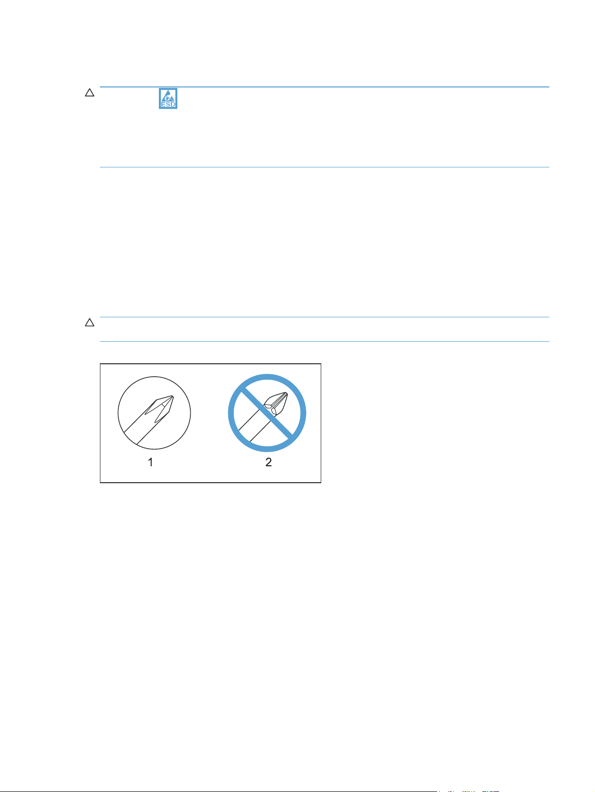
CAUTION: Always use a Phillips screwdriver (callout 1). Do not use a Pozidriv screwdriver
(callout 2) or any motorized screwdriver. These can damage screws or screw threads.
Figure 1-1 Phillips and Pozidriv screwdriver comparison
Service approach
Before performing service
Remove all paper from the product.
●
Turn off the power using the power switch.
●
Unplug the power cable and interface cable or cables.
●
Place the product on an ESD workstation or mat, or use an ESD strap (if one is available). If an
●
ESD workstation, mat, or strap is not available, ground yourself by touching the sheet-metal
chassis before touching an ESD-sensitive part.
Remove the print cartridge.
●
ENWW Electrostatic discharge 3
Page 17

After performing service
● Plug in the power cable.
● Reinstall the print cartridge.
Load paper in the product.
●
Post-service test
Perform the following test to verify that the repair or replacement was successful.
Print-quality test
1. Verify that you have completed the necessary reassembly steps.
2. Make sure that the tray contains clean, unmarked paper.
3. Attach the power cord and interface cable or interface cables, and then turn on the product.
4. Verify that the expected startup sounds occur.
5. Print a configuration page, and then verify that the expected printing sounds occur.
6. Print a demo page, and then verify that the print quality is as expected.
7. Send a print job from the host computer, and then verify that the output meets expectations.
8. Clean the outside of the product with a damp cloth.
Parts removal order
Use the following diagram to determine which parts must be removed before removing other parts.
Figure 1-2 Parts-removal order
Component Remove
Print cartridges
Pickup roller
Separation roller
Transfer roller
Feed assembly
Right cover
Left cover
Front door and Tray 1 door
Control-panel module
Rear-side cover
Rear-upper cover
Rear door and rear-lower cover
Top cover
Main motor
Fuser motor
Intermediate transfer belt
DC controller PCA
Formatter PCA
Wireless PCA
Power supply (high-voltage)
Power supply (low-voltage)
Power supply (fuser)
Fuser
Cartridge drawer
Tray 2
Tray 2
Tray 2
Tray 2
Right cover
Right cover
Right cover
Right cover
Right cover
Right cover
Right cover
Right cover
Right cover
Right cover
Right cover
Right cover
Right cover
Right cover
Right cover
Remove
Left cover
Left cover
Left cover
Left cover
Left cover
Control-panel module
Left cover
Left cover
Left cover
Left cover
Remove Remove
Rear-side cover
Rear-side cover
Control panel module Rear-side cover
Rear-side cover
Control panel module
Rear-side cover
Control panel module
Rear-side cover
Rear-side cover
Control panel module
Rear-side cover
Rear-upper cover
Rear-side cover
Rear door and
rear-door lower cover
Rear door and
rear-door lower cover
Rear-side cover
Remove
Rear-upper cover
Rear-upper cover
Top cover
Rear-upper cover
Rear-upper cover Rear door and
Remove Remove
rear-door lower cover
Top cover
4 Chapter 1 Removal and replacement ENWW
Page 18
Removal and replacement procedures
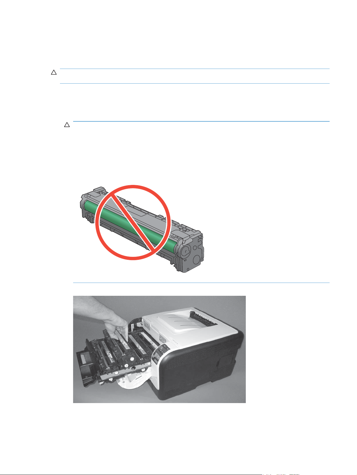
Remove the print cartridges
CAUTION: If toner gets on your clothing, wipe it off with a dry cloth and wash the clothing in cold
water. Hot water sets toner into the fabric.
1. Open the front door and pull out the print-cartridge drawer.
2. Grasp the handle on the print cartridge, and then pull the cartridge straight up to remove it.
Repeat this step for the remaining print cartridges.
CAUTION: Do not touch the imaging drum on the bottom of the print cartridge. Finger prints on
the imaging drum can cause print-quality problems.
Do not allow the image drum to contact any surface when the cartridges are set down. Protect
the image drum at all times. Dust and debris can stick to the drum and cause print-quality
problems.
Figure 1-3 Remove the print cartridge
3. Close the print-cartridge and front doors.
ENWW Removal and replacement procedures 5
Page 19
Rollers
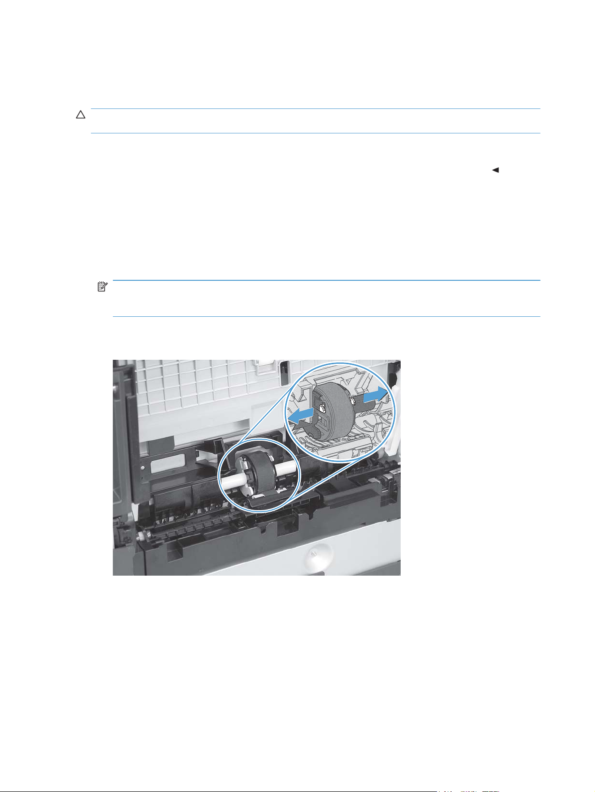
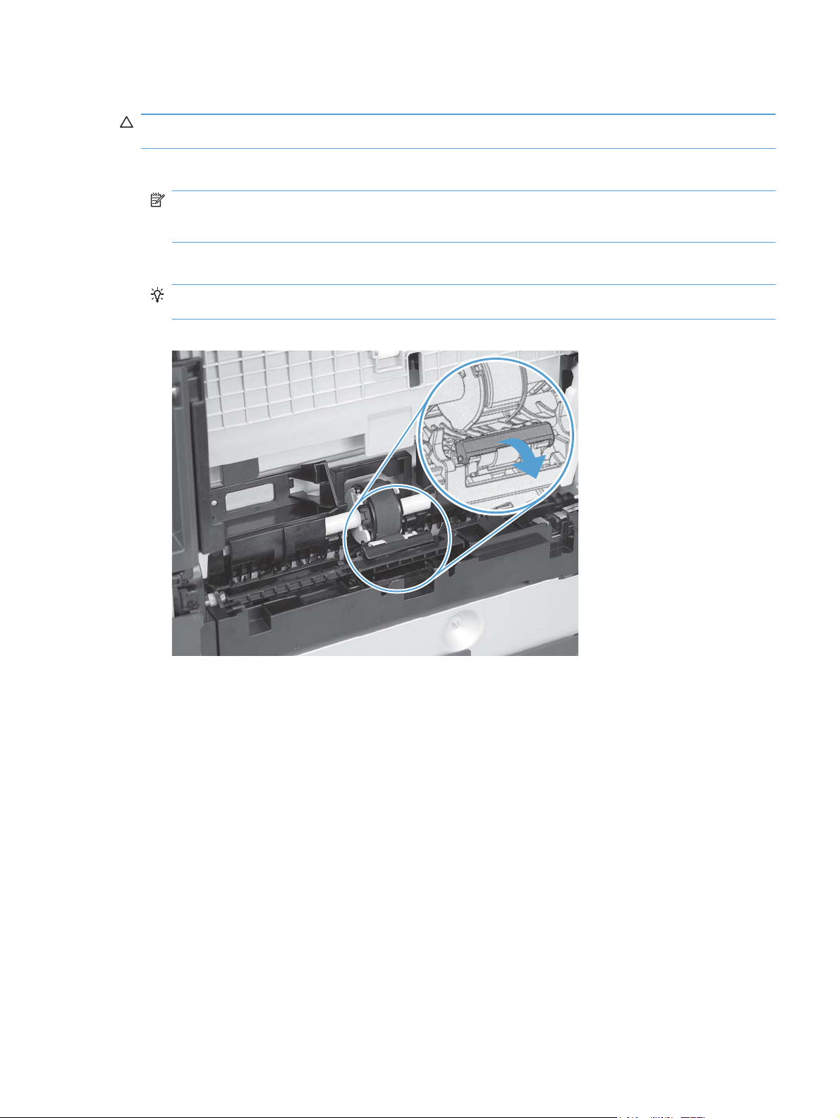
Pickup roller
CAUTION: Do not touch the spongy roller surface unless you are going to replace the roller. Skin
oils on the roller can cause paper pickup problems.
1. Use the following procedure to rotate the roller into the position required to remove it.
Open the Secondary Service menu by pressing and holding both the Left arrow (
●
Cancel button simultaneously.
Use the arrow buttons to select Pick roller, and then press the OK button.
●
Press the OK button again to confirm that you want the pick roller to rotate.
●
Turn the power off.
●
2. Remove Tray 2, and then carefully place the product front-side up.
NOTE: Debris can scratch or damage the back of the product. Before you place the product
front-side up, remove any debris from the work surface. If possible, set the product on a clean,
dry cloth to prevent scratching and damage.
3. Release the two white plastic locking tabs and remove the pickup roller.
Figure 1-4 Remove the pickup roller
) and the
6 Chapter 1 Removal and replacement ENWW
Page 20
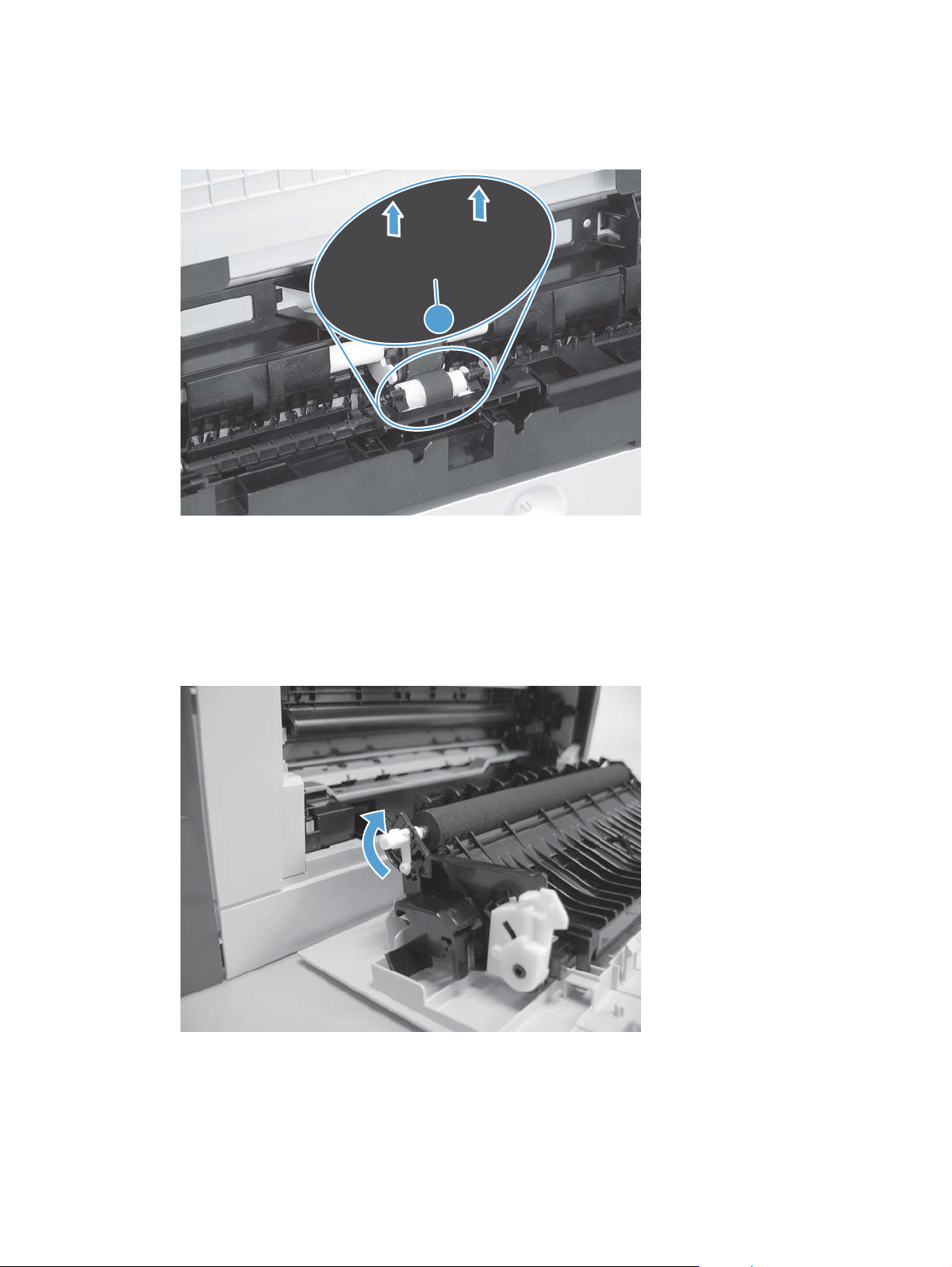
Separation roller
CAUTION: Do not touch the spongy roller surface unless you are going to replace the roller. Skin
oils on the roller can cause paper pickup problems.
1. Remove paper tray (if installed), and then carefully place the product front-side up.
NOTE: Debris can scratch or damage the back of the product. Before you place the product
front-side up, remove any debris from the work surface. If possible, set the product on a clean,
dry cloth to prevent scratching and damage.
2. Carefully release the roller cover and rotate it down and away from the roller.
Reinstallation tip Make sure that this cover snaps into place over the roller when the roller
and holder are reinstalled.
Figure 1-5 Remove the separation roller (1 of 2)
ENWW Removal and replacement procedures 7
Page 21
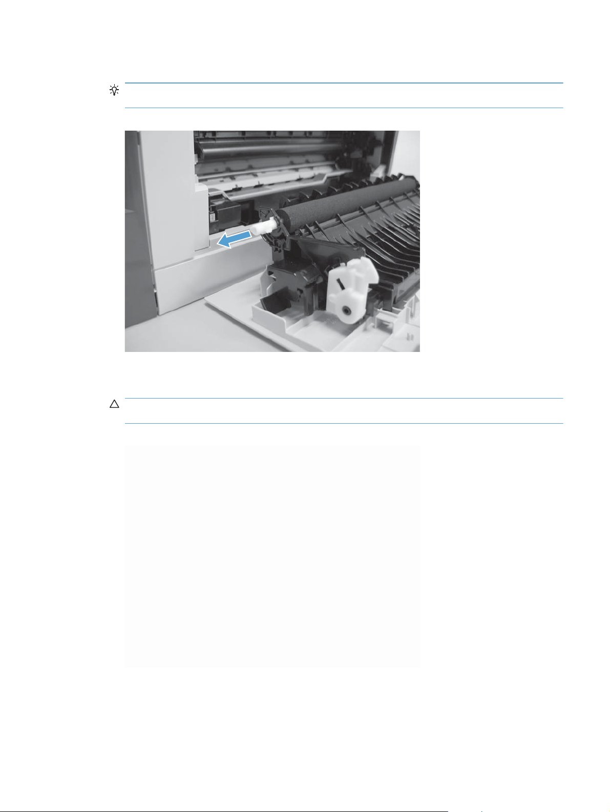
3. Use a small flat blade screwdriver to gently pry up on the roller and holder assembly (callout 1)
to remove the roller and holder assembly.
Figure 1-6 Remove the separation roller (2 of 2)
Transfer roller
1
1. Open the rear door.
2. Release the retainer clip and then rotate it until the pin on the clip aligns with the slot in the
mounting bracket.
Figure 1-7 Remove the transfer roller (1 of 3)
8 Chapter 1 Removal and replacement ENWW
Page 22
3. Remove the clip. Repeat these steps for the remaining retainer clip.
TIP: One of the clips is made from a black conductive plastic. Make sure that the clips are
reinstalled on the side of the transfer roller that they are removed from.
Figure 1-8 Remove the transfer roller (2 of 3)
4. Slide the roller to one side to disengage the roller shaft from the mounting bracket, and then
remove the transfer roller.
CAUTION: Do not touch the black sponge portion of the roller. Skin oils can cause print-quality
problems.
Figure 1-9 Remove the transfer roller (3 of 3)
Feed assembly
1. Open the rear door.
ENWW Removal and replacement procedures 9
Page 23
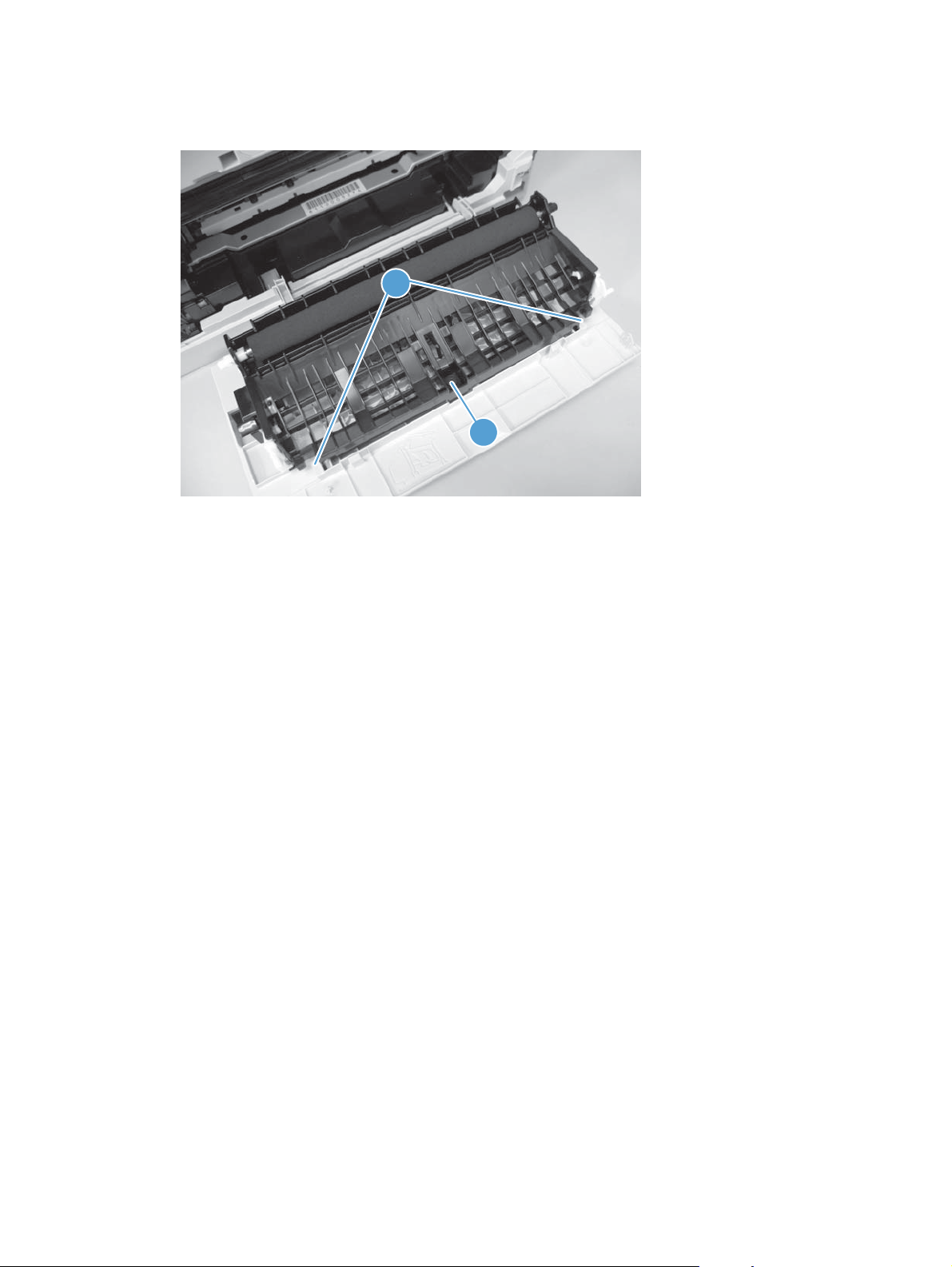
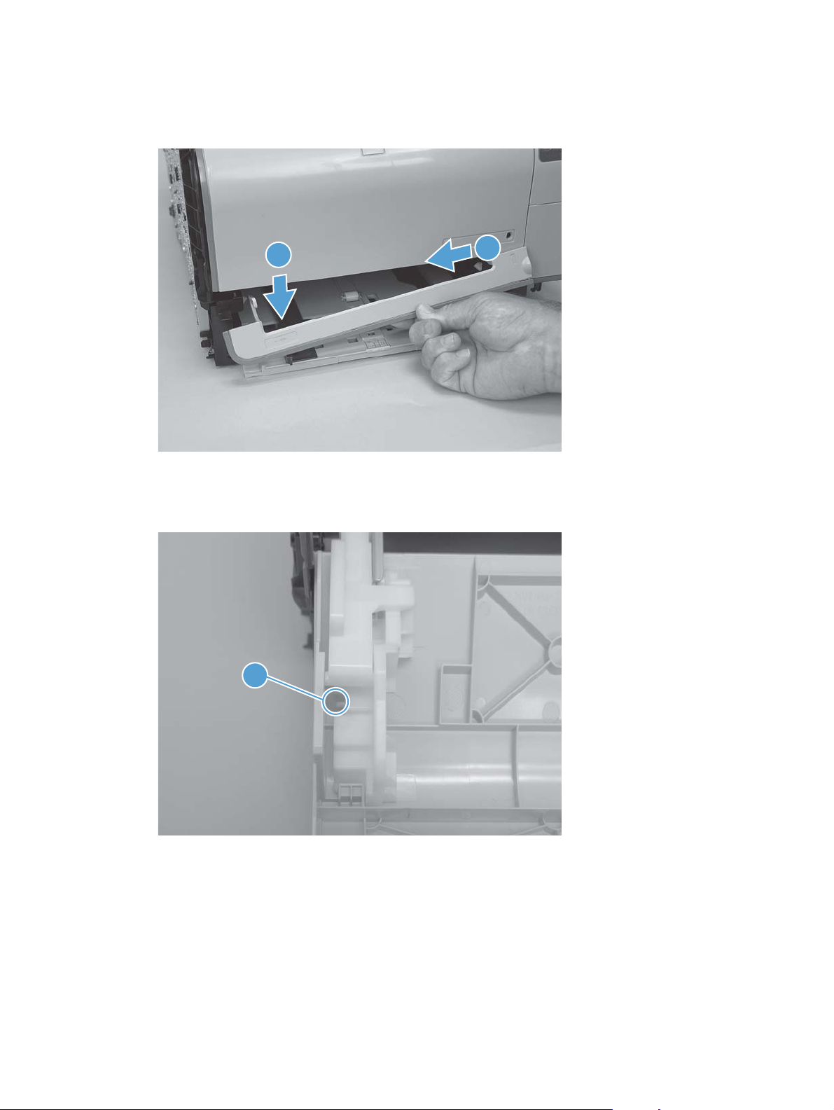
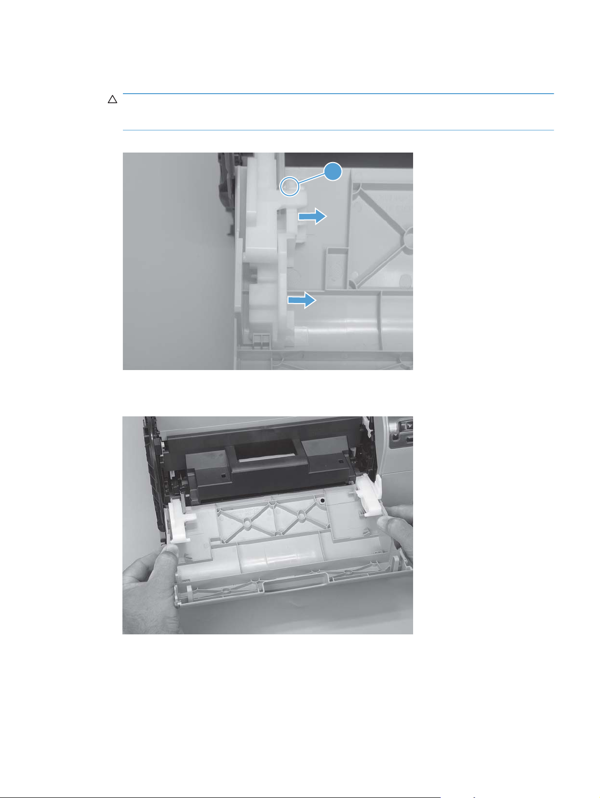
2. Release one captive screw (callout 1) and release two tabs (callout 2).
Figure 1-10 Remove the feed assembly (1 of 2)
2
1
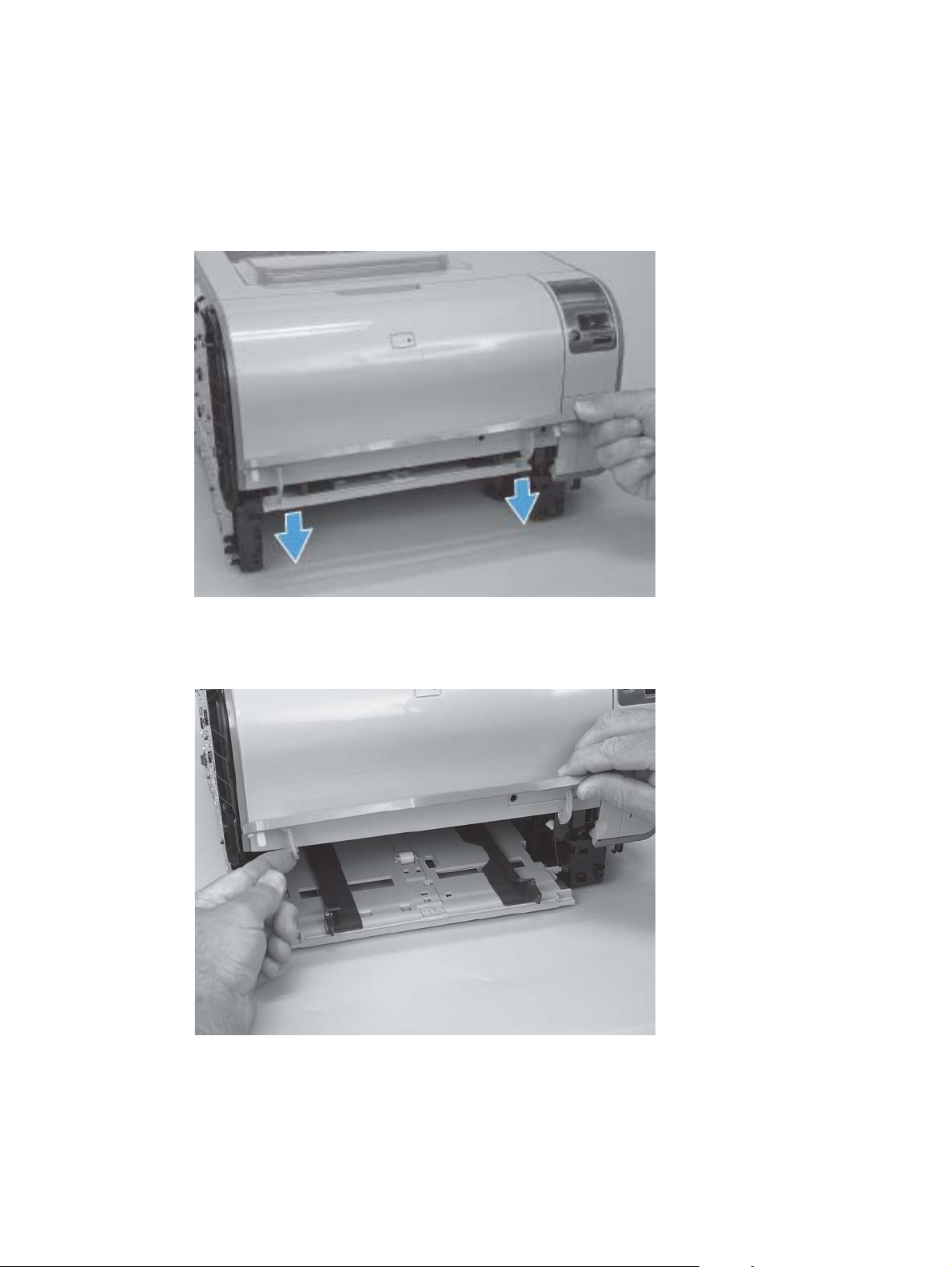
3. Remove the transfer roller assembly
Figure 1-11 Remove the feed assembly (2 of 2)
External panels, covers, and doors
Right cover
1. Remove Tray 2.
10 Chapter 1 Removal and replacement ENWW
Page 24
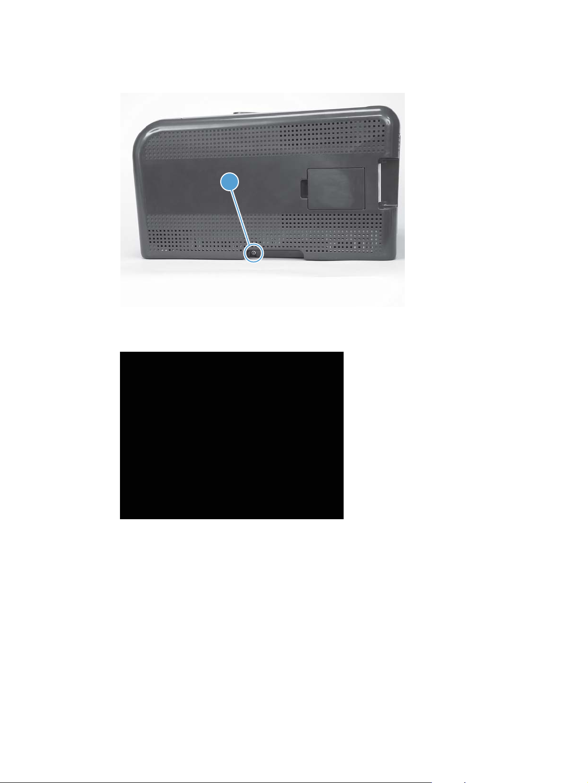
2. Remove one screw (callout 1).
Figure 1-12 Remove the right cover (1 of 4)
1
3. Carefully pry the front of the right cover away from the product to release one tab.
Figure 1-13 Remove the right cover (2 of 4)
ENWW Removal and replacement procedures 11
Page 25
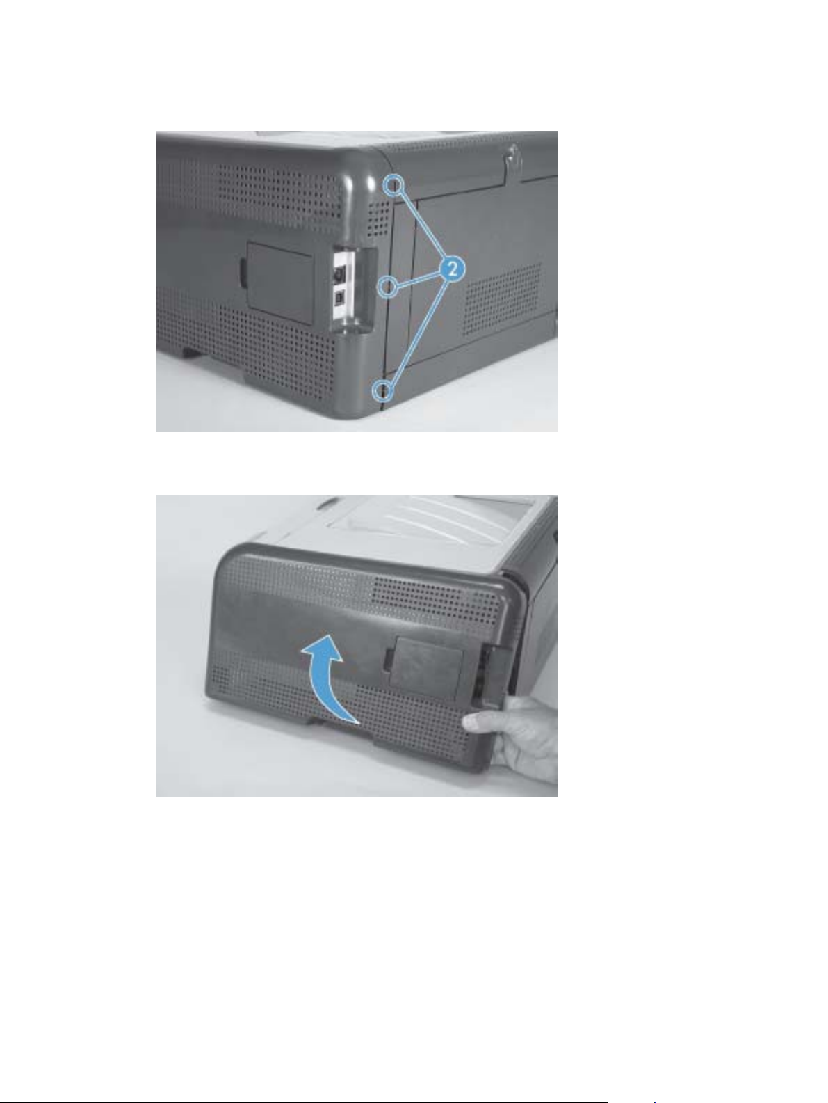
4. Use a small flatblade screwdriver to release three tabs (callout 2) at the back of the product.
Figure 1-14 Remove the right cover (3 of 4)
5. Rotate the bottom of the cover away from the product, and then slide it up to remove it.
Figure 1-15 Remove the right cover (4 of 4)
12 Chapter 1 Removal and replacement ENWW
Page 26
Left cover
1. Remove Tray 2.
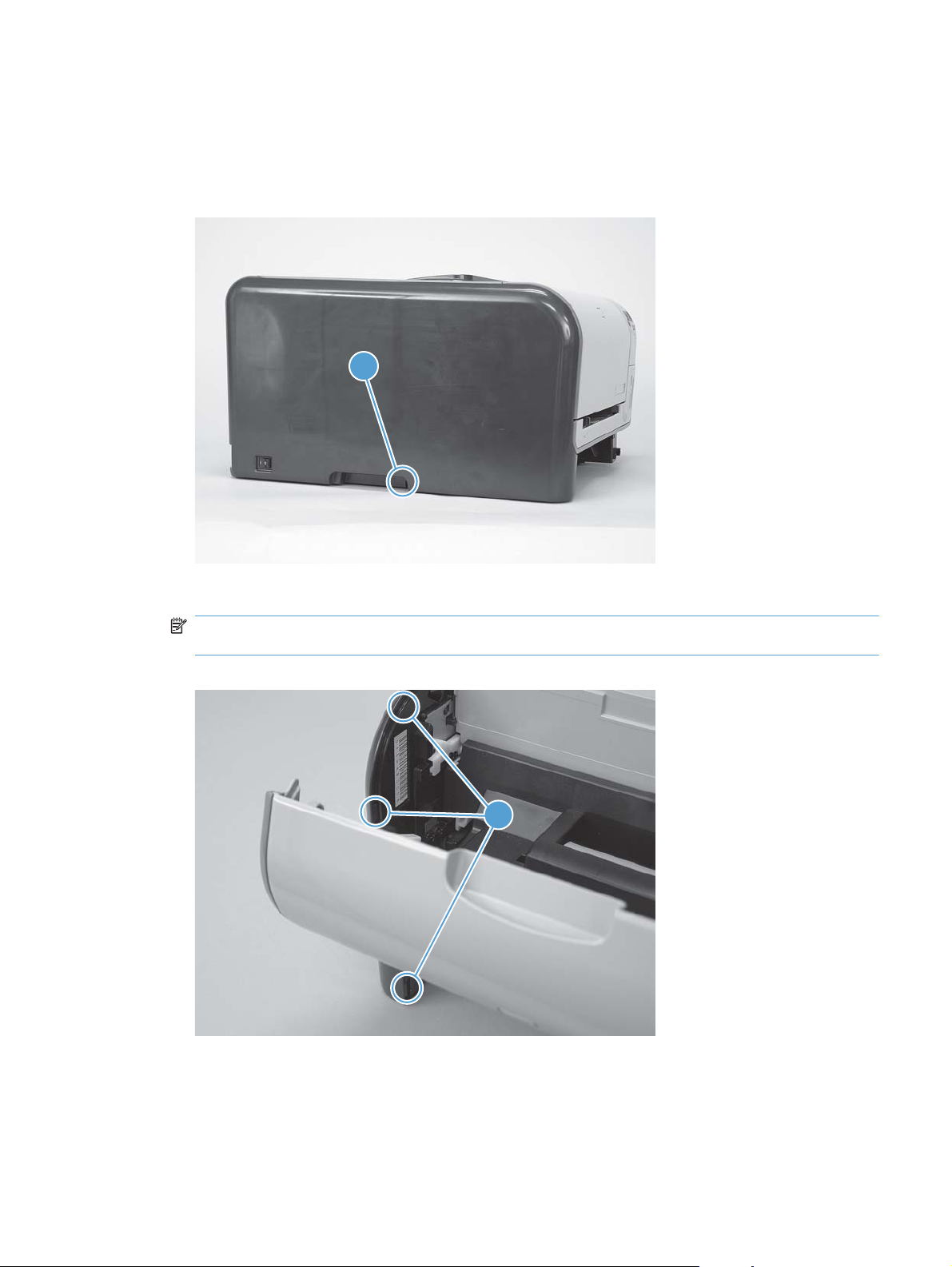
2. Remove one screw (callout 1).
Figure 1-16 Remove the left cover (1 of 4)
1
3. Open the front door, and then use a small flatblade screwdriver to release three tabs (callout 2).
NOTE: It might be easier to release the tabs if you first release the bottom tab, then the middle
tab, and then the top tab.
Figure 1-17 Remove the left cover (2 of 4)
2
ENWW Removal and replacement procedures 13
Page 27
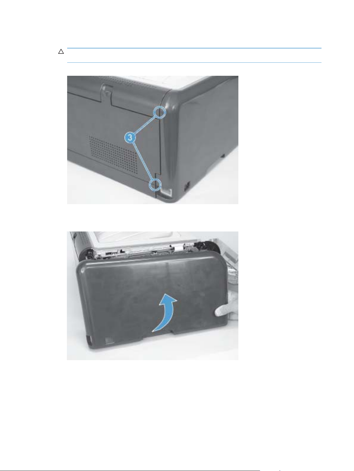
4. Use a small flatblade screwdriver to release two tabs (callout 3) at the back of the product.
CAUTION: The bottom tab might be difficult to release. Make sure that you do not break the
tab.
Figure 1-18 Remove the left cover (3 of 4)
5. Rotate the bottom of the cover away from the product, and then slide it up to remove it.
Figure 1-19 Remove the left cover (4 of 4)
14 Chapter 1 Removal and replacement ENWW
Page 28
Front door and Tray 1 door
The Tray 1 door is located below the front door.
1. Open the Tray 1 door.
Push down on the priority-feed tray to release it.
Figure 1-20 Remove the front door and Tray 1 door (1 of 7)
2. Carefully push the left-side Tray 1 door hinge in toward the center of the door to release it from
the hinge pin.
Figure 1-21 Remove the front door and Tray 1 door (2 of 7)
ENWW Removal and replacement procedures 15
Page 29
3. Lower the left side of the door and then slide it to the left to release the right-side hinge. Remove
the door.
Figure 1-22 Remove the front door and Tray 1 door (3 of 7)
1
4. Open the front door, and then use a small flatblade screwdriver to release one tab (callout 1) on
the left-side front-door cam.
Figure 1-23 Remove the front door and Tray 1 door (4 of 7)
2
1
16 Chapter 1 Removal and replacement ENWW
Page 30
5. Slide the cam toward the center of the door to remove it. Repeat this step for the right-side front-
door cam.
CAUTION: The hinge pin (callout 2) on the cam can be easily broken. You must apply even
pressure on the cam to remove it without using any twisting motion that might break the hinge
pin off of the cam.
Figure 1-24 Remove the front door and Tray 1 door (5 of 7)
2
6. Carefully flex the edges of the door to release the right- and left-side door retainer arms.
Figure 1-25 Remove the front door and Tray 1 door (6 of 7)
ENWW Removal and replacement procedures 17
Page 31

7. Lower the left side of the door, and then slide it to the left to release the right-side door hinge pin.
Remove the door.
Figure 1-26 Remove the front door and Tray 1 door (7 of 7)
1
2
18 Chapter 1 Removal and replacement ENWW
Page 32

Control-panel module
CAUTION: Do not bend or fold the flat flexible cables (FFCs) during removal or installation. Also, do
not straighten pre-folds in the FFCs. You must make sure that all FFCs are fully seated in their
connectors. Failure to fully seat an FFC into a connector can cause a short circuit in a PCA.
1. Remove the right cover. See Right cover on page 10.
2. Open the front door.
3. Disconnect one FFC (callout 1), one wire-harness connector (callout 2), and then remove one
screw (callout 3).
Figure 1-27 Remove the control-panel module (1 of 3)
1
3
2
TIP: The control-panel mounting screw (callout 3) is a self-tapping screw. When reinstalling the
control-panel module, make sure that you replace this screw in the correct position in the
product.
4. Use a small flatblade screwdriver to release one tab (callout 4).
Figure 1-28 Remove the control-panel module (2 of 3)
4
ENWW Removal and replacement procedures 19
Page 33

5. Rotate the top of the control-panel module away from the product to remove it.
Figure 1-29 Remove the control-panel module (3 of 3)
20 Chapter 1 Removal and replacement ENWW
Page 34

Rear-side cover
1. Remove the right cover. See Right cover on page 10.
2. Open the rear door.
3. Use a small flatblade screwdriver to release two tabs (callout 1).
Figure 1-30 Remove the rear-side cover (1 of 2)
1
4. Remove the rear-side cover.
TIP: Note the location of the mounting tabs (callout 2) on the rear-side cover.
Figure 1-31 Remove the rear-side cover (2 of 2)
2
2
ENWW Removal and replacement procedures 21
Page 35

Rear-upper cover
1. Remove the following components:
Right cover. See
●
Left cover. See
●
Rear-side cover. See
●
2. Open the rear door.
3. Use a small flatblade screwdriver to release two tabs (callout 1).
Figure 1-32 Remove the rear-upper cover (1 of 2)
Right cover on page 10.
Left cover on page 13.
Rear-side cover on page 21.
1
4. Pull the rear-upper cover away from the product to remove it.
Figure 1-33 Remove the rear-upper cover (2 of 2)
22 Chapter 1 Removal and replacement ENWW
Page 36

Rear door and rear-lower cover
1. Remove the following components:
Right cover. See
●
Left cover. See
●
Rear-side cover. See
●
2. Remove two screws (callout 1).
Figure 1-34 Remove the rear door and rear-lower cover (1 of 4)
Right cover on page 10.
Left cover on page 13.
Rear-side cover on page 21.
1
3. Release one pin (callout 2), and then slide the rear door and rear-lower cover toward the side of
the product with the interface connectors.
Figure 1-35 Remove the rear door and rear-lower cover (2 of 4)
2
ENWW Removal and replacement procedures 23
Page 37

4. Remove the rear door and rear-lower cover.
Figure 1-36 Remove the rear door and rear-lower cover (3 of 4)
5. Rotate the rear-door hinge arms and slide it off of the hinge pins on the rear-lower cover to
separate the rear cover from the rear door.
NOTE: If you are installing a replacement rear-lower door, remove the feed assembly from the
discarded door, and then install it on the replacement door. See
Figure 1-37 Remove the rear door and rear-lower cover (4 of 4)
Feed assembly on page 9.
24 Chapter 1 Removal and replacement ENWW
Page 38

Top cover
1. Remove the following components:
Right cover. See
●
Left cover. See
●
Control-panel module. See
●
Rear-side cover. See
●
Rear-upper cover. See
●
2. Partially open the front door.
3. Remove one screw (callout 1).
Figure 1-38 Remove the top cover (1 of 4)
Right cover on page 10.
Left cover on page 13.
Rear-side cover on page 21.
Rear-upper cover on page 22.
Control-panel module on page 19.
ENWW Removal and replacement procedures 25
Page 39

4. Release one tab (callout 2).
Figure 1-39 Remove the top cover (2 of 4)
5. Release two tabs (callout 3).
Figure 1-40 Remove the top cover (3 of 4)
2
3
26 Chapter 1 Removal and replacement ENWW
Page 40

6. Remove the top cover.
Figure 1-41 Remove the top cover (4 of 4)
Internal assemblies
Main motor
1. Remove the right cover. See Right cover on page 10.
2. Disconnect one wire-harness connector (callout 1), and then release two tabs (callout 2) to
release the retainer (callout 3). Slide the retainer down and separate it from the chassis.
Figure 1-42 Remove the main motor (1 of 2)
3
1
2
ENWW Removal and replacement procedures 27
Page 41

3. Remove four screws (callout 4), and then remove the main motor.
Figure 1-43 Remove the main motor (2 of 2)
4
28 Chapter 1 Removal and replacement ENWW
Page 42

Fuser motor
1. Remove the right cover. See Right cover on page 10.
2. Disconnect one wire-harness connector (callout 1).
Figure 1-44 Remove the fuser motor (1 of 2)
1
3. Remove two screws (callout 2), and then remove the fuser motor.
Figure 1-45 Remove the fuser motor (2 of 2)
2
ENWW Removal and replacement procedures 29
Page 43

Intermediate transfer belt (ITB)
1. Remove the following components:
Right cover. See
●
Left cover. See
●
Rear-side cover. See
●
2. Open the front door and pull out the print-cartridge drawer.
Figure 1-46 Remove the ITB (1 of 9)
3. Release one tab (callout 1).
Right cover on page 10.
Left cover on page 13.
Rear-side cover on page 21.
Figure 1-47 Remove the ITB (2 of 9)
1
30 Chapter 1 Removal and replacement ENWW
Page 44

4. Rotate the cartridge-drawer retainer (callout 1) away from the chassis, and then remove it
(callout 2). Repeat the previous step and this step for the left–side cartridge-drawer retainer.
Figure 1-48 Remove the ITB (3 of 9)
1
2
5. Pull the print-cartridge drawer straight out of the product to remove it.
Figure 1-49 Remove the ITB (4 of 9)
ENWW Removal and replacement procedures 31
Page 45

6. Disconnect one wire-harness connector (callout 3), and then release the wire harness from the
retainer (callout 4).
Figure 1-50 Remove the ITB (5 of 9)
3
4
7. Open the rear door.
8. Remove one screw (callout 5), and then remove the print-cartridge drawer stop (callout 6).
Figure 1-51 Remove the ITB (6 of 9)
5
6
32 Chapter 1 Removal and replacement ENWW
Page 46

9. Carefully lift up on the black plastic portion of the ITB, and then pull it partially out of the product
(the ITB wire harness will prevent the ITB from being fully removed).
WARNING! Only partially pull the ITB out of the product to avoid damage to the secondary-
transfer (T2) roller.
CAUTION: Avoid touching the black plastic transfer belt. Skin oils on the belt might cause
print-quality problems.
Figure 1-52 Remove the ITB (7 of 9)
10. Feed the ITB wire harness (callout 7) through an opening in the chassis (callout 8).
Figure 1-53 Remove the ITB (8 of 9)
7
8
ENWW Removal and replacement procedures 33
Page 47

11. Carefully pull the ITB straight out of the product.
WARNING! Handle the ITB by its hard plastic sides to avoid damage to the sheet-metal frame.
The lower sheet-metal portion of the ITB frame can be easily bent. See
ITB (1 of 2) on page 35.
CAUTION: Make sure that the ITB wire harness does not get damaged as the ITB is removed
from the chassis.
Figure 1-54 Remove the ITB (9 of 9)
Figure 1-55 Reinstall the
34 Chapter 1 Removal and replacement ENWW
Page 48

Reinstall the ITB
Use the following guidelines when you install the ITB.
●
WARNING! The lower sheet-metal portion of the ITB frame (callout 1) can be easily bent.
Avoid handling the ITB by this part of the sheet-metal frame.
Figure 1-55 Reinstall the ITB (1 of 2)
1
● When handling the ITB, always hold it using the hard plastic portions of the assembly.
CAUTION: Avoid touching the black-plastic transfer belt or roller. Skin oils on the belt or roller
might cause print-quality problems.
Do not let the transfer belt contact hard or sharp objects.
●
CAUTION: Scratches, punctures, or other damage to the belt will cause print-quality problems.
Make sure that the wire harness is not twisted or pinched after it is passed through the opening
●
in the chassis and that the ITB sits flat in the product.
NOTE: When the print-cartridge drawer is installed, it should easily slide in and out of the
product and not contact any part of the ITB assembly.
ENWW Removal and replacement procedures 35
Page 49

Tape the wire harness to the sheet-metal frame so that it will not catch on internal components
●
as the ITB is installed.
With the ITB partially installed, feed the wire harness through the opening in the chassis. See
Figure 1-53 Remove the ITB (8 of 9) on page 33. Finish installing the ITB.
WARNING! Do not place the tape so that it makes contact with or adheres to the transfer belt.
Tape or tape residue on the transfer belt will cause print-quality problems.
NOTE: Make sure that you remove all of the tape and tape residue after installing the ITB.
Figure 1-56 Reinstall the ITB (2 of 2)
36 Chapter 1 Removal and replacement ENWW
Page 50

DC controller PCA
Special consideration
WARNING! Do not install a replacement formatter PCA and DC controller PCA at the same time,
and then turn the product power on.
The formatter PCA and the DC controller PCA store important product configuration information
(NVRAM data) that will be lost if both PCAs are replaced at the same time. When the product power
is turned on, the formatter will restore the NVRAM data to a replacement DC controller.
Replacing both the DC controller and the formatter at the same time will result in severe print-quality
problems.
Replacing the DC controller PCA before the formatter PCA
Use the following procedure if you need to install a replacement DC controller and a replacement
formatter PCA.
NOTE: If you are only installing a replacement DC controller PCA, proceed to DC controller PCA
on page 37.
1. Install a replacement DC controller PCA.
2. Turn the product power on, and wait for the print-cartridge volume indicators to appear on the
control-panel display.
NOTE: This allows important product information to be written to the replacement DC controller
PCA.
3. Turn the product power off.
4. Install a replacement formatter PCA. See
5. Turn the product power on.
Remove the DC controller PCA
CAUTION: Do not bend or fold the flat flexible cables (FFCs) during removal or installation. Also, do
not straighten pre-folds in the FFCs. You must make sure that all FFCs are fully seated in their
connectors. Failure to fully seat an FFC into a connector can cause a short circuit in a PCA.
Some parts are sensitive to electrostatic discharge (ESD). Look for the ESD reminder when
removing product parts. Always perform service work at an ESD-protected workstation or mat. If an
ESD workstation or mat is not available, ground yourself by touching the sheet-metal chassis before
touching an ESD-sensitive part.
1. Remove the following components:
Right cover. See
●
Left cover. See
●
Formatter PCA on page 40.
Right cover on page 10.
Left cover on page 13.
Control-panel module. See
●
● Rear-side cover. See
ENWW Removal and replacement procedures 37
Control-panel module on page 19.
Rear-side cover on page 21.
Page 51

Rear-upper cover. See
●
Rear-upper cover on page 22.
Top cover. See
●
2. Release two tabs (callout 1), and then remove the protective cover (callout 2).
Figure 1-57 Remove the DC controller PCA (1 of 3)
Top cover on page 25.
1
2
3. Disconnect all of the FFCs and wire-harness connectors from the DC controller PCA.
Three FFCs: J107, J108, and J115
●
Wire harness
●
15 wire-harness connectors: J012, J104, J105, J109, J110, J111, J112, J113, J116,
◦
J117, J118, J119, J120, J121, and J124
NOTE: J126 and J127 are not used.
Figure 1-58 Remove the DC controller PCA (2 of 3)
38 Chapter 1 Removal and replacement ENWW
Page 52

4. Remove four screws (callout 3), and then remove the DC controller PCA.
NOTE: These four screws are ground screws. Make sure that the correct screws are used to
reinstall the DC controller PCA.
Figure 1-59 Remove the DC controller PCA (3 of 3)
3
ENWW Removal and replacement procedures 39
Page 53

Formatter PCA
Special consideration
WARNING! Do not install a replacement formatter PCA and DC controller PCA at the same time,
and then turn the product power on.
The formatter PCA and the DC controller PCA store important product configuration information
(NVRAM data) that will be lost if both PCAs are replaced at the same time. When the product power
is turned on, the DC controller will restore the NVRAM data on the replacement formatter.
Replacing both the formatter and the DC controller at the same time will result in severe print-quality
problems.
Replacing the formatter PCA before the DC controller PCA
Use the following procedure if you need to install a replacement formatter PCA and a replacement
DC controller.
NOTE: If you are only installing a replacement formatter PCA, proceed to Remove the formatter
PCA on page 40.
1. Install a replacement formatter PCA.
2. Turn the product power on, and wait for the print-cartridge volume indicators to appear on the
control-panel display.
NOTE: This allows important product information to be written to the replacement formatter
PCA.
3. Turn the product power off.
4. Install a replacement DC controller. See
5. Turn the product power on.
Remove the formatter PCA
CAUTION: Do not bend or fold the flat flexible cables (FFCs) during removal or installation. Also, do
not straighten pre-folds in the FFCs. You must make sure that all FFCs are fully seated in their
connectors. Failure to fully seat an FFC into a connector can cause a short circuit in a PCA.
Some parts are sensitive to electrostatic discharge (ESD). Look for the ESD reminder when
removing product parts. Always perform service work at an ESD-protected workstation or mat. If an
ESD workstation or mat is not available, ground yourself by touching the sheet-metal chassis before
touching an ESD-sensitive part.
1. Remove the right cover. See Right cover on page 10.
DC controller PCA on page 37.
40 Chapter 1 Removal and replacement ENWW
Page 54

2. Disconnect all of the FFCs and wire-harness connectors from the formatter PCA.
FFCs
●
J2 and J5
◦
Wire-harness connectors
●
J1 and P4
◦
Figure 1-60 Remove the formatter PCA (1 of 2)
3. Remove four screws (callout 1), and then remove the formatter PCA.
Figure 1-61 Remove the formatter PCA (2 of 2)
1
ENWW Removal and replacement procedures 41
Page 55

Wireless PCA
1. Remove the following components:
Right cover. See
●
2. Remove one screw (callout 1)
3. Release one tab (callout 2)
4. Disconnect one wire-harness connector (callout 3)
Figure 1-62 Remove the wireless PCA
Right cover on page 10.
2
3
1
42 Chapter 1 Removal and replacement ENWW
Page 56

Power supply (high-voltage)
CAUTION: Do not bend or fold the flat flexible cables (FFCs) during removal or installation. Also, do
not straighten pre-folds in the FFCs. You must make sure that all FFCs are fully seated in their
connectors. Failure to fully seat an FFC into a connector can cause a short circuit in a PCA.
1. Remove the following components:
Right cover. See
●
Left cover. See
●
Control-panel module. See
●
● Rear-side cover. See
Rear-upper cover. See
●
Top cover. See
●
2. Disconnect one FFC (callout 1; J107) on the DC controller.
Figure 1-63 Remove the power supply (high-voltage; 1 of 6)
Right cover on page 10.
Left cover on page 13.
Control-panel module on page 19.
Rear-side cover on page 21.
Rear-upper cover on page 22.
Top cover on page 25.
1
ENWW Removal and replacement procedures 43
Page 57

3. Disconnect two wire-harness connectors (callout 2) and release the wire harness from the
retainer (callout 3).
Figure 1-64 Remove the power supply (high-voltage; 2 of 6)
2
3
4. Remove one screw (callout 4), and then release the sub-PCA from the chassis (callout 5).
Figure 1-65 Remove the power supply (high-voltage; 3 of 6)
5
4
44 Chapter 1 Removal and replacement ENWW
Page 58

5. Remove four screws (callout 6).
NOTE: The screw at the lower back of the power supply is a ground screw. Make sure that this
screw is placed in the correct position when the power supply is reinstalled.
Figure 1-66 Remove the power supply (high-voltage; 4 of 6)
6
6. Release seven tabs (callout 7).
Figure 1-67 Remove the power supply (high-voltage; 5 of 6)
7
7
ENWW Removal and replacement procedures 45
Page 59

7. Remove the power supply.
Figure 1-68 Remove the power supply (high-voltage; 6 of 6)
Reinstall the power supply (high voltage)
Make sure that the power supply is correctly positioned under the tabs (callout 1) located on the
●
product chassis. If the power supply is not correctly installed, the product will not function
correctly and a fuser open error (50.7000) might appear in the event log.
Figure 1-69 Reinstall the power supply (high voltage)
1
46 Chapter 1 Removal and replacement ENWW
Page 60

Power supply (low-voltage)
CAUTION: Do not bend or fold the flat flexible cables (FFCs) during removal or installation. Also, do
not straighten pre-folds in the FFCs. You must make sure that all FFCs are fully seated in their
connectors. Failure to fully seat an FFC into a connector can cause a short circuit in a PCA.
1. Remove the following components:
Right cover. See
●
Left cover. See
●
Rear-side cover. See
●
● Rear door and rear-lower cover. See
2. Remove two screws (callout 1) and the power-supply cover (callout 2).
Figure 1-70 Remove the power supply (low-voltage; 1 of 10)
Right cover on page 10.
Left cover on page 13.
Rear-side cover on page 21.
Rear door and rear-lower cover on page 23.
2
1
ENWW Removal and replacement procedures 47
Page 61

3. Disconnect one wire-harness connector (callout 3) and release the wire harness from the
retainer (callout 4).
TIP: It might be easier to release one tab, and then remove the retainer from the product
chassis.
Figure 1-71 Remove the power supply (low-voltage; 2 of 10)
3
4
4. Release two tabs (callout 5), and then remove the protective cover (callout 6).
Figure 1-72 Remove the power supply (low-voltage; 3 of 10)
5
6
48 Chapter 1 Removal and replacement ENWW
Page 62

5. Disconnect two wire-harness connectors (callout 7; J102 and J103).
Figure 1-73 Remove the power supply (low-voltage; 4 of 10)
7
6. Disconnect one connector (callout 8; P4), and then remove four screws (callout 9) to release the
formatter PCA from the chassis.
NOTE: You do not need to remove the PCA. Instead, release it from the chassis so it can be
moved out of the way.
TIP: When you reinstall the formatter PCA, make sure that all of the connectors on the PCA
are fully seated.
Figure 1-74 Remove the power supply (low-voltage; 5 of 10)
9
8
ENWW Removal and replacement procedures 49
Page 63

7. Release the wire harness (callout 10) from the retainer.
Figure 1-75 Remove the power supply (low-voltage; 6 of 10)
10
8. Release two tabs (callout 11), and then carefully remove the retainer (callout 12).
NOTE: It might be easier to remove this retainer if you first move the cable that connects the
formatter PCA out of the way, and hold the formatter PCA out and away from the chassis.
Figure 1-76 Remove the power supply (low-voltage; 7 of 10)
11
12
50 Chapter 1 Removal and replacement ENWW
Page 64

9. Remove two screws (callout 13).
Figure 1-77 Remove the power supply (low-voltage; 8 of 10)
13
10. Pull the power supply away from the chassis (it will not come completely out).
Figure 1-78 Remove the power supply (low-voltage; 9 of 10)
ENWW Removal and replacement procedures 51
Page 65

11. Rotate the end of the power supply near the control-panel module out and away from the
product until it clears the chassis, and then slide the power supply toward the control-panel
module to remove it.
NOTE: As you remove the power supply, feed the wire harness at the rear of the product
through the opening in the chassis.
TIP: Make sure that the tab on the right end of the power-supply chassis fits into the slot on the
product chassis, and the left-hand side of the tray rides on top of the ledge of the chassis, when
the power supply is reinstalled.
Figure 1-79 Remove the power supply (low-voltage; 10 of 10)
2
1
52 Chapter 1 Removal and replacement ENWW
Page 66

Power supply (fuser)
1. Remove the following components:
Right cover. See
●
Left cover. See
●
Rear-side cover. See
●
Rear door and rear-lower cover. See
●
2. Remove two screws (callout 1) and the power-supply cover (callout 2).
Figure 1-80 Remove the power supply (fuser; 1 of 5)
Right cover on page 10.
Left cover on page 13.
Rear-side cover on page 21.
Rear door and rear-lower cover on page 23.
2
1
3. Disconnect three wire-harness connectors (callout 3).
Figure 1-81 Remove the power supply (fuser; 2 of 5)
3
ENWW Removal and replacement procedures 53
Page 67

4. Release one tab (callout 4), slide the retainer toward the interface connectors to release it, and
then separate the retainer from the chassis.
Figure 1-82 Remove the power supply (fuser; 3 of 5)
4
5. Remove four screws (callout 5).
NOTE: The two screws near the power switch are ground screws. Make sure that these
screws are placed in the correct positions when the power supply is reinstalled.
Figure 1-83 Remove the power supply (fuser; 4 of 5)
5
5
54 Chapter 1 Removal and replacement ENWW
Page 68

6. Remove the power supply.
Figure 1-84 Remove the power supply (fuser; 5 of 5)
ENWW Removal and replacement procedures 55
Page 69

Fuser
1. Remove the following components:
Right cover. See
●
Left cover. See
●
Control-panel module. See
●
Rear-side cover. See
●
Rear-upper cover. See
●
Rear door and rear-lower cover. See
●
Top cover. See
●
2. Remove two screws (callout 1) and the power-supply cover (callout 2).
Figure 1-85 Remove the fuser (1 of 4)
Right cover on page 10.
Left cover on page 13.
Control-panel module on page 19.
Rear-side cover on page 21.
Rear-upper cover on page 22.
Rear door and rear-lower cover on page 23.
Top cover on page 25.
2
1
56 Chapter 1 Removal and replacement ENWW
Page 70

3. Disconnect five wire-harness connectors (callout 3). Remove the wire harness from the guides
and one retainer.
Figure 1-86 Remove the fuser (2 of 4)
3
3
4. Remove four screws (callout 4).
Figure 1-87 Remove the fuser (3 of 4)
4
ENWW Removal and replacement procedures 57
Page 71

5. Remove the fuser.
CAUTION: Handle the fuser carefully. The sensors that are mounted to the output side of the
fuser can be easily dislodged. When the fuser is reinstalled, make sure that the sensors are
present, and correctly fastened to the fuser assembly.
Figure 1-88 Remove the fuser (4 of 4)
58 Chapter 1 Removal and replacement ENWW
Page 72

2 Solve problems
Solve problems checklist
●
Menu map
●
Troubleshooting process
●
Tools for troubleshooting
●
Paper feeds incorrectly or becomes jammed
●
Solve image quality problems
●
Clean the product
●
The product does not print or it prints slowly
●
Solve connectivity problems
●
Service mode functions
●
Product updates
●
ENWW 59
Page 73

Solve problems checklist
1. Make sure that the product is set up correctly.
a. Press the power button to turn on the product or to deactivate the Auto-Off mode.
b. Check the power-cable connections.
c. Make sure that the line voltage is correct for the product power configuration. (See the label
that is on the back of the product for voltage requirements.) If you are using a power strip
and its voltage is not within specifications, plug the product directly into the wall. If it is
already plugged into the wall, try a different outlet.
2. Check the cabling.
a. Check the cable connection between the product and the computer. Make sure that the
connection is secure.
b. Make sure that the cable itself is not faulty by using a different cable, if possible.
c. Check the network connection (HP Color LaserJet CP1525nw only): Make sure the network
light is lit. The network light is next to the network port on the back of the product.
If the product remains unable to connect to the network, uninstall and then reinstall the
product. If the error persists, contact a network administrator.
3. Check to see if any messages appear on the control panel.
4. Make sure that the paper that you are using meets specifications.
5. Make sure that the paper is loaded correctly in the input tray.
6. Make sure that the product software is installed correctly.
7. Verify that you have installed the printer driver for this product, and that you are selecting this
product from the list of available printers.
8. Print a configuration page.
a. If the page does not print, verify that the input tray contains paper and that the paper is
properly loaded.
b. Make sure that the print cartridge is installed correctly.
c. If the page jams in the product, clear the jam.
d. If the print quality is unacceptable, complete the following steps:
Verify that the print settings are correct for the paper that you are using.
●
Solve print-quality problems.
●
9. Print a small document from a different program that has worked in the past. If this solution
works, then the problem is with the program you are using. If this solution does not work (the
document does not print), complete these steps:
a. Try printing the job from another computer that has the product software installed.
b. Check the cable connection. Direct the product to the correct port, or reinstall the software,
selecting the connection type that you are using.
60 Chapter 2 Solve problems ENWW
Page 74

Menu map
Use the Reports menu to print a menu map of the control panel-menu layout. The active settings for
each menu are listed.
1. Press OK to open the menus.
2. Press the left arrow
button.
3. Press the left arrow
OK button to print the report.
4. Press X to exit the menus.
or right arrow button to navigate to Reports, and then press the OK
or right arrow button to navigate to Menu structure, and then press the
ENWW Menu map 61
Page 75

Troubleshooting process
When the product malfunctions or encounters an unexpected situation, the product control panel
alerts you to the situation. This chapter contains information to help diagnose and solve problems.
Use the pre-troubleshooting checklist to evaluate the source of the problem and to reduce the
●
number of steps that are required to fix the problem.
Use the troubleshooting flowchart to pinpoint the root cause of hardware malfunctions. The
●
flowchart guides you to the section of this chapter that contains steps for correcting the
malfunction.
Before beginning any troubleshooting procedure, check the following issues:
Are supply items within their rated life?
●
Does the configuration page reveal any configuration errors?
●
NOTE: The customer is responsible for checking supplies and for using supplies that are in good
condition.
Pre-troubleshooting checklist
The following table includes basic questions to ask the customer to quickly help define the
problem(s).
General topic Questions
Environment ● Is the product installed on a solid, level surface (+/- 1°)?
Is the power-supply voltage within ± 10 volts of the specified power source?
●
Is the power-supply plug inserted in the product and the outlet?
●
● Is the operating environment within the specified parameters?
● Is the product exposed to ammonia gas, such as that produced by diazo
copiers or office cleaning materials?
NOTE: Diazo copiers produce ammonia gas as part of the copying
processes. Ammonia gas (from cleaning supplies or a diazo copier) can have
an adverse affect on some product components (for example, the printcartridge OPC).
Is the product exposed to direct sunlight?
●
Media ● Does the customer use only supported media?
Is the media in good condition (no curls, folds, or distortion)?
●
Is the media stored correctly and within environmental limits?
●
Input trays ● Is the amount of media in the tray within specifications?
Is the media correctly placed in the tray?
●
Are the paper guides aligned with the stack?
●
● Is the cassette correctly installed in the product?
Print cartridges ● Is each print cartridge installed correctly?
Transfer unit and fuser
Are the transfer unit and fuser installed correctly?
●
62 Chapter 2 Solve problems ENWW
Page 76

General topic Questions
Covers ● Is the front cover closed?
Condensation
Miscellaneous ● Check for and remove any non-HP components (print cartridges, memory
Does condensation occur following a temperature change (particularly in
●
winter following cold storage)? If so, wipe affected parts dry or leave the
product on for 10 to 20 minutes.
Was a print cartridge opened soon after being moved from a cold to a warm
●
room? If so, allow the print cartridge to sit at room temperature for 1 to 2
hours.
modules, and EIO cards) from the product.
If the hardware or software configuration has not changed or the problem is
●
not associated with any specific software, see the complete service manual
for this product.
Remove the product from the network and ensure that the failure is
●
associated with the product before beginning troubleshooting.
● For any print-quality issues, calibrate the product.
ENWW Troubleshooting process 63
Page 77

Power-on checks
When you turn on the product, if it does not make any sound or if the control-panel display is blank,
check the following items:
Verify that the product is plugged directly into an active electrical outlet that has the correct
●
voltage. Do not plug the product into a surge protector or power strip.
Verify that the on/off switch is in the on position.
●
Verify that the formatter is seated and operating correctly.
●
● Remove any HP Jetdirect accessories or other devices, and then try to turn the product on
again.
Make sure that the control-panel display is connected.
●
● Check the two fuses on the power supply.
● If necessary, replace the power supply.
If necessary, replace the DC controller.
●
64 Chapter 2 Solve problems ENWW
Page 78

Tools for troubleshooting
Diagrams
Plug/jack locations
1 Network port
1
2
2 Hi-Speed USB 2.0 port
ENWW Tools for troubleshooting 65
Page 79

Locations of major components
Figure 2-1 Major components
2
1
3
4
6
Table 2-1 Major components
Item Description
1 Fuser power supply
2 Fuser assembly
5
66 Chapter 2 Solve problems ENWW
Page 80

Table 2-1 Major components (continued)
Item Description
3 Sub-drive assembly
4 Low-voltage power suppy
5 Main drive assembly
6ITB assembly
ENWW Tools for troubleshooting 67
Page 81

General timing charts
The following charts lists the approximate timing for this product, specified in seconds.
Figure 2-2 Timing diagram
STBY
LSTR
PRNT
INTR
Print command
STBY
Operation
3.9
3.5
Fuser temperature control
Main motor (M701)
Pickup motor (M702)
1
2
Fuser motor (M703)
3
4
6.1
4.4
2.0
Scanner motor (M704)
Cassette pickup
solenoid (SL705)
Developing disengagement
6
solenoid (SL706)
7
5
21.2
7.6
6.1
1.6
Top of page sensor (SR602)
Fixing delivery sensor (SR609)
8
TOP OF PAGE signal (/TOP)
9
10
4.7
4.4
4.4
Primary charging bias
11
Developing bias (Y, M, C)
Developing bias (Bk)
12
13
2.1
7.417.3
10.5
6.1
0.5
Primary transfer bias (Y)
Primary transfer bias (M, C)
Primary transfer bias (Bk)
14
15
Secondary transfer bias
16
17
Print biasATVC Between-sheets bias
18
19
20
68 Chapter 2 Solve problems ENWW
Page 82

General circuit diagram
Figure 2-3 Circuit diagram
ENWW Tools for troubleshooting 69
Page 83

Use HP ToolboxFX
The HP Color LaserJet CP1520 Series Toolbox is a program you can use to complete the following
tasks:
Check the product status.
●
● Configure the product settings.
● View troubleshooting information.
You can view the HP Color LaserJet CP1520 Series Toolbox program when the product is directly
connected to your computer or is connected to the network. You must perform a recommended
software installation to use the HP Color LaserJet CP1520 Series Toolbox program.
NOTE: The HP Color LaserJet CP1520 Series Toolbox program is not supported for Windows
Server 2003, Server 2008, Vista Starter, or Mac operating systems.
You do not have to have Internet access to open and use the HP Color LaserJet CP1520 Series
Toolbox program.
View the HP Color LaserJet CP1520 Series Toolbox
Open the HP Color LaserJet CP1520 Series Toolbox program in one of these ways:
In the Windows system tray, double-click the HP Color LaserJet CP1520 Series Toolbox icon
●
).
(
On the Windows Start menu, click Programs (or All Programs in Windows XP and Vista), click
●
HP, click the name of this product, and then click the HP Color LaserJet CP1520 Series Toolbox
item.
The HP Color LaserJet CP1520 Series Toolbox program contains the following folders:
Device Status
●
Help
●
System Settings
●
Print Settings
●
Network Settings
●
70 Chapter 2 Solve problems ENWW
Page 84

HP ToolboxFX sections
Status
The Status folder contains links to the following main pages:
Device status. This page indicates product conditions such as a jam or an empty tray. After you
●
correct a problem, click Refresh status to update the product status.
Supplies status. View details such as the estimated percent of life remaining in the print
●
cartridge and the number of pages printed with the current print cartridge. This page also has
links for ordering supplies and for finding recycling information.
Device configuration. View a detailed description of the current product configuration, including
●
the amount of memory installed and whether optional trays are installed.
Network summary. View a detailed description of the current network configuration, including
●
the IP address and network status.
Reports. Print the configuration page and other information pages, such as the supplies status
●
page.
Color usage job log. View color usage information for the product.
●
Event log
The event log is a table where the product events are logged for your reference. The log contains
codes that correspond to the error messages that appear on the product control panel display. The
number in the Page Count column specifies the total number of pages that the product had printed
when the error occurred.
Help
The Help folder contains links to the following main pages:
Color Printing Tools. Open Microsoft Office Basic Colors or the full palette of color with
●
associated RGB values.
System Settings
The System Settings folder contains links to the following main pages:
Device Information. View information such as the product description and a contact person.
●
Paper Setup. Configure trays or change the product paper-handling settings, such as default
●
paper size and default paper type.
Print Quality. Change the print-quality settings.
●
Print Density. Change the print-density settings, such as contrast, highlights, midtones, and
●
shadows.
Paper Types. Change the mode settings for each paper type, such as letterhead, prepunched,
●
or glossy paper.
System Setup. Change the system settings, such as jam recovery and auto continue. Change
●
the Cartridge low threshold setting, which sets the toner level that causes a low toner alert.
ENWW Tools for troubleshooting 71
Page 85

Save/Restore Settings. Save the current settings for the product to a file on your computer.
●
Use this file to load the same settings onto another product or to restore these settings to this
product at a later time.
Product Security. Set a password to protect the device settings. After a password is set, users
●
are prompted to enter the password before being allowed to change device settings. This
password is the same as the embedded Web server password.
Device Information
The Device Information page stores data about your product for future reference. The information that
you type in the fields on this page displays on the configuration page. You can type any character in
each of these fields.
NOTE: You must click Apply before your changes take effect.
72 Chapter 2 Solve problems ENWW
Page 86

Paper Setup
Use these options to configure your default product settings. These are the same options that are
available on the control panel menus.
The following options are available for handling print jobs when the product is out of paper.
● Select the Wait forever option to make the product wait until you load the correct paper and
●
● Select the Override option to print on a different size or type after a specified delay.
If you select either the Override or Cancel options, specify the number of seconds to delay. Press
the right arrow
decrease the time.
The Paper out time field specifies how long the product waits before acting on your selections. You
can specify from 0 to 3600 seconds.
NOTE: You must click Apply before your changes take effect.
Print Quality
Use these options to improve the appearance of your print jobs. These are the same options that are
available on the control panel menus.
press the OK button. This is the default setting.
Select the Cancel option to automatically cancel the print job after a specified delay.
button to increase the time, up to 3600 seconds. Press the left arrow button to
Color Calibration
Power On Calibration. Specify whether the product should calibrate when you turn it on.
●
Calibration Timing. Specify how frequently the product should calibrate.
●
Calibrate Now. Set the product to calibrate immediately.
●
NOTE: You must click Apply before your changes take effect.
Print Density
Use these settings to make fine adjustments in the amount of each color of toner that is used for your
printed documents.
Contrasts. Contrast is the range of difference between light (highlight) and dark (shadow)
●
colors. To increase the overall range between light and dark colors, increase the Contrasts
setting.
Highlights. Highlights are colors that are nearly white. To darken highlight colors, increase the
●
Highlights setting. This adjustment does not affect midtone or shadow colors.
Midtones. Midtones are colors that are halfway between white and solid density. To darken
●
midtone colors, increase the Midtones setting. This adjustment does not affect highlight or
shadow colors.
Shadows. Shadows are colors that are nearly solid density. To darken shadow colors, increase
●
the Shadows setting. This adjustment does not affect highlight or midtone colors.
ENWW Tools for troubleshooting 73
Page 87

Paper Types
Use these options to configure print modes that correspond to the various media types. To reset all
modes to factory default settings, select Restore modes.
NOTE: You must click Apply before your changes take effect.
System Setup
Use these system settings to configure miscellaneous print settings. These settings are not available
on the control panel.
NOTE: You must click Apply before your changes take effect.
Print Settings
The HP Color LaserJet CP1520 Series Toolbox Print Settings tab contains links to the following
main pages:
●
● PCL5c. View and change the PCL5c settings.
●
Printing. Change the default product print settings, such as number of copies and paper
orientation.
PostScript. View and change the PS settings.
Printing
Use these options to configure the settings for all print functions. These are the same options that are
available on the control panel.
NOTE: You must click Apply before your changes take effect.
PCL5c
Use these options to configure the settings when you are using the PCL print personality.
NOTE: You must click Apply before your changes take effect.
PostScript
Use this option when you are using the PostScript print personality. When the Print PostScript error
option is turned on, the PostScript error page automatically prints when PostScript errors occur.
NOTE: You must click Apply before your changes take effect.
Network Settings
The network administrator can use this tab to control the network-related settings for the product
when it is connected to an IP-based network.
NOTE: You cannot configure wireless network settings by using HP ToolboxFX.
Shop for Supplies
This button, at the top of each page, links to a Web site where you can order replacement supplies.
You must have Internet access to use this feature.
74 Chapter 2 Solve problems ENWW
Page 88

Other Links
This section contains links that connect you to the Internet. You must have Internet access to use any
of these links. If you use a dial-up connection and did not connect when you first opened the
HP Color LaserJet CP1520 Series Toolbox program, you must connect before you can visit these
Web sites. Connecting might require that you close the HP Color LaserJet CP1520 Series Toolbox
program and reopen it.
HP Instant Support. Connects to the HP Instant Support Web site.
●
● Support and Troubleshooting. Connects to the support site for the product where you can
search for help with a specific problem.
Product Registration. Connects to the HP product registration Web site.
●
Internal print-quality test pages
Interpret the Print Quality Page
1. On the product control panel, open the Reports menu.
2. Select the Print Quality Page item to print it.
This page contains five bands of color, which are divided into four groups as indicated in the following
illustration. By examining each group, you can isolate the problem to a particular print cartridge.
Section Print-cartridge
1 Yellow
2Cyan
3Black
4 Magenta
If dots or streaks appear in only one of the groups, replace the print cartridge that correlates with
●
that group.
If dots appear in more than one group, print a cleaning page. If this does not solve the problem,
●
determine if the dots are always the same color; for example, if magenta dots appear in all five
color bands. If the dots are all the same color, replace that print cartridge.
If streaks appear in multiple color bands, contact HP. A component other than the print cartridge
●
is probably causing the problem.
ENWW Tools for troubleshooting 75
Page 89

Clean the product
During the printing process, paper, toner, and dust particles can accumulate inside the product. Over
time, this buildup can cause print-quality problems such as toner specks or smearing. This product
has a cleaning mode that can correct and prevent these problems.
1. At the product control panel, press the OK button.
2. Press the right arrow
3. Press the right arrow
Configuration page
The configuration page lists current product settings and properties. This page also contains a status
log report. To print a configuration page, do one of the following:
1. Press OK to open the menus.
2. Press the left arrow
button.
3. Press the left arrow
press the OK button to print the report.
4. Press Cancel X to exit the menus.
to highlight the Service menu, and then press the OK button.
to highlight the Cleaning Page option, and then press the OK button.
or right arrow button to navigate to Reports, and then press the OK
or right arrow button to navigate to the report you want to print, and then
76 Chapter 2 Solve problems ENWW
Page 90

Print-quality troubleshooting tools
Repetitive image defects
If the product output has a consistent, repetitive defect, use the table in this section to determine
which part needs to be replaced based on the measured distance between the repetitions of the
defect.
Repetitive defects for the ITB normally appear on every other page, because the ITB is longer than a
page. However, the period of the repetitive defect can vary depending on the type of media, and a
repetitive defect can occur more than once on the same page.
NOTE: The following table replaces the graphical repetitive defect ruler. You can make your own
ruler by using these measurements.
Table 2-2 Repetitive image defects
Distance between identical defects Component Notes
22.3 mm (0.87 in) Developer roller (one rotation) Appears in a single color plane
26.7 mm (1.05 in) Charger roller Appears in a single color plane.
28.5 mm (1.12 in) Developer RS roller (one rotation) Inside developer, it and removes
44.0 mm (1.73 in) Registration roller
and supplies toner to the developer
sleeve.
56.5 mm (2.22 in) Fuser film (one rotation) Appears in all color planes.
56.8 mm (2.23 in) Fuser pressure roller (one rotation) Appears in all color planes.
57.0 mm (2.24 in) Transfer roller Appears in all color planes.
69.0 mm (2.71 in) Cartridge-to-cartridge spacing Distance between each color OPC.
75.8 mm (2.98 in) OPC drum (one rotation) Appears in a single color plane and
633.6 mm (24.94 in) ITB Because the ITB is longer than a
69.0 mm (2.71 in) ITB drive roller pitch
Calibrate the product to align the colors
If the printed output has colored shadows, blurry graphics, or areas that have poor color, you might
need to calibrate the product to align the colors. Print the Diagnostics Page from the Reports menu
on the control panel to check the color alignment. If the blocks of color on that page are not aligned
with each other, you need to calibrate the product.
1. On the product control panel, open the System Setup menu.
might be either a dark or white spot.
page, you might have to look at
multiple pages to determine if a
repetitive defect is present.
2. Open the Print quality menu, and select the Calibrate color item.
3. Select the Calibrate now option.
ENWW Tools for troubleshooting 77
Page 91

Control panel menus
● Reports menu
Quick Forms menu
●
System Setup menu
●
Service menu
●
Network Setup menu
●
Reports menu
Use the Reports menu to print reports that provide information about the product.
Menu item Description
Demo page Prints a color page that demonstrates print quality.
Menu structure Prints a map of the control panel-menu layout. The active settings for each menu
Config report Prints a list of all the product settings. Includes network information when the
Supplies status Prints the status for each print cartridge, including the following information:
Network Summary Prints a list of all product network settings
Usage page Prints a page that lists PCL pages, PCL 6 pages, PS pages, pages that were
PCL font list Prints a list of all the PCL fonts that are installed
are listed.
product is connected to a network.
Estimated percentage of cartridge life remaining
●
Approximate pages remaining
●
● Part numbers for HP print cartridges
● Number of pages printed
Information about ordering new HP print cartridges and recycling used HP
●
print cartridges
jammed or mispicked in the product, monochrome (black and white) or color
pages; and reports the page count
HP Color LaserJet CP1525nw only: prints a page that lists the information above,
and the monochrome (black and white) or color pages printed, number of memory
cards inserted, number of PictBridge connections, and the PictBridge page count
PS font list Prints a list of all the PostScript (PS) fonts that are installed
PCL6 font list Prints a list of all the PCL6 fonts that are installed
Color usage log Prints a report that shows the user name, application name, and color usage
information on a job-by-job basis
Service page The Service page provides information on supported paper types, copy settings
and other miscellaneous settings that are not on the configuration page.
Diagnostics page Prints the calibration and color diagnostics pages
Print Quality Prints a color test page which can be useful for diagnosing print quality defects.
78 Chapter 2 Solve problems ENWW
Page 92

Quick Forms menu
Menu item Sub-menu item Description
Notebook Paper Narrow Rule
Graph Paper 1/8 inch
Checklist 1-Column
Music Paper Portrait
System Setup menu
In the following table, items that have asterisks (*) indicate the factory default setting.
Menu item Sub-menu item Sub-menu item Description
Language Select the language for the control
Prints pages that have preprinted lines
Wide Rule
Child Rule
Prints pages that have preprinted graph lines
5 mm
Prints pages that have preprinted lines with check boxes
2-Column
Prints pages that have preprinted lines for writing music
Landscape
panel display messages and the
product reports.
Paper Setup Def. paper size Letter
A4
Legal
Def. paper type A list of available paper
types appears.
Tray 2 Paper type
Paper size
Sets the size for printing internal reports
or any print job that does not specify a
size.
NOTE: The default setting is
determined by the choice of location
during the initial product setup.
Select the paper type for printing
internal reports or any print job that
does not specify a type.
Select the default size and type for
Tray 2 from the list of available sizes
and types.
ENWW Tools for troubleshooting 79
Page 93

Menu item Sub-menu item Sub-menu item Description
Paper out action Wait forever*
Cancel
Override
Print quality Calibrate color After power on
Calibrate now
Select how the product should react
when a print job requires a size or type
that is not available or when a specified
tray is empty.
Select the Wait forever option to make
the product wait until you load the
correct paper and press the OK button.
This is the default setting.
Select the Override option to print on a
different size or type after a specified
delay.
Select the Cancel option to
automatically cancel the print job after a
specified delay.
If you select either the Override or
Cancel options, the control panel
prompts you to specify the number of
seconds to delay. Press the right arrow
button to increase the time, up to
3600 seconds. Press the left arrow
button to decrease the time.
After power on: Select how soon the
product should calibrate after you turn it
on. The default setting is 15 minutes.
PowerSave Time Sleep Delay 15 minutes*
30 Minutes
1 Hour
2 Hours
Off
1 Minute
Display contrast Medium*
Darker
Darkest
Lightest
Lighter
Select the level of contrast for the
Calibrate now: Makes the product
perform a calibration immediately. If a
job is processing, the product calibrates
after the job is complete. If an error
message displays, you must clear the
error first.
Sets how long the product remains idle
before it enters PowerSave mode. The
product automatically exits PowerSave
mode when you send a print job or
press a control panel button.
display.
80 Chapter 2 Solve problems ENWW
Page 94

Menu item Sub-menu item Sub-menu item Description
At Very Low Black Cartridge Stop
Prompt*
Continue
Color Cartridges Stop
Prompt*
Continue
Print Black
Set how the product behaves when the
black print cartridge reaches the very
low threshold.
● Stop: The product stops printing
until you replace the print
cartridge.
Prompt: The product stops
●
printing and prompts you to
replace the print cartridge. You
can acknowledge the prompt and
continue printing.
Continue: The product alerts you
●
that the print cartridge is very low,
but it continues printing.
Set how the product behaves when the
one of the color print cartridges reaches
the very low threshold.
● Stop: The product stops printing
until you replace the print
cartridge.
Prompt: The product stops
●
printing and prompts you to
replace the print cartridge. You
can acknowledge the prompt and
continue printing.
Continue: The product alerts you
●
that the print cartridge is very low,
but it continues printing.
Print Black: The product alerts
●
you that the print cartridge is very
low, but it continues printing in
black only. To configure the
product to print in color and use
the remaining toner in the print
cartridge past very low, follow
these steps:
1. On the product control panel,
press the OK button, and
then press the System Setup
button.
2. Press the At Very Low
button, and then press the
Color Cartridges button.
Press the Continue button.
When you choose to replace the
very low print cartridge, color
printing resumes automatically.
ENWW Tools for troubleshooting 81
Page 95

Menu item Sub-menu item Sub-menu item Description
User-Defined Low Black Type the percentage of estimated life
Courier font Regular
Service menu
Use this menu to restore default settings, clean the product, and activate special modes that affect
print output. Items that have asterisks (*) indicate the factory default setting.
Menu item Sub-menu item Description
Cleaning Page Use this option to clean the product if you see
Cyan
Magenta
Yellow
Dark
remaining at which the product alerts
you that the print cartridge is low.
Selects a version of the Courier font.
The default is Regular.
toner specks or other marks on the printed
output. The cleaning process removes dust and
excess toner from the paper path.
When you select this item, the product prompts
you to load plain paper in Tray 1 and then press
the OK button to start the cleaning process.
Wait until the process is complete. Discard the
page that prints.
USB Speed High*
Full
Less paper curl On
Off*
Archive print On
Off*
Firmware Date Displays the current firmware datecode.
Restore defaults Sets all customized copy settings to the factory
Sets the USB speed to High or Full. For the
product to actually operate at high speed, it
must have high speed enabled and be
connected to an EHCI host controller that is
also operating at high speed. This menu item
also does not reflect the current operating
speed of the product.
If printed pages are consistently curled, use this
option to set the product to a mode that
reduces curl.
If you are printing pages that will be stored for a
long time, use this option to set the product to a
mode that reduces toner smearing and dusting.
default values.
82 Chapter 2 Solve problems ENWW
Page 96

Network Setup menu
Use this menu to establish network configuration settings.
Menu item Sub-menu item Description
Wireless Menu (wireless
products only)
Run Network Test Tests the wireless network and prints a report with
Turn Wireless On/Off Enable or disable the wireless network feature.
TCP IP config
Auto Crossover On
Network services IPv4
WPS Setup If your wireless router supports this feature, use this
Automatic
Manual
Off
IPv6
method to set up the product on a wireless network.
This is the simplest method.
the results.
Select Automatic to automatically configure all the
TCP/IP settings.
Select Manual to manually configure the IP
address, subnet mask, and default gateway.
The default setting is Automatic.
This item is used when you are connecting the
product directly to a personal computer using an
Ethernet cable (you might have to set this to On or
Off depending on the computer being used).
The default setting is On.
This item is used by the network administrator to
limit the network services available on this product.
On
Off
The default setting is On.
Show IP Address No
Yes
Link Speed Automatic (Default)
10T Full
10T Half
100TX Full
100TX Half
Restore defaults Press OK to restore the network configuration
No: The product IP address will not appear on the
control panel display.
Yes: The product IP address will appear on the
control panel display.
The default setting is No.
Sets the link speed manually if needed.
After setting the link speed, the product
automatically restarts.
settings to the default values.
ENWW Tools for troubleshooting 83
Page 97

Interpret control panel messages
Control panel message types
The control panel messages indicate the current product status or situations that might require action.
Alert and warning messages appear temporarily and might require you to acknowledge the message
by pressing the OK button to resume or by pressing the Cancel
certain warnings, the job might not complete or the print quality might be affected. If the alert or
warning message is related to printing and the auto-continue feature is on, the product will attempt to
resume the printing job after the warning has appeared for 10 seconds without acknowledgement.
Critical error messages can indicate some kind of failure. Turning off and then turning on the power
might fix the problem. If a critical error persists, the product might require service.
Status-alert messages appear on the computer screen (in addition to control panel messages) when
the product has certain problems. If a status-alert message is available, a
alert column in the following table.
Control panel messages
Control panel message Status alert Description Recommended action
button to cancel the job. With
appears in the Status
10.XXXX Supply error
49 Error
Turn off then on
The e-label for one of the print
cartridges cannot be read or is
missing.
● 10.0000 = black e-label
error
● 10.0001 = cyan e-label
error
10.0002 = magenta e-label
●
error
10.0003 = yellow e-label
●
error
● 10.1000 = black e-label is
missing
10.1001 = cyan e-label is
●
missing
10.1002 = magenta e-label
●
is missing
● 10.1003 = yellow e-label is
missing
The product experienced an
internal error.
Reinstall the print cartridge.
Turn the product off and then
on.
If the problem is not solved,
replace the print cartridge.
Turn the product off, wait at
least 30 seconds, and then turn
the product on and wait for it to
initialize.
If you are using a surge
protector, remove it. Plug the
product directly into the wall
socket. Turn the product power
on.
84 Chapter 2 Solve problems ENWW
Page 98

Control panel message Status alert Description Recommended action
50.10 Fuser error
50.12 Fuser error
Fuser is defective (abnormal
high temperature of the
thermistor)
Fuser is defective (Fuser 1
pressure release mechanism
failure)
1. Reconnect the connectors
of the fuser unit (J802) and
DC controller PCA (J104).
2. Measure the resistance
between the connector
J802-1 and J802-3 on the
fuser. If the resistance is
not within the range from
approximately 220 kΩ to
660 kΩ (at ambient
temperatures), replace the
fuser.
3. Replace the fuser power
supply unit.
1. Reconnect the connectors
of the DC controller PCA
(J110, J115).
2. Check the sensor flag of
the fuser pressure release
sensor. If the sensor flag is
damaged, replace it.
3. Replace the fuser motor.
4. Replace the high-voltage
power supply unit.
50.2 Fuser error
Fuser is defective (warm-up
failure)
5. Replace the fuser unit.
1. Reconnect the connectors
of the fuser unit (J802) and
DC controller PCA (J104).
2. Measure the resistance
between the connector
J801-1 and J801-3 on the
fusier. If the resistance is
not within the range from
approximately 220 kΩ to
660 kΩ (at ambient
temperatures), replace the
fuser.
3. Reconnect the connectors
of the fuser power supply
unit (J201, J202, J203).
4. Measure the resistance
between the connector
J801-1 and J801-2 on the
fuser. If the resistance is
not within the range from
approximately 21 Ω to 25 Ω
(at ambient temperatures),
replace the fuser.
5. If the message persists,
replace the fuser power
supply unit.
ENWW Tools for troubleshooting 85
Page 99

Control panel message Status alert Description Recommended action
50.3 Fuser error
Fuser is defective (abnormally
low temperature of the
thermistor)
1. Reconnect the connectors
of the fuser (J802) and DC
controller PCA (J104).
2. Measure the resistance
between the connector
J802-1 and J802-3 on the
fuser. If the resistance is
not within the range from
approximately 220 kΩ to
660 kΩ (at ambient
temperatures), replace the
fuser.
3. Reconnect the connectors
of the fuser power supply
unit (J201, J202, J203).
4. Measure the resistance
between the connector
J801-1 and J801-2 on the
fuser. If the resistance is
not within the range from
approximately 21 Ω to 25 Ω
(at ambient temperatures),
replace the fuser.
5. Replace the fuser.
6. Replace the fuser power
supply unit.
50.6 Fuser error
51.XX Error
Turn off then on
Fuser is defective (drive circuit
failure)
Optical unit is defective. Reconnect the connectors of the
1. Reconnect the connectors
of the fuser power supply
unit (J201, J202, J203) and
DC controller PCA (J105).
2. Check the power source. If
the power generator is
used, improve the situation.
NOTE: If the product
does not meet the power
requirement of 40 to 70Hz
frequency, the fuser
temperature control does
not work properly and this
causes malfunction.
3. Replace the fuser power
supply unit.
laser driver PCA (J501) and the
DC controller PCA (J108, J109).
If the problem is not solved,
replace the product.
86 Chapter 2 Solve problems ENWW
Page 100

Control panel message Status alert Description Recommended action
54.XX Error
Turn off then on
55.X Error
Turn off then on
57 Fan error
Turn off then on
The product has experienced a
density sensor error.
The product has experienced a
DC controller memory error.
The product has experienced a
problem with its internal fan.
Turn the product power off, wait
at least 30 seconds, and then
turn the product power on and
wait for it to initialize.
If you are using a surge
protector, remove it. Plug the
product directly into the wall
socket. Turn the product power
on.
Turn the product power off, wait
at least 30 seconds, and then
turn the product power on and
wait for it to initialize.
If you are using a surge
protector, remove it. Plug the
product directly into the wall
socket. Turn the product power
on.
Turn the product power off, wait
at least 30 seconds, and then
turn the product power on and
wait for it to initialize.
If you are using a surge
protector, remove it. Plug the
product directly into the wall
socket. Turn the product power
on.
59.X Error
Turn off then on
The product has experienced a
problem with one of the motors.
59.20: Main motor is defective
(start-up failure)
59.30: Main motor is defective
(rotational failure)
Turn the product power off, wait
at least 30 seconds, and then
turn the product power on and
wait for it to initialize.
If you are using a surge
protector, remove it. Plug the
product directly into the wall
socket. Turn the product power
on.
If the problem is not solved,
follow these steps.
1. Reconnect the connectors
of the main motor (J701)
and DC controller PCA
(J121).
2. If the problem persists,
replace the main motor.
ENWW Tools for troubleshooting 87
 Loading...