

Page 1

HPE ProLiant MicroServer Gen10 User Guide
Abstract
This document is for the person who installs, administers, and troubleshoots servers and storage
systems. Hewlett Packard Enterprise assumes you are qualified in the servicing of computer
equipment and trained in recognizing hazards in products with hazardous energy levels.
Part Number: 872677-001
Published: June 2017
Edition: 1
Page 2

©
Copyright 2017
Hewlett Packard Enterprise Development LP
Notices
The information contained herein is subject to change without notice. The only warranties for Hewlett Packard
Enterprise products and services are set forth in the express warranty statements accompanying such
products and services. Nothing herein should be construed as constituting an additional warranty. Hewlett
Packard Enterprise shall not be liable for technical or editorial errors or omissions contained herein.
Confidential computer software. Valid license from Hewlett Packard Enterprise required for possession, use,
or copying. Consistent with FAR 12.211 and 12.212, Commercial Computer Software, Computer Software
Documentation, and Technical Data for Commercial Items are licensed to the U.S. Government under
vendor's standard commercial license.
Links to third-party websites take you outside the Hewlett Packard Enterprise website. Hewlett Packard
Enterprise has no control over and is not responsible for information outside the Hewlett Packard Enterprise
website.
Acknowledgments
Microsoft® and Windows® are either registered trademarks or trademarks of Microsoft Corporation in the
United States and/or other countries.
Linux® is the registered trademark of Linus Torvalds in the U.S. and other countries.
Page 3

Contents
Component identification........................................................................... 6
Setup...........................................................................................................14
Front panel components
Front panel LEDs and buttons.............................................................................................................7
Rear panel components...................................................................................................................... 8
Rear panel LEDs................................................................................................................................. 9
System board components................................................................................................................10
PCIe slot description............................................................................................................... 11
DIMM slot locations.................................................................................................................11
Drive numbering................................................................................................................................ 12
Drive screws......................................................................................................................................12
Optional services...............................................................................................................................14
Initial server setup overview.............................................................................................................. 14
Unpacking the server shipping carton............................................................................................... 14
Prerequisites for the initial server setup............................................................................................ 15
Optimum environment....................................................................................................................... 15
Site requirements....................................................................................................................15
Space and airflow requirements............................................................................................. 15
Temperature requirements......................................................................................................15
Power requirements................................................................................................................16
Electrical grounding requirements.......................................................................................... 16
Connecting the I/O devices............................................................................................................... 16
Connecting the network cable........................................................................................................... 17
Connecting the power cord................................................................................................................18
Powering on the server for the first time............................................................................................18
Installing an operating system...........................................................................................................18
Install the preloaded ClearOS image......................................................................................19
Install an OS from a bootable installation media.................................................................... 19
Installing the latest system software and firmware............................................................................ 19
Registering the server....................................................................................................................... 20
......................................................................................................................6
Operations..................................................................................................21
Server warnings and cautions........................................................................................................... 21
Electrostatic discharge...................................................................................................................... 21
Preventing electrostatic discharge..........................................................................................21
Grounding methods to prevent electrostatic discharge.......................................................... 22
Power up the server.......................................................................................................................... 22
Power down the server......................................................................................................................22
Prepare the server for hardware installation or removal....................................................................23
Prepare the server for operation........................................................................................................23
Remove the front bezel..................................................................................................................... 23
Removing a locked front bezel............................................................................................... 23
Removing an unlocked front bezel......................................................................................... 24
Install the front bezel......................................................................................................................... 25
Remove the chassis cover................................................................................................................ 26
Install the chassis cover.................................................................................................................... 27
Install the chassis cover..........................................................................................................27
Contents 3
Page 4

Install the system board assembly.................................................................................................... 27
Install the system board assembly..........................................................................................27
Remove the system board assembly
Remove the system board assembly......................................................................................29
................................................................................................ 28
Hardware options installation.................................................................. 31
Introduction........................................................................................................................................31
Drive support information.................................................................................................................. 31
Drive installation guidelines...............................................................................................................31
Installing an LFF drive....................................................................................................................... 31
Install the LFF drive................................................................................................................ 32
Installing an SFF drive.......................................................................................................................33
Install the SFF drive................................................................................................................34
Installing an SSD...............................................................................................................................36
Install the SSD........................................................................................................................37
Installing an optical drive................................................................................................................... 40
Install an optical drive............................................................................................................. 40
Memory support.................................................................................................................................44
DIMM identification................................................................................................................. 44
DIMM ranks ........................................................................................................................... 46
DIMM handling guidelines...................................................................................................... 46
DIMM installation guidelines................................................................................................... 46
Installing a DIMM....................................................................................................................46
Install the DIMM........................................................................................................... 47
Expansion board options...................................................................................................................47
Installing an expansion board.................................................................................................47
Remove the air baffle from the expansion board......................................................... 48
Install a low-profile bracket on the expansion board....................................................48
Install the expansion board..........................................................................................49
Internal USB device options.............................................................................................................. 50
Install an internal USB device.................................................................................................50
External HPE RDX Backup System option........................................................................................51
HP Trusted Platform Module............................................................................................................. 51
Trusted Platform Module (TPM) — China Import Restrictions................................................52
HP Trusted Platform Module installation guidelines............................................................... 52
Installing the Trusted Platform Module overview.................................................................... 52
Installing the Trusted Platform Module board......................................................................... 52
Install the Trusted Platform Module board................................................................... 53
Retaining the recovery key/password.....................................................................................54
Enabling the Trusted Platform Module....................................................................................54
4 Contents
Cabling........................................................................................................55
Cabling overview .............................................................................................................................. 55
Four-bay non-hot-plug drive cabling..................................................................................................55
Solid state drive cabling.....................................................................................................................56
Optical drive cabling.......................................................................................................................... 57
Fan cabling........................................................................................................................................57
Power supply cabling.........................................................................................................................58
Software and configuration utilities.........................................................59
Server mode......................................................................................................................................59
Product QuickSpecs..........................................................................................................................59
Aptio Setup Utility.............................................................................................................................. 59
Page 5

Using the Aptio Setup Utility .................................................................................................. 59
Boot option control..................................................................................................................60
Boot option
Selecting the boot mode ............................................................................................. 60
Restoring and customizing configuration settings.................................................................. 60
Clearing the BIOS configuration settings................................................................................60
Clearing the BIOS settings by using the Aptio Setup Utility.........................................61
Clearing the BIOS settings by using the CMOS header.............................................. 61
Embedded UEFI Shell ........................................................................................................... 62
Secure Boot configuration ..................................................................................................... 63
Utilities and features..........................................................................................................................63
HPE Smart Storage Administrator ......................................................................................... 63
Marvell Storage Utility ............................................................................................................63
Marvell BIOS Utility.................................................................................................................64
Accessing the Marvell BIOS Utility under legacy boot mode....................................... 64
Accessing the Marvell BIOS Utility under UEFI boot mode......................................... 64
USB support .......................................................................................................................... 64
Keeping the system current...............................................................................................................64
Firmware ................................................................................................................................64
Firmware update.....................................................................................................................65
Updating the system ROM using the EFI tool from within the Embedded UEFI
Shell ............................................................................................................................65
Online Flash components ........................................................................................... 66
Drivers, firmware, and software updates ............................................................................... 66
Operating System Version Support........................................................................................ 66
HPE Pointnext Portfolio.......................................................................................................... 66
Change control and proactive notification...............................................................................67
...................................................................................................................60
Troubleshooting.........................................................................................68
Troubleshooting resources................................................................................................................68
Specifications............................................................................................ 69
Environmental specifications.............................................................................................................69
Server specifications......................................................................................................................... 69
Power supply specifications.............................................................................................................. 69
200 W power supply specifications.........................................................................................70
Warranty and regulatory information.......................................................71
Warranty information......................................................................................................................... 71
Regulatory information...................................................................................................................... 71
Belarus Kazakhstan Russia marking...................................................................................... 71
Turkey RoHS material content declaration............................................................................. 72
Ukraine RoHS material content declaration............................................................................72
Support and other resources................................................................... 73
Accessing Hewlett Packard Enterprise Support................................................................................ 73
Accessing updates............................................................................................................................ 73
Customer self repair.......................................................................................................................... 73
Documentation feedback...................................................................................................................74
Acronyms and abbreviations................................................................... 75
Contents 5
Page 6
Component identification
5
6 1
2
3
4
This chapter describes the external and internal server features and components.
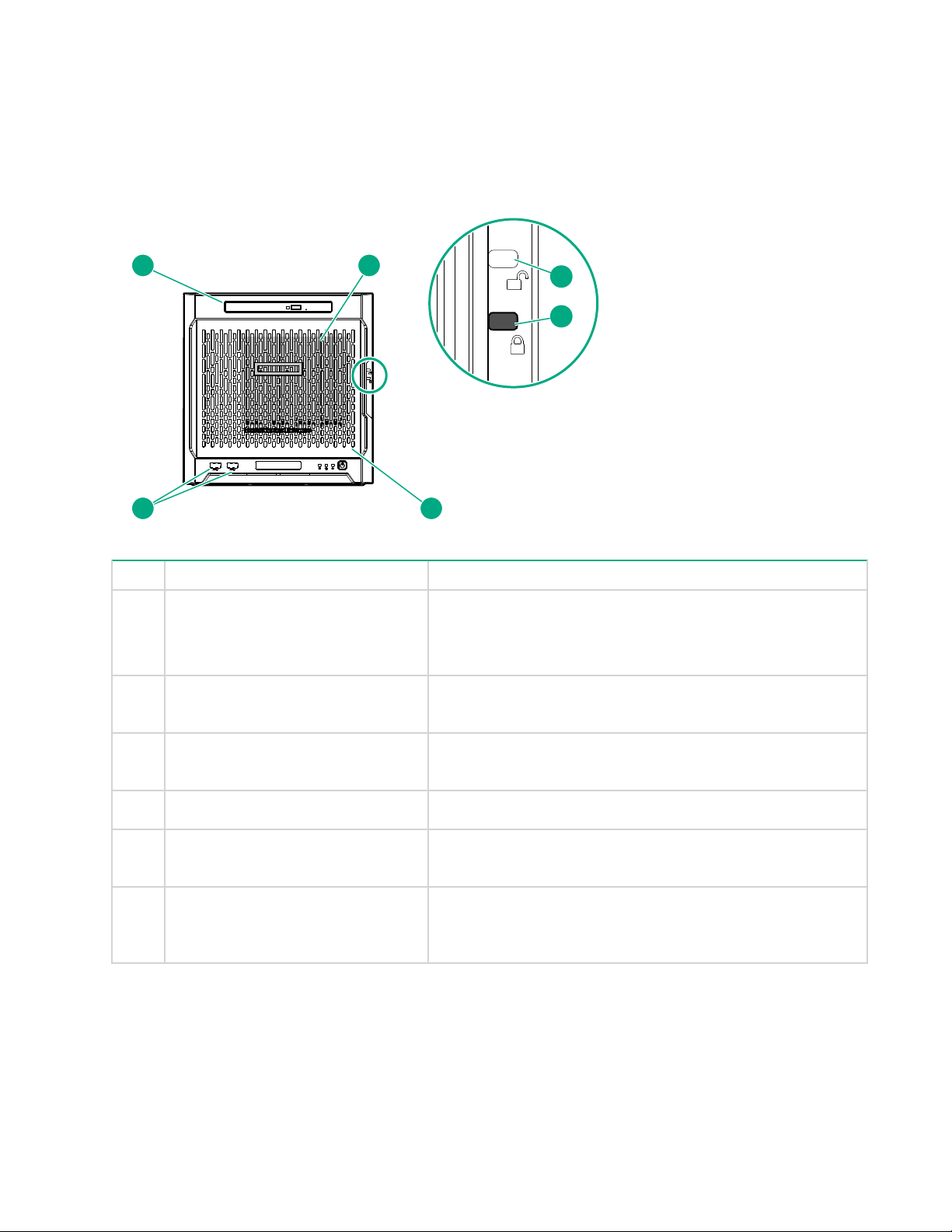
Front panel components
Item Component Description
1 Drive bays (4, behind the front
bezel)
2 Front bezel unlock indicator To remove the front bezel from the chassis, this groove must
3 Front bezel lock indicator To lock the front bezel in the chassis, this groove must show
4 Front bezel To access the front drive bays, remove this bezel.
5 USB 3.0 ports (2) Connect USB 3.0 devices to these ports. USB 3.0 support
6 Media bay When the relevant enablement options kits are installed, this
By default, the drive bays support 3.5-inch LFF SATA drives.
To support 2.5-inch SFF drives, install the SFF drive converter
option.
show the blue indicator.
the blue indicator.
after POST varies by operating system.
bay supports either a slim-type optical disc drive or solid state
drive option.
6 Component identification
Page 7
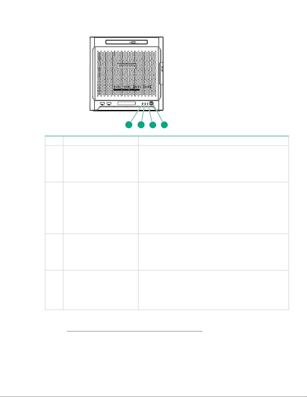
Front panel LEDs and buttons
1 2
3
4
Item Description Status
1 Drive activity LED Flashing green = Ongoing drive activity
Off = No drive activity
This LED only reflects the status of LFF/SFF drives and SSD that
are connected to the onboard SATA ports.
2 NIC status LED Solid green = Linked to network
Flashing green = Network active
Off = No network activity
This LED only reflects the status of Ethernet connections
managed by the embedded Broadcom BCM5720 Gigabit Ethernet
controller.
3 Health LED Solid green = Normal
Flashing amber = One or more component is in degraded
condition.
1
Flashing red = One or more component is in critical condition.
4 Power on/Standby button and
system power LED
Flashing green = Ongoing power-on sequence
Solid green = System on and normal operation
Amber = System in standby
Off = No power present
1
To identify which component is in the degraded or critical state, reboot the server. A POST error message
2
screen showing the affected component will appear for about 30 seconds. Depending on how critical the
component health status is, the system boot may or may not be completed. For troubleshooting information,
see the HPE ProLiant MicroServer Gen10 Troubleshooting Guide.
2
If the server does not power on, verify the following items:
1
Front panel LEDs and buttons 7
Page 8
Item Description Status
1
3
4
567
9
10
11
2
12
8
• The site power is available.
• The power cord is properly connected to the server power jack and to a working power source.
• The internal power supply cable is properly connected to the system board.
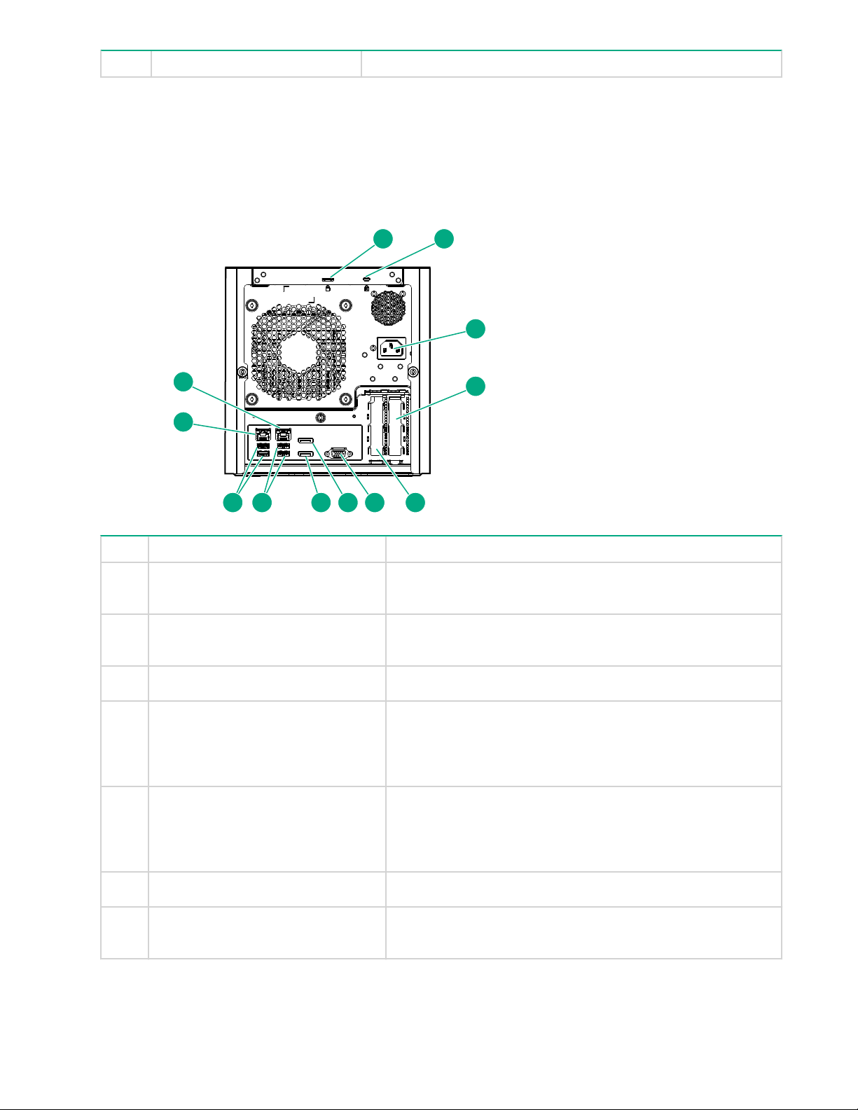
Rear panel components
Item Component Description
1 Padlock eye To lock the chassis cover and prevent access to the internal
components, attach a padlock here.
2 Kensington security slot To secure the server to a heavy or immovable object, connect
an anti-theft security cable here.
3 Power jack Connects the power cord.
4 Expansion slot 2, PCIe3 ×4 (1) For additional hardware capabilities, install a compatible
low‑profile PCIe expansion board here. This expansion slot
supports expansion boards with a physical connector link
widths of up to ×16.
1
5 Expansion slot 1, PCIe3 ×8 (8, 4, 1) For additional hardware capabilities, install a compatible
low‑profile PCIe expansion board here. This expansion slot
supports expansion boards with a physical connector link
widths of up to ×16.
6 Video port
7 Display port 1 Connects to a digital display device, such as a high-resolution
Connects to an analog VGA monitor or projector.
set top boxes or TV displays.
1
2
8 Rear panel components
Table Continued
Page 9
Item Component Description
21
8 Display port 2 Connects to a digital display device, such as a high-resolution
9 USB 2.0 ports (2)
10 USB 3.0 ports (2)
11 NIC port 1 (1 Gb) Connect an Ethernet cable here to connect the server to a
12 NIC port 2 (1 Gb) Connect an Ethernet cable here to connect the server to a
1
This expansion slot is open-ended, which enables down-plugging. Down-plugging means a larger
expansion board can be installed in a smaller
low-profile expansion boards with a physical connector link width of up to ×16. The board operates at the
highest common negotiable link width specified for the slot.
2
To support 4K resolution at a full 60 Hz frame rate, this Display port requires dual-channel memory
configuration. Single-channel memory configuration will only support up to 30 Hz frame rate.
3
This NIC port supports 10/100/1000 Mbps data transfer rate per port.
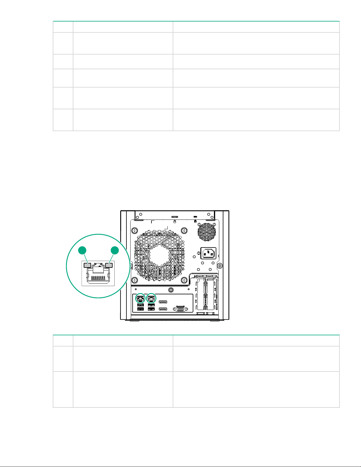
Rear panel LEDs
set top boxes or TV displays.
2
Connect USB 2.0 devices to these ports.
Connect USB 3.0 devices to these ports. USB 3.0 support
after POST varies by operating system.
wired network.
wired network.
3
3
-width
-width connector. For this server, the expansion slot supports
Item Description Status
1 NIC link LED Solid green = Link exists
Off = No link exists
2 NIC status LED Solid green = Linked to network
Flashing green = Network active
Off = No network activity
Rear panel LEDs 9
Page 10
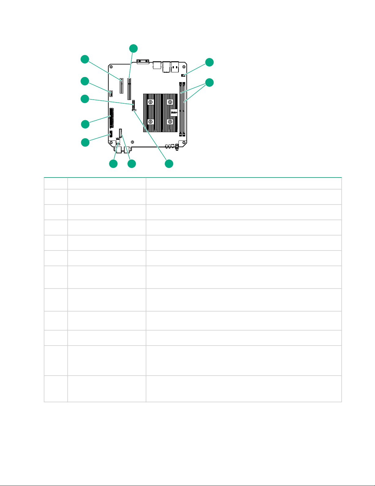
System board components
4
5
6
11
1
2
3
7
8
9
10
Item Component Description
1 Fan connector
2 DIMM slots
3 CMOS header
4 TPM connector
5 LFF/SFF drive SATA port
6 Optical drive or SSD SATA
Connects the fan cable.
These slots support standard UDIMMs with ECC only.
Use the jumper on this header to clear the CMOS.
This connector supports the TPM 2.0 option for data security solution.
Connects the LFF/SFF drive SATA cable.
Connects the optical drive or SSD SATA cable.
port
7 System board power
Connects the power supply cable.
connector
8 System battery
This battery provides power to the server real-time clock and BIOS
settings.
9 Internal USB 2.0 port
10 Expansion slot 2, PCIe3
×4 (1)
11 Expansion slot 1, PCIe3
1
This expansion slot is open-ended, which enables down-plugging. Down-plugging means a larger-width
expansion board can be installed in a smaller
×8 (8, 4, 1)
Connect internal USB devices to this port.
For additional hardware capabilities, install a compatible low-profile
PCIe expansion board here. This expansion slot supports expansion
boards with a physical connector link widths of up to ×16.
1
For additional hardware capabilities, install a compatible low-profile
PCIe expansion board here. This expansion slot supports expansion
boards with a physical connector link widths of up to ×16.
1
-width connector. For this server, the expansion slot supports
low-profile expansion boards with a physical connector link widths of up to ×16. The board operates at the
highest common negotiable link width specified for the slot.
10 System board components
Page 11

PCIe slot description
PCIe3 x8 (8,4,1)
PCIe slot description
1
2 3
Item Description Definition
1 PCI Express version
2 Physical connector link width PCIe devices communicate via a logical connection
3 Negotiable link width These numbers correspond to the maximum link
Each PCIe version corresponds to a specific data
transfer rate between the processor and peripheral
devices. Generally, a version update corresponds to an
increase in transfer rate.
• PCIe 1.x
• PCIe 2.x
• PCIe 3.x
The PCIe technology is under constant development. For
the latest information, see the PCI-SIG website.
called an interconnect or link. At the physical level, a link
is composed of one or more lanes. The number of lanes
is written with an "×" prefix with ×16 being the largest
size in common use.
• ×1
• ×2
• ×4
• ×8
• ×16
bandwidth supported by the slot.
DIMM slot locations
The DIMM slots are numbered 1 and 2. The arrow in the following illustration points to the front of the server.
PCIe slot description 11
Page 12
1A 2B
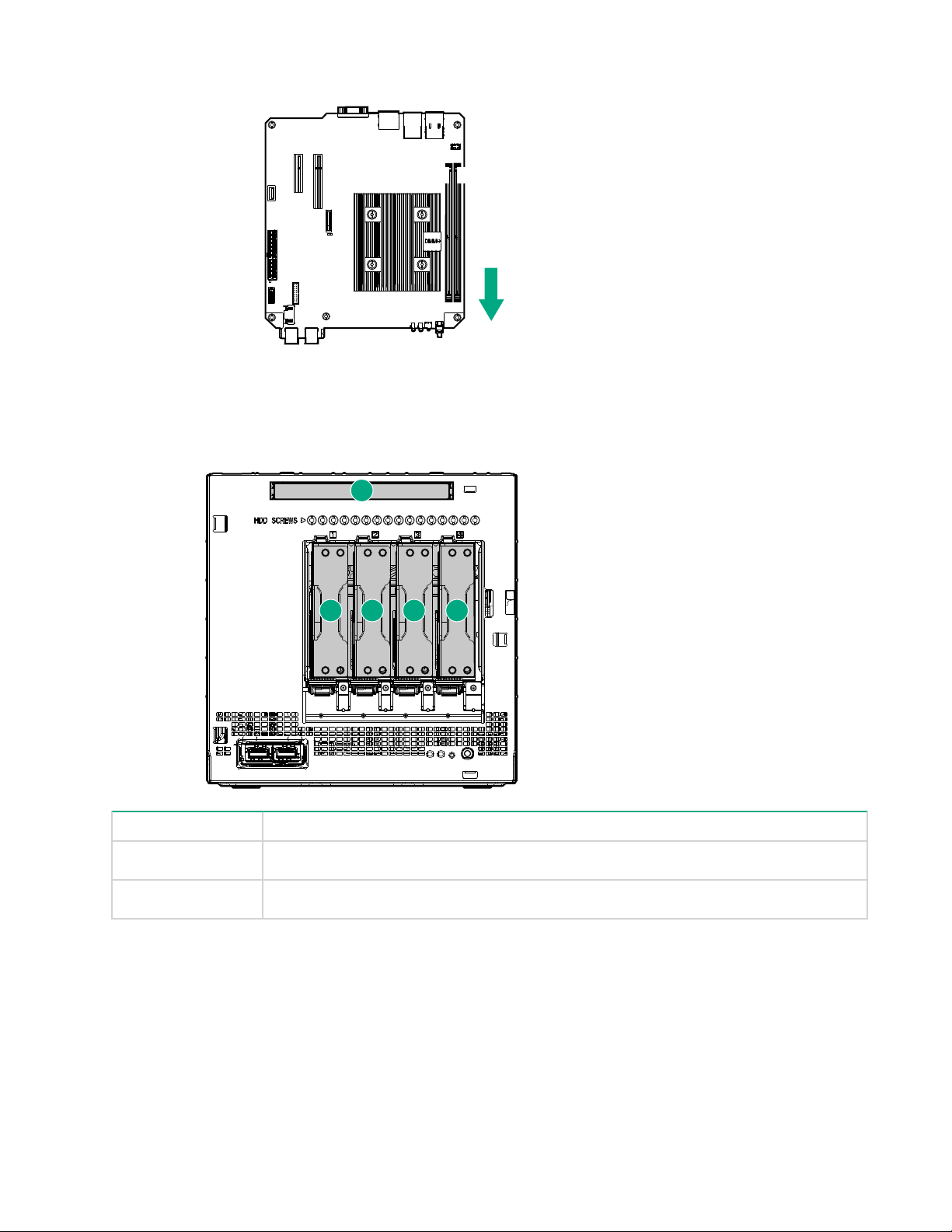
Drive numbering
1 2
5
3 4
Item Description
1-4 LFF/SFF drives
5 Solid state drive or optical disc drive
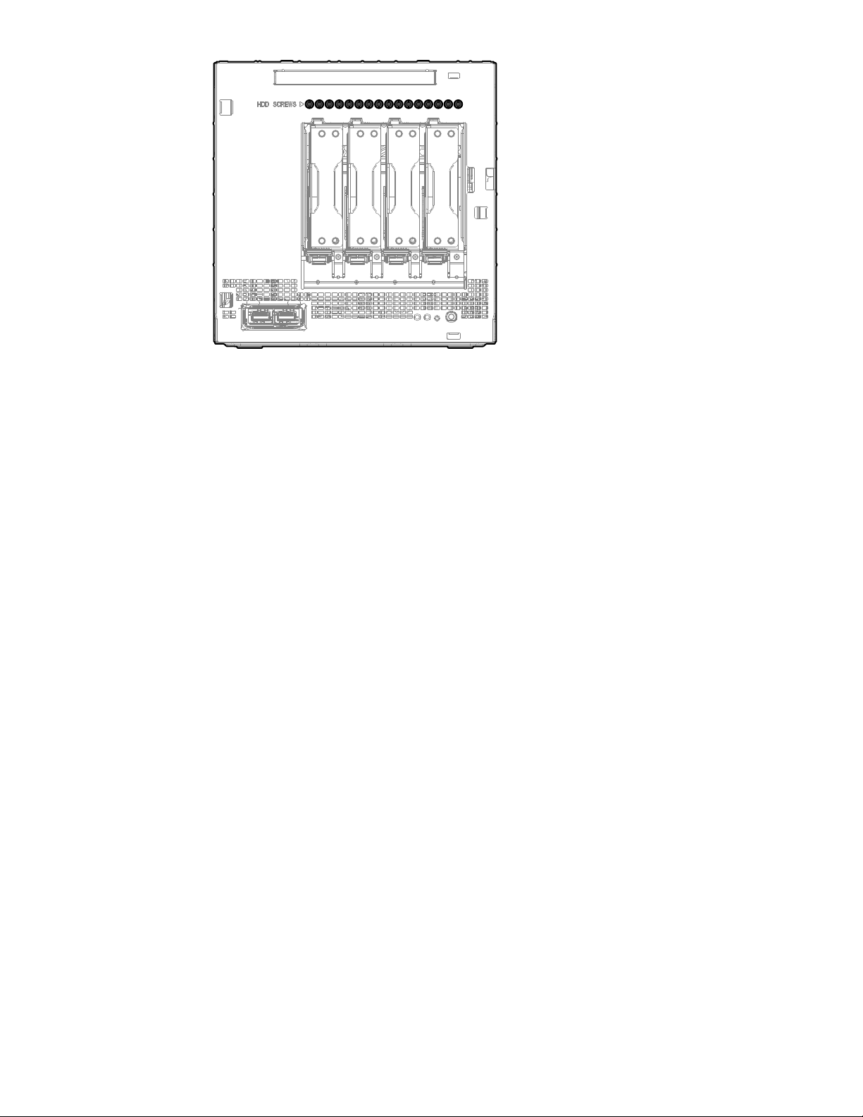
Drive screws
There are 16 T-15 T
the server.
12 Drive numbering
orx screws located above the drive bays. Use these screws to install LFF or SFF drives in
Page 13
Component identification 13
Page 14

Setup
This chapter describes the initial setup procedures to prepare the server for operation.
Optional services
Delivered by experienced, certified engineers, HPE support services help you keep your servers up and
running with support packages tailored specifically for HPE ProLiant systems. HPE support services let you
integrate both hardware and software support into a single package. A number of service level options are
available to meet your business and IT needs.
HPE support services offer upgraded service levels to expand the standard product warranty with
‑to‑buy, easy‑to‑use support packages that will help you make the most of your server investments.
easy
Some of the HPE support services for hardware, software, or both are:
• Foundation Care – Keep systems running.
The time commitment for this service might vary depending on the site's geographical region. For more
service information available at your site, contact your local
• Deployment service for both hardware and software.
HPE Education Services – Help train your IT staff.
•
For more information on HPE support services, see the HPE Pointnext website:
http://www.hpe.com/services
HPE support center.
Initial server setup overview
Procedure
1. Unpack the server shipping carton.
2. If applicable, install any hardware options that are shipped separately from the server.
For detailed option installation instructions, see the relevant section in Hardware options installation on
page 31.
3. Review the initial server setup prerequisites.
4. Connect the I/O devices.
5. Connect the network cable.
6. Connect the power cord.
7. Power on the server for the first time.
8. Install an operating system (OS).
9. As a best practice, Hewlett Packard Enterprise recommends that you install the latest firmware,
drivers, and system software before using the server for the first time.
10. Register the server.
Unpacking the server shipping carton
Unpack the server shipping carton. The contents of the server shipping carton include:
Server
•
•
Power cord
• Printed setup documentation
14 Setup
Page 15

Prerequisites for the initial server setup
Procedure
Verify that the optimum environmental requirements are satisfied.
Review and observe the server warnings and cautions.
Prepare the following items:
◦ Keyboard, mouse, and monitor
Ethernet cables of an appropriate length for each of the LAN and/or WAN connections.
◦
◦ Verify the network settings needed to integrate the server into the site network, in particular from an IP
addressing perspective and from a domain perspective.
◦ Verify that there are sufficient ports available on the devices to which the server will be connected (for
example, router, LAN switch).
Optimum environment
When installing the server, select a location that meets the environmental requirements described in this
section.
Site requirements
The server may be located in an office space or a purpose-made equipment room. The location must:
• Comply with local health and safety regulations.
• Be clean, tidy, and free of excessive dust and vibration.
• Be in an area in which the server cannot easily be disconnected from its power source.
• Not be adjacent to or underneath any area or piece of equipment where liquid is stored.
• Not be in a place where the server might be bumped, scratched, or disturbed.
• Be within an area that is ideally locked or at minimum not accessible to unauthorized personnel.
• Be within patching distance, directly or via cable management cross-patches, of the location of the WAN
connection and the switch that supplies the office/room floor network ports.
Space and airflow requirements
Leave at least a 10 cm (4 in) clearance space at the front and back of the server for proper ventilation.
CAUTION:
The server draws in cool air through the ventilation openings on the front side, and expels warm air
through the ventilation openings on the rear side. Do not block these openings. Failure to observe this
caution will result in improper airflow and insufficient cooling that can lead to thermal damage.
Temperature requirements
To ensure continued, safe, and reliable equipment operation, install or position the system in a well-ventilated,
climate-controlled environment.
The maximum recommended TMRA for most server products is 35°C (95°F). The temperature in the room
where the server is located must not exceed 35°C (95°F).
Prerequisites for the initial server setup 15
Page 16

CAUTION:
To reduce the risk of damage to the equipment when installing third-party options:
Do not permit optional equipment to impede airflow around the server beyond the maximum
•
allowable limits.
• Do not exceed the manufacturer’s TMRA.
Power requirements
Installation of this equipment must comply with local and regional electrical regulations governing the
installation of information technology equipment by licensed electricians. This equipment is designed to
operate in installations covered by NFPA 70, 1999 Edition (National Electric Code) and NFP
for Protection of Electronic Computer/Data Processing Equipment). For electrical power ratings on options,
see the product rating label or the user documentation supplied with that option.
CAUTION:
Protect the server from power fluctuations and temporary interruptions with a regulating uninterruptible
power supply. This device protects the hardware from damage caused by power surges and voltage
spikes and keeps the system in operation during a power failure.
When installing more than one server, you might have to use additional power distribution devices to safely
provide power to all devices. Observe the following guidelines:
• Balance the server power load between available AC supply branch circuits.
Do not allow the overall system AC current load to exceed 80% of the branch circuit AC current rating.
•
• Do not use common power outlet strips for this equipment.
• Provide a separate electrical circuit for the server.
A-75, 1992 (code
Electrical grounding requirements
The server must be grounded properly for proper operation and safety. In the United States, you must install
the equipment in accordance with NFP
local and regional building codes. In Canada, you must install the equipment in accordance with Canadian
Standards Association, CSA C22.1, Canadian Electrical Code. In all other countries, you must install the
equipment in accordance with any regional or national electrical wiring codes, such as the International
Electrotechnical Commission (IEC) Code 364, parts 1 through 7. Furthermore, you must be sure that all
power distribution devices used in the installation, such as branch wiring and receptacles, are listed or
certified grounding-type devices.
Because of the high ground-leakage currents associated with multiple servers connected to the same power
source, Hewlett Packard Enterprise recommends the use of a PDU that is either permanently wired to the
building’s branch circuit or includes a nondetachable cord that is wired to an industrial-style plug. NEMA
locking-style plugs or those complying with IEC 60309 are considered suitable for this purpose. Using
common power outlet strips for the server is not recommended.
A 70, 1999 Edition (National Electric Code), Article 250, as well as any
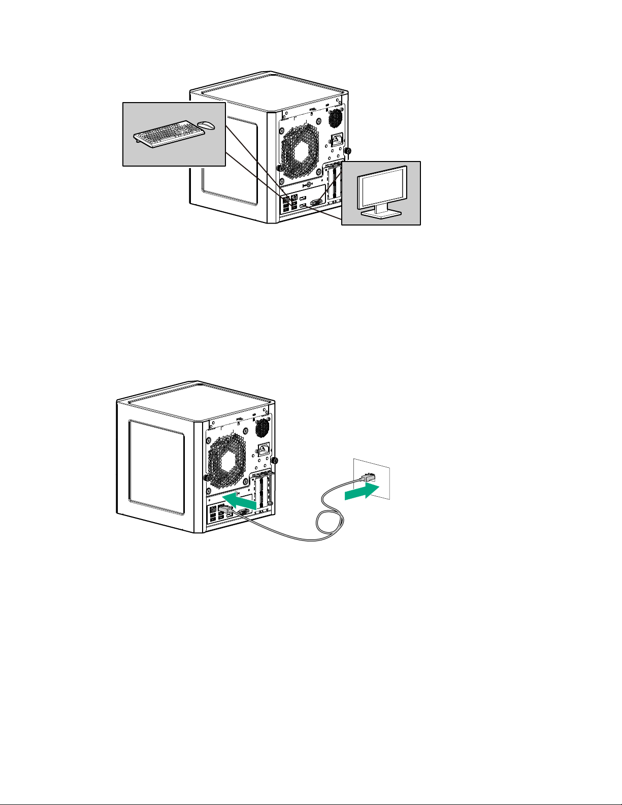
Connecting the I/O devices
About this task
To view and navigate the initial server setup screens, connect I/O devices to the server.
Procedure
1. Connect a keyboard and mouse to the USB ports.
2. Connect a monitor to the VGA or Display port.
16 Power requirements
Page 17
Connecting the network cable
Procedure
1. Connect one end of the network cable to the NIC port.
2. Connect the other end of the network cable to a network jack or a network device such as router or LAN
switch.
Connecting the network cable 17
Page 18
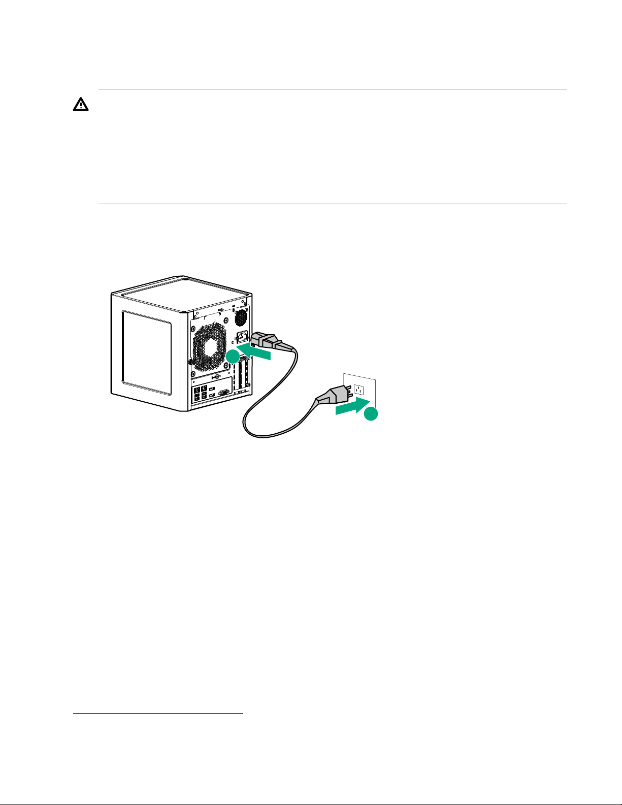
Connecting the power cord
1
2
About this task
WARNING:
To reduce the risk of electric shock or damage to the equipment:
Do not disable the power cord grounding plug. The grounding plug is an important safety feature.
•
• Plug the power cord into a grounded (earthed) electrical outlet that is easily accessible at all times.
• Unplug the power cord from the power supply to disconnect power to the equipment.
• Do not route the power cord where it can be walked on or pinched by items placed against it. Pay
particular attention to the plug, electrical outlet, and the point where the cord extends from the server.
Procedure
1. Connect the power cord to the server power jack.
2. Connect the power cord to the AC power source.
Powering on the server for the first time
Procedure
1. If you are installing an operating system from a bootable media, insert the media into the server.
2. Press the Power On/Standby button.
3. Verify that the system power LED changes to green.
4. During the initial boot, on the enter setup prompt, press the F2 or Del key to access the Aptio Setup Utility
and do one of the following:
• Modify the default BIOS configuration settings.
• Access the preloaded ClearOS image.
• Adjust the boot order to select the OS bootable media.
Installing an operating system
To operate properly
operating systems, see the Hewlett Packard Enterprise website:
http://www.hpe.com/info/supportos
18 Connecting the power cord
, the server must have a supported operating system. For information on supported
Page 19

This server supports Class 2 UEFI implementation. UEFI Class 2 implementation supports both UEFI boot
mode and legacy BIOS boot mode. The boot mode is configured in the Aptio Setup Utility. When the server is
configured for UEFI boot mode, observe the appropriate operating system, boot mode, network device, and
controller requirements. For more information on these requirements, see the Important UEFI Requirements
(for the HPE ProLiant MicroServer Gen10) on the Hewlett Packard Enterprise Information Library:
http://www.hpe.com/info/UEFI/docs
To install an operating system on the server
• If you are planning to install ClearOS, there are two install scenarios:
◦ For a server that shipped with ClearOS,
◦ For a server that does not have ClearOS preloaded, download the software from the Hewlett Packard
Enterprise website:
http://www.hpe.com/servers/clearos
ClearOS is a Linux-based OS with a web-based interface with its own application marketplace for small to
medium businesses. For detailed ClearOS installation instructions, see the ClearOS 7 on HPE ProLiant
Servers Installation Guide at:
http://www.hpe.com/support/ClearOS-IG
• If you are planning to install another OS, boot directly from the OS installation media.
This installation media can either be an optical disc or a USB drive. If you are using an OS installation disc
and the server does not have an internal optical drive installed, an external USB optical drive is required.
, use one of the following methods:
Install the preloaded ClearOS image
Procedure
1. On the Aptio Setup Utility screen, select the Boot menu.
2. Under Boot Option Priorities, verify that Boot Option #1 is set as [ClearOS Utilities].
If it is not set, select Boot Option #1, press the Enter key, and then change the setting to [ClearOS
Utilities].
o confirm the change and exit the utility, press the F4 key.
3. T
boot the server to the preloaded ClearOS image.
The server automatically reboots to the selected device.
4. Follow the OS installation wizard instructions.
Install an OS from a bootable installation media
Procedure
1. On the Aptio Setup Utility screen, select the Boot menu.
2. Under Boot Option Priorities, verify that Boot Option #1 is set to the OS installation media device.
If it is not set, select Boot Option #1, press the Enter key, and then change the setting.
o confirm the change and exit the utility, press the F4 key.
3. T
The server automatically reboots to the selected device.
4. Follow the OS installation wizard instructions.
Installing the latest system software and firmware
As a best practice, Hewlett Packard Enterprise recommends that you install the latest firmware, drivers, and
system software before using the
see the server download page:
server for the first time. T
o get the latest firmware and software updates,
Install the preloaded ClearOS image 19
Page 20

http://www.hpe.com/downloads/microservergen10
Registering the server
To experience quicker service and more ef
https://myenterpriselicense.hpe.com/
ficient support, register the server at the My License Portal website:
20 Registering the server
Page 21
Operations
This chapter describes the hardware operations carried out prior to and after installing or removing a
hardware option, or performing a server maintenance or troubleshooting procedure.
Before performing these hardware operations, review and observe the server warnings and cautions.
Server warnings and cautions
WARNING:
To reduce the risk of personal injury
cord to remove power from the server. Pressing the Power On/Standby button does not shut off system
power completely. Portions of the power supply and some internal circuitry remain active until AC power
is removed.
WARNING:
To reduce the risk of personal injury from hot surfaces, allow the drives and the internal system
components to cool before touching them.
CAUTION:
Protect the server from power fluctuations and temporary interruptions with a regulating UPS. This
device protects the hardware from damage caused by power surges and voltage spikes and keeps the
server in operation during a power failure.
CAUTION:
To prevent improper cooling and thermal damage, do not operate the server with the media bay blank,
chassis cover
CAUTION:
To prevent damage to electrical components, properly ground the
installation procedure. Improper grounding can cause electrostatic discharge.
, or the front bezel removed.
, electric shock, or damage to the equipment, disconnect the power
server before beginning any
CAUTION:
To avoid data loss, Hewlett Packard Enterprise recommends that you back up all server data before
installing or removing a hardware option, or performing a server maintenance or troubleshooting
procedure.
Electrostatic discharge
Preventing electrostatic discharge
About this task
To prevent damaging the system, be aware of the precautions you must follow when setting up the system or
handling parts. A discharge of static electricity from a finger or other conductor may damage system boards or
other static-sensitive devices. This type of damage may reduce the life expectancy of the device.
Operations 21
Page 22

Procedure
• Avoid hand contact by transporting and storing products in static-safe containers.
• Keep electrostatic-sensitive parts in their containers until they arrive at static-free workstations.
Place parts on a grounded surface before removing them from their containers.
•
• Avoid touching pins, leads, or circuitry.
• Always be properly grounded when touching a static-sensitive component or assembly.
Grounding methods to prevent electrostatic discharge
Several methods are used for grounding. Use one or more of the following methods when handling or
installing electrostatic-sensitive parts:
• Use a wrist strap connected by a ground cord to a grounded workstation or computer chassis. Wrist straps
are flexible straps with a minimum of 1 megohm ±10 percent resistance in the ground cords. To provide
proper ground, wear the strap snug against the skin.
•
Use heel straps, toe straps, or boot straps at standing workstations. Wear the straps on both feet when
standing on conductive floors or dissipating floor mats.
• Use conductive field service tools.
• Use a portable field service kit with a folding static-dissipating work mat.
If you do not have any of the suggested equipment for proper grounding, have an authorized reseller install
the part.
For more information on static electricity or assistance with product installation, contact an authorized reseller.
Power up the server
Press the Power On/Standby button.
The server exits standby mode and applies full power to the system. The system power LED changes to
green.
Power down the server
Prerequisites
Before powering down the server for any upgrade or maintenance procedures, perform a backup of critical
server data and programs.
Procedure
• Press and release the Power On/Standby button.
This method initiates a controlled shutdown of applications and the OS before the server enters standby
mode.
• Press and hold the Power On/Standby button for more than 4 seconds to force the server to enter standby
mode.
This method forces the server to enter standby mode without properly exiting applications and the OS. If
an application stops responding, you can use this method to force a shutdown.
The system power LED changes to red indicating that the server is in standby mode. Auxiliary power is still
present in the system in this mode.
22 Grounding methods to prevent electrostatic discharge
Page 23

Prepare the server for hardware installation or removal
Procedure
1. Power down the server on page 22.
2. Disconnect the power cord from the AC source, and then from the server.
3. Disconnect all peripheral cables from the server
4. If installed, unlock and remove the security padlock and/or the Kensington security lock.
For more information, see the lock documentation.
.
Prepare the server for operation
Procedure
1. If removed, attach the security padlock and/or the Kensington security lock.
For more information, see the lock documentation.
2. Connect all peripheral cables to the server.
3. Connect the power cord to the server power jack, and then to the AC source.
4. Secure the power cord and rear panel cables based on the standard cable management practices.
5. Power up the server on page 22.
Remove the front bezel
o access the drive bays, remove the front bezel.
T
Removing a locked front bezel
Prerequisites
1. Power down the server on page 22.
2. Disconnect the power cord from the AC source, and then from the server
3. Disconnect all peripheral cables from the server.
4.
Remove the chassis cover on page 26.
Procedure
1. To unlock the front bezel from the chassis, slide the release tab upward.
.
Prepare the server for hardware installation or removal 23
Page 24

1
2. Open the front bezel.
1
2
3. To completely detach the bezel from the front panel, release the bezel hinges from the chassis.
Retain the bezel for later use.
Removing an unlocked front bezel
Prerequisites
1. Power down the server on page 22.
2. Disconnect the power cord from the AC source, and then from the server
3. Disconnect all peripheral cables from the server.
Procedure
1. Open the front bezel.
2. To completely detach the bezel from the front panel, release the bezel hinges from the chassis.
Retain the bezel for later use.
24 Removing an unlocked front bezel
.
Page 25

1
2
Install the front bezel
1
2
About this task
To cover the drive bays, install the front bezel.
Procedure
1. Attach the bezel to the front panel, and then close it.
2. If you prefer to secure the bezel to the chassis, do the following:
a. If installed, remove the chassis cover.
b. Slide the release tab downwards to lock the bezel to the chassis.
Install the front bezel 25
Page 26

c. Install the chassis cover on page 27.
1
1
2
Remove the chassis cover
About this task
To access the front bezel lock and the internal components, remove the chassis cover.
Procedure
1. If installed, unlock and remove the security padlock and/or the Kensington security lock.
For more information, see the lock documentation.
2. Remove the chassis cover thumbscrews.
If the thumbscrews are too tight, use a T-15 screwdriver to remove it.
3. Slide the chassis cover toward the rear panel, and then lift it from the server.
26 Remove the chassis cover
Page 27

Install the chassis cover
1
1
3
3
2
To prevent access to the front bezel lock and the internal components, install the chassis cover.
Install the chassis cover
Prerequisites
1. Verify that all internal cables are properly connected and are secured in their respective cable ties.
erify that the drive cables are not blocking the fan blades.
2. V
Procedure
1. Insert the tabs on the bottom left and right sides of the chassis cover into the corresponding slots on the
chassis.
2. Slide the chassis cover towards the front panel.
3. Install the chassis thumbscrews.
4. If removed, install the security padlock and/or the Kensington security lock.
For more information, see the lock documentation.
Install the system board assembly
To secure the system board inside the chassis, install the system board assembly.
Install the system board assembly
Prerequisites
Procedure
Before you perform this procedure, make sure that you have a T-15 T
1. Slide the system board assembly into the chassis.
2. Press against the system board assembly until it clicks into place.
3. Install the system board assembly screw.
orx screwdriver available.
Install the chassis cover 27
Page 28

1
1
2
3
4. Connect the following system cables:
• Power supply cable
• Optical drive or SSD SATA cable (optional)
• LFF/SFF drive SATA cable – This cable can either be connected to the system board or to an installed
HBA.
• Fan cable
5. If removed, install the internal USB device.
Remove the system board assembly
To install or remove hardware components on the system board or to access the CMOS header, remove the
system board assembly
28 Remove the system board assembly
.
Page 29

Remove the system board assembly
1
2
2
1
1
2
Prerequisites
Before you perform this procedure, make sure that you have a T-15 T
Procedure
1. If installed, remove the internal USB device.
2. To serve as a reference for system cable connections when the system board assembly is installed back
3. Disconnect the following system cables:
orx screwdriver available.
into the server
, take a picture of the current system board cable connections.
• Power supply cable
• Optical drive or SSD SATA cable (optional)
• LFF/SFF drive SATA cable – This cable can either be connected to the system board or to an installed
HBA.
• Fan cable
4. Remove the system board assembly screw.
5. Place a finger in the notch on both sides of the system board assembly, and then pull out the assembly.
Remove the system board assembly 29
Page 30

1
2
2
30 Operations
Page 31

Hardware options installation
This chapter provides detailed instructions on how to install hardware options.
For more information on supported options, see the product QuickSpecs on the HPE ProLiant MicroServer
Gen10 website at:
http://www.hpe.com/server/microserver
To view the warranty for your server and supported options, see Warranty information.
Introduction
If more than one option is being installed, read the installation instructions for all the hardware options and
identify similar steps to streamline the installation process.
WARNING:
To reduce the risk of personal injury from hot surfaces, allow the drives and the internal system
components to cool before touching them.
CAUTION:
To prevent damage to electrical components, properly ground the server before beginning any
installation procedure. Improper grounding can cause electrostatic discharge.
Drive support information
This server only supports non-hot-plug drives. These drives are not designed to be installed or removed from
the server while the system is still powered on. Power of
option.
From a drive interface standpoint, the embedded Marvell 88SE9230 PCIe to SAT
SATA drives.
From a form factor standpoint, the server drive bays support 3.5-inch LFF drives. To support 2.5-inch SFF
drives,
To support a 7-mm SA
install the SFF-to-LFF drive converter option.
TA solid state drive in the media bay,
Drive installation guidelines
Populate drive bays based on the drive numbering sequence. Start from the
•
device number.
• All drives grouped into the same drive array must meet the following criteria:
They must be either all hard drives or all solid state drives.
◦
◦ Drives should be the same capacity to provide the greatest storage space efficiency when drives are
grouped together into the same drive array.
• The system automatically sets all device numbers.
Installing an LFF drive
f the server before installing or removing a drive
A 6Gb/s Controller supports
install the SSD enablement kit.
drive bay with the lowest
About this task
To add internal data storage to the server
, install one or more LFF drives in the drive bays.
Hardware options installation 31
Page 32

Procedure
1. Power down the server on page 22.
2. Disconnect the power cord from the AC source, and then from the server.
3. Disconnect all peripheral cables from the server
4.
5. Install the LFF drive on page 32.
6. Install the front bezel on page 25.
7. Connect all peripheral cables to the server
8. Connect the power cord to the server power jack, and then to the AC source.
9.
10. Determine the status of the server drives from the drive LED definitions.
11. T
.
Remove the front bezel on page 23.
.
Power up the server on page 22.
o configure drive arrays, do one of the following:
• If the drives are connected to the LFF/SFF drive SATA port, use the
or the
63
If the drives are connected to an HPE Smart HBA or Smart Array controller option, use the
•
Smart Storage Administrator on page 63.
Marvell BIOS Utility on page 64.
Install the LFF drive
Prerequisites
Before you perform this procedure, make sure that you have the following items available:
-15 Torx screwdriver
• T
• LFF drive option
Procedure
1. Remove four drive screws from the front panel.
Marvell Storage Utility on page
HPE
2. Install the screws in the drive.
32 Install the LFF drive
Page 33

3. Slide the drive into the drive bay until it clicks into place.
Installing an SFF drive
About this task
To install SFF drives in the drive bays, install the SFF drive converter option. In general, SFF drives give
greater power and space savings. SFF drives can require as little as half the power and generate significantly
less heat than LFF drives.
Procedure
1. Power down the server on page 22.
2. Disconnect the power cord from the AC source, and then from the server.
3. Disconnect all peripheral cables from the server
4.
5. Install the SFF drive on page 34.
6. Install the front bezel on page 25.
7. Connect all peripheral cables to the server
8. Connect the power cord to the server power jack, and then to the AC source.
9.
10. Determine the status of the server drives from the drive LED definitions.
11. T
.
Remove the front bezel on page 23.
.
Power up the server on page 22.
o configure drive arrays, do one of the following:
Installing an SFF drive 33
Page 34

• If the drives are connected to the LFF/SFF drive SATA port, use the Marvell Storage Utility on page
or the
63
If the drives are connected to an HPE Smart HBA or Smart Array controller option, use the
•
Smart Storage Administrator on page 63.
Marvell BIOS Utility on page 64.
Install the SFF drive
Prerequisites
Before you perform this procedure, make sure that you have the following items available:
-10 Torx screwdriver
• T
• T-15 Torx screwdriver
• SFF drive converter option kit. This kit includes:
◦ Drive converter tray
◦ T-10 screws (4)
• SFF drive option
Procedure
1. Install the SFF drive in the drive converter tray.
HPE
2. Follow the callout sequence in the following illustration to install the screws included in the converter kit on
the bottom side of the converter tray.
34 Install the SFF drive
Page 35

1
3
2
4
3. Remove three drive screws from the front panel.
4. Install the three screws removed from the front panel on the left and right sides of the converter tray.
Hardware options installation 35
Page 36

5. Slide the drive into the drive bay until it clicks into place.
Installing an SSD
About this task
The media bay supports a 7-mm slim-type SAT
Information is stored in microchips. Traditional hard disk drives use a mechanical arm with a read/write head
to move around and read information from the right location on a rotating storage platters. This lack of rotating
media in SSDs:
• Greatly reduces the SSD’s power consumption
• Enable SSDs to tolerate significantly higher operating shock and vibration levels
SSDs are suitable for server workloads with highly random data under a variety of write-workload
applications.
36 Installing an SSD
A solid state drive option. SSDs have no moving parts.
Page 37

Procedure
1
2
2
2
2
1. Power down the server on page 22.
2. Disconnect the power cord from the AC source, and then from the server.
3. Disconnect all peripheral cables from the server
4.
Remove the chassis cover on page 26.
5. Install the SSD on page 37.
6. Install the chassis cover on page 27.
7. Connect all peripheral cables to the server
8. Connect the power cord to the server power jack, and then to the AC source.
9.
Power up the server on page 22.
Install the SSD
Prerequisites
Before you perform this procedure, make sure that you have the following items available:
-10 Torx screwdriver
• T
• T-15 Torx screwdriver
• SSD enablement option kit. This kit includes:
◦ SSD tray
◦ SSD power cable
◦ SSD SATA cable
◦ T-10 screws (4, for securing the SSD)
◦ T-15 Torx screw (1, for securing the SSD tray)
• SSD option
.
.
Procedure
1. Place the SSD in the SSD tray, and then install the SSD screws.
2. Install the SSD assembly in the media bay, and then secure it with the screw.
Install the SSD 37
Page 38

1
2
3. Connect the SSD power cable:
2
1
a. Open the cable ties.
b. Connect the power cable to the SSD, and then to the power supply cable labeled P3.
38 Hardware options installation
Page 39

1
2
4. Connect the SSD SATA cable:
3
2
2
1
a. Connect the SATA cable to the SSD.
b. Route the SATA cable through the left side chassis opening down to the system board.
c. Connect the SATA cable to the SATA port.
5. Bundle the extra length of the SSD power and SAT
A cables, and then secure them in the cable ties.
Hardware options installation 39
Page 40

1
2
Installing an optical drive
About this task
The media bay supports a slim-type SATA optical drive option. This option allows you to retrieve or store data
on optical discs like CDs and DVDs.
Procedure
1. Power down the server on page 22.
2. Disconnect the power cord from the AC source, and then from the server.
3. Disconnect all peripheral cables from the server.
4. Remove the chassis cover on page 26.
5. Remove the front bezel on page 23.
6. Install an optical drive on page 40.
7. Install the front bezel on page 25.
8. Install the chassis cover on page 27.
9. Connect all peripheral cables to the server.
10. Connect the power cord to the server power jack, and then to the AC source.
11. Power up the server on page 22.
Install an optical drive
Prerequisites
Before you perform this procedure, make sure that you have the following items available:
• T
-15 Torx screwdriver
• Phillips No. 2 screwdriver
• Optical drive option kit. This kit includes:
40 Installing an optical drive
◦ Optical drive
◦ Optical drive bracket
◦ Phillips No. 2 screws (2, for securing the optical drive bracket)
◦ T-15 screw (1, for securing the optical drive)
Page 41

Procedure
2
1
1
1
2
2
1. Facing the server, press and hold the release latches on both sides of the optical drive blank, and then
2. Attach the bracket to the optical drive.
push the blank out of the media bay
Retain the blank for future use.
.
3. Slide the optical drive into the media bay.
4. Install the optical drive screw
.
Hardware options installation 41
Page 42

1
2
5. Connect the optical drive SATA Y-cable:
a. Connect the common end of the cable to the optical drive.
b. Open the cable tie.
42 Hardware options installation
Page 43

2
1
c. Connect the power end of the SATA cable to the power supply cable labeled P3.
d. Route the data end of the SAT
A Y-cable through the left side chassis opening down to the system
board.
e. Connect the data end of the cable to the SATA port.
Hardware options installation 43
Page 44

1
1
2
f. Bundle the extra length of the SATA Y-cable and the power supply P3 cable, and then secure them in
1
2
the cable tie.
Memory support
The server has two DIMM slots supporting standard UDIMMs with ECC for a maximum memory capacity of
32 GB.
For more information on the server memory support, see the Gen10 memory user guide on the Hewlett
Packard Enterprise Information Library:
http://www.hpe.com/info/enterprise-docs
DIMM identification
o determine DIMM characteristics, see the label attached to the DIMM. The information in this section helps
T
you to use the label to locate specific information about the DIMM.
44 Memory support
Page 45

8GB 1R x8 PC 4-240 0T-E
8GB 1 Rx8 PC4 -2400T-E
1 2 43 5 6 7
Item Description Definition
1 Capacity
2 Rank
3 Data width on DRAM
4 Memory generation
5 Maximum memory speed
8 GB
16 GB
32 GB
64 GB
128 GB
1R = Single-rank
2R = Dual-rank
4R = Quad-rank
8R = Octal-rank
x4 = 4-bit
x8 = 8-bit
x16 = 16-bit
PC4 = DDR4
2133 MT/s
2400 MT/s
6 CAS latency
7 DIMM type
2666 MT/s
P = CAS 15-15-15
T = CAS 17-17-17
U = CAS 20-18-18
V = CAS 19-19-19 (for RDIMM, LRDIMM)
V = CAS 22-19-19 (for 3DS TSVLRDIMM)
R = RDIMM (registered)
L = LRDIMM (load reduced)
E = UDIMM (unbuffered ECC)
Hardware options installation 45
Page 46

DIMM ranks
To understand and configure memory protection modes properly
Some DIMM configuration requirements are based on these classifications.
A single-rank DIMM has one set of memory chips that is accessed while writing to or reading from the
memory. A dual-rank DIMM is similar to having two single-rank DIMMs on the same module, with only one
rank accessible at a time. A quad-rank DIMM is, effectively, two dual-rank DIMMs on the same module. Only
one rank is accessible at a time. The server memory control subsystem selects the proper rank within the
DIMM when writing to or reading from the DIMM.
Dual- and quad-rank DIMMs provide the greatest capacity with the existing memory technology. For example,
if current DRAM technology supports 8 GB single-rank DIMMs, a dual-rank DIMM would be 16 GB, and a
quad-rank DIMM would be 32 GB, and an octal-rank LRDIMM would be 64 GB.
LRDIMMs are labeled as quad- and octal-rank DIMMs. There are four and eight ranks of DRAM on the DIMM,
but the LRDIMM buffer creates an abstraction that allows the DIMM to appear as a logical dual-rank DIMM to
the system. This is called Rank Multiplication. The LRDIMM buffer also isolates the electrical loading of the
DRAM from the system to allow for faster operation. These two changes allow the system to support up to
three LRDIMMs per memory channel, providing for greater memory capacity and higher memory operating
speed compared to quad-rank RDIMMs.
DIMM handling guidelines
When handling a DIMM, observe the following guidelines.
• A
void electrostatic discharge.
• Always hold DIMMs by the side edges only.
• Avoid touching the connectors on the bottom of the DIMM.
• Never wrap your fingers around a DIMM.
• Avoid touching the components on the sides of the DIMM.
• Never bend or flex the DIMM.
, an understanding of DIMM rank is helpful.
CAUTION:
Failure to properly handle DIMMs can cause damage to the components on the DIMM, as well as the
system board connector.
DIMM installation guidelines
When installing a DIMM, observe the following guidelines.
• Before seating the DIMM, open the DIMM slot and align the DIMM with the slot.
•
To align and seat the DIMM, use two fingers to hold the DIMM along the side edges.
• To seat the DIMM, use two fingers to apply gentle pressure along the top of the DIMM.
For more information, see the
Hewlett Packard Enterprise website.
Installing a DIMM
About this task
The server uses memory to perform almost all of its operations. Upgrading the server memory capacity leads
to faster boot-up, processing period, and timely responses to promote optimum system performance.
Procedure
1. Power down the server on page 22.
2. Disconnect the power cord from the AC source, and then from the server
.
46 DIMM ranks
Page 47

3. Disconnect all peripheral cables from the server.
2
2
1
4. Remove the chassis cover on page 26.
5. Install the DIMM on page 47.
6. Install the chassis cover on page 27.
7. Connect all peripheral cables to the server
8. Connect the power cord to the server power jack, and then to the AC source.
9.
Power up the server on page 22.
o configure the memory, use the
10. T
Memory Configuration.
Install the DIMM
Procedure
1. Open the DIMM slot latches.
2. Align the notch on the bottom edge of the DIMM with the keyed surface of the DIMM slot, and then fully
press the DIMM into the slot until the latches snap back into place.
The DIMM slots are structured to ensure proper installation. If you try to insert a DIMM but it does not fit
easily into the slot, you might have positioned it incorrectly. Reverse the orientation of the DIMM and insert
it again.
.
Aptio Setup Utility on page 59. Select
Chipset > South Bridge >
Expansion board options
The server has two low-profile, open-ended PCIe3 expansion slots. Use these slots to install additional
hardware capabilities such as:
• An HBA to enable advanced drive features.
A GPU to accelerate the processing speed of your applications.
•
• A network adapter with advanced Ethernet connectivity features.
Installing an expansion board
Procedure
1. Power down the server on page
2. Disconnect the power cord from the AC source, and then from the server.
3. Disconnect all peripheral cables from the server.
4.
22.
Remove the chassis cover on page 26.
Install the DIMM 47
Page 48

5. Remove the system board assembly on page 28.
6. If the expansion board is shipped with an air baffle attached, remove this baffle from the board.
7. If the expansion board is shipped with a full-height bracket attached, replace it with a low-profile one.
8. Install the expansion board.
9. Install the system board assembly on page 27
10. Connect all necessary internal cabling to the expansion board.
For more information on these cabling requirements, see the documentation that ships with the option.
11. Install the chassis cover on page 27.
12. Connect all peripheral cables to the server.
13. Connect the power cord to the server power jack, and then to the AC source.
14. Power up the server on page 22.
Remove the air baffle from the expansion board
Remove the air baffle from the expansion board.
The number and location of the latches that secure the baffle to the board will vary depending on the
expansion board. The illustration below is an example image only. See the expansion board
documentation for model-specific information.
Install a low-profile bracket on the expansion board
About this task
The number and location of the bracket screws will vary depending on the expansion board. The illustrations
below are example images only. See the expansion board documentation for model-specific information.
Procedure
1. Remove the full-height bracket from the expansion board.
48 Remove the air baffle from the expansion board
Page 49

1
2
1
2. Install the low-profile bracket on the expansion board.
1
2
2
Install the expansion board
Prerequisites
Before you perform this procedure, make sure that you have T-15 T
orx screwdriver available.
Procedure
1. Identify the expansion slot compatible with the expansion board, and then remove the blank opposite that
slot.
Retain the blank for future use.
Install the expansion board 49
Page 50

1
2
2. Verify that any switches or jumpers on the expansion board are set properly.
1
2
For more information, see the expansion board documentation.
3. Install the expansion board. Verify that the board is firmly seated in the slot.
Internal USB device options
The server has an internal USB 2.0 port that you can use to install internal USB devices such as:
• USB flash media devices for booting up from flash solutions or for data backup/redundancy.
USB devices that are intended to be rarely removed such as a USB dongle for Bluetooth or Wi‑Fi support.
•
Install an internal USB device
Procedure
1. Power down the server on page 22.
2. Disconnect the power cord from the AC source, and then from the server
3. Disconnect all peripheral cables from the server.
Remove the chassis cover on page 26.
4.
50 Internal USB device options
.
Page 51

5. Plug in the USB device into the internal USB port.
6. Install the chassis cover on page 27.
7. Connect all peripheral cables to the server.
8. Connect the power cord to the server power jack, and then to the AC source.
9. Power up the server on page 22.
For more information on any required setup or configuration procedure, see the USB device documentation.
External HPE RDX Backup System option
To install a simple, inexpensive, and reliable way to securely store your data backups, install an external HPE
RDX Backup System. The backup system is a removable, ruggedized, hard disk drive system.
The backup system consists of two components:
RDX cartridge
•
• RDX docking station
Hewlett Packard Enterprise recommends that no more than one HPE RDX Removable Disk Backup System
be connected to a system at a time.
For more information on installing and configuring the external HPE RDX Removable Disk Backup System,
see the Storage section of the Hewlett Packard Enterprise Information Library:
http://www.hpe.com/info/storage/docs
HP Trusted Platform Module
The TPM is a hardware-based system security feature that can securely store information, such as
passwords and encryption keys, which can be used to authenticate the platform.
The TPM works with Microsoft Windows BitLocker which is a data protection feature available in Microsoft
Windows Server 2008 R2 SP1 and later operating systems. BitLocker helps protect user data and helps
ensure that a server running Windows Server has not been tampered with while the system was offline.
This server supports TPM 2.0. T
cannot be removed from the board once it has been installed.
o prevent possible damage to the TPM or to the system board, the TPM
External HPE RDX Backup System option 51
Page 52

Trusted Platform Module (TPM) — China Import Restrictions
HPE
Special Reminder: Before enabling TPM functionality on this system, you must ensure that your
intended use of TPM complies with relevant local laws, regulations and policies, and approvals or licenses
must be obtained if applicable.
For any compliance issues arising from your operation/usage of the TPM which violates the above mentioned
requirement, you shall bear all the liabilities wholly and solely. HPE will not be responsible for any related
liabilities.
HP Trusted Platform Module installation guidelines
CAUTION:
Always observe the guidelines in this document. Failure to follow these guidelines can cause hardware
damage or halt data access.
When installing or replacing a TPM, observe the following guidelines:
• Do not remove an installed TPM. Once installed, the TPM becomes a permanent part of the system board.
•
When installing or replacing hardware, Hewlett Packard Enterprise service providers cannot enable the
TPM or the encryption technology. For security reasons, only the customer can enable these features.
• When returning a system board for service replacement, do not remove the TPM from the system board.
When requested, HPE Service provides a TPM with the spare system board.
• Any attempt to remove an installed TPM from the system board breaks or disfigures the TPM security
rivet. Upon locating a broken or disfigured rivet on an installed TPM, administrators should consider the
system compromised and take appropriate measures to ensure the integrity of the system data.
• When using BitLocker, always retain the recovery key/password. The recovery key/password is required to
enter Recovery Mode after BitLocker detects a possible compromise of system integrity.
• HPE is not liable for blocked data access caused by improper TPM use. For operating instructions, see the
encryption technology feature documentation provided by the operating system.
Installing the Trusted Platform Module overview
Procedure
1. Installing the Trusted Platform Module board on page 52.
2. Retain the recovery key/password.
3. Enabling the Trusted Platform Module on page 54.
Installing the Trusted Platform Module board
Procedure
1. Power down the server on page
2. Disconnect the power cord from the AC source, and then from the server
3. Disconnect all peripheral cables from the server.
Remove the chassis cover on page 26.
4.
52 Trusted Platform Module (TPM) — China Import Restrictions
22.
Page 53

5. Remove the system board assembly on page 28.
6. Install the Trusted Platform Module board on page 53.
7. Install the system board assembly on page 27.
8. Install the chassis cover on page 27.
9. Connect all peripheral cables to the server
10. Connect the power cord to the server power jack, and then to the AC source.
11.
Power up the server on page 22.
Install the Trusted Platform Module board
Procedure
1. Locate the TPM connector on the system board.
2. Install the TPM board.
.
3. Install the TPM security rivet by pressing the rivet firmly into the system board.
Install the Trusted Platform Module board 53
Page 54

Retaining the recovery key/password
About this task
The recovery key/password is generated during BitLocker setup, and can be saved and printed after
BitLocker is enabled. When using BitLocker, always retain the recovery key/password. The recovery key/
password is required to enter Recovery Mode after BitLocker detects a possible compromise of system
integrity
To help ensure maximum security, observe the guidelines listed in the following procedure list when retaining
the recovery key/password.
Procedure
• Always store the recovery key/password in multiple locations.
•
• Do not save the recovery key/password on the encrypted hard drive.
.
Always store copies of the recovery key/password away from the server.
Enabling the Trusted Platform Module
Procedure
1. To access the Aptio Setup Utility
2. Select Advanced > Trusted Computing, and then press the Enter key.
3. Verify that the TPM device name is displayed.
4. To exit the utility, press the Esc key.
The server reboots without user input. During this system reboot, the TPM is enabled.
5. Enable TPM functionality in the OS, such as Microsoft Windows BitLocker or measured boot.
CAUTION:
When a TPM is installed and enabled on the server, data access is locked if you fail to follow the
proper procedures for updating the system or option firmware, replacing the system board, replacing
a hard drive, or modifying OS application TPM settings.
For more information on adjusting TPM usage in BitLocker, see the Microsoft website:
http://technet.microsoft.com/en-us/library/cc732774.aspx
, on the enter setup prompt, press the F2 or Del key.
54 Retaining the recovery key/password
Page 55

Cabling
1
1
2
2
3
3
Cabling overview
This section provides guidelines that help you make informed decisions about cabling the server and
hardware options to optimize performance.
CAUTION:
When routing cables, always be sure that the cables are not in a position where they can be pinched or
crimped.
Four-bay non-hot-plug drive cabling
The four-bay non-hot-plug drive cable assembly consists of the drive power and SAT
bracket. If either the drive power or SATA cable becomes defective, the entire cable assembly will need to be
replaced.
• LFF/SFF drive SATA cable connected to the system board
Item Description
A cables attached to a
1 P2 power supply cable
2 LFF/SFF drive power cable
3 LFF/SFF drive SATA cable
• LFF/SFF drive SATA cable connected to an HBA
Cabling 55
Page 56

3
3
1
1
2
2
Item Description
1
2
3
1 P2 power supply cable
2 LFF/SFF drive power cable
3 LFF/SFF drive SATA cable
Solid state drive cabling
Item Description
1 SSD power cable
2 P3 power supply cable
3 SSD SATA cable
56 Solid state drive cabling
Page 57

Optical drive cabling
2
3
1
Item Description
1 Optical drive power cable
2 Optical drive SATA cable
3 P3 power supply cable
Fan cabling
Optical drive cabling 57
Page 58

Power supply cabling
1
2
2
3
Item PSU cable marker Description
1 P1 System board power cable
2 P2 LFF/SFF drive power cable
3 P3 Optical drive/SSD power cable
58 Power supply cabling
Page 59

Software and configuration utilities
Server mode
Software or configuration utility Server mode
Aptio Setup Utility Offline
HPE Smart Storage Administrator Online and offline
Marvell Storage Utility Online
Marvell BIOS Utility Offline
Product QuickSpecs
For more information about product features, specifications, options, configurations, and compatibility, see the
product QuickSpecs on the
http://www.hpe.com/server/microserver
Aptio Setup Utility
The Aptio Setup Utility is embedded in the system ROM. This utility enables you to perform a wide range of
configuration activities, including the following:
HPE ProLiant MicroServer Gen10 website:
• Configuring system devices and installed options
Enabling and disabling system features
•
• Displaying system information
• Selecting the primary boot controller
• Configuring memory options
Using the Aptio Setup Utility
To use the Aptio Setup Utility
Key Action
F2 or Del (during POST) Access the Aptio Setup Utility.
Left and right arrows Navigate the menus.
Up and down arrows Navigate menu items.
Enter Select menu items.
F4 Save selections and exit the utility.
F1 Access help for the highlighted configuration option.
Esc Exit the utility.
Default configuration settings are applied to the server in either of the following scenarios:
, use the following keys:
• When the system powers up for the first time
When the system is restored to the default settings
•
Software and configuration utilities 59
Page 60

Default configuration settings are sufficient for typical server operations. However, you can modify the
configuration settings as needed. The system prompts you to access the Aptio Setup Utility every time the
system is powered up.
Boot option control
This feature enables you:
• T
o choose the boot mode, select Advanced > Boot Option.
• To set the boot option priority, select Boot > Boot Option Priorities.
• To select the one time boot option, select Save & Exit > Boot Override.
This menu allows you to select the boot device for a specific boot and does not modify the boot order
configuration settings.
To select the one time boot option directly during POST, press the F11 key when prompted during system
boot, and then select the preferred boot device.
Boot option
Use this option to set the boot mode for the system. The following boot modes are supported:
• UEFI boot mode — The UEFI boot mode is the default boot mode. It configures the server to boot
UEFI‑compatible operating systems, and is required to use certain Aptio Setup Utility options.
• Legacy boot mode — This boot mode configures the server to boot traditional operating systems in legacy
BIOS-compatibility mode. Certain situations might require that you operate in legacy boot mode, such as
booting custom OS images that were installed using legacy boot mode or created using a legacy BIOS
system.
Selecting the boot mode
Procedure
1. Reboot the server.
o access the Aptio Setup Utility, press the Del or F2 key.
2. T
3. Select Advanced > Boot Option > Boot Mode.
4. Select a boot mode setting, and then press the Enter key.
5. To confirm the change and exit the utility, press the F4 key.
Restoring and customizing configuration settings
The following options are available for restoring or customizing the configuration settings:
• Reset all configuration settings to the factory default settings.
•
Restore and use the system default configuration settings.
• Configure default settings as necessary, and then save the configuration as the user default configuration.
• Restore the user default configuration.
To restore the user default configuration, select Save & Exit > Default Option > Restore User Default.
Clearing the BIOS configuration settings
The server BIOS configuration settings such as the system date and time, boot sequence, and hardware
settings are stored in the CMOS. These settings are configured in the Aptio Setup Utility.
Y
ou might need to clear the CMOS if any of the following conditions occur:
• POST errors or boot issues
• Corrupted BIOS settings
• Incorrect settings made in the Aptio Setup Utility have caused error messages to be unreadable.
60 Boot option control
Page 61

• If there is a hardware compatibility issue of a known compatible component.
• If the power-on password is forgotten.
CAUTION:
Be careful when clearing or altering the BIOS settings. Changing some settings might prevent the server
from booting up correctly or might result in data loss.
Clearing the CMOS resets the BIOS settings to their factory default state. To clear the CMOS:
• If the Aptio Setup Utility is accessible, use the Restore Defaults option under the Save & Exit menu.
• If the Aptio Setup Utility is not accessible, use the CMOS header.
After clearing the CMOS, use the Aptio Setup Utility to reconfigure the BIOS settings.
Clearing the BIOS settings by using the Aptio Setup Utility
Procedure
1. Reboot the server.
o access the Aptio Setup Utility, on the enter setup prompt, press the F2 or Del key.
2. T
3. Select the Save & Exit menu.
4. Under Default Options, select Restore Defaults, and then press the Enter key.
5. Select Yes.
6. To confirm the change and exit the utility, press the F4 key.
Clearing the BIOS settings by using the CMOS header
About this task
The arrow shown in the steps 6 and 7 illustrations points to the front of the server.
Procedure
1. Power down the server on page
2. Disconnect the power cord from the AC source, and then from the server.
3. Disconnect all peripheral cables from the server.
4.
Remove the chassis cover on page 26.
5. Remove the system board assembly on page 29.
6. Remove the jumper from its default position on pins 2 and 3, and place them on pins 1 and 2.
22.
Clearing the BIOS settings by using the Aptio Setup Utility 61
Page 62

1 2 3
7. After five seconds, remove the jumper from pins 1 and 2, and move it back to the default position on pins
321
2 and 3.
8. Install the system board assembly on page 27.
9. Install the chassis cover on page 27.
10. Connect all peripheral cables to the server
11. Connect the power cord to the server power jack, and then to the AC source.
Power up the server on page 22.
12.
.
Embedded UEFI Shell
The system BIOS in this
provides an API, a command-line prompt, and a set of CLIs that allow scripting, file manipulation, and system
information. These features enhance the capabilities of the Aptio Setup Utility.
For more information, see the UEFI Shell Specification on the UEFI website:
http://www.uefi.org/specifications
62 Embedded UEFI Shell
server
includes an Embedded UEFI Shell in the ROM. The UEFI Shell environment
Page 63

Secure Boot configuration
Secure Boot is implemented in the BIOS and does not require special hardware. Secure Boot ensures that
each component launched during the boot process is digitally signed. Secure Boot also ensures that the
signature is validated against a set of trusted certificates embedded in the UEFI BIOS.
Secure Boot validates the software identity of the following components in the boot process:
• UEFI drivers loaded from PCIe cards
•
UEFI drivers loaded from mass storage devices
• Preboot UEFI shell applications
• OS UEFI boot loaders
When Secure Boot is enabled, only firmware components and operating systems with boot loaders that have
an appropriate digital signature can be executed during the boot process. Only operating systems that
support Secure Boot and have a UEFI boot loader signed with one of the authorized keys can boot.
User can customize the certificates embedded in the UEFI BIOS by adding or removing their own certificates.
Utilities and features
HPE Smart Storage Administrator
The HPE SSA is a configuration and management tool for HPE Smart HBA and Smart Array controller
options. The HPE SSA exists in the following interface formats:
• HPE SSA GUI
•
HPE SSA CLI
• HPE SSA Scripting
Although all formats support configuration tasks, some of the advanced tasks are available in only one format.
In this server, HPE SSA can be accessed in both online and offline modes. In online mode, SSA is only
accessible from the local server.
To access, install, and launch HPE SSA in an online environment, download the HPE SSA executables from
the Hewlett Packard Enterprise Support Center website (
your HPE product, enter the product name or number, and then click Go.
o access, install, and launch HPE SSA in an offline environment, download the HPE SSA ISO image from
T
the HPE Smart Storage Administrator website:
http://www.hpe.com/servers/ssa
For more information, see the HPE Smart Storage Administrator User Guide:
http://www.hpe.com/support/SSA_UG_en
Marvell Storage Utility
The Marvell Storage Utility is a browser-based configuration and management utility for the embedded
Marvell storage controller. Use this utility to create and manage RAID virtual disks and arrays using the drives
connected to the embedded storage controller
For more information, see the Marvell Storage Utility User Manual for 88SE9230 and 88SE9220 included in
the SATA management tool package for the server. To download this package, go to the Hewlett Packard
Enterprise Support Center website (
enter the product name or number, and then click Go
http://www.hpe.com/support/hpesc). Under Select
.
http://www.hpe.com/support/hpesc). Under Select your HPE product,
.
Secure Boot configuration 63
Page 64

Marvell BIOS Utility
The Marvell BIOS Utility is built into the embedded Marvell storage controller ROM. Use this utility to create
and manage RAID virtual disks and arrays using the drives connected to the embedded storage controller.
Accessing the Marvell BIOS Utility under legacy boot mode
Procedure
1. Reboot the server.
2. On the POST drive information screen, press
Accessing the Marvell BIOS Utility under UEFI boot mode
Procedure
1. Download the Marvell BIOS Utility package from the Hewlett Packard Enterprise Support Center website
(http://www.hpe.com/support/hpesc) and save the package in a USB key.
2. Attach the USB media to the server
3. Reboot the server.
4. To access the One-Time Boot Menu, when prompted, press the F11 key.
5. Select UEFI: Built-in EFI Shell.
6. To obtain the assigned file system volume for the USB key, enter the map -r command at the UEFI Shell
prompt.
7. Change to the file system that contains the Marvell BIOS Utility package, and then press the Enter key.
.
Ctrl+M.
If no other storage devices are mounted on the system, the USB drive is fs0: on the UEFI shell.
8. Enter the following command:
fs0:\> ui64.efi
where 0 is the server directory for the USB device containing the Marvell BIOS Utility package.
USB support
Hewlett Packard Enterprise servers support both USB 2.0 ports and USB 3.0 ports. Both port types support
installing all types of USB devices (USB 1.0, USB 2.0, and USB 3.0), but might run at lower speeds in specific
situations:
• USB 3.0 capable devices operate at USB 2.0 speeds when installed in a USB 2.0 port.
• In UEFI boot mode, Hewlett Packard Enterprise provides legacy USB support in the preboot environment
before the operating system loads for USB 1.0, USB 2.0, and USB 3.0 speeds.
• In legacy boot mode, Hewlett Packard Enterprise provides legacy USB support in the preboot environment
before the operating system loads for USB 1.0 and USB 2.0 speeds. USB 3.0 ports can be used with all
devices in legacy boot mode but are not available at USB 3.0 speeds in the preboot environment.
Standard USB support (USB support from within the operating system) is provided by the OS through the
appropriate USB device drivers. Support for USB 3.0 varies by operating system.
The pre-OS behavior of the USB ports is configurable in the Aptio Setup Utility.
Keeping the system current
Firmware
Firmware is a software program that is stored in the system ROM chip on the system board or to an optional
controller. Firmware controls the system when it is first powered on and then passes control to the operating
system.
64 Marvell BIOS Utility
Page 65

The firmware on the system board of the server is called the system ROM or the BIOS. The firmware on
another piece of hardware configured in the server is called the option ROM.
Firmware update
Update the firmware (also called "flashing the ROM") as part of regular server maintenance. In addition,
check for specific firmware updates in between regular updates to help keep the server performing optimally.
Firmware updates are created for
• To provide critical problem fixes that ensure system stability, such as upgrades that might prevent server
unresponsiveness and other issues that could put the system at risk.
• To correct product issues, such as ROM or processor functionality.
• To improve system performance or make the system more serviceable.
Server downtime and time spent removing, returning, and ultimately replacing hardware might be avoided by
first updating the firmware during the troubleshooting process. Many product issues that result in hardware
replacement are preventable or correctable with a firmware update. Hewlett Packard Enterprise recommends
checking for a firmware update before sending a part back to Hewlett Packard Enterprise for replacement.
On servers that have add-on options, Hewlett Packard Enterprise recommends checking for firmware
upgrades for each installed option whenever an update to the system ROM or to another option is performed.
This ensures that the entire system is running the latest updates for each component.
Multiple methods exist to update the system ROM:
• EFI tool under Embedded UEFI Shell
• Online Flash components
Product entitlement is required to perform updates.
CAUTION:
Any kind of system interruption during the firmware update results in errors that might corrupt the BIOS
settings. These errors prevent the server from booting up. T
following cautions:
, but are not limited to, the following reasons:
o prevent these update errors, observe the
• Attach a UPS to the server to provide backup power to the system when updating the firmware.
• Do not perform a forced shutdown of the server.
• Do not perform a forced closure of the firmware update tool.
Updating the system ROM using the EFI tool from within the Embedded UEFI Shell
About this task
For systems configured in UEFI boot mode, use the following procedure to update the firmware.
Procedure
1. Access the System ROM Flash component for your server from the Hewlett Packard Enterprise
Center website (
2. Copy the file to a USB device.
3. Attach the USB device to the server
4. To access the One-Time Boot Menu option, when prompted, press the F11 key.
5. Select UEFI: Built-in EFI Shell.
6. To obtain the assigned file system volume for the USB key, enter the map -r command at the UEFI
Shell prompt.
7. Change to the file system that contains the System ROM Flash Binary file that you downloaded for your
server. Enter one of the fsx file systems available, such as fs0 or fs1, and then press the Enter key.
http://www.hpe.com/support/hpesc) and save the package in a USB key.
.
Support
Firmware update 65
Page 66

If no other storage devices are mounted on the system, the USB drive is fs0: on the UEFI shell.
8. To change from the current directory to the directory that contains the binary file, enter the cd
9. To flash the system ROM from the downloaded binary file, enter the flashbios.nsh command.
10. Reboot the server.
A reboot is required after the firmware update in order for the updates to take effect and for hardware
stability to be maintained.
Online Flash components
Online Flash components provide updated system firmware that can be installed directly on supported
operating systems. To download this component, go to the
website (
number, and then click Go
package. The firmware update takes effect after rebooting the server.
http://www.hpe.com/support/hpesc). Under Select your HPE product, enter the product name or
. To update the firmware, follow the instructions inside the firmware update
Drivers, firmware, and software updates
IMPORTANT:
Always perform a backup before installing or updating device drivers.
• For the latest option ROM and driver updates for Hewlett Packard Enterprise hardware options, download
the individual drivers, firmware, and components from the Hewlett Packard Enterprise
website (
or number, and then click Go
• For the latest system ROM and other systems software components, download the individual drivers,
firmware, and components from the server download page on the Hewlett Packard Enterprise website:
http://www.hpe.com/support/hpesc). Under Select your HPE product, enter the product name
.
command.
Hewlett Packard Enterprise Support Center
Support Center
http://www.hpe.com/downloads/microservergen10
Operating System Version Support
For information about specific versions of a supported operating system, refer to the operating system
support matrix.
HPE Pointnext Portfolio
HPE Pointnext deliver confidence, reduces risk and helps customers realize agility and stability. We help
customers succeed through Hybrid IT by simplifying and enriching the on-premise experience, informed by
public cloud qualities and attributes.
Operational Support Services enable you to choose the right service level, length of coverage, and response
time to fit your business needs. For more information, see the Hewlett Packard Enterprise website:
https://www.hpe.com/us/en/services/operational.html
Utilize our Advisory and Transformation Services in the following areas:
Private or hybrid cloud computing
•
• Big data and mobility requirements
• Improving data center infrastructure
• Better use of server, storage, and networking technology
For more information, see the Hewlett Packard Enterprise website:
http://www.hpe.com/services/consulting
66 Online Flash components
Page 67

Change control and proactive notification
Hewlett Packard Enterprise of
60 days in advance of the following:
• Upcoming hardware and software changes
• Bulletins
• Patches
Let us know what commercial products you own and we will send you the latest updates to keep your
business running smoothly.
For more information, see the Hewlett Packard Enterprise website:
http://www.hpe.com/info/pcn
fers Change Control and Proactive Notification to notify customers 30 to
Change control and proactive notification 67
Page 68

Troubleshooting
Troubleshooting resources
For troubleshooting information about resolving common problems, comprehensive courses of action for fault
isolation and identification, issue resolution, and software maintenance, see the HPE ProLiant MicroServer
Gen10 Troubleshooting Guide at:
http://www.hpe.com/support/microservergen10-TSG
68 Troubleshooting
Page 69

Specifications
Environmental specifications
Specification Value
Temperature range
Operating
Nonoperating -30°C to 60°C (-22°F to 140°F)
Relative humidity (noncondensing) —
2
1
—
10°C to 35°C (50°F to 95°F)
Operating
Nonoperating
1
All temperature ratings shown are for sea level. An altitude derating of 1.0°C per 304.8 m (1.8°F per 1000 ft)
to 3048 m (10,000 ft) is applicable. No direct sunlight allowed. Maximum rate of change is 20°C per hour
(36°F per hour). The upper limit and rate of change might be limited by the type and number of options
installed.
2
System performance during standard operation might degrade if there is a fan fault or if the internal server
temperature is above 30°C (86°F).
Server specifications
Dimension Value
Height 23.50 cm (9.25 in)
Depth 25.40 cm (10.00 in)
Width 23.00 cm (9.06 in)
10% to 90%
28°C (82.4°F) maximum web bulb temperature
(noncondensing) across the operating temperature
range of 0°C to 40°C.
5% to 95%
C (101.7°F), maximum wet bulb temperature
38.7°
Weight (approximate values)
Minimum (one drive and one DIMM installed, no media
drive or expansion board installed)
Maximum (four drives, two DIMMs, optical drive or
SSD, and two expansion boards installed)
Power supply specifications
The server is configured with a non-hot-plug, nonredundant 200 W power supply
6.495 kg (14.32 lb)
9.69 kg (21.36 lb)
.
Specifications 69
Page 70

200 W power supply specifications
Specification Value
Input requirements
Rated input voltage
Rated input frequency
Rated input current
Rated input power
Efficiency
Power supply output
Rated steady-state power
Maximum peak power
Rated output power
100 V AC to 240 V AC
50 Hz to 60 Hz
3.5 A at 100 V AC
244 W at 115 V AC
>82% at full load
200 W
200 W
200 W
70 200 W power supply specifications
Page 71

Warranty and regulatory information
Warranty information
To view the warranty for your product, see the
Networking, and Rack Products document, available at the Hewlett Packard Enterprise Support Center:
www.hpe.com/support/Safety-Compliance-EnterpriseProducts
Additional warranty information
HPE ProLiant and x86 Servers and Options
www.hpe.com/support/ProLiantServers-Warranties
HPE Enterprise Servers
www.hpe.com/support/EnterpriseServers-Warranties
HPE Storage Products
www.hpe.com/support/Storage-Warranties
HPE Networking Products
www.hpe.com/support/Networking-Warranties
Regulatory information
o view the regulatory information for your product, view the Safety and Compliance Information for Server
T
Storage, Power, Networking, and Rack Products, available at the Hewlett Packard Enterprise Support Center:
www.hpe.com/support/Safety-Compliance-EnterpriseProducts
Additional regulatory information
Safety and Compliance Information for Server, Storage, Power,
,
Hewlett Packard Enterprise is committed to providing our customers with information about the chemical
substances in our products as needed to comply with legal requirements such as REACH (Regulation EC No
1907/2006 of the European Parliament and the Council). A chemical information report for this product can be
found at:
www.hpe.com/info/reach
For Hewlett Packard Enterprise product environmental and safety information and compliance data, including
RoHS and REACH, see:
www.hpe.com/info/ecodata
For Hewlett Packard Enterprise environmental information, including company programs, product recycling,
and energy efficiency
www.hpe.com/info/environment
, see:
Belarus Kazakhstan Russia marking
Manufacturer and Local Representative Information
Manufacturer information:
• Hewlett Packard Enterprise Company
Local representative information Russian:
, 3000 Hanover Street, Palo Alto, CA 94304 U.S.
Warranty and regulatory information 71
Page 72

• Russia:
• Belarus:
• Kazakhstan:
Local representative information Kazakh:
• Russia:
• Belarus:
• Kazakhstan:
Manufacturing date:
The manufacturing date is defined by the serial number.
CCSYWWZZZZ (serial number format for this product)
alid date formats include:
V
• YWW, where Y indicates the year counting from within each new decade, with 2000 as the starting point;
for example, 238: 2 for 2002 and 38 for the week of September 9. In addition, 2010 is indicated by 0, 2011
by 1, 2012 by 2, 2013 by 3, and so forth.
• YYWW, where YY indicates the year, using a base year of 2000; for example, 0238: 02 for 2002 and 38 for
the week of September 9.
Turkey RoHS material content declaration
Ukraine RoHS material content declaration
72 Turkey RoHS material content declaration
Page 73

Support and other resources
Accessing Hewlett Packard Enterprise Support
• For live assistance, go to the Contact Hewlett Packard Enterprise Worldwide website:
http://www.hpe.com/assistance
o access documentation and support services, go to the Hewlett Packard Enterprise Support Center
• T
website:
http://www.hpe.com/support/hpesc
Information to collect
echnical support registration number (if applicable)
• T
• Product name, model or version, and serial number
• Operating system name and version
• Firmware version
• Error messages
• Product-specific reports and logs
• Add-on products or components
• Third-party products or components
Accessing updates
Some software products provide a mechanism for accessing software updates through the product
•
interface. Review your product documentation to identify the recommended software update method.
•
To download product updates:
Hewlett Packard Enterprise Support Center
www.hpe.com/support/hpesc
Hewlett Packard Enterprise Support Center: Software downloads
www.hpe.com/support/downloads
Software Depot
www.hpe.com/support/softwaredepot
o subscribe to eNewsletters and alerts:
• T
www.hpe.com/support/e-updates
o view and update your entitlements, and to link your contracts and warranties with your profile, go to the
• T
Hewlett Packard Enterprise Support Center More Information on Access to Support Materials page:
www.hpe.com/support/AccessToSupportMaterials
IMPORTANT:
Access to some updates might require product entitlement when accessed through the Hewlett Packard
Enterprise Support Center. Y
ou must have an HPE Passport set up with relevant entitlements.
Customer self repair
Hewlett Packard Enterprise customer self repair (CSR) programs allow you to repair your product. If a CSR
part needs to be replaced, it will be shipped directly to you so that you can install it at your convenience.
Support and other resources 73
Page 74

Some parts do not qualify for CSR. Your Hewlett Packard Enterprise authorized service provider will
determine whether a repair can be accomplished by CSR.
For more information about CSR, contact your local service provider or go to the CSR website:
http://www.hpe.com/support/selfrepair
Documentation feedback
Hewlett Packard Enterprise is committed to providing documentation that meets your needs. To help us
improve the documentation, send any errors, suggestions, or comments to Documentation Feedback
(docsfeedback@hpe.com). When submitting your feedback, include the document title, part number, edition,
and publication date located on the front cover of the document. For online help content, include the product
name, product version, help edition, and publication date located on the legal notices page.
74 Documentation feedback
Page 75

Acronyms and abbreviations
3DS TSV
three-dimensional stacked through-silicon via (integrated circuit packaging technology)
API
application program interface
CAS
column access strobe
CSR
Customer Self Repair
DDR4
double data rate-4
HBA
host bus adapter
HPE SSA
HPE Smart Storage Administrator
ISO
International Organization for Standardization
LFF
large form factor
LRDIMM
load reduced dual in-line memory module
PCIe
Peripheral Component Interconnect Express
PDU
power distribution unit
POST
Power-On Self-Test
PSU
power supply unit
RDIMM
registered dual in-line memory module
REACH
Registration, Evaluation, Authorization, Restriction of Chemicals (European Union chemical regulatory
framework)
RoHS
Restriction of Hazardous Substances
Acronyms and abbreviations 75
Page 76

SATA
serial AT
SSD
solid state drive
TPM
Trusted Platform Module
TMRA
recommended ambient operating temperature
UDIMM
unregistered dual in-line memory module
UEFI
Unified Extensible Firmware Interface
A
76 Acronyms and abbreviations
 Loading...