

Page 1

System Inst allation Guide
D Class and R Class
HP 9000 Enterprise Servers
Part No. A3262-90057
Edition 5
October 1998
E1098
Printed in: USA
Page 2

Legal Notices
The information in this document is subject to change without notice.
Hewlett-Packard makes no warranty of any kind with regard to this manual,
including, but not limited to, the implied warranties of merchantability and fitness
for a particular purpose. Hewlett-Pac kard shall not be held li able for errors
contained herein or direct, indirect, special, incidental or consequential damages in
connection wit h the furnishing, performance, or use of this materi al.
Restricted Rights Legend. Use, duplication or disclosure by the U.S. Governme nt
is subject to restricti ons as set forth in subparagraph (c) (1) (ii) of the Rights in
Technical Data and Computer Software clause at DFARS 252.227-7013 for DOD
agencies, and subparagra phs (c) (1) an d (c) (2) of the Commerci al Comput er
Software Restricted Rights clause at FAR 52.227-19 for other agencies.
HEWLETT-PACKARD COMPANY
3000 Hanover Street
Palo Alto, California 94304
U.S.A.
Copyright Notices. © copyright 1983-98 Hewlett-Packard Company, all rights
reserved.
Reproduction, adaptation, or tran sl ation of this document without prior written
permission is prohibited, except as allowed under the copyright laws.
Trademark Notices. UNIX is a registered trademark in the United States and other
countries, licensed exclusively through X/Open Company Limited.
ii
Page 3

Printing History
The manual printing date and part number indicate its current edition. The printing
date will change when a new edition is printed. Minor changes may be made a t
reprint without changing the printing date. The manual part number will change
when extensive changes are made.
Manual update s may be issued between editions to correct errors or document
product change s. To ensure that you recei ve the upda ted or ne w editio ns , you sho uld
subscribe to the appropriate product support service. See your HP sales
representative for details.
First Edition: October, 1995
Second Edition: November, 1996
Third Edition: August, 1997
Fourth Edition: August, 1998
Fifth Edition: October, 1998
NOTE Reader Comments. We welcome your comments about our documentation. If you
have editori al sugges tions or recomm ended improv ement s for thi s documen t, ple ase
write to us . You can reach us through e-mail at: hardwaredocs@cup.hp.com or by
sending your let ter to: Documentation Manager, M/S 5657, Hewlett-P ackard
Company, 8000 Foothills Blvd., Roseville, CA 95747-6588 USA. Please inclu d e th e
following information in your message:
• Title of the manual you are referencing.
• Manual part number (from the title page).
• Edition number or publication date (from the title page).
• Your name.
• Your company’s name.
SERIOUS ERRORS, such as technical inaccuracies that may render a program or a
hardware device inoperative, should be reported to your HP Response Cente r or
directly to a Support Engineer.
iii
Page 4

Who Shou ld U s e this Guid e
The procedures in this guide are intended to be performed by a person who is
qualified in the installation and servicing of computer equipm ent, and is trained to
recognize the hazar ds invo lve d. Inte rna l add-on opt ions card s are inst alled in an are a
of the product where energy levels which are considered hazardous may be
produced.
iv
Page 5

Contents
1. D Class System Installation
Overview of System Installation . . . . . . . . . . . . . . . . . . . . . . . . . . . . . . . . . . . . . . 1-2
1. Install Internal Add-on Options . . . . . . . . . . . . . . . . . . . . . . . . . . . . . . . . . . . . . 1-4
2. Connect the Console or Graphics Monitor . . . . . . . . . . . . . . . . . . . . . . . . . . . . 1-5
3. Connect the SCSI, Network, and Parallel Cables . . . . . . . . . . . . . . . . . . . . . . . 1-6
4. Connect Remote Management Card and Serial Data Cable for the Optional UPS .
1-7
5. Set the Input Volt age Selector . . . . . . . . . . . . . . . . . . . . . . . . . . . . . . . . . . . . . . 1-9
6. Connect the Syste m Power Cords . . . . . . . . . . . . . . . . . . . . . . . . . . . . . . . . . . 1-10
7. Turn On Power to the System . . . . . . . . . . . . . . . . . . . . . . . . . . . . . . . . . . . . . 1-12
8. Prepare for Network Connections . . . . . . . . . . . . . . . . . . . . . . . . . . . . . . . . . . 1-13
9. Prepare for Terminal Connections . . . . . . . . . . . . . . . . . . . . . . . . . . . . . . . . . . 1-14
10. Contacting Hewlett-Packard . . . . . . . . . . . . . . . . . . . . . . . . . . . . . . . . . . . . . 1-15
Reference Documents. . . . . . . . . . . . . . . . . . . . . . . . . . . . . . . . . . . . . . . . . . . . 1-15
2. R Class System Installation
Overview of System Installation . . . . . . . . . . . . . . . . . . . . . . . . . . . . . . . . . . . . . . 2-2
1. Install the Rack Kit and Server Into the Cabinet . . . . . . . . . . . . . . . . . . . . . . . . 2-3
1A. Install the Rack Kit . . . . . . . . . . . . . . . . . . . . . . . . . . . . . . . . . . . . . . . . . . . 2-4
1B. Mount the System Into the Cabinet . . . . . . . . . . . . . . . . . . . . . . . . . . . . . . . 2-7
2. Install Internal Add-on Options . . . . . . . . . . . . . . . . . . . . . . . . . . . . . . . . . . . . . 2-9
3. Connect the Console, Web Console, or Graphics Monitor . . . . . . . . . . . . . . . 2-11
4. Connect the SCSI, Network, and Paralle l Cables . . . . . . . . . . . . . . . . . . . . . . 2-14
5. Connect Remote Management Card and Serial Data Cable for the Optional UPS .
2-15
vii
Page 6

Contents
6. Connect the Syste m Power Cords . . . . . . . . . . . . . . . . . . . . . . . . . . . . . . . . . . 2-16
7. Turn On Power to the System . . . . . . . . . . . . . . . . . . . . . . . . . . . . . . . . . . . . . 2-18
8. Prepare for Network Connections . . . . . . . . . . . . . . . . . . . . . . . . . . . . . . . . . . 2-19
9. Prepare for Terminal Connections. . . . . . . . . . . . . . . . . . . . . . . . . . . . . . . . . . 2-20
Contacting Hewlett-Packard . . . . . . . . . . . . . . . . . . . . . . . . . . . . . . . . . . . . . . . . 2-21
Reference Documents . . . . . . . . . . . . . . . . . . . . . . . . . . . . . . . . . . . . . . . . . . . 2-21
viii
Page 7

1 D Class Sy stem Installation
How to install the basic HP 9000 D Class Enterprise server and its associated
components, such as the console and keyboard.
1-1
Page 8

D Class System Installation
Overview of System Installation
Overview of System Installation
Installation of a basic syste m consists of the following procedures:
1. Install internal add-on options .
2. Connect the console or gr aphics monitor.
3. Connect the SCSI, network, and parallel cables.
4. Connect Remote Management (Access Port) card and the serial data cable for
the optional UPS.
5. Set the inpu t voltage selector.
6. Connect system power cords.
7. Turn on power to the system.
8. Prepare for network connec tions.
9. Prepare for te r minal conn e ct io n s .
The installation procedures sta rt with “1. Instal l Internal Add-on Options”. Refer to
the picture on the next pa ge when connecting c ables to rear panel connectors.
WARNING The HP 9000 D Class Enterprise Serve r weighs about 49.5 kg (110 lbs). You
must use two people to lift the D Class server cabinet.
1-2
Page 9

D Class System Installation
Overview of System Installation
CAUTION To avoid damage to the front panel of the server, DO NOT use any part of the front
panel as a han dle to lift or move the D Class server cabinet. When m oving or lifting
the server cabinet, be sure that the front panel periph eral door is locked.
1. Serial (D3xx servers) or
Serial 2/UPS (D2xx serve rs)
2. SCSI (Single-Ended)
REAR PANEL
CONNECTORS
3. Graphics Mouse
4. LAN 10 Base-T
5. Serial 1/Console
6. Parallel
7. Graphics Keyboard
1-3
Page 10

D Class System Installation
1. Install Internal Add-on Options
1. Install Internal Add-on Options
D Class servers are confi gured at the factory to inc lude most I/O cards and interna l
peripherals.
If you have any internal ad d-on options, install them now according to th e
instructions shipped with the option.
WARNING DO NOT CONNECT SYSTEM POWER CORD AT THIS TIME. If you open
the system cabinet when power is connected, you will be exposed to high-energy
(high-amperage) circuits and possible ejection of molten metal. Be sure to
remove all rings, watches, and other je welry from fingers, wrists, and arms
before opening the system cabinet.
Electrostatic
Discharge
Precautions
If you are installing additional cards or peripherals, you must ensure that they a re
not damaged due to electrostatic discharge (ESD). To prevent such damage from
occurring, observe the following ESD precautions when handling and installing
boards:
1. Use a grounding mat and an anti-static wris t st rap. These items are included in
the ESD Field Service Kit (HP P/N A3024-80004).
2. Wear the anti-static wrist strap to ensure that any accumulated electrostatic
charge is disc harged from your body to ground.
3. Keep uninstalled printed-circuit boa rds in their protective anti-static bags until
you are ready to instal l them.
4. Handle printed-circuit boa rds by their edges after you have removed them from
their protecti ve a nti-static bags.
1-4
Page 11

D Class System Installation
2. Connect the Console or Graphics Monitor
2. Connect the Console or Graphics Monitor
1. Console/
Keyboard
2. D3xx Graphics
Monitor,
Keyboard, Mouse
NOTE The interface card for the graphics monitor can be instal led only in the slot mark ed
If you have an ASCII console (such as th e HP 700/96) connect it to the server rear
panel connector labeled Serial 1/ Console. Connect the keyboard to the keyboard
connector at the rear of the console.
If you have a D3xx server with a graphics monitor, connect it to the graphics I/O
card at the rear of the system cabinet. Connect the keyboard and mouse to the
connectors labeled with keyboard a nd mouse symbols at the rear of the c abinet.
TURBO in the D3xx server (as shown in 2, below). The TURBO slot is not
available f or model D310/320/330. Use any open HP-HSC slot..
1-5
Page 12

D Class System Installation
3. Connect the SCSI, Network, and Parallel Cables
3. Connect the SCSI, Network, and Parallel
Cables
1. Connect your SCSI device cable to the connecto r labeled SCSI (Single-Ended)
on the server rear panel. If no SCSI cable is to be attached to the server, place or
leave the SCSI terminator (supplied with your serve r) on the SCSI (Single-
Ended) connector.
2. Connect your paral lel device, such as a printer, to the rear panel connector
labeled Parallel.
3. Read and remove the sticker that covers the connector, then connect your LAN
cable to the LAN 10 Base-T connector at the re ar of the D Class server.
NOTE An optional AUI adapter for the LAN 10 Base-T connector is av ailable (if special
ordered).
1-6
Page 13
D Class System Installation
4. Connect Remote Management Card and Serial Data Cable for the
Optional UPS
4. Connect Remote Management Card and Serial
Data Cable for the Optional UPS
The Remote Management card (also called the Access Port or AP card) is optional
on Model D2xx servers, and standard on Model D3xx servers. The Remote
Management c ard is located in dif f erent slots depending on which model of D Class
server you have. Also, on Model D2xx servers, the UPS data cable connection will
vary depending on whether the optional Remote Management card is present.
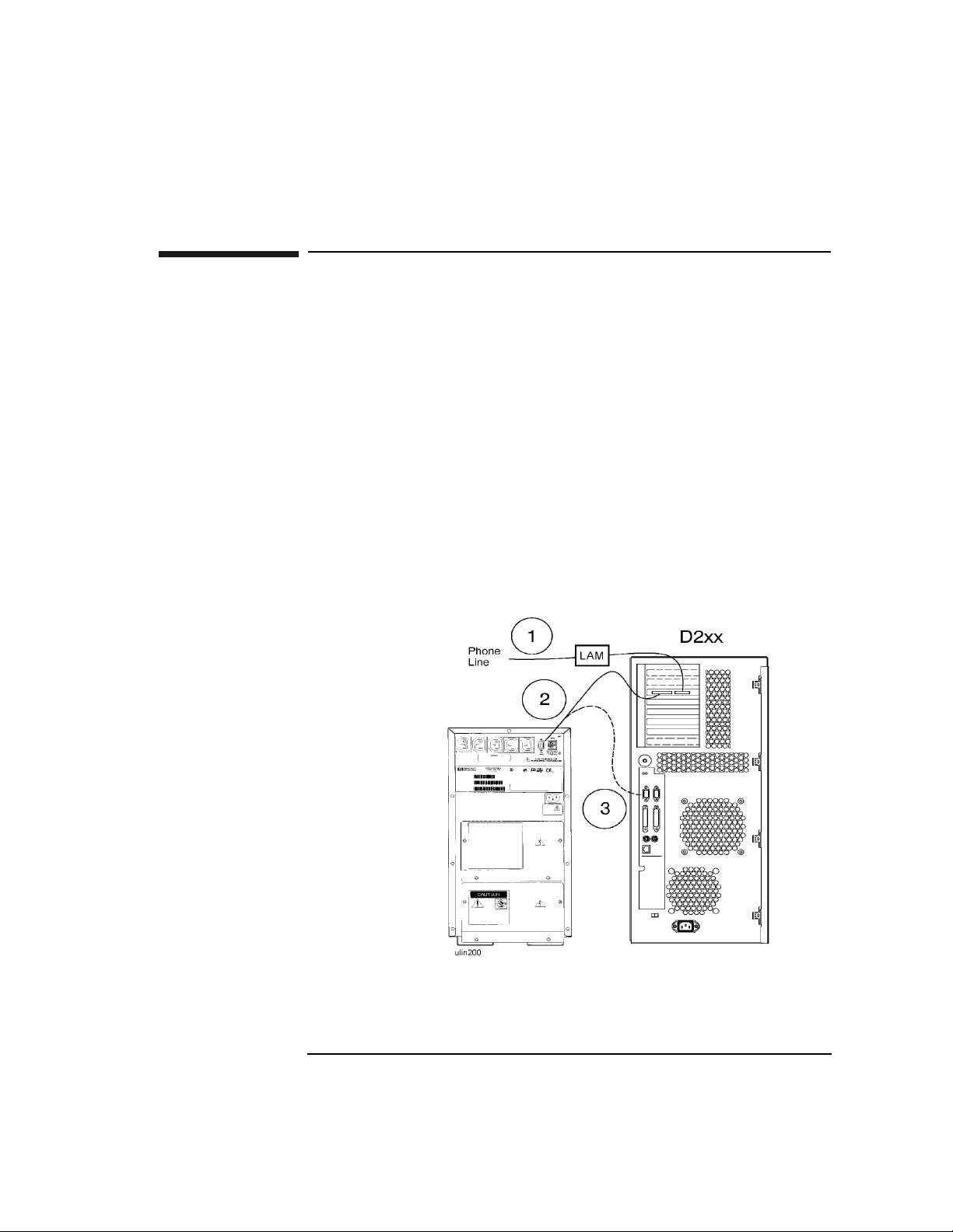
Model D2xx 1. If you have a Remote Management card, connect your Line Access Module
(LAM) for connecting to the phone line, to the Modem/LAM connector on the
Remote Management ca rd.
2. If you also have a UPS, connect the data ca ble from t he UPS Port on the UPS to
the UPS connector on the Remote Management card.
3. If you do not have a Remote Management card, connect the UPS data cable from
the UPS Port on the UPS to the connector on the server labeled Serial 2/UPS.
1-7
Page 14
D Class System Installation
4. Connect Remote Management Card and Serial Data Cable for the
Optional UPS
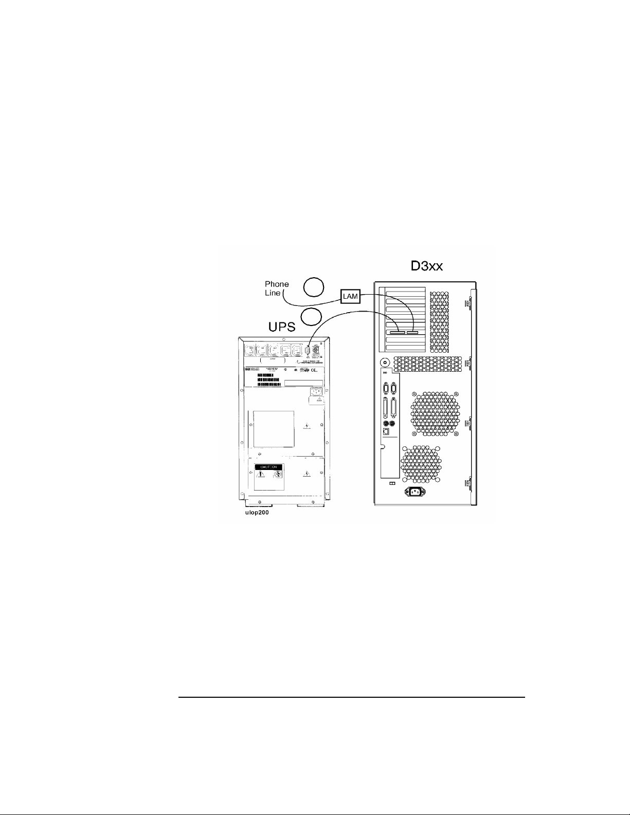
Model D3xx 1. Connect your Line Access Module (LAM), for connecting to the phone line, to
the Modem/LAM connector on the Remote Management (Access Por t ) card.
2. If you have a UPS, connect the UPS data cable from the UPS Port on the UPS
to the UPS connector on the Remote Management card.
1
2
1-8
Page 15

D Class System Installation
5. Set the Input Voltage Selector
5. Set the Input Voltage Selector
CAUTION To avoid damage to your server, be sure to set the input voltage s elector switch to a
setting wit hin the voltage range of the power source you intend to use. Always
check the switch setting before connecting the power cord.
1. If your input voltage is in the ra nge of 100 V to 127 V, set the voltage selector to
the 115 setting.
2. If your input voltage is in the ra nge of 200 V to 240 V, set the voltage selector to
the 230 setting.
NOTE System models Dx70, Dx80, and D390 have a power supply that automatically
switches to match the input vol tage level. There is no voltage sele ctor switch on
these models.
1-9
Page 16

D Class System Installation
6. Connect the System Power Cords
6. Connect the System Power Cords
How you connect the system power cords depe nds on whether your server
configuratio n includ es the opti onal Unin terrupt ibl e Power Syst em (UPS). Be sure to
connect power correctly for your system, as shown below.
WARNING Be sure the server cabinet is closed and secured before connecting power cord.
Refer to the WARNING on page 4.
The D Clas s servers can be connected to any UPS in the PowerTrust UPS fami ly,
except as noted below.
NOTE The A2941A PowerTrus t UPS (600VA) can only be used on the HP D200 and HP
D210 Deskside Enterprise Servers. All other D Class Enterprise Servers require an
A2994A PowerTrust UPS (1300VA), or larger. Contact your nearest HP Sales
Representative for more information.
The UPS shown in the following diagram is only representative. Contac t your
nearest HP Sales Representative for more inf o r mation.
1. If you do not have a UPS, connect both the D Clas s server and the console ( or
optional graphic s monitor) directly to your AC power source.
2. If you have a UPS, connec t the D Class server to the upper - left socket at the toprear of the UPS (using the cord supplied with the UPS), then connect the system
console (or optional graphics monitor) to one of the other AC Outle t s ockets
along the top of the UPS rear panel. Finally, connect your AC power source to
the input socket of the UPS.
1-10
Page 17

D Class System Installation
6. Connect the System Power Cords
1-11
Page 18

D Class System Installation
7. T urn On Power to the System
7. Turn On Power to the System
1. If you have the optio nal UPS, se t the Power s witch on the fr ont pane l of the UPS
to the ON position. The green AC Output light should be on. If any of the other
UPS front panel lights are on, refer to the UPS manual for appropriate action.
2. Turn on the system console (or graphics monitor).
3. Set the Power switch on the front panel of t he D Class server to the ON position.
The green lig ht inside the switch should c o me o n.
1-12
Page 19

D Class System Installation
8. Prepare for Network Connections
8. Prepare for Network Connections
To use your D Class s erver on a network, you will need the following information:
• LAN statio n address (see sy stem la bel )
• System name (or hostname)
• Internet Protocol (IP) address.
The LAN station addres s is provided on the server’s system label loca ted on the
inside of the front panel peripheral door. Write the number down and give it to your
system administra tor.
The hostname and IP address must be obtained from your system admini strator.
1-13
Page 20

D Class System Installation
9. Prepare for Termina l Connection s
9. Prepare for Termina l C o n n ection s
Configure your D Class server for terminal connections using the System
Administration Manager (SAM) program. To use SAM, refer to the following
man uals that were shipped with you r system:
• System Administration Tasks
• Configuring HP-UX for Peripherals.
For EISA MUX ca rd in stallat io n , re f er to th e m a nuals tha t came with th e E IS A
MUX card:
• HP EISA MUX Quick Installation Card
• HP EISA MUX Cabling, Diagnostics and Troubleshooting Guide.
Also ref er to the I/O C ar d In stallati o n gu id e that came with the system .
1-14
Page 21

D Class System Installation
10. Contacting Hewlett-Packard
10. Contacting Hew lett-Packard
If you need to contact Hewlett-Packard for assistance or addi tional information, you
may be asked for the syste m model number and serial numb er. That information is
located on the system label, on the back of the removable media ac cess door.
Reference Documents
Refer to the following documents for additional information on using your HP 9000
D Class server:
1. Installation gu id e that shipped with your console or graphics monitor -
Explains how to connect ca bles, operate, and place your console or monitor.
2. Operator’s Guide - Introduces your server’s features, and explains how to use
and maintain storage and input/output devices, and solve simpl e problems.
3. System Administration Tasks manual - Describes how to configure and
maintain your system softwa re.
4. Configuring HP-UX for Peripherals - Explains how to configure your server
to recognize add-on peri pherals.
5. I/O Card Upgrade Guide - Explains how to install ad d-on I/O cards.
6. Internal Peripheral Upgrade Guide - Explains how to install add-on internal
peripherals, such as disks, tape drives, and CD-ROM drives.
7. System Memory Upgrade Guide - Explains how to install add-on memory
modules.
8. System Upgrade Guide - Explains how to add additional processors, or replace
the existing processor with an upgraded processor.
9. System I/O Expansion Guide - Explains how to expand the I/O capabilit ies of
the D Class server.
10. HP EISA MUX Cabling, Diagnostics and Troubleshooting Guide - Explains
how to connect and troubl eshoot the EISA MUX card.
1-15
Page 22

D Class System Installation
10. Contacting Hewlett-Packard
1-16
Page 23

2 R Class Sy stem Installation
How to install the basic HP 9000 R Cla ss En terprise server and its associated
components, such as the cons ole and keyboard.
2-1
Page 24

R Class System Installation
Overview of System Installation
Overview of System Installation
Installation of a basic syste m consists of the following procedures:
1. If the server is not already integrated in a cabinet:
a. Install the rack kit into a cabinet
b. Mount the system on the cabinet rack
2. Install internal add-on options .
3. Connect the console, web console, or graphics monitor.
4. Connect the SCSI, network, and parallel cables.
5. Connect Remote Management (Access Port) card and the serial data cable for
the optional UPS.
6. Connect system power cords.
7. Turn on power to the system.
8. Prepare for network connec tions.
9. Prepare for te r minal conn e ct io n s .
2-2
Page 25

R Class System Installation
1. Install the Rack Kit and Server Into the Cabinet
1. Install the Rack Kit and Server Into the
Cabinet
If your R Class server ha s be en factory integ r ated into a cabinet, or if you are going
to oper at e th e R Cla ss ser v e r as a stand-al o ne un it , p r oc ee d to “2 . In st al l In t er n a l
Add-on Options ” on page 2-9. Otherwise, follow these instructions to install the
rack kit onto your cabinet and mount the server onto the rack in the cabinet.
WARNING The HP 9000 R Class Enterprise Serve r weighs about 38 kg (82 lbs). You must
use two people to lift the R Class server into the cabinet. R Class servers are
provided with a handle, located behind the removeable front bezel, to assist
with lifting.
Electrostatic
Discharge
Precautions
If you are installing additional cards or peripherals, you must ensure that they a re
not damaged due to electrostatic discharge (ESD). To prevent such damage from
occurring, observe the following ESD precautions when handling and installing
boards:
1. Use a grounding mat and an anti-static wris t st rap. These items are included in
the ESD Field Service Kit (HP P/N A3024-80004).
2. Wear the anti-static wrist strap to ensure that any accumulated electrostatic
charge is disc harged from your body to ground.
3. Keep uninstalled printed-circuit boa rds in their protective anti-static bags until
you are ready to instal l them.
4. Handle printed-circuit boa rds by their edges after you have removed them from
their protecti ve a nti-static bags.
2-3
Page 26

R Class System Installation
1. Install the Rack Kit and Server Into the Cabinet
1A. Install the Rack Kit
1. Decide where in the cabinet the new computer equipment is to be installed. R
Class servers should be installed in the cabinet’s topmost availa ble 6 EIA units On
C2785A, C2786A, and C2787A cabinets, each EIA unit is marked by a triangular
hole. On the J1501A, J1502A, and J1503A cabinets, these unit s are numbered.
2. Locate the rectangular mounting hol es on the ra ck co lumns for the support rail
(every fifth mounting hole is notc hed).
3. Position the four M5 sheet metal nuts over the top round holes adjacent to the
rectangular mounting holes.
4. If you have a n A4900A, A490 1A, or A4902A cabi net, insta ll one spac er into e ach
column, so the s heet metal nut is directly behi nd the top hole in the spa cer. See the
included spac er installation guide (J1516-90001) for detailed instructions.
5. Slip the ra il flanges i nto the rec tangul ar mount ing hole s of t he colu mn (or s pacer) .
The rails should st ay in place. The exampl e bel ow sh ows the rail flange ins erted in
the spacer.
2-4
Page 27

R Class System Installation
1. Install the Rack Kit and Server Into the Cabinet
6. Make sure the sheet metal nuts are aligned with the mounting holes in the rail.
7. Insert the M5x30mm mounting screws through the mounting holes on each rail,
(through the spacers, if used), into the sheet metal nuts, and tighten. See the figures
below for an example. The figure on the left shows installa tion without spacers.
8. Install th e new piece of computer equipment. Slide it all the way into the cabinet.
9. Slip the clam p into the rails from the rea r of the cabine t or rack (one fo r each rail ).
The raised edge of the cl ip s hould cover the rear edge of the computer equipment.
2-5
Page 28

R Class System Installation
1. Install the Rack Kit and Server Into the Cabinet
10. Install the retaining screws (one for each cl amp) into the mounting hol es using
the TORX screwdriver.
2-6
Page 29

R Class System Installation
1. Install the Rack Kit and Server Into the Cabinet
1B. Mount the System Into the Cabinet
Using two people, lift the s erver up and onto the r ails in the cabin et. Slide the server
toward the rear of the cab inet until the sheet metal extensions on the fa ce of the
server rest flush against the columns o f the cabinet. Secure the server to the cabinet
columns with four screws as shown:
2-7
Page 30

R Class System Installation
1. Install the Rack Kit and Server Into the Cabinet
Attach th e LCD and power switch bezel t o th e face o f t h e server, th en attach the
front panel bezel.
CAUTION Until t h e LCD and power switch bezel is attached , the area surroun d i n g the LC D is
ESD sensitive. S ee “E le ct r o static Dis ch a rge P r ec au ti o n s” on p ag e 2 - 3.
In the rear of the cabinet, adju st the rail slide against the rear of server.
2-8
Page 31

R Class System Installation
2. Insta ll In t e r nal Add -on Options
2. Install Internal Add-on Options
WARNING The HP 9000 R Class Enterprise Serve r weighs about 38 kg (82 lbs). You must
use two people to lift the R Class server cabinet.
1. Serial Connector
2. Serial 1/Console
R Class servers are configured at the facto ry to include most I /O cards and internal
peripherals.
If you have any internal ad d-on options, install them now according to th e
instructions shipped with the option.
REAR PANEL
CONNECTORS
3. Parallel
4. SCSI (Single -Ended)
LAN 10 Base-T
5.Graphics Keyboard
6. Graphics Mouse
7. LAN 10 Base-T
2-9
Page 32

R Class System Installation
2. Install Internal Add-on Options
WARNING DO NOT CONNECT SYSTEM POWER CORD AT THIS TIME. If you open
the system cabinet when power is connected, you will be exposed to high-energy
(high-amperage) circuits and possible ejection of molten metal. Be sure to
remove all rings, watches, and other je welry from fingers, wrists, and arms
before opening the system cabinet.
Electrostatic
Discharge
Precautions
If you are installing additional cards or peripherals, you must ensure that they a re
not damaged due to electrostatic discharge (ESD). To prevent such damage from
occurring, observe the following ESD precautions when handling and installing
boards:
1. Use a grounding mat and an anti-static wris t st rap. These items are included in
the ESD Field Service Kit (HP P/N A3024-80004).
2. Wear the anti-static wrist strap to ensure that any accumulated electrostatic
charge is disc harged from your body to ground.
3. Keep uninstalled printed-circuit boa rds in their protective anti-static bags until
you are ready to instal l them.
4. Handle printed-circuit boa rds by their edges after you have removed them from
their protecti ve a nti-static bags.
2-10
Page 33

R Class System Installation
3. Connect the Console, Web Console, or Graphics Monitor
3. Connect the Console, Web Console, or
Graphics Monitor
1. Console/
Keyboard
2. Web Consol e A Remote Web Console is shipped with each R Class Server and ca n be attached to
If you have an ASCII console (such as th e HP 700/96) connect it to the server rear
panel connector labeled Serial 1/ Console. Connect the keyboard to the keyboard
connector at the rear of the console.
the inside rear of the se rver using the two Velcro
To attach the Remote Web Console:
1. Separate the s trips to be attached to the web console from the strip already
attached to the side of the chassis.
strips located there.
2-11
Page 34

R Class System Installation
3. Connect the Console, Web Console, or Graphics Monitor
2. Remove the adhesive backing and attach the Velcro to the Remote Web Console
in the areas shown:
3. Align the Velcro strips on the Remote Web Console with the strips on the insi de
of the server chassis an d press toget her.
Connect the web cons ole to the RS-232 consol e port, using the cable (HP part
number A5176-63002) prov ided.
2-12
Page 35

R Class System Installation
3. Connect the Console, Web Console, or Graphics Monitor
IMPORTANT POWER ADAPTORS FOR THE REMOTE WEB CONSOLE:
The Remote Web Console, used with an R-Class server in either a racked or standalone con figuration, receives power from a sp ecial power adaptor included with
your shipment.
The locali zed power adaptor inc luded in the Remote Web Console box is qualified
for use ONLY for stand-alone (non-racke d) servers. Do not use this power adaptor
for rac ked server solutions.
Racked servers, whether pre-integrated at the factory or rack-mounted at the
customer site, must instead use the auto-ranging R Class W eb Console Power
Adaptor (HP Part No. 0950-3415) inc luded in the server accessories box. This
power adapto r can be secured to the rear of the server chassis using the Velcro strips
attached there (refer to the figure on page 2-10).
Do not discard the auto-ranging power adaptor even if the server is configured
as a stand-alon e unit. If the server is rack-mounted at a later date, the auto-ranging
power adaptor will be needed to provide the proper power supply to the Remote
Web Console.
Configure th e Remote Web Console using the instruc tions provid ed in its shipping
box.
2-13
Page 36

R Class System Installation
3. Connect the Console, Web Console, or Graphics Monitor
3. Graphics
Monitor,
Keyboard, Mouse
If you have a graphics monitor, connect it to the graphics I/O card at the rear of the
system cabinet . Connect the keyboard and mouse to the connectors labeled with
keyboard and mouse symbols at the rear of the cabinet.
The interface card for the graphics monitor can be instal led in any open HP-HSC
slot.
2-14
Page 37

R Class System Installation
4. Connect the SCSI, Network, and Parallel Cables
4. Connect the SCSI, Network, and Parallel
Cables
1. Connect your SCSI device cable to the connecto r labeled SCSI (Single-Ended)
on the server rear panel. If no SCSI cable is to be attached to the server, place or
leave the SCSI terminator (supplied with your serve r) on the SCSI (Single-
Ended) connector.
2. Connect your paral lel device, such as a printer, to the rear panel connector
labeled Parallel.
3. Read and remove the sticker that covers the connector, then connect your LAN
cable to the LAN 10 Base-T connector at the re ar of the R Class server.
NOTE An optional AUI adapter for the LAN 10 Base-T connector is av ailable (if special
ordered).
2-15
Page 38

R Class System Installation
5. Connect Remote Management Card and Serial Data Cable for the
Optional UPS
5. Connect Remote Management Card and Serial
Data Cable for the Optional UPS
R Class Servers The Remote Management card (also called the Access Port or AP card) is optional
on R Class servers. When present, the AP card is always installed in slot 0.
1. Connect your Line Access Module (LAM), for connecting to the phone line, to
the Modem/LAM connector on the Remote Management (Access Por t ) card.
2. If you have a UPS, connect the UPS data cable from the UPS Port on the UPS
to the UPS connector on the Remote Management card.
2-16
Page 39

R Class System Installation
6. Connect the System Power Cords
6. Connect the System Power Cords
How you connect the system power cords depe nds on whether your server
configuratio n includ es the opti onal Unin terrupt ibl e Power Syst em (UPS). Be sure to
connect power correctly for your system, as shown below.
WARNING Be sure the server cabinet is closed and secured before connecting power cord.
Refer to the WARNING on page 2-10.
NOTE All R Class Enterprise Servers require an A2994A Power Trust UPS (1300VA), or
larger. Contact your ne arest HP Sales Representative for more information.
The UPS shown in the following diagram is only representative. Contac t your
nearest HP Sales Representative for more inf o r mation.
1. If you do not have a UPS, connect both the R Clas s se rver and the console (or
web console, or optiona l graphics monitor) directly to your AC power sour ce .
2. If you have a UPS, connect the R Class server to the upper - left socket at the toprear of the UPS (using the cord supplied with the UPS), then connect the system
console, web c onsole, or op tio nal gra phi cs monit or to on e of the other AC Out let
2-17
Page 40

R Class System Installation
6. Connect the System Power Cords
sockets along the top of the UPS rear panel. Final ly, connect your AC power
source to the input socket of the UPS.
2-18
Page 41

R Class System Installation
7. Turn On Power to the System
7. Turn On Power to the System
1. If you have the optio nal UPS, se t the Power s witch on the fr ont pane l of the UPS
to the ON position. The green AC Output light should be on. If any of the other
UPS front panel lights are on, refer to the UPS manual for appropriate action.
2. Turn on the system console or graphics monitor.
3. Set the Power switch on t he front panel of th e R Clas s server to the ON positi on.
The green lig ht inside the switch should c o me o n.
2-19
Page 42

R Class System Installation
8. Prepare for Network Connections
8. Prepare for Network Connections
To use your R Class server on a network, you will need the following information:
• LAN statio n address (see sy stem la bel )
• System name (or hostname)
• Internet Protocol (IP) address.
The LAN station addres s is provided on the server’s system label located on the
inside of the front panel peripheral door. Write the number down and give it to your
system administra tor.
The hostname and IP address must be obtained from your system admini strator.
2-20
Page 43

R Class System Installation
9. Prepare for Terminal Con nection s
9. Prepare for Termina l C o n n ection s
Configure your R Class server for terminal connections using the System
Administration Manager (SAM) program. To use SAM, refer to the following
man uals that were shipped with you r system:
• System Administration Tasks
• Configuring HP-UX for Peripherals.
For EIS A MU X card inst al la tion, ref er to th e m a nuals tha t came with th e E IS A
MUX card:
• HP EISA MUX Quick Installation Card
• HP EISA MUX Cabling, Diagnostics and Troubleshooting Guide.
Also ref er to the I/O C ar d In stallati o n gu id e that came with the system .
2-21
Page 44

R Class System Installation
Contacting Hewlett-Packard
Contacting Hewlett-Packard
If you need to contact Hewlett-Packard for assistance or addi tional information, you
may be asked for the system model number and serial number. That information is
located on the system label, on the back of the removable media ac cess door.
Reference Documents
Refer to the following documents for additional information on using your HP 9000
R Class server:
1. Installation gu id e that shipped with your console or graphics monitor -
Explains how to connect ca bles, operate, and place your console or monitor.
2. Operator’s Guide - Introduces your server’s features, and explains how to use
and maintain storage and input/output devices, and solve simpl e problems.
3. System Administration Tasks manual - Describes how to configure and
maintain your system softwa re.
4. Configuring HP-UX for Peripherals - Explains how to configure your server
to recognize add-on peri pherals.
5. I/O Card Upgrade Guide - Explains how to install ad d-on I/O cards.
6. Internal Peripheral Upgrade Guide - E xplains how to instal l add-on internal
peripherals, such as disks, tape drives, and CD-ROM drives.
7. System Memory Upgrade Guide - Explains how to install add-on memory
modules.
8. System Upgrade Guide - Explains how to add additional processors, or replace
the existing processor with an upgraded processor.
9. System I/O Expansion Guide - Explains how to expand the I/O capabilit ies of
the R Cla s s s erv er.
10. HP EISA MUX Cabling, Diagnos tics and Troubleshooting Guide - Explains
how to connect and troubl eshoot the EISA MUX card.
2-22
 Loading...