

Page 1

Maintenance & Service Guide
HP EliteOne 800 G2 23 inch All-in-One
HP EliteOne 705 G2 23-inch Touch All-in-One
HP ProOne 600 G2 21 inch All-in-One
Page 2

© Copyright 2015 HP Development Company,
L.P.
AMD is a trademark of Advanced Micro Devices,
Inc. Bluetooth is a trademark owned by its
proprietor and used by HP Inc. under license.
Intel, Celeron, and Pentium are trademarks of
Intel Corporation in the U.S. and other
countries. Microsoft and Windows are
trademarks of the Microsoft group of
companies.
The information contained herein is subject to
change without notice. The only warranties for
HP products and services are set forth in the
express warranty statements accompanying
such products and services. Nothing herein
should be construed as constituting an
additional warranty. HP shall not be liable for
technical or editorial errors or omissions
contained herein.
First Edition: September 2015
Document Part Number: 822875-001
Product notice
This user guide describes features that are
common to most models. Some features may
not be available on your computer.
Not all features are available in all editions of
Windows. This computer may require upgraded
and/or separately purchased hardware, drivers
and/or software to take full advantage of
Windows functionality. Go to
http://www.microsoft.com for details.
Software terms
By installing, copying, downloading, or
otherwise using any software product
preinstalled on this computer, you agree to be
bound by the terms of the HP End User License
Agreement (EULA). If you do not accept these
license terms, your sole remedy is to return the
entire unused product (hardware and software)
within 14 days for a full refund subject to the
refund policy of your seller.
For any further information or to request a full
refund of the price of the computer, please
contact your seller.
Page 3

About This Book
WARNING! Text set o in this manner indicates that failure to follow directions could result in bodily harm or
loss of life.
CAUTION: Text set o in this manner indicates that failure to follow directions could result in damage to
equipment or loss of information.
NOTE: Text set o in this manner provides important supplemental information.
iii
Page 4

iv About This Book
Page 5

Table of contents
1 Product features ........................................................................................................................................... 1
Overview ................................................................................................................................................................ 1
EliteOne 800 ........................................................................................................................................................... 2
Front components ............................................................................................................................... 2
Side components ................................................................................................................................. 3
Rear components ................................................................................................................................ 4
Internal components ........................................................................................................................... 5
EliteOne 705 ........................................................................................................................................................... 6
Front components ............................................................................................................................... 6
Side components ................................................................................................................................. 7
Rear components ................................................................................................................................ 8
Internal components ........................................................................................................................... 9
ProOne 600 .......................................................................................................................................................... 10
Front components ............................................................................................................................. 10
Side components ............................................................................................................................... 11
Rear components .............................................................................................................................. 12
Internal components ......................................................................................................................... 13
Labels ................................................................................................................................................................... 14
2 Illustrated parts catalog .............................................................................................................................. 15
System parts ........................................................................................................................................................ 15
Misc parts ............................................................................................................................................................. 17
Mass storage devices ........................................................................................................................................... 19
Processors and memory modules ....................................................................................................................... 20
Cables ................................................................................................................................................................... 21
Keyboards and mice ............................................................................................................................................. 21
3 Routine care, SATA drive guidelines, and disassembly preparation .................................................................. 23
Electrostatic discharge information .................................................................................................................... 23
Generating static ............................................................................................................................... 24
Preventing electrostatic damage to equipment ............................................................................... 24
Personal grounding methods and equipment .................................................................................. 25
Grounding the work area ................................................................................................................... 25
Recommended materials and equipment ........................................................................................ 25
Operating guidelines ........................................................................................................................................... 26
Routine care ......................................................................................................................................................... 26
v
Page 6

General cleaning safety precautions ................................................................................................ 26
Cleaning the Computer Case ............................................................................................................. 27
Cleaning the keyboard ....................................................................................................................... 27
Cleaning the monitor ......................................................................................................................... 27
Cleaning the mouse ........................................................................................................................... 28
Service considerations ......................................................................................................................................... 28
Tools and software Requirements .................................................................................................... 28
Screws ............................................................................................................................................... 28
Cables and connectors ...................................................................................................................... 28
Hard Drives ........................................................................................................................................ 28
Lithium coin cell battery .................................................................................................................... 29
SATA hard drive cables ......................................................................................................................................... 30
SATA data cable ................................................................................................................................. 30
Cable management .............................................................................................................................................. 30
4 Removal and Replacement Procedures .......................................................................................................... 31
Preparing to disassemble the computer ............................................................................................................. 31
Rear port cover .................................................................................................................................................... 31
Attaching and removing a stand ......................................................................................................................... 32
Recline stand ..................................................................................................................................... 32
Attaching a recline stand ................................................................................................ 32
Removing a recline stand ............................................................................................... 33
Adjustable-height stand ................................................................................................................... 34
Attaching an adjustable-height stand ............................................................................ 34
Removing an adjustable-height stand ........................................................................... 34
Easel stand ........................................................................................................................................ 35
Attaching an easel stand ................................................................................................ 35
Removing an easel stand ................................................................................................ 35
Access panel ......................................................................................................................................................... 37
Drives ................................................................................................................................................................... 38
Hard disc drive ................................................................................................................................... 39
Removing a 2.5-inch hard disc drive .............................................................................. 39
Installing a 2.5-inch hard disc drive ................................................................................ 40
Optical drive ....................................................................................................................................... 41
Converter board ................................................................................................................................................... 43
Top trim ................................................................................................................................................................ 45
Webcam module .................................................................................................................................................. 46
System board (EMI) shield ................................................................................................................................... 48
Memory ................................................................................................................................................................ 49
Battery ................................................................................................................................................................. 52
PCI-Express M.2 Solid-State Drive ....................................................................................................................... 54
vi
Page 7

WLAN module ...................................................................................................................................................... 56
Antennas .............................................................................................................................................................. 58
Heat sink .............................................................................................................................................................. 59
Processor – AMD models ..................................................................................................................................... 61
Processor – Intel models ..................................................................................................................................... 62
System board ....................................................................................................................................................... 64
System board callouts ......................................................................................................................................... 67
System board callouts, HP EliteOne 705 G2 models ........................................................................ 67
System board callouts, HP EliteOne 800 G2 dGPU models .............................................................. 68
System board callouts, HP EliteOne 800 G2 UMA models ................................................................ 69
System board callouts, HP ProOne 600 G2 models .......................................................................... 70
Serial/PS2 board .................................................................................................................................................. 71
Center rear I/O panel ............................................................................................................................................ 73
Speakers .............................................................................................................................................................. 74
VESA mounting bracket ....................................................................................................................................... 75
Power supply ....................................................................................................................................................... 77
Fan assembly ....................................................................................................................................................... 79
Right trim and ngerprint reader ........................................................................................................................ 80
Left trim ............................................................................................................................................................... 82
Bottom trim and feet ........................................................................................................................................... 83
Display panel ....................................................................................................................................................... 85
Cables and connectors ......................................................................................................................................... 88
5 Computer Setup (F10) Utility ........................................................................................................................ 89
Computer Setup (F10) Utilities ............................................................................................................................ 89
Using Computer Setup (F10) Utilities ................................................................................................ 89
Computer Setup–Main ....................................................................................................................... 91
Computer Setup—Security ............................................................................................................... 93
Computer Setup—Advanced ............................................................................................................. 95
Recovering the Conguration Settings ............................................................................................................. 100
6 Using HP PC Hardware Diagnostics (UEFI) ..................................................................................................... 101
Downloading HP PC Hardware Diagnostics (UEFI) to a USB device .................................................................. 101
7 Troubleshooting without diagnostics .......................................................................................................... 103
Safety and comfort ............................................................................................................................................ 103
Before you call for technical support ................................................................................................................ 103
Helpful hints ...................................................................................................................................................... 104
Solving general problems .................................................................................................................................. 105
Solving power problems .................................................................................................................................... 109
vii
Page 8

Solving hard drive problems .............................................................................................................................. 110
Solving media card reader problems ................................................................................................................ 112
Solving display problems .................................................................................................................................. 113
Solving audio problems ..................................................................................................................................... 118
Solving printer problems ................................................................................................................................... 120
Solving keyboard and mouse problems ............................................................................................................ 121
Solving Hardware Installation Problems ........................................................................................................... 123
Solving Network Problems ................................................................................................................................ 124
Solving memory problems ................................................................................................................................ 127
Solving CD-ROM and DVD problems .................................................................................................................. 128
Solving USB ash drive problems ..................................................................................................................... 131
Solving front panel component problems ........................................................................................................ 132
Solving Internet access problems ..................................................................................................................... 132
Solving software problems ............................................................................................................................... 134
8 System backup and recovery ...................................................................................................................... 135
Backing up, restoring, and recovering in Windows 10 ...................................................................................... 135
Creating recovery media and backups ............................................................................................ 135
Creating HP Recovery media (select products only) .................................................... 135
Using Windows tools ....................................................................................................................... 136
Restore and recovery ...................................................................................................................... 136
Recovering using HP Recovery Manager ...................................................................... 137
What you need to know before you get started ........................................ 137
Using the HP Recovery partition (select products only) ............................ 138
Using HP Recovery media to recover ......................................................... 138
Changing the computer boot order ............................................................ 138
Removing the HP Recovery partition (select products only) ..................... 138
Backing up, restoring, and recovering in Windows 8.1 or Windows 8 .............................................................. 139
Creating recovery media and backups ............................................................................................ 139
Restoring and recovering using Windows tools ............................................................................. 140
Using Reset when the system is not responding ......................................................... 140
Recovery using the Windows recovery USB ash drive ............................................... 140
Recovery using Windows operating system media (purchased separately) ............... 141
Backing up, restoring, and recovering in Windows 7 ........................................................................................ 141
Creating recovery media ................................................................................................................. 142
Creating recovery media using HP Recovery Manager (select models only) ............... 142
Creating recovery discs with HP Recovery Disc Creator (select models only) ............. 143
Creating recovery discs .............................................................................. 143
Backing up your information ........................................................................................ 144
System Restore ............................................................................................................................... 144
System Recovery ............................................................................................................................. 145
viii
Page 9

System Recovery when Windows is responding .......................................................... 145
System Recovery when Windows is not responding .................................................... 146
System Recovery using recovery media (select models only) ..................................... 146
Using HP Recovery Disc operating system discs (select models only) ........................ 147
9 POST error messages and diagnostic front panel LEDs and audible codes ....................................................... 149
POST numeric codes and text messages .......................................................................................................... 149
Interpreting system validation diagnostic front panel LEDs and audible codes .............................................. 154
10 Password security and resetting CMOS ...................................................................................................... 156
Resetting the password jumper ........................................................................................................................ 156
Clearing and resetting the BIOS ........................................................................................................................ 158
Appendix A Power cord set requirements ....................................................................................................... 159
General requirements ........................................................................................................................................ 159
Japanese power cord requirements .................................................................................................................. 159
Country-specic requirements .......................................................................................................................... 160
Appendix B Statement of Volatility ................................................................................................................ 161
Appendix C Specications ............................................................................................................................. 162
HP EliteBook 800 G2 models ............................................................................................................................. 162
HP EliteBook 705 G2 models ............................................................................................................................. 163
HP ProBook 600 G2 models .............................................................................................................................. 164
Index ........................................................................................................................................................... 165
ix
Page 10

x
Page 11
1 Product features
Overview
NOTE: For the latest specications or additional specications on this product, go to
http://www.hp.com/go/ quickspecs/ and search for your specic display model to nd the model-specic
QuickSpecs.
CAUTION: Several well-known vulnerabilities exist when a computer is in the Sleep state. To prevent an
unauthorized user from accessing data on your computer, even encrypted data, HP recommends that you
always initiate Hibernation instead of Sleep anytime the computer will be out of your physical
possession. This practice is particularly important when you travel with your computer.
Overview 1
Page 12

EliteOne 800
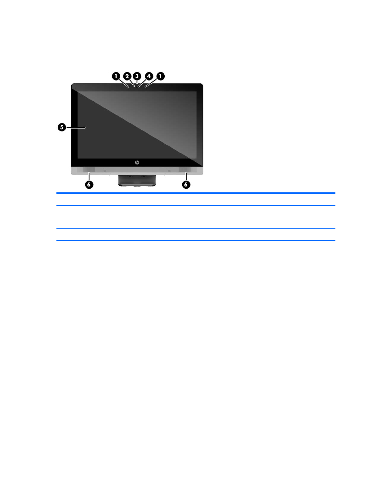
Front components
Component Component
1 Dual microphone array (optional) 4 Webcam (optional)
2 Webcam activity LED (with optional webcam) 5 16:9 widescreen LED-backlit LCD display
3 Webcam privacy shutter slide switch 6 High-performance stereo speakers
2 Chapter 1 Product features
Page 13
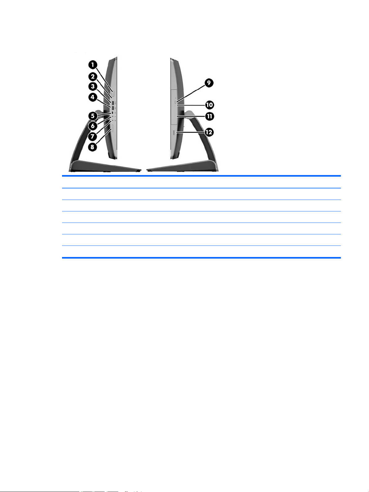
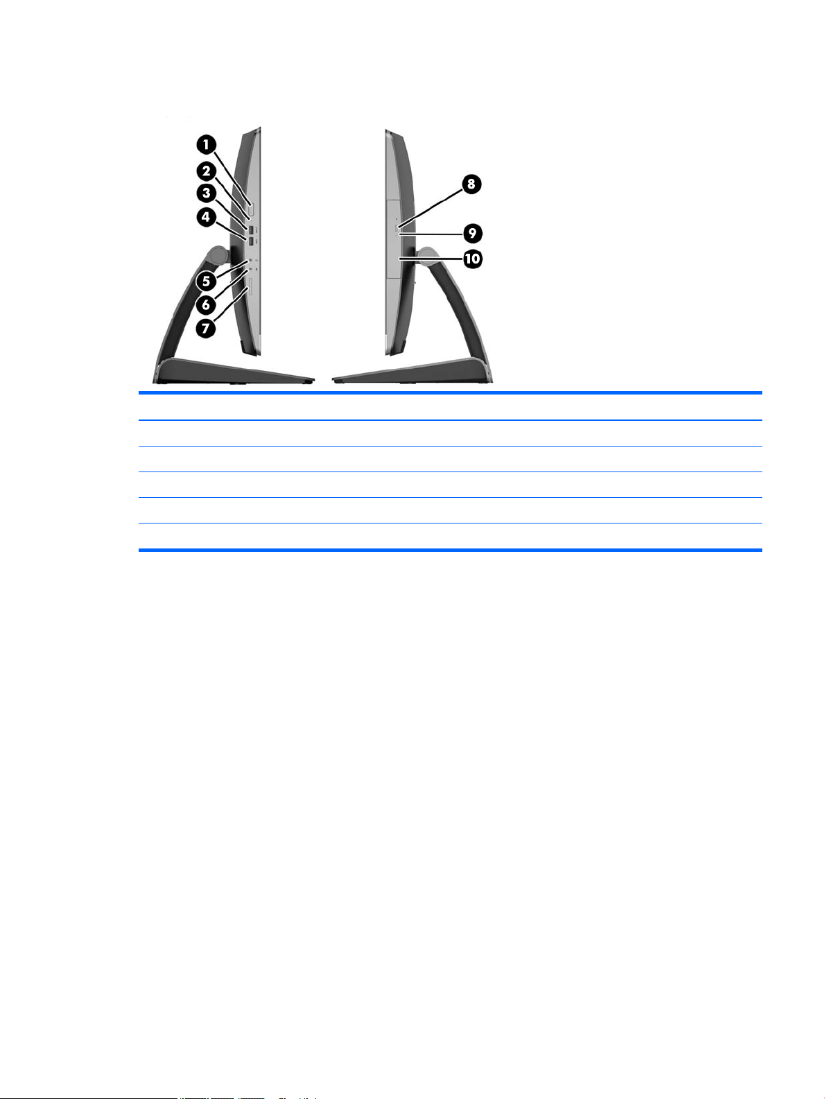
Side components
Component Component
1 Power button 7 Microphone/line in jack
2 hard disk drive activity LED 8 HP SD media card reader (optional)
3 USB 3.0 port, fast-charging 9 Optical disc drive eject button
4 USB 3.0 port 10 Optical disc drive activity LED
5 USB 3.0 Type C port 11 Tray-load optical disc drive
6 Headset/line out jack 12 Fingerprint reader (Touch model only)
EliteOne 800 3
Page 14

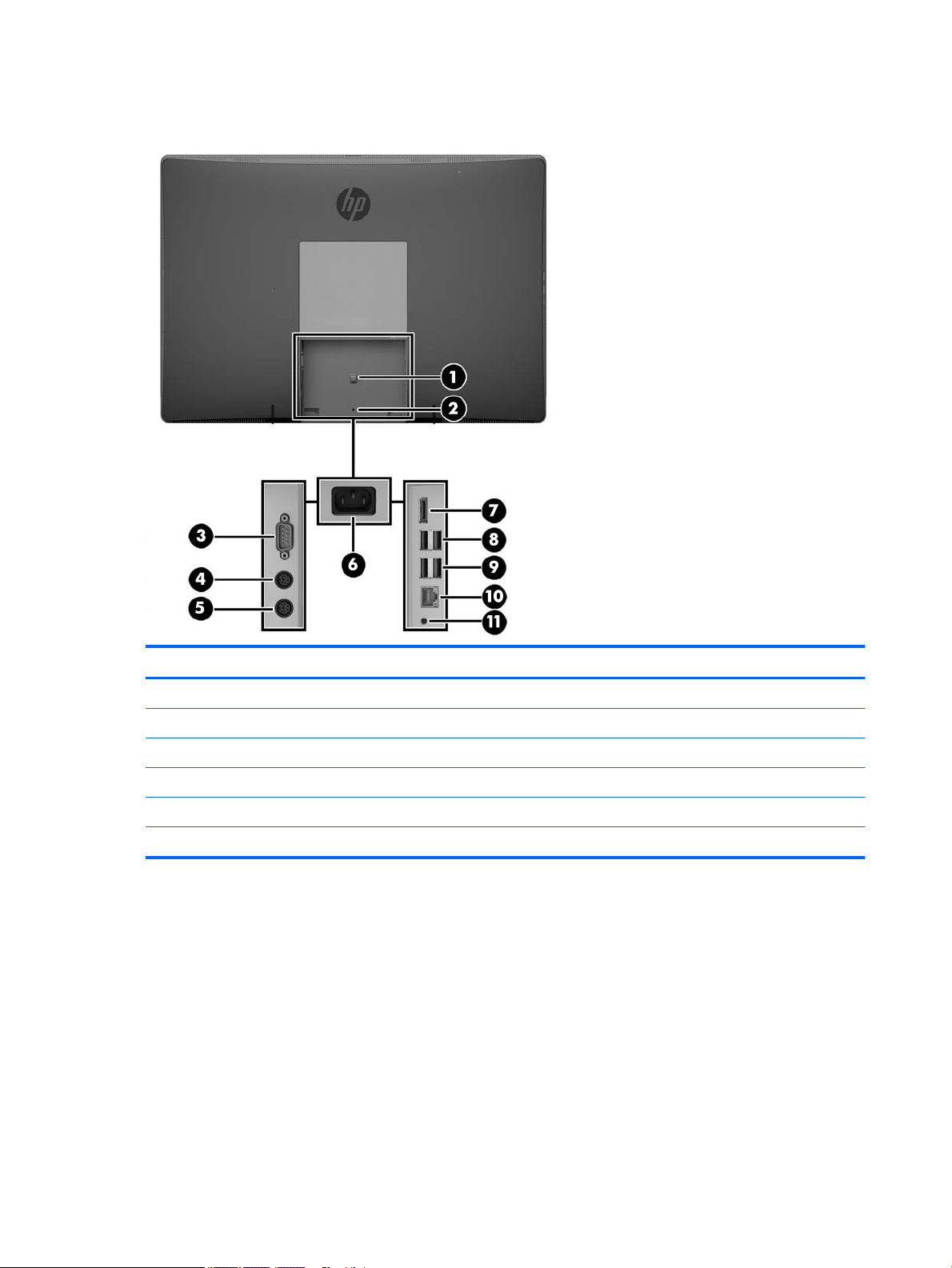
Rear components
Component Component
1 Power cable retention loop 7 DisplayPort connector
2 Port cover security screw hole 8 (2) USB 3.0 ports
3 Serial port (optional) 9 (2) USB 3.0 ports with wake-up functionality
4 PS/2 keyboard connector (optional) 10 RJ-45 Gigabit Ethernet port
5 PS/2 mouse connector (optional) 11 Stereo audio line out
6 Power connector
4 Chapter 1 Product features
Page 15

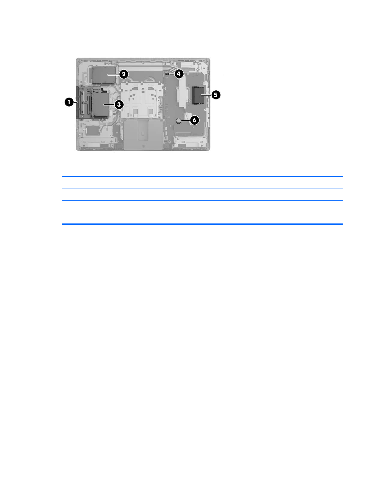
Internal components
Component Component
1 Optical disc drive 4 Hood sensor
2 Secondary hard disk drive 5 Memory
3 Primary hard disk drive 6 RTC Battery
EliteOne 800 5
Page 16
EliteOne 705
Front components
Component Component
1 Dual microphone array (optional) 4 Webcam (optional)
2 Webcam activity LED (with optional webcam) 5 16:9 widescreen LED-backlit LCD display
3 Webcam privacy shutter slide switch 6 High-performance stereo speakers
6 Chapter 1 Product features
Page 17

Side components
Component Component
1 Power button 7 HP SD media card reader (optional)
2 hard disk drive activity LED 8 Optical disc drive eject button
3 USB 3.0 port, fast-charging 9 Optical disc drive activity LED
4 USB 3.0 port 10 Tray-load optical disc drive
5 Headset/line out jack 11 Fingerprint reader (Touch model only)
6 Microphone/line in jack
EliteOne 705 7
Page 18
Rear components
Component Component
1 Power cable retention loop 7 DisplayPort connector
2 Port cover security screw hole 8 (2) USB 3.0 ports
3 Serial port (optional) 9 (2) USB 2.0 ports with wake-up functionality
4 PS/2 keyboard connector (optional) 10 RJ-45 Gigabit Ethernet port
5 PS/2 mouse connector (optional) 11 Stereo audio line out
6 Power connector
8 Chapter 1 Product features
Page 19
Internal components
Component Component
1 Optical disc drive 4 Hood sensor
2 Secondary hard disk drive 5 Memory
3 Primary hard disk drive 6 RTC Battery
EliteOne 705 9
Page 20

ProOne 600
Front components
Component Component
1 Dual microphone array (optional) 4 Webcam (optional)
2 Webcam activity LED (with optional webcam) 5 16:9 widescreen LED-backlit LCD display
3 Webcam privacy shutter slide switch 6 High-performance stereo speakers
10 Chapter 1 Product features
Page 21
Side components
Component Component
1 Power button 6 Microphone/line in jack
2 hard disk drive activity LED 7 HP SD media card reader (optional)
3 USB 3.0 port, fast-charging 8 Optical disc drive eject button
4 USB 3.0 port 9 Optical disc drive activity LED
5 Headset/line out jack 10 Tray-load optical disc drive
ProOne 600 11
Page 22

Rear components
Component Component
1 Power cable retention loop 7 DisplayPort connector
2 Port cover security screw hole 8 (2) USB 3.0 ports
3 Serial port (optional) 9 (2) USB 3.0 ports with wake-up functionality
4 PS/2 keyboard connector (optional) 10 RJ-45 Gigabit Ethernet port
5 PS/2 mouse connector (optional) 11 Stereo audio line out
6 Power connector
12 Chapter 1 Product features
Page 23
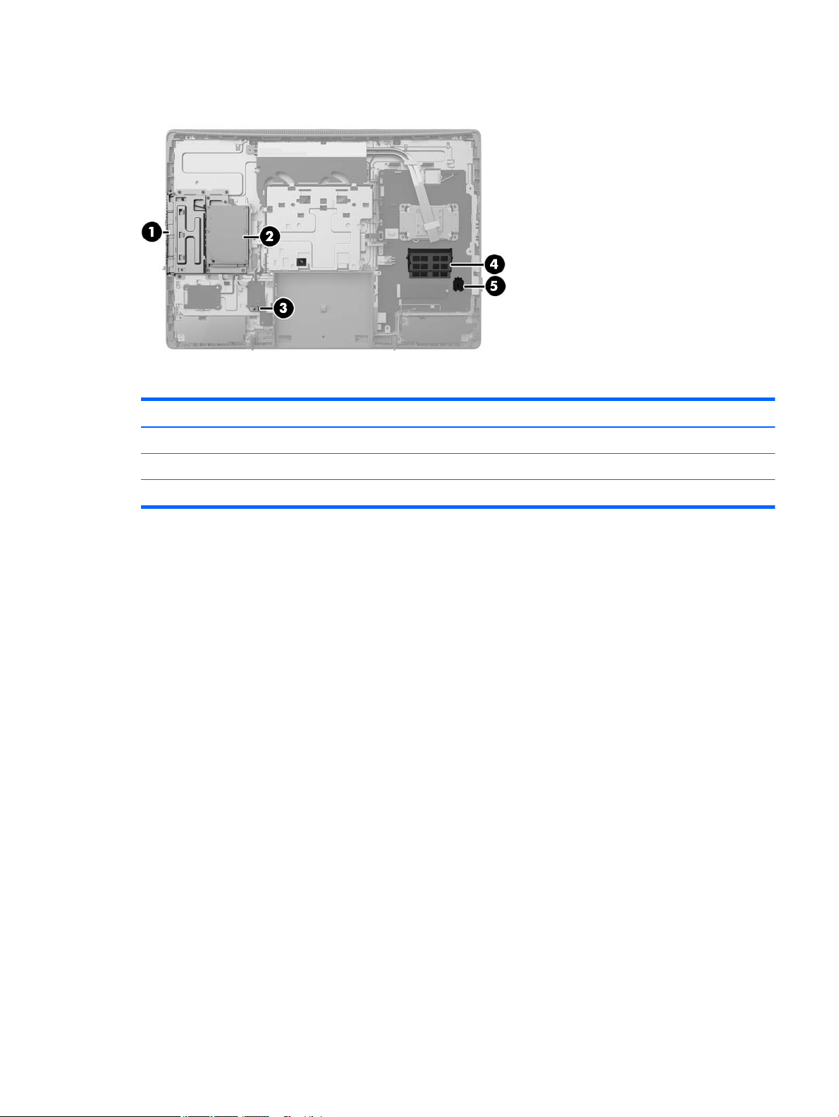
Internal components
Component Component
1 Optical disc drive 4 Memory
2 hard disk drive 5 RTC Battery
3 Hood sensor
ProOne 600 13
Page 24
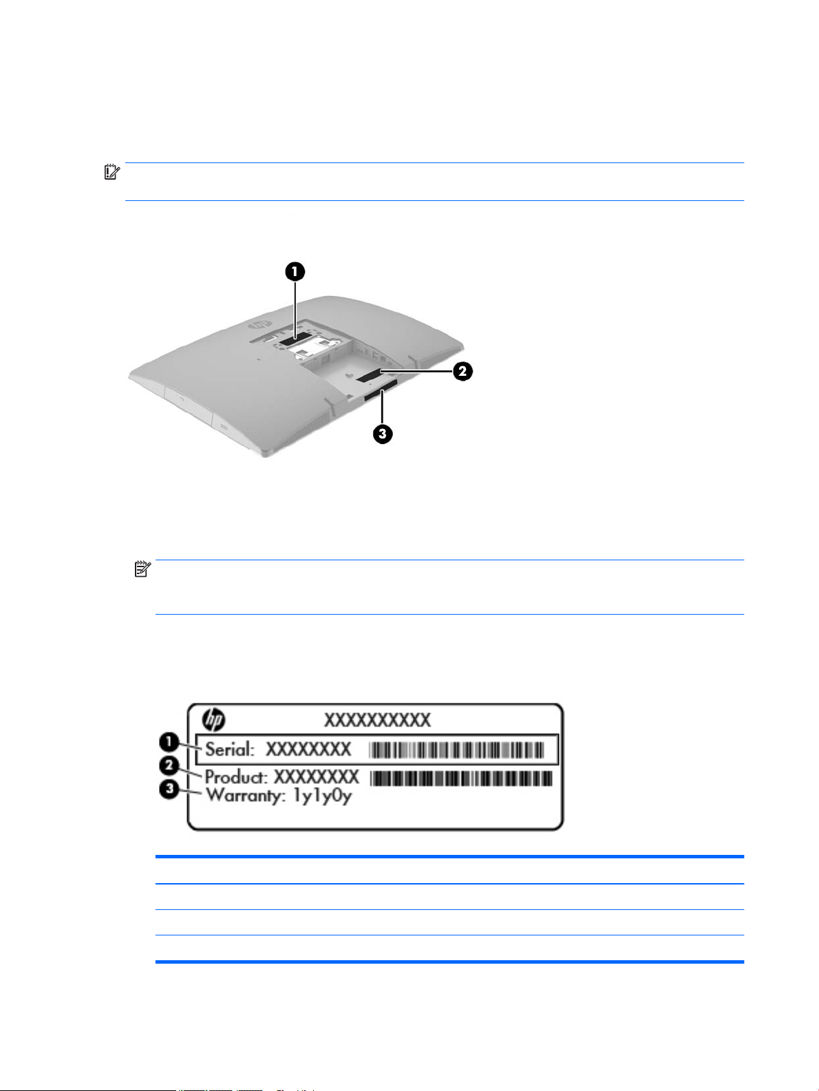
Labels
The labels axed to the computer provide information you may need when you troubleshoot system
problems or travel internationally with the computer.
IMPORTANT: All labels described in this section will be located under the stand or axed to the bottom of
the computer.
1. Microsoft® Certicate of Authenticity label (select models only prior to Windows 8)—Contains the
Windows Product Key. You may need the Product Key to update or troubleshoot the operating system.
HP platforms preinstalled with Windows 8 or Windows 8.1 do not have the physical label, but have a
Digital Product Key electronically installed.
NOTE: This Digital Product Key is automatically recognized and activated by Microsoft Operating
Systems on a reinstall of the Windows 8 or Windows 8.1 operating system with HP-approved recovery
methods.
2. Service label—Provides important information to identify your computer. When contacting support, you
will probably be asked for the serial number, and possibly for the product number or the model number.
Locate these numbers before you contact support.
Component
(1) Serial number
(2) Product number
(3) Warranty period
3. Serial number label
14 Chapter 1 Product features
Page 25
2 Illustrated parts catalog
Component appearance may vary depending on model.
NOTE: HP continually improves and changes product parts. For complete and current information on
supported parts for your computer, go to http://partsurfer.hp.com, select your country or region, and then
follow the on-screen instructions.
System parts
System parts 15
Page 26

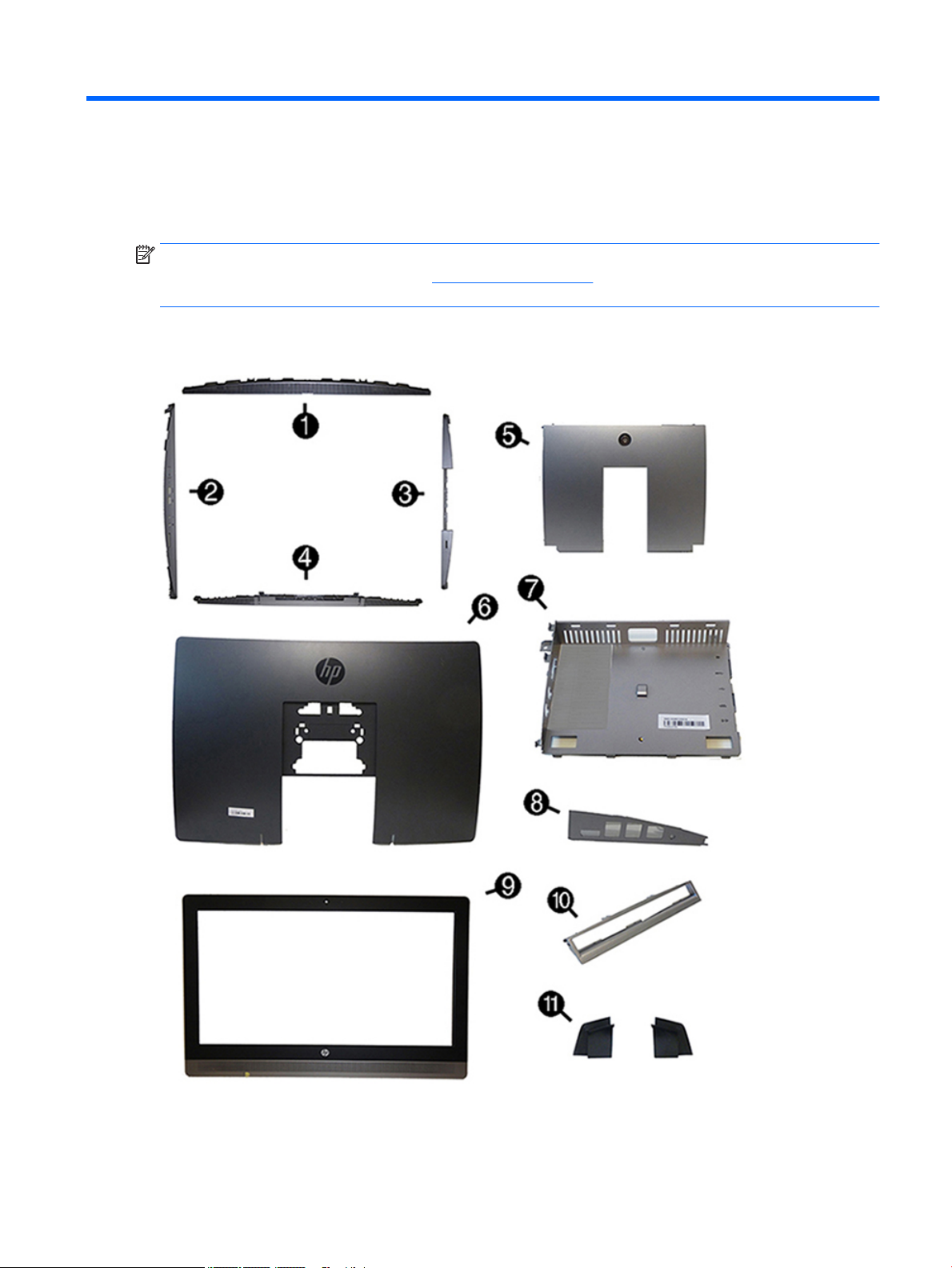
Item Description
Panel/trim kit, includes
(1) Left side trim
(2) Right side trim (includes ngerprint reader and cable)
(3) Top trim
(4) Bottom trim
(5) Rear port cover
(6) Rear cover (main)
(7) Center rear I/O panel with mylar
(8) Rear I/O port cover
(9) Front bezel (for use in non-touch models)
(10) Optical drive bezel trim (only for use in models with an expansion option in the optical drive bay)
(11) Rubber feet (right and left)
* Optical drive bezel blank (for use in models without an optical drive; not illustrated)
* Stands (not illustrated)
Adjustment Height Stand
Easel Stand
Recline Stand
* VESA cover (for use in models with out a stand)
* Display (touch screen; not illustrated)
* Display Kit (non-touch; not illustrated)
16 Chapter 2 Illustrated parts catalog
Page 27
Misc parts
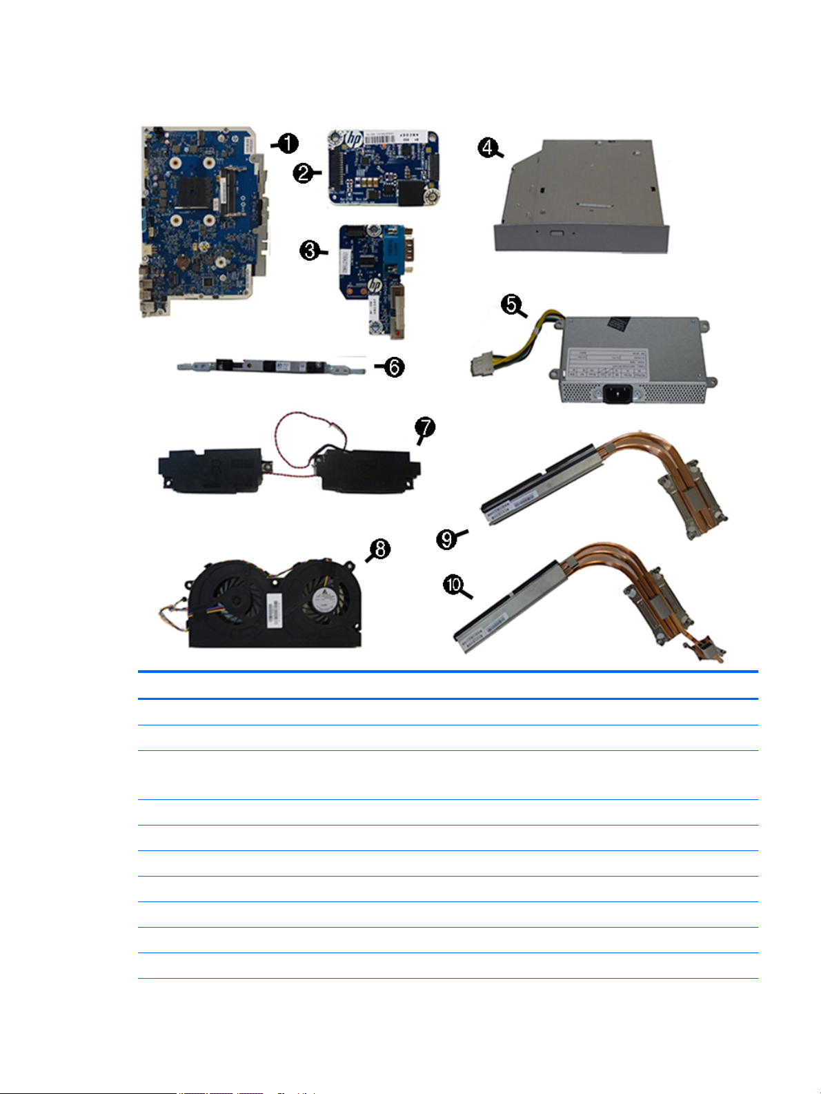
Item Description
(1) System board
(2) Converter board
(3) Serial port and PS/2 connector board
NOTE: HP ProOne 600 models also include a hood sensor on the serial port / PS2 board.
(4) Optical drive (includes latch)
Blu-ray writer (BD-RE) drive
DVD±RW drive
DVD-ROM drive
(5) Power supply
200W (for use in models with UMA graphics)
160W (for use in models with discrete graphics)
Misc parts 17
Page 28

Item Description
(6) Webcam module
(7) Speakers (left and right)
(8) Fan
Heat sink (thermal module) (includes replacement thermal material)
(9) For use in models with UMA graphics
(10) For use in models with discrete graphics
* WLAN modules
Intel Dual Band Wireless-AC 7265 NV (for use in HP EliteBook 800/705 models and HP ProBook 600 models)
HP WLAN 802.11 a/b/g/n + Bluetooth 4.0 (for use in HP EliteBook 800/705 models and HP ProBook 600 models)
Intel Dual Band Wireless-AC 8260 + Bluetooth 4.0 (for use in HP EliteBook 800 models)
Intel Dual Band Wireless-AC 3165 + Bluetooth 4.0 (for use in HP EliteBook 800 models)
* Mylar cover (for use in models without speakers)
* Card reader cover
* Hard drive isolation grommets
* Charger stand (for use in HP ProBook 600 models)
* Hood sensor (for use in HP ProBook 600 models only)
* Webcam shutter blank (for use in models without a webcam)
* Secure Digital card reader blank (for use in models without an SD card reader)
* HP Executive Capacitive Stylus
* HP ultraslim keyed cable lock (not illustrated)
18 Chapter 2 Illustrated parts catalog
Page 29

Mass storage devices
Description
Optical drive (does not include bezel)
Blu-ray writer (BD-RE) drive
DVD±RW drive
DVD-ROM drive
Primary hard drive (not illustrated)
1 TB, hybrid SSD drive
1 TB, 7200 rpm
500 GB, hybrid SSD drive
500 GB, 7200 rpm hard drive, self-encrypting (SED)
500 GB, 7200 rpm hard drive
500 GB, 5400 rpm hard drive, FIPS
500 GB, 5400 rpm hard drive, 5 mm
320 GB, 7200 rpm hard drive
Primary solid-state drive (not illustrated)
1-TB solid-state drive, OPAL 2.0, self-encrypting (SED)(ProOne 600 models)
512-GB solid-state drive, TLC
512-GB solid-state drive, 3D, NAND (EliteOne 800 and ProOne 600 models)
512-TB solid-state drive, OPAL 2.0, self-encrypting (SED)(ProOne 600 models)
256-GB solid-state drive, OPAL 2.0, self-encrypting (SED)
256-GB solid-state drive
256-GB solid-state drive, TLC
256-GB solid-state drive, 3D, NAND (EliteOne 800 and ProOne 600 models)
180-GB solid-state drive
180-GB solid-state drive, OPAL 2.0, MLC
128-GB solid-state drive, OPAL 2.0, self-encrypting (SED)
128-GB solid-state drive, TLC
128-GB solid-state drive
128-GB solid-state drive, 3D, NAND (EliteOne 800 and ProOne 600 models)
120-GB solid-state drive
120-GB solid-state drive, OPAL 2.0, MLC
Secondary hard drive (not illustrated)
1 TB, hybrid SSD drive
500 GB, hybrid SSD drive
Mass storage devices 19
Page 30

Description
Internal PCIe storage
256-GB solid-state drive, 2280SS, PCIe, NVMe
128-GB solid-state drive, 2280SS, PCIe, NVMe
Processors and memory modules
Description
Memory modules (SODIMM; PC4-17000, 1.2 V; not illustrated; for use in EliteOne 800 and ProOne 600 models)
16-GB
8-GB
4-GB
Memory modules (SODIMM; PC3-12800, 1.5 V; not illustrated; for use in EliteOne 705 models)
8-GB
4-GB
AMD Processors (include replacement thermal material; not illustrated)
AMD A10-8750B (3.6-GHz)
AMD A8-8650B (3.2-GHz)
AMD A6-8550B (3.7-GHz)
AMD A4-8350B (3.5-GHz)
Intel Processors (include replacement thermal material; not illustrated)
Intel Core i7-6700 (3.4-GHz)
Intel Core i5-6600 (3.3-GHz)
Intel Core i5-6500 (3.2-GHz)
Intel Core i3-6320 (3.9-GHz)
Intel Core i3-6300 (3.8-GHz)
Intel Core i3-6100 (3.7-GHz)
Intel Pentium G4520 (3.6-GHz)
Intel Pentium G4500 (3.5-GHz)
Intel Pentium G4400 (3.3-GHz)
Intel Celeron G3920 (2.9-GHz)
Intel Celeron G3900 (2.8-GHz)
20 Chapter 2 Illustrated parts catalog
Page 31

Cables
Description
Touch control cable
Antenna cable
Backlight cable
Hard drive cable
Hard drive + optical drive SATA data cable
Converter board cable
LVDS (display) cable
IMPORTANT: UMA and dGPU (discrete) models each have a unique LVDS cable. These cables are not interchangeable between dGPU
and UMA models.
For use in models with dGPU graphics
For use in models with UMA graphics
Webcam cable
Serial port cable
Adapter, DisplayPort to VGA
Adapter, DisplayPort to DVI
Adapter, DisplayPort to HDMI
Adapter, USB-C to USB 3.0
DisplayPort cable
Keyboards and mice
Description
Keyboard
USB, slim
USB
Washable
Smartcard
Conferencing
Wireless with mouse
PS/2
PS/2, slim
Mouse
PS2, optical
Cables 21
Page 32

Description
Washable
USB, antimicrobial
USB, optical
USB, laser
22 Chapter 2 Illustrated parts catalog
Page 33

3 Routine care, SATA drive guidelines, and
disassembly preparation
This chapter provides general service information for the computer. Adherence to the procedures and
precautions described in this chapter is essential for proper service.
CAUTION: When the computer is plugged into an AC power source, voltage is always applied to the system
board. You must disconnect the power cord from the power source before opening the computer to prevent
system board or component damage.
Electrostatic discharge information
A sudden discharge of static electricity from your nger or other conductor can destroy static-sensitive
devices or microcircuitry. Often the spark is neither felt nor heard, but damage occurs. An electronic device
exposed to electrostatic discharge (ESD) may not appear to be aected at all and can work perfectly
throughout a normal cycle. The device may function normally for a while, but it has been degraded in the
internal layers, reducing its life expectancy.
Networks built into many integrated circuits provide some protection, but in many cases, the discharge
contains enough power to alter device parameters or melt silicon junctions.
Electrostatic discharge information 23
Page 34

Generating static
The following table shows that:
●
Dierent activities generate dierent amounts of static electricity.
●
Static electricity increases as humidity decreases.
Relative Humidity
Event 55% 40% 10%
Walking across carpet
Walking across vinyl oor
Motions of bench worker
Removing DIPs from plastic tube
Removing DIPs from vinyl tray
Removing DIPs from Styrofoam
Removing bubble pack from PCB
Packing PCBs in foam-lined box
These are then multi-packaged inside plastic tubes, trays, or Styrofoam.
NOTE: 700 volts can degrade a product.
Preventing electrostatic damage to equipment
Many electronic components are sensitive to ESD. Circuitry design and structure determine the degree of
sensitivity. The following packaging and grounding precautions are necessary to prevent damage to electric
components and accessories.
●
To avoid hand contact, transport products in static-safe containers such as tubes, bags, or boxes.
7,500 V
3,000 V
400 V
400 V
2,000 V
3,500 V
7,000 V
5,000 V
15,000 V
5,000 V
800 V
700 V
4,000 V
5,000 V
20,000 V
11,000 V
35,000 V
12,000 V
6,000 V
2,000 V
11,500 V
14,500 V
26,500 V
21,000 V
●
Protect all electrostatic parts and assemblies with conductive or approved containers or packaging.
●
Keep electrostatic sensitive parts in their containers until they arrive at static-free stations.
●
Place items on a grounded surface before removing them from their container.
●
Always be properly grounded when touching a sensitive component or assembly.
●
Avoid contact with pins, leads, or circuitry.
●
Place reusable electrostatic-sensitive parts from assemblies in protective packaging or conductive
foam.
24 Chapter 3 Routine care, SATA drive guidelines, and disassembly preparation
Page 35

Personal grounding methods and equipment
Use the following equipment to prevent static electricity damage to equipment:
●
Wrist straps are exible straps with a maximum of one-megohm ± 10% resistance in the ground cords.
To provide proper ground, a strap must be worn snug against bare skin. The ground cord must be
connected and t snugly into the banana plug connector on the grounding mat or workstation.
●
Heel straps/Toe straps/Boot straps can be used at standing workstations and are compatible with
most types of shoes or boots. On conductive oors or dissipative oor mats, use them on both feet with
a maximum of one-megohm ± 10% resistance between the operator and ground.
Static Shielding Protection Levels
Method Voltage
Antistatic plastic
Carbon-loaded plastic
Metallized laminate
Grounding the work area
To prevent static damage at the work area, use the following precautions:
●
Cover the work surface with approved static-dissipative material. Provide a wrist strap connected to the
work surface and properly grounded tools and equipment.
●
Use static-dissipative mats, foot straps, or air ionizers to give added protection.
●
Handle electrostatic sensitive components, parts, and assemblies by the case or PCB laminate. Handle
them only at static-free work areas.
●
Turn o power and input signals before inserting and removing connectors or test equipment.
●
Use xtures made of static-safe materials when xtures must directly contact dissipative surfaces.
●
Keep work area free of nonconductive materials such as ordinary plastic assembly aids and Styrofoam.
●
Use eld service tools, such as cutters, screwdrivers, and vacuums, that are conductive.
Recommended materials and equipment
Materials and equipment that are recommended for use in preventing static electricity include:
1,500
7,500
15,000
●
Antistatic tape
●
Antistatic smocks, aprons, or sleeve protectors
●
Conductive bins and other assembly or soldering aids
●
Conductive foam
●
Conductive tabletop workstations with ground cord of one-megohm +/- 10% resistance
●
Static-dissipative table or oor mats with hard tie to ground
●
Field service kits
●
Static awareness labels
●
Wrist straps and footwear straps providing one-megohm +/- 10% resistance
Electrostatic discharge information 25
Page 36

●
Material handling packages
●
Conductive plastic bags
●
Conductive plastic tubes
●
Conductive tote boxes
●
Opaque shielding bags
●
Transparent metallized shielding bags
●
Transparent shielding tubes
Operating guidelines
To prevent overheating and to help prolong the life of the computer:
●
Keep the computer away from excessive moisture, direct sunlight, and extremes of heat and cold.
●
Operate the computer on a sturdy, level surface. Leave a 10.2-cm (4-inch) clearance on all vented sides
of the computer and above the monitor to permit the required airow.
●
Never restrict the airow into the computer by blocking any vents or air intakes. Do not place the
keyboard, with the keyboard feet down, directly against the front of the desktop unit as this also
restricts airow.
●
Occasionally clean the air vents on all vented sides of the computer. Lint, dust, and other foreign matter
can block the vents and limit the airow. Be sure to unplug the computer before cleaning the air vents.
●
Never operate the computer with the cover or side panel removed.
●
Do not stack computers on top of each other or place computers so near each other that they are subject
to each other’s re-circulated or preheated air.
●
If the computer is to be operated within a separate enclosure, intake and exhaust ventilation must be
provided on the enclosure, and the same operating guidelines listed above will still apply.
●
Keep liquids away from the computer and keyboard.
●
Never cover the ventilation slots on the monitor with any type of material.
●
Install or enable power management functions of the operating system or other software, including
sleep states.
Routine care
General cleaning safety precautions
1. Never use solvents or ammable solutions to clean the computer.
2. Never immerse any parts in water or cleaning solutions; apply any liquids to a clean cloth and then use
the cloth on the component.
3. Always unplug the computer when cleaning with liquids or damp cloths.
4. Always unplug the computer before cleaning the keyboard, mouse, or air vents.
5. Disconnect the keyboard before cleaning it.
6. Wear safety glasses equipped with side shields when cleaning the keyboard.
26 Chapter 3 Routine care, SATA drive guidelines, and disassembly preparation
Page 37

Cleaning the Computer Case
Follow all safety precautions in General cleaning safety precautions on page 26 before cleaning the computer.
To clean the computer case, follow the procedures described below:
●
To remove light stains or dirt, use plain water with a clean, lint-free cloth or swab.
●
For stronger stains, use a mild dishwashing liquid diluted with water. Rinse well by wiping it with a cloth
or swab dampened with clear water.
●
For stubborn stains, use isopropyl (rubbing) alcohol. No rinsing is needed as the alcohol will evaporate
quickly and not leave a residue.
●
After cleaning, always wipe the unit with a clean, lint-free cloth.
●
Occasionally clean the air vents on the computer. Lint and other foreign matter can block the vents and
limit the airow.
Cleaning the keyboard
Follow all safety precautions in General cleaning safety precautions on page 26 before cleaning the keyboard.
To clean the tops of the keys or the keyboard body, follow the procedures described in Cleaning the Computer
Case on page 27.
When cleaning debris from under the keys, review all rules in General cleaning safety precautions on page 26
before following these procedures:
CAUTION: Use safety glasses equipped with side shields before attempting to clean debris from under the
keys.
●
Visible debris underneath or between the keys may be removed by vacuuming or shaking.
●
Canned, pressurized air may be used to clean debris from under the keys. Caution should be used as too
much air pressure can dislodge lubricants applied under the wide keys.
●
If you remove a key, use a specially designed key puller to prevent damage to the keys. This tool is
available through many electronic supply outlets.
CAUTION: Never remove a wide leveled key (like the space bar) from the keyboard. If these keys are
improperly removed or installed, the keyboard may not function properly.
●
Cleaning under a key may be done with a swab moistened with isopropyl alcohol and squeezed out. Be
careful not to wipe away lubricants necessary for proper key functions. Use tweezers to remove any
bers or dirt in conned areas. Allow the parts to air dry before reassembly.
Cleaning the monitor
●
Wipe the monitor screen with a clean cloth moistened with water or with a towelette designed for
cleaning monitors. Do not use sprays or aerosols directly on the screen; the liquid may seep into the
housing and damage a component. Never use solvents or ammable liquids on the monitor.
●
To clean the monitor body follow the procedures in Cleaning the Computer Case on page 27.
Routine care 27
Page 38

Cleaning the mouse
Before cleaning the mouse, ensure that the power to the computer is turned o.
●
Clean the mouse ball by rst removing the retaining plate and the ball from the housing. Pull out any
debris from the ball socket and wipe the ball with a clean, dry cloth before reassembly.
●
To clean the mouse body, follow the procedures in Cleaning the Computer Case on page 27.
Service considerations
Listed below are some of the considerations that you should keep in mind during the disassembly and
assembly of the computer.
Tools and software Requirements
To service the computer, you need the following:
●
Torx T-15 screwdriver
●
Torx T-15 screwdriver with small diameter shank (for certain front bezel removal)
●
Flat-bladed screwdriver (may sometimes be used in place of the Torx screwdriver)
●
Phillips #2 screwdriver
●
Diagnostics software
●
Tamper-resistant T-15 wrench
Screws
The screws used in the computer are not interchangeable. They may have standard or metric threads and may
be of dierent lengths. If an incorrect screw is used during the reassembly process, it can damage the unit. HP
strongly recommends that all screws removed during disassembly be kept with the part that was removed,
then returned to their proper locations.
CAUTION: Metric screws have a black nish. U.S. screws have a silver nish and are used on hard drives only.
CAUTION: As each subassembly is removed from the computer, it should be placed away from the work area
to prevent damage.
Cables and connectors
Most cables used throughout the unit are at, exible cables. These cables must be handled with care to
avoid damage. Apply only the tension required to seat or unseat the cables during insertion or removal from
the connector. Handle cables by the connector whenever possible. In all cases, avoid bending or twisting the
cables, and ensure that the cables are routed in such a way that they cannot be caught or snagged by parts
being removed or replaced.
CAUTION: When servicing this computer, ensure that cables are placed in their proper location during the
reassembly process. Improper cable placement can damage the computer.
Hard Drives
Handle hard drives as delicate, precision components, avoiding all physical shock and vibration. This applies
to failed drives as well as replacement spares.
28 Chapter 3 Routine care, SATA drive guidelines, and disassembly preparation
Page 39

●
If a drive must be mailed, place the drive in a bubble-pack mailer or other suitable protective packaging
and label the package “Fragile: Handle With Care.”
●
Do not remove hard drives from the shipping package for storage. Keep hard drives in their protective
packaging until they are actually mounted in the CPU.
●
Avoid dropping drives from any height onto any surface.
●
If you are inserting or removing a hard drive, turn o the computer. Do not remove a hard drive while the
computer is on or in standby mode.
●
Before handling a drive, ensure that you are discharged of static electricity. While handling a drive, avoid
touching the connector. For more information about preventing electrostatic damage, refer to
Electrostatic discharge information on page 23
●
Do not use excessive force when inserting a drive.
●
Avoid exposing a hard drive to liquids, temperature extremes, or products that have magnetic elds
such as monitors or speakers.
Lithium coin cell battery
The battery that comes with the computer provides power to the real-time clock and has a minimum lifetime
of about three years.
See the appropriate removal and replacement chapter for the chassis you are working on in this guide for
instructions on the replacement procedures.
WARNING! This computer contains a lithium battery. There is a risk of re and chemical burn if the battery is
handled improperly. Do not disassemble, crush, puncture, short external contacts, dispose in water or re, or
expose it to temperatures higher than 140ºF (60ºC). Do not attempt to recharge the battery.
NOTE: Batteries, battery packs, and accumulators should not be disposed of together with the general
household waste. In order to forward them to recycling or proper disposal, please use the public collection
system or return them to HP, their authorized partners, or their agents.
Service considerations 29
Page 40

SATA hard drive cables
SATA data cable
Always use an HP approved SATA 6.0 Gb/s cable as it is fully backwards compatible with the SATA 1.5 Gb/s
drives.
Current HP desktop products ship with SATA 6.0 Gb/s hard drives.
SATA data cables are susceptible to damage if overexed. Never crease a SATA data cable and never bend it
tighter than a 30 mm (1.18 in) radius.
The SATA data cable is a thin, 7-pin cable designed to transmit data for only a single drive.
Cable management
Always follow good cable management practices when working inside the computer.
●
Keep cables away from major heat sources like the heat sink.
●
Do not jam cables on top of expansion cards or memory modules. Printed circuit cards like these are not
designed to take excessive pressure on them.
●
Keep cables clear of sliding or moveable parts to prevent them from being cut or crimped when the parts
are moved.
●
When folding a at ribbon cable, never fold to a sharp crease. Sharp creases may damage the wires.
●
Some at ribbon cables come prefolded. Never change the folds on these cables.
●
Do not bend any cable sharply. A sharp bend can break the internal wires.
●
Never bend a SATA data cable tighter than a 30 mm (1.18 in) radius.
●
Never crease a SATA data cable.
●
Do not rely on components like the drive cage, power supply, or computer cover to push cables down
into the chassis. Always position the cables to lay properly by themselves.
30 Chapter 3 Routine care, SATA drive guidelines, and disassembly preparation
Page 41

4 Removal and Replacement Procedures
The following sections provide information about disassembling various components of the computer.
Preparing to disassemble the computer
To avoid injury and equipment damage, always complete the following steps in order, when opening the HP
All-in-One.
1. Remove all media from the computer.
2. Shut down the computer.
3. After the system has completely shut down, disconnect the power adapter from the back of the
computer.
4. If a cable lock is installed on the rear of the unit, remove the lock.
5. Disconnect all other attached cables from the back of the computer.
6. Place the computer face down on a soft at surface. HP recommends that you set down a blanket, towel,
or other soft cloth to protect the screen surface from scratches or other damage.
WARNING! Beware of sharp edges inside the chassis.
Rear port cover
1. Place the computer face down on a soft at surface. HP recommends that you set down a blanket, towel,
or other soft cloth to protect the bezel and screen surface from scratches or other damage.
2. If the security lock screw is secured, unscrew it with a T15 tamper-resistant Torx security screwdriver.
3. Press the two tabs toward each other to disengage the port cover from the chassis (1).
Preparing to disassemble the computer 31
Page 42

4. Pull the port cover toward the bottom and o the computer (2).
Attaching and removing a stand
Three stands are available for the computer:
●
Recline stand
●
Adjustable-height stand
●
Easel stand
Recline stand
Attaching a recline stand
To install the stand:
1. Place the computer face down on a soft at surface. HP recommends that you set down a blanket, towel,
or other soft cloth to protect the bezel and screen surface from scratches or other damage.
2. Engage the hooks in the top of the stand in the two large holes in the upper part of the back of the
computer (1).
32 Chapter 4 Removal and Replacement Procedures
Page 43

3. Lower the stand onto the computer and press down until it clicks into place (2).
Removing a recline stand
To remove the stand:
1. Prepare the computer for disassembly (see Preparing to disassemble the computer on page 31).
2. Remove the rear port cover (see Rear port cover on page 31).
3. Press the release latch under the stand (1).
4. Lift the stand up (2), and then pull the stand hooks out of the computer (3).
Attaching and removing a stand 33
Page 44

Adjustable-height stand
Attaching an adjustable-height stand
To install the stand:
1. Place the computer face down on a soft at surface. HP recommends that you set down a blanket, towel,
or other soft cloth to protect the bezel and screen surface from scratches or other damage.
2. Engage the hooks in the top of the stand in the two large holes in the upper part of the back of the
computer (1).
3. Lower the stand onto the computer (2) and press down until it clicks into place (3).
Removing an adjustable-height stand
To remove the stand:
1. Prepare the computer for disassembly (see Preparing to disassemble the computer on page 31).
2. Remove the rear port cover (see Rear port cover on page 31).
3. Press the release latch under the stand (1).
4. Lift the stand up (2), and then pull the stand hooks out of the computer (3).
34 Chapter 4 Removal and Replacement Procedures
Page 45

Easel stand
Attaching an easel stand
To install the stand:
1. Place the computer face down on a soft at surface. HP recommends that you set down a blanket, towel,
or other soft cloth to protect the bezel and screen surface from scratches or other damage.
2. Engage the hooks in the top of the stand in the two large holes in the upper part of the back of the
computer (1).
3. Lower the stand onto the computer and press down until it clicks into place (2).
Removing an easel stand
To remove the stand:
1. Prepare the computer for disassembly (see Preparing to disassemble the computer on page 31).
2. Remove the rear port cover (see Rear port cover on page 31).
3. Press the release latch under the stand (1).
Attaching and removing a stand 35
Page 46

4. Lift the stand up (2), and then pull the stand hooks out of the computer (3).
36 Chapter 4 Removal and Replacement Procedures
Page 47

Access panel
The computer has one main rear access panel that allows access to internal components.
To remove the access panel:
1. Prepare the computer for disassembly (see Preparing to disassemble the computer on page 31).
2. Remove the rear port cover (see Rear port cover on page 31).
3. Remove the stand (see Attaching and removing a stand on page 32).
4. Slide the access panel latches toward each other (1).
5. Lift the access panel o the computer (2).
To replace the access panel, reverse the removal procedures.
Access panel 37
Page 48

Drives
Description
Optical drive (does not include bezel)
Blu-ray writer (BD-RE) drive
DVD±RW drive
DVD-ROM drive
Primary hard drive (not illustrated)
1 TB, hybrid SSD drive
1 TB, 7200 rpm
500 GB, hybrid SSD drive
500 GB, 7200 rpm hard drive, self-encrypting (SED)
500 GB, 7200 rpm hard drive
500 GB, 5400 rpm hard drive, FIPS
500 GB, 5400 rpm hard drive, 5 mm
320 GB, 7200 rpm hard drive
Primary solid-state drive (not illustrated)
1-TB solid-state drive, OPAL 2.0, self-encrypting (SED)(ProOne 600 models)
512-GB solid-state drive, TLC
512-GB solid-state drive, 3D, NAND (EliteOne 800 and ProOne 600 models)
512-TB solid-state drive, OPAL 2.0, self-encrypting (SED)(ProOne 600 models)
256-GB solid-state drive, OPAL 2.0, self-encrypting (SED)
256-GB solid-state drive
256-GB solid-state drive, TLC
256-GB solid-state drive, 3D, NAND (EliteOne 800 and ProOne 600 models)
180-GB solid-state drive
180-GB solid-state drive, OPAL 2.0, MLC
128-GB solid-state drive, OPAL 2.0, self-encrypting (SED)
128-GB solid-state drive, TLC
128-GB solid-state drive
128-GB solid-state drive, 3D, NAND (EliteOne 800 and ProOne 600 models)
120-GB solid-state drive
120-GB solid-state drive, OPAL 2.0, MLC
Secondary hard drive (not illustrated)
1 TB, hybrid SSD drive
500 GB, hybrid SSD drive
38 Chapter 4 Removal and Replacement Procedures
Page 49

Description
Internal PCIe storage
256-GB solid-state drive, 2280SS, PCIe, NVMe
128-GB solid-state drive, 2280SS, PCIe, NVMe
Hard disc drive
The hard disk drive is located on the left side of the computer.
One 2.5 inch primary hard disk drive (HDD) is installed in the computer. Some models may have a secondary
2.5 inch hard drive installed on top of the optical disc drive (ODD).
●
Removing a 2.5-inch hard disc drive
●
Installing a 2.5-inch hard disc drive
Removing a 2.5-inch hard disc drive
1. Prepare the computer for disassembly (see Preparing to disassemble the computer on page 31).
2. Remove the rear port cover (see Rear port cover on page 31).
3. Remove the stand (see Attaching and removing a stand on page 32).
4. Remove the access panel (see Access panel on page 37).
5. Disconnect the power and data cables from the hard drive.
6. Pull the hard drive cage latch away from the 2.5 inch hard drive to release the drive (1).
7. Slide the hard drive toward the latch and lift the hard drive out of the drive cage (2).
Drives 39
Page 50

8. Remove the four mounting screws from the 2.5 inch hard drive. Be sure to keep the screws together with
the blue rubber grommets to use to install a replacement drive.
9. Remove the 2.5-inch hard disc drive(s) from the cage.
For instructions on installing a hard disc drive, see Installing a 2.5-inch hard disc drive on page 40.
Installing a 2.5-inch hard disc drive
1. Fasten four mounting screws with grommets onto the 2.5 inch hard drive.
2. Position the 2.5 inch drive above the drive cage with the connectors facing the power and data cables
next to the drive cage.
40 Chapter 4 Removal and Replacement Procedures
Page 51

3. Place the 2.5 inch hard drive into the drive cage and slide it toward the cables until the cage snaps into
place.
4. Connect the power and data cables to the hard drive.
Optical drive
The optical drive is located beneath the lower hard drive on the left side of the computer. The green latch
comes with the drive.
1. Prepare the computer for disassembly (see Preparing to disassemble the computer on page 31).
2. Remove the rear port cover (see Rear port cover on page 31).
3. Remove the stand (see Attaching and removing a stand on page 32).
4. Remove the access panel (see Access panel on page 37).
5. Push and hold the tab (1) while pushing in the latch (2) at the back of the optical drive enclosure and
slide the drive (3) out of the chassis.
Drives 41
Page 52

6. Align the new optical drive with the opening in the side of the computer. Push the drive in rmly until it
snaps into place.
NOTE: The optical drive can be installed in only one way.
42 Chapter 4 Removal and Replacement Procedures
Page 53

Converter board
The converter board is located on the left side of the computer (viewed from behind) under the main rear
cover. It is secured with two Torx screws and has two connectors.
Use the same converter spare part for all display panels; however, you must change jumper settings on the
board based on the display panel.
To remove the converter board:
1. Prepare the computer for disassembly (see Preparing to disassemble the computer on page 31).
2. Remove the rear port cover (see Rear port cover on page 31).
3. Remove the stand (see Attaching and removing a stand on page 32).
4. Remove the access panel (see Access panel on page 37).
5. Disconnect the two cables from the board (1).
NOTE: Be careful not to damage the cables when disconnecting them from the board. Do not pull on
the wires.
Converter board 43
Page 54

6. Remove the two Torx screws (2) that secure the board to the computer.
7. Lift the converter board from the computer.
To install the converter board, reverse the removal procedures.
44 Chapter 4 Removal and Replacement Procedures
Page 55

Top trim
The top trim is located along the top of the computer.
To remove the top trim:
1. Prepare the computer for disassembly (see Preparing to disassemble the computer on page 31).
2. Remove the rear port cover (see Rear port cover on page 31).
3. Remove the stand (see Attaching and removing a stand on page 32).
4. Remove the access panel (see Access panel on page 37).
5. Remove the ve Torx screws that secure the trim to the computer.
6. Rotate the bottom of the trim up and o the computer.
To install the top trim, reverse the removal procedures.
Top trim 45
Page 56

Webcam module
On products that ship with a webcam module, the module is located at the top of the computer beneath the
top trim. It is housed in a metal bracket that is secured with two Phillips screws. The webcam module has one
connector.
To remove the webcam module:
1. Prepare the computer for disassembly (see Preparing to disassemble the computer on page 31).
2. Remove the rear port cover (see Rear port cover on page 31).
3. Remove the stand (see Attaching and removing a stand on page 32).
4. Remove the access panel (see Access panel on page 37).
5. Remove the top trim (see Top trim on page 45).
6. Disconnect the cable from the webcam module (1).
7. Remove the two Torx screws (2) that secure the webcam module bracket to the computer.
8. Remove the webcam from the computer.
46 Chapter 4 Removal and Replacement Procedures
Page 57

9. If you need to install a shutter blank into the webcam slot, see the following images for webcam
components and an illustration of an installed shutter blank.
To install a webcam module, reverse the removal procedures.
Webcam module 47
Page 58

System board (EMI) shield
The system board shield covers the system board. A latch holds the shield in place.
To remove the system board shield:
1. Prepare the computer for disassembly (see Preparing to disassemble the computer on page 31).
2. Remove the rear port cover (see Rear port cover on page 31).
3. Remove the stand (see Attaching and removing a stand on page 32).
4. Remove the access panel (see Access panel on page 37).
5. Push the EMI shield latch toward the center of the computer (1) to release the EMI shield, and then lift
the shield o the computer (2).
To install the system board shield, reverse the removal procedures.
48 Chapter 4 Removal and Replacement Procedures
Page 59

Memory
Description
8-GB
4-GB
2-GB
The computer comes with small outline dual inline memory modules (SODIMMs).
The memory sockets on the system board can be populated with up to two industry-standard SODIMMs.
These memory sockets are populated with at least one preinstalled SODIMM.
For proper system operation, the SODIMMs must meet the following qualications:
EliteOne 800 and ProOne 600 EliteOne 705
SODIMM 1.2 volt DDR4-SDRAM SODIs 1.5 volt DDR3-SDRAM SODIs
Compliance unbuered non-ECC PC4-10600 DDR4-2133 MHz-
compliant
Pins industry-standard 260 pin containing the
mandatory Joint Electronic Device Engineering
Council (JEDEC) specication
Support support CAS latency 11 DDR4 2133 MHz (11-11-11
timing)
Slots 2 2
Maximum Memory 32 GB 16 GB
Supported 1 Gbit, 2 Gbit, and 4 Gbit non-ECC memory technologies single-sided and double-sided SODIMMs
Note The system will not operate properly if you install unsupported SODIMM memory. SODIMMs constructed
with x8 and x16 SDRAMs are supported; SODIMMs constructed with x4 SDRAMS are not supported.
unbuered non-ECC PC3-10600 DDR3-1600 MHzcompliant
industry-standard 204 pin containing the
mandatory Joint Electronic Device Engineering
Council (JEDEC) specication
support CAS latency 11 DDR3 1600 MHz (11-11-11
timing)
HP oers upgrade memory for this computer and advises that the consumer purchase it to avoid
compatibility issues with unsupported third-party memory.
The system will automatically operate in single channel mode, dual channel mode, or ex mode, depending
on how the SODIMMs are installed. Refer to the following table to identify the SODIMM channel locations.
Location System board label Channel
Lower Socket SODIMM1 Channel B
Upper Socket SODIMM3 Channel A
Memory 49
Page 60

●
The system will operate in single channel mode if the SODIMM sockets are populated in one channel
only.
●
The system will operate in ex mode if the memory capacity of the SODIMM in Channel A is not equal to
the memory capacity of the SODIMM in Channel B. In ex mode, the channel populated with the least
amount of memory describes the total amount of memory assigned to dual channel and the remainder
is assigned to single channel. If one channel will have more memory than the other, the larger amount
should be assigned to channel A.
●
The system will operate in a higher-performing dual channel mode if the memory capacity of the
SODIMM in Channel A is equal to the memory capacity of the SODIMM in Channel B.
●
In any mode, the maximum operational speed is determined by the slowest SODIMM in the system.
To remove a memory module:
1. Prepare the computer for disassembly (see Preparing to disassemble the computer on page 31).
2. Remove the rear port cover (see Rear port cover on page 31).
3. Remove the stand (see Attaching and removing a stand on page 32).
4. Remove the access panel (see Access panel on page 37).
5. Remove the system board shield (see System board (EMI) shield on page 48).
6. To remove a memory module, press outward on the two latches on each side of the SODIMM (1), then
pull the SODIMM out of the socket (2).
50 Chapter 4 Removal and Replacement Procedures
Page 61

7. To install a memory module, slide the SODIMM into the socket at approximately a 30° angle (1), then
press the SODIMM down (2) so that the latches lock it in place.
NOTE: A memory module can be installed in only one way. Match the notch on the module with the tab
on the memory socket.
8. Be sure that the cables around the system board (EMI) shield are out of the way and will not be pinched
by the EMI shield.
The computer automatically recognizes the additional memory when you turn on the computer.
Memory 51
Page 62

Battery
The battery is located in the memory compartment. The battery that comes with the computer provides
power to the real-time clock. When replacing the battery, use a battery equivalent to the battery originally
installed in the computer. The computer comes with a 3-volt lithium coin cell battery.
WARNING! The computer contains an internal lithium manganese dioxide battery. There is a risk of re and
burns if the battery is not handled properly. To reduce the risk of personal injury:
Do not attempt to recharge the battery.
Do not expose to temperatures higher than 60° C (140º F).
Do not disassemble, crush, puncture, short external contacts, or dispose of in re or water.
Replace the battery only with the HP spare designated for this product.
CAUTION: Before replacing the battery, it is important to back up the computer CMOS settings. When the
battery is removed or replaced, the CMOS settings will be cleared.
Static electricity can damage the electronic components of the computer or optional equipment. Before
beginning these procedures, ensure that you are discharged of static electricity by briey touching a
grounded metal object.
NOTE: The lifetime of the lithium battery can be extended by plugging the computer into a live AC wall
socket. The lithium battery is only used when the computer is NOT connected to AC power.
HP encourages customers to recycle used electronic hardware, HP original print cartridges, and rechargeable
batteries. For more information about recycling programs, go to http://www.hp.com/recycle.
1. Prepare the computer for disassembly (see Preparing to disassemble the computer on page 31).
2. Remove the rear port cover (see Rear port cover on page 31).
3. Remove the stand (see Attaching and removing a stand on page 32).
4. Remove the access panel (see Access panel on page 37).
5. Remove the system board shield (see System board (EMI) shield on page 48).
6. To insert the new battery, slide one edge of the replacement battery under the holder’s lip with the
positive side up(1) . Push the other edge down until the clamp snaps over the other edge of the battery
(2).
52 Chapter 4 Removal and Replacement Procedures
Page 63

7. Be sure that the cables around the electromagnetic interference shield are out of the way and will not be
pinched by the system board (EMI) shield.
Battery 53
Page 64

PCI-Express M.2 Solid-State Drive
Description
256-GB solid-state drive, 2280SS, PCIe, NVMe
128-GB solid-state drive, 2280SS, PCIe, NVMe
The optional PCI-Express M.2 SSD is located near the bottom of the system board. The drive is secured with
one Phillips screw.
To remove the PCI-Express M.2 SSD:
1. Prepare the computer for disassembly (see Preparing to disassemble the computer on page 31).
2. Remove the rear port cover (see Rear port cover on page 31).
3. Remove the stand (see Attaching and removing a stand on page 32).
4. Remove the access panel (see Access panel on page 37).
5. Remove the system board shield (see System board (EMI) shield on page 48).
6. Remove the Phillips screw (1) that secures the SSD to the computer.
54 Chapter 4 Removal and Replacement Procedures
Page 65

7. Lift the SSD to a 45-degree angle, and then pull it away to remove it from the socket (2).
To install the PCI-Express M.2 SSD, reverse the removal procedures.
PCI-Express M.2 Solid-State Drive 55
Page 66

WLAN module
Description
Intel Dual Band Wireless-AC 7265 NV
HP WLAN 802.11 a/b/g/n + Bluetooth 4.0
Intel Dual Band Wireless-AC 7260 + Bluetooth 4.0
Intel Dual Band Wireless-AC 3165 + Bluetooth 4.0
The WLAN module is located on the system board above the memory modules. The WLAN module is secured
with one Phillips screw and has two connected antennas.
NOTE: The procedure to replace the WLAN module must be performed by an HP technician.
NOTE: WLAN module appearance may vary.
To remove the WLAN module:
1. Prepare the computer for disassembly (see Preparing to disassemble the computer on page 31).
2. Remove the rear port cover (see Rear port cover on page 31).
3. Remove the stand (see Attaching and removing a stand on page 32).
4. Remove the access panel (see Access panel on page 37).
5. Remove the system board shield (see System board (EMI) shield on page 48).
6. Disconnect the antenna cables from the module (1).
7. Remove the Phillips screw (2) that secures the module to the computer.
56 Chapter 4 Removal and Replacement Procedures
Page 67

8. Lift the module to a 45-degree angle, and then pull it away to remove it from the socket (3).
To install the WLAN module, reverse the removal procedures.
When connecting the antennas cables, connect the cable labeled “1” (black sticker) to the AUX “1” connector
on the module and the cable labeled “2” (white sticker) to the MAIN “2” connector on the module.
NOTE: WLAN modules are designed with a notch to prevent incorrect insertion.
WLAN module 57
Page 68

Antennas
The antennas route from the WLAN module to transceivers at the top of the computer. The transceivers are
secured to the computer with adhesive.
NOTE: WLAN module orientation may vary.
To remove the antennas:
1. Prepare the computer for disassembly (see Preparing to disassemble the computer on page 31).
2. Remove the access panel (see Access panel on page 37).
3. Remove the system board shield (see System board (EMI) shield on page 48).
4. Remove the top trim (see Top trim on page 45).
5. Disconnect the antennas from the WLAN module (1).
6. Peel the transceivers o the frame (2).
7. Note the routing path for each antenna for replacement (3).
To install the antenna, reverse the removal procedures.
NOTE: When connecting the antennas cables, be sure to match the numbers on the cable with the same
number printed on the WLAN module.
58 Chapter 4 Removal and Replacement Procedures
Page 69

Heat sink
Heat sink appearance varies based on processor type and graphics memory.
To remove the heat sink:
1. Prepare the computer for disassembly (see Preparing to disassemble the computer on page 31).
2. Remove the rear port cover (see Rear port cover on page 31).
3. Remove the stand (see Attaching and removing a stand on page 32).
4. Remove the access panel (see Access panel on page 37).
5. Remove the system board shield (see System board (EMI) shield on page 48).
6. Remove the Torx screw on the left part of the heat sink (1).
7. In the order indicated on the heat sink, loosen the silver captive Torx screws (2).
CAUTION: Remove heat sink retaining screws in diagonally opposite pairs (as in an X) to even the
downward forces on the processor. This is especially important as the pins on the socket are very fragile
and any damage to them may require replacing the system board.
Heat sink 59
Page 70

8. Lift the heat sink out of the computer.
CAUTION: To reduce a degradation in thermal performance, be sure not to touch the thermal grease
on the surface of the processor or the heat sink.
NOTE: Heat sink appearance may vary.
UMA models:
Discrete models:
To replace the heat sink, reverse the removal procedures.
60 Chapter 4 Removal and Replacement Procedures
Page 71

Processor – AMD models
Description
AMD A10-8750B (3.6-GHz) processor
AMD A8-8650B (3.2-GHz) processor
AMD A6-8550B (3.7-GHz) processor
AMD A4-8350B (3.5-GHz) processor
1. Prepare the computer for disassembly (see Preparing to disassemble the computer on page 31).
2. Remove the rear port cover (see Rear port cover on page 31).
3. Remove the stand (see Attaching and removing a stand on page 32).
4. Remove the access panel (see Access panel on page 37).
5. Remove the system board shield (see System board (EMI) shield on page 48).
6. Remove the heat sink (see Heat sink on page 59).
7. Rotate the locking lever to its full open position (1), and then carefully lift the processor from the socket
(2).
CAUTION: Do NOT handle the pins in the processor socket. These pins are very fragile and handling
them could cause irreparable damage. Once pins are damaged it may be necessary to replace the
system board.
NOTE: After installing a new processor onto the system board, always update the system ROM to ensure
that the latest version of the BIOS is being used on the computer. The latest system BIOS can be found on the
Web at: http://www.hp.com.
Processor – AMD models 61
Page 72

Processor – Intel models
Description
Intel Core i7-6700 (3.4-GHz) processor
Intel Core i5-6600 (3.3-GHz) processor
Intel Core i5-6500 (3.2-GHz) processor
Intel Core i3-6320 (3.9-GHz) processor
Intel Core i3-6300 (3.8-GHz) processor
Intel Core i3-6100 (3.7-GHz) processor
Intel Pentium G4520 (3.6-GHz) processor
Intel Pentium G4500 (3.5-GHz) processor
Intel Pentium G4400 (3.3-GHz) processor
Intel Celeron G3920 (2.9-GHz) processor
Intel Celeron G3900 (2.8-GHz) processor
1. Prepare the computer for disassembly (see Preparing to disassemble the computer on page 31).
2. Remove the rear port cover (see Rear port cover on page 31).
3. Remove the stand (see Attaching and removing a stand on page 32).
4. Remove the access panel (see Access panel on page 37).
5. Remove the system board shield (see System board (EMI) shield on page 48).
6. Remove the heat sink (see Heat sink on page 59).
7. Rotate the locking lever to its full open position (1).
62 Chapter 4 Removal and Replacement Procedures
Page 73

8. Raise and rotate the microprocessor retainer to its fully open position (2), and then carefully lift the
processor from the socket (3).
CAUTION: Do NOT handle the pins in the processor socket. These pins are very fragile and handling
them could cause irreparable damage. Once pins are damaged it may be necessary to replace the
system board.
The heat sink must be installed within 24 hours of installing the processor to prevent damage to the
processor’s solder connections.
NOTE: After installing a new processor onto the system board, always update the system ROM to ensure
that the latest version of the BIOS is being used on the computer. The latest system BIOS can be found on the
Web at: http://www.hp.com.
Processor – Intel models 63
Page 74

System board
The system board is secured with a a total of ten Torx screws. Two of the screws also secure the removable
side bracket, and two other screws secure the I/O bracket.
To remove the system board:
1. Prepare the computer for disassembly (see Preparing to disassemble the computer on page 31).
2. Remove the rear port cover (see Rear port cover on page 31).
3. Remove the stand (see Attaching and removing a stand on page 32).
4. Remove the access panel (see Access panel on page 37).
5. Remove the system board shield (see System board (EMI) shield on page 48).
6. Remove the memory modules (see Memory on page 49).
7. Remove the mSATA drive (see PCI-Express M.2 Solid-State Drive on page 54).
8. Remove the WLAN module (see WLAN module on page 56).
9. Remove the heat sink (see Heat sink on page 59).
10. Remove the processor (see Processor – AMD models on page 61) or Processor – Intel models
on page 62.
11. Disconnect all cables from the system board, noting their location for reinstallation.
12. Remove the side bracket by removing the two Torx screws (1), and then rotate the bracket to remove it.
13. Remove the rear I/O port cover by removing the two Torx screws (2), and then rotate the bracket to
remove it.
64 Chapter 4 Removal and Replacement Procedures
Page 75

14. Remove the six remaining Torx screws (3) that secure the system board to the computer.
NOTE: System board appearance may vary.
15. Position the cables on the side of the board out of the way so you can freely slide the board out of the
computer.
16. Lift the system board up and out of the computer.
To install the system board, reverse the removal procedures.
Replace the thermal pad below the system board.
Updating SMBIOS Information
When replacing the system board, you must reprogram the SMBIOS information on the aected computer.
Failure to reprogram the board will result in eventual failure, such as an activation failure (need to reactivate
the system) or a system recovery failure.
To update SMBIOS information in Computer Setup:
1. Turn on or restart the computer.
2. Press Esc while the “Press the ESC key for Startup Menu” message is displayed at the bottom of the
screen.
NOTE: If you do not press Esc at the appropriate time, you must restart the computer and again press
Esc when the monitor light turns green to access the utility.
3. Press F10 to enter Computer Setup.
4. Go to Main > Set Machine Unique Data.
System board 65
Page 76

5. If necessary, press Ctrl+A to initiate edit mode.
6. Edit the elds listed. If the feature byte has data or is not editable, then it was not cleared and cannot be
edited.
System ID Setup Page
Setup Field Name Comment Label
Product Name Enter the Model name/number or marketing name. Flexbuild
Serial Number Enter the Serial Number of Unit. Support
SKU Number Enter the SKU or Product Number including Localization Code. Support
Asset Tag Enter the 18-byte identier assigned to the computer. Support
Feature Byte Enter the Feature Byte string. The feature byte string is case sensitive.
The label includes spaces after every four characters. You can enter or ignore these
spaces – their only purpose is to help with data entry. There is a character
limitation of 40 bytes per line. When you reach this limit, go to the next line to
continue data entry. BIOS ignores the spaces and lines.
If you make an error during data entry, the data will not validate, and the computer
asks you to correct your data input.
Build ID The Build ID of the unit. Flexbuild
Flexbuild
66 Chapter 4 Removal and Replacement Procedures
Page 77

System board callouts
System board callouts, HP EliteOne 705 G2 models
Sys Bd Label Color Component Sys Bd Label Color Component
CPU Black Processor socket SATA0 Dark blue Hard drive
WLAN Black WLAN module connector SATAPWR2 White Hard drive power
DIMM1 Black Memory module SATA2 Black Optical drive connector
DIMM3 Black Memory module SATAPWR1 Black Optical drive power
VGA Black Display connector SATA1 White Second hard drive
connector
CMOS Yellow Reset CMOS PS2_SERIAL Black PS2/serial board
connector
PSWD Green Clear system passwords DPCONV Black Converter board
SPKR Black Speaker TOUCH White Touch screen connector
FPR Black Fingerprint reader WEBCAM Black Webcam connector
SSD Black M.2 SSD drive LVDS Black Display connector
BATTERY Black RTC battery CHFAN Black Fan connector
PWR White Main power connector CPUFAN White Fan connector
System board callouts 67
Page 78

System board callouts, HP EliteOne 800 G2 dGPU models
IMPORTANT: The LVDS connector is in a dierent location on the system board of EliteOne 800 dGPU
models and EliteOne 800 UMA models. Additionally, each model has a unique LVDS cable. The cables are not
interchangeable between dGPU (discrete) and UMA models.
Sys Bd Label Color Component Sys Bd Label Color Component
CPU Black Processor socket SATA0 Dark blue Hard drive
WLAN Black WLAN module SATAPWR0 White Hard drive power
DIMM3 Black Memory module SATA2 Black Optical drive
DIMM1 Black Memory module SATAPWR1 Black Optical drive power
BATTERY Black RTC battery SATA1 White Second hard drive
CMOS Yellow Reset CMOS EXT Black PS2/serial board
SPKR Black Speaker DPCONV Black Converter board
LVDS Black Display connector TOUCH White Touch screen
FPR Black Fingerprint reader WEBCAM Black Webcam connector
SSD Black M.2 SSD drive CHFAN Black Fan connector
PSWD Green Clear system passwords CPUFAN White Fan connector
PWR White Main power
68 Chapter 4 Removal and Replacement Procedures
Page 79

System board callouts, HP EliteOne 800 G2 UMA models
IMPORTANT: The LVDS connector is in a dierent location on the system board of EliteOne 800 dGPU
models and EliteOne 800 UMA models. Additionally, each model has a unique LVDS cable. The cables are not
interchangeable between dGPU (discrete) and UMA models.
Sys Bd Label Color Component Sys Bd Label Color Component
CPU Black Processor socket SATAPWR0 White Hard drive power
WLAN Black WLAN module SATA2 Black Optical drive
DIMM3 Black Memory module SATAPWR1 Black Optical drive power
DIMM1 Black Memory module SATA1 White Second hard drive
BATTERY Black RTC battery EXT Black PS2/serial board
SPKR Black Speaker DPCONV Black Converter board
CMOS Yellow Reset CMOS TOUCH White Touch screen
FPR Black Fingerprint reader WEBCAM Black Webcam connector
SSD Black M.2 SSD drive LVDS Black Display connector
PSWD Green Clear system passwords CHFAN Black Fan connector
PWR White Main power CPUFAN White Fan connector
SATA0 Dark blue Hard drive
System board callouts 69
Page 80

System board callouts, HP ProOne 600 G2 models
Sys Bd Label Color Component Sys Bd Label Color Component
CHFAN Black Fan connector PSWD Green Clear system passwords
WEBCAM Black Webcam connector PWR White Main power
WLAN Black WLAN module SATA0 Dark blue Hard drive
XU Black Processor socket SATAPWR0 White Hard drive power
XMM3 Black Memory module SATA1 White Second hard drive
XMM1 Black Memory module TOUCH White Touch screen
BATTERY Black RTC battery EXT Black PS2/serial board
CMOS Yellow Reset CMOS DPCONV Black Converter board
SPKR Black Speaker LVDS Black Display connector
SSD Black M.2 SSD drive CPUFAN White Fan connector
70 Chapter 4 Removal and Replacement Procedures
Page 81

Serial/PS2 board
The serial/PS2 board is located to the left of the center rear I/O panel. It is secured with two screws and has
one connected cable.
NOTE: HP ProOne 600 models also include a hood sensor on the serial port/PS2 board.
To remove the serial/PS2 board:
1. Prepare the computer for disassembly (see Preparing to disassemble the computer on page 31).
2. Remove the rear port cover (see Rear port cover on page 31).
3. Remove the stand (see Attaching and removing a stand on page 32).
4. Remove the access panel (see Access panel on page 37).
5. Remove the system board shield (see System board (EMI) shield on page 48).
6. Remove the I/O bracket secured to the system board (see callout 2 in System board on page 64).
7. Remove the rear I/O panel (see Center rear I/O panel on page 73).
8. Disconnect the cable (1) from the board.
Serial/PS2 board 71
Page 82

9. Remove the two Torx screws (2) that secure the board, and then rotate the board up and remove it from
the computer (3).
10. Remove the serial/PS2 board from the computer.
To install the serial/PS2 board, reverse the removal procedures.
72 Chapter 4 Removal and Replacement Procedures
Page 83

Center rear I/O panel
The center rear I/O panel is located below the stand on the bottom rear of the computer. It is secured with two
screws. You must remove the serial/PS2 board to remove the center rear I/O panel.
To remove the center rear I/O panel:
1. Prepare the computer for disassembly (see Preparing to disassemble the computer on page 31).
2. Remove the access panel (see Access panel on page 37).
3. Remove the rear port cover (see Rear port cover on page 31).
4. Remove the stand (see Attaching and removing a stand on page 32).
5. Remove the access panel (see Access panel on page 37).
6. Remove the serial/PS2 board (see Serial/PS2 board on page 71).
7. Remove the system board shield (see System board (EMI) shield on page 48).
8. Remove the I/O bracket secured to the system board (see callout 2 in System board on page 64).
9. Remove the two screws (1) that secure the rear I/O panel to the computer, and then pull the panel away
from the serial/PS2 board to detach it from the chassis (2).
NOTE: The rear I/O panel may bind and hang up around the connectors on the serial/PS2 board. You
may have to maneuver the panel until it comes loose. Be careful not to break the plastic on the panel
when trying to remove it.
To replace the center rear I/O panel, reverse the removal procedures.
The rear I/O port cover must be replaced to replace the center rear I/O panel. Callout 2 in the system board
removal image (see System board on page 64) shows removing the rear I/O port cover. The rear I/O port cover
is shown in the following image.
Center rear I/O panel 73
Page 84

Speakers
The speakers are located at the bottom of the computer. Two separate speakers are each secured by two Torx
screws.
To remove the speakers:
1. Prepare the computer for disassembly (see Preparing to disassemble the computer on page 31).
2. Remove the rear port cover (see Rear port cover on page 31).
3. Remove the stand (see Attaching and removing a stand on page 32).
4. Remove the access panel (see Access panel on page 37).
5. Remove the system board shield (see System board (EMI) shield on page 48).
6. Remove the I/O bracket secured to the system board (see callout 2 in System board on page 64).
7. Remove the rear I/O panel (see Center rear I/O panel on page 73).
8. Disconnect the speaker cable from the system board (1).
9. Remove two Torx screws (2) that secure each speaker to the computer.
10. Remove speaker cable from the clips and routing path built into the chassis (3).
11. Remove the speakers from the computer.
To install the speakers, reverse the removal procedures.
When installing the speakers, make sure the rubber grommets are correctly installed in the speakers.
74 Chapter 4 Removal and Replacement Procedures
Page 85

VESA mounting bracket
The VESA mounting bracket is located under the stand.
To remove the VESA mounting bracket:
1. Prepare the computer for disassembly (see Preparing to disassemble the computer on page 31).
2. Remove the rear port cover (see Rear port cover on page 31).
3. Remove the stand (see Attaching and removing a stand on page 32).
4. Remove the access panel (see Access panel on page 37).
5. Remove the system board shield (see System board (EMI) shield on page 48).
6. Remove the cables that are routing along the sides of the mounting bracket.
VESA mounting bracket 75
Page 86

7. Remove the four black Torx screws (1) and the silver Torx screw (2), and then remove the bracket from
the computer (3).
To replace the VESA mounting bracket, reverse the removal procedures.
76 Chapter 4 Removal and Replacement Procedures
Page 87

Power supply
Description
200W for use in models with discrete graphics
160W for use in models with UMA graphics
The power supply is located in the middle of the computer under the VESA mounting plate.
To remove the power supply:
1. Prepare the computer for disassembly (see Preparing to disassemble the computer on page 31).
2. Remove the rear port cover (see Rear port cover on page 31).
3. Remove the stand (see Attaching and removing a stand on page 32).
4. Remove the access panel (see Access panel on page 37).
5. Remove the system board shield (see System board (EMI) shield on page 48).
6. Remove the VESA mounting bracket (see VESA mounting bracket on page 75).
7. Disconnect the power supply cable from the system board connector (1).
Power supply 77
Page 88

8. Remove the power supply from the computer (2).
To install the power supply, reverse the removal procedures.
78 Chapter 4 Removal and Replacement Procedures
Page 89

Fan assembly
The fan assembly is located partially under the VESA mounting bracket and is secured with four Torx screws.
To remove the fan assembly:
1. Prepare the computer for disassembly (see Preparing to disassemble the computer on page 31).
2. Remove the rear port cover (see Rear port cover on page 31).
3. Remove the stand (see Attaching and removing a stand on page 32).
4. Remove the access panel (see Access panel on page 37).
5. Remove the system board shield (see System board (EMI) shield on page 48).
6. Remove the VESA mounting bracket (see VESA mounting bracket on page 75).
7. Disconnect the fan cable from the system board (1).
8. Remove the four Torx screws that secure the fan assembly to the computer (2).
9. Remove the fan assembly from the computer.
To install the fan assembly, reverse the removal procedures.
Fan assembly 79
Page 90

Right trim and ngerprint reader
The right trim can include an integrated ngerprint reader. One cable connects to the ngerprint reader, and
six Torx screws secure the trim. Two of the screws are located under a plastic piece at the mouth of the optical
drive on models so equipped.
To remove the right trim:
1. Prepare the computer for disassembly (see Preparing to disassemble the computer on page 31).
2. Remove the rear port cover (see Rear port cover on page 31).
3. Remove the stand (see Attaching and removing a stand on page 32).
4. Remove the access panel (see Access panel on page 37).
5. If installed, remove the optical drive (see Optical drive on page 41).
6. Remove the top trim (see Top trim on page 45).
7. If installed, disconnect the ngerprint reader cable from the system board and remove the cable from
the routing path near the bottom of the computer.
80 Chapter 4 Removal and Replacement Procedures
Page 91

8. If installed, remove the plastic optical drive cover by lifting it from the inside and pulling it o.
9. Remove the six Torx screws that secure the right trim to the computer, and then rotate the trim away
from the computer to remove.
To install the right trim, reverse the removal procedures.
Right trim and ngerprint reader 81
Page 92

Left trim
To remove the left trim:
1. Prepare the computer for disassembly (see Preparing to disassemble the computer on page 31).
2. Remove the rear port cover (see Rear port cover on page 31).
3. Remove the stand (see Attaching and removing a stand on page 32).
4. Remove the access panel (see Access panel on page 37).
5. Remove the system board shield (see System board (EMI) shield on page 48).
6. Remove the top trim (see Top trim on page 45).
7. Remove the four Torx screws that secure the left trim to the computer.
8. Rotate the trim o the computer.
To install the left trim, reverse the removal procedures.
82 Chapter 4 Removal and Replacement Procedures
Page 93

Bottom trim and feet
The bottom trim is secured with three screws. The two outer screws also secure the feet.
Bottom trim location:
Feet locations:
To remove the bottom trim and feet:
1. Prepare the computer for disassembly (see Preparing to disassemble the computer on page 31).
2. Remove the rear port cover (see Rear port cover on page 31).
3. Remove the stand (see Attaching and removing a stand on page 32).
4. Remove the access panel (see Access panel on page 37).
5. Remove the optical drive (see Optical drive on page 41).
6. Remove the system board shield (see System board (EMI) shield on page 48).
7. Remove the heat sink (see Heat sink on page 59).
8. Remove the system board (see System board on page 64).
9. Remove the speakers (see Speakers on page 74).
10. Remove the top trim (see Top trim on page 45).
11. Remove the right trim (see Right trim and ngerprint reader on page 80).
12. Remove the two Torx screws that secure the feet (1), and the Torx screw that secures the bottom trim
(2) to the computer.
Bottom trim and feet 83
Page 94

13. Lift the feet o, and then rotate the bottom trim o the computer.
To install the bottom trim an feet, reverse the removal procedures.
When replacing the bottom trim, insert the portion of the trim with the screw holes for the feet under the
metal frame.
84 Chapter 4 Removal and Replacement Procedures
Page 95

Display panel
IMPORTANT: Install the new display panel together with all other parts in the replacement kit. Do not reuse
any old parts. Return all old parts to HP for warranty processing.
CAUTION: it is very important to use the exact cable that shipped with the replacement panel. Failure to use
the correct cable may result in panel failure.
IMPORTANT: Touch sensor boards are spared with the touch panel spare part kit. Be sure to replace the
touch sensor board when replacing a touch display panel. You must install the latest touch drivers. Failure to
install the latest drivers could result in a loss of touch functionality. Go to www.hp.com/support to install the
latest drivers.
To remove the display panel:
1. Prepare the computer for disassembly (see Preparing to disassemble the computer on page 31).
2. Remove the rear port cover (see Rear port cover on page 31).
3. Remove the stand (see Attaching and removing a stand on page 32).
4. Remove the access panel (see Access panel on page 37).
5. Remove the optical drive (see Optical drive on page 41).
6. Remove the system board shield (see System board (EMI) shield on page 48).
7. Remove the speakers (see Speakers on page 74).
8. Remove the top trim (see Top trim on page 45).
9. Remove the right trim (see Right trim and ngerprint reader on page 80).
10. Remove the left trim (see Left trim on page 82).
11. Remove the bottom trim (see Bottom trim and feet on page 83).
12. Remove the webcam screws (1) and disconnect and remove the webcam.
13. Disconnect the backlight cable from the display panel (2).
14. Remove the 10 Torx screws (3) that secure the main frame to the display panel.
15. When separating the panel from the frame, route the main display cable through the hole in the frame
(4).
Display panel 85
Page 96

16. Press the two tabs at the top of the display panel that secure the panel to the frame, and then separate
the frame from the display enough to access the connectors on the inside of the panel.
CAUTION: When separating the display from the frame, there are cables you must disconnect from the
display panel. Be sure not to accidentally pull the cables loose as you separate the panel from the frame.
86 Chapter 4 Removal and Replacement Procedures
Page 97

17. Disconnect the cables from the connectors located on the inside of the display panel, and then remove
the panel.
NOTE: Touch displays have multiple cables connected to them. Non-touch displays have one cable
connected.
Touch panel:
CAUTION: When removing the display panel on touch displays, note the length of the LVDS cable and
the touch cable. The cables may be short, which could result in damage to the cables or connectors if the
cables are accidentally pulled loose from the connectors.
Non-touch panel:
CAUTION: When removing the display panel on non-touch displays, note the length of the LVDS cable.
The cable may be short, which could result in damage to the cable or connector if the cable is
accidentally pulled loose from the connector.
To install the display panel, reverse the removal procedures.
Display panel 87
Page 98

Cables and connectors
Use the following image to determine cable routing on the main frame.
88 Chapter 4 Removal and Replacement Procedures
Page 99

5 Computer Setup (F10) Utility
Computer Setup (F10) Utilities
Use Computer Setup (F10) Utility to do the following:
●
Change settings from the defaults or restore the settings to default values.
●
View the system conguration, including settings for processor, graphics, memory, audio, storage,
communications, and input devices.
●
Modify the boot order of bootable devices such as hard drives, optical drives, or USB ash media devices.
●
(Windows 7 only) Establish an Ownership Tag, the text of which is displayed each time the system is
turned on or restarted.
●
Enter the Asset Tag or property identication number assigned by the company to this computer.
●
Enable the power-on password prompt during system restarts (warm boots) as well as during power-on.
●
Establish an administrator password that controls access to the Computer Setup (F10) Utility and the
settings described in this section.
●
Establish minimum requirements for valid passwords, including length and required types of characters.
●
Secure integrated I/O functionality, including the serial, USB, or audio, or embedded NIC, so that they
cannot be used until they are unsecured.
●
Enable or disable dierent types of boot sources.
●
Congure features such as Secure Boot, power management, virtualization support, and language and
keyboard type used in Setup and POST.
●
Replicate the system setup by saving system conguration information on a USB device and restoring it
on one or more computers.
●
Enable or disable DriveLock security or securely erase a hard drive (when supported by drive).
Using Computer Setup (F10) Utilities
Computer Setup can be accessed only by turning the computer on or restarting the system. To access the
Computer Setup Utilities menu, complete the following steps:
1. Turn on or restart the computer.
2. Repeatedly press F10 when the monitor light turns green to access the utility.
You can also press Esc to a menu that allows you to access dierent options available at startup,
including the Computer Setup utility.
NOTE: If you do not press F10 at the appropriate time, you must restart the computer and again
repeatedly press F10 when the monitor light turns green to access the utility.
3. A choice of four headings appears in the Computer Setup Utilities menu: Main, Security, Advanced, and
UEFI Drivers.
NOTE: Selecting UEFI Drivers restarts the computer into the 3rd party option ROM management
application. You can access this application directly by pressing F3 during startup.
Computer Setup (F10) Utilities 89
Page 100

4. Use the arrow (left and right) keys to select the appropriate heading. Use the arrow (up and down) keys
to select the option you want, then press Enter. To return to the Computer Setup Utilities menu, press
Esc.
5. To apply and save changes, select Main > Save Changes and Exit.
●
If you have made changes that you do not want applied, select Ignore Changes and Exit.
●
To restore settings from the Advanced and Main menus to original values, select Apply Factory
Defaults and Exit.
●
To restore settings from the Advanced and Main menus to those previously saved by Save Custom
Defaults
factory defaults are used.
NOTE: Settings in the Security menu are not modied by Apply Defaults. Those values are reset by
Restore Security Settings to Factory Defaults at the bottom of the Security menu.
NOTE: Not all settings shown in the following sections are available for all models
CAUTION: Do NOT turn the computer power OFF while the BIOS is saving the Computer Setup (F10) changes
because the settings could become corrupted. It is safe to turn o the computer only after exiting the F10
Setup screen.
, select Apply Custom Defaults and Exit. If no custom defaults have been saved, then
90 Chapter 5 Computer Setup (F10) Utility
 Loading...