

Page 1

Maintenance & Service Guide
HP EliteOne 800 G1 All-in-One Business PC
(21.5" NT)
Page 2

© Copyright 2014 Hewlett-Packard
Development Company, L.P. The information
contained herein is subject to change
without notice.
Intel, Core, and Pentium are trademarks of
Intel Corporation in the U.S. and other
countries. Bluetooth is a trademark owned
by its proprietor and used by HewlettPackard Company under license. Microsoft,
Windows, WIndows 7, and Windows 8 are
U.S. registered trademarks of the Microsoft
group of companies. SD Logo is a
trademark of its proprietor. ENERGY STAR is
a registered mark owned by the U.S.
government.
The only warranties for HP products and
services are set forth in the express warranty
statements accompanying such products and
services. Nothing herein should be
construed as constituting an additional
warranty. HP shall not be liable for technical
or editorial errors or omissions contained
herein.
This document contains proprietary
information that is protected by copyright.
No part of this document may be
photocopied, reproduced, or translated to
another language without the prior written
consent of Hewlett-Packard Company.
Maintenance & Service Guide
First Edition (May 2014)
Document Part Number: 757392-001
Product notice
This guide describes features that are
common to most models. Some features may
not be available on your computer.
Not all features are available in all editions
of Windows 8. Your computer may require
upgraded and/or separately purchased
hardware, drivers, and/or software to take
full advantage of Windows 8 functionality.
See
http://www.microsoft.com for details.
This computer may require upgraded and/
or separately purchased hardware and/or a
DVD drive to install the Windows 7 software
and take full advantage of Windows 7
functionality. See
http://windows.microsoft.com/en-us/
windows7/get-know-windows-7 for details.
Page 3

About This Book
WARNING! Text set off in this manner indicates that failure to follow directions could result in bodily
harm or loss of life.
CAUTION: Text set off in this manner indicates that failure to follow directions could result in damage
to equipment or loss of information.
NOTE: Text set off in this manner provides important supplemental information.
iii
Page 4

iv About This Book
Page 5

Table of contents
1 Product features ............................................................................................................... 1
Overview ................................................................................................................................ 1
Front components ..................................................................................................................... 3
Side components ..................................................................................................................... 4
Rear components ..................................................................................................................... 5
Positioning the computer ........................................................................................................... 5
Adjusting the height-adjustable/recline stand (optional) ................................................. 6
2 Activating and Customizing the Software .......................................................................... 7
Activating and customizing the software in Windows 7 ................................................................ 7
Activating the Windows operating system .................................................................... 7
Downloading Windows 7 updates .............................................................................. 8
Installing or upgrading device drivers .......................................................................... 8
Customizing the monitor display ................................................................................. 8
Activating and customizing the software in Windows 8 ................................................................ 8
Activating the Windows Operating System ................................................................... 8
Downloading Windows 8 updates .............................................................................. 9
Customizing the monitor display ................................................................................. 9
3 Illustrated parts catalog .................................................................................................. 10
System parts .......................................................................................................................... 10
Misc parts ............................................................................................................................. 11
Keyboards and mice .............................................................................................................. 12
Mass storage devices ............................................................................................................. 13
Boards .................................................................................................................................. 14
Cables .................................................................................................................................. 16
Sequential part number listing .................................................................................................. 17
4 Routine care, SATA drive guidelines, and disassembly preparation ................................. 26
Electrostatic discharge information ........................................................................................... 26
Generating static .................................................................................................... 27
v
Page 6

Preventing electrostatic damage to equipment ............................................................. 27
Personal grounding methods and equipment .............................................................. 28
Grounding the work area ......................................................................................... 28
Recommended materials and equipment .................................................................... 28
Operating guidelines .............................................................................................................. 29
Routine care .......................................................................................................................... 30
General cleaning safety precautions .......................................................................... 30
Cleaning the Computer Case .................................................................................... 30
Cleaning the keyboard ............................................................................................ 30
Cleaning the monitor ............................................................................................... 31
Cleaning the mouse ................................................................................................. 31
Service considerations ............................................................................................................ 31
Power supply fan .................................................................................................... 31
Tools and software Requirements .............................................................................. 32
Screws ................................................................................................................... 32
Cables and connectors ............................................................................................ 32
Hard Drives ............................................................................................................ 32
Lithium coin cell battery ............................................................................................ 33
SATA hard drives ................................................................................................................... 33
SATA hard drive cables .......................................................................................................... 34
SATA data cable ..................................................................................................... 34
SMART ATA drives ................................................................................................................. 34
Cable management ................................................................................................................ 34
5 Removal and Replacement Procedures All-in One (AIO) Chassis ...................................... 35
Preparing to disassemble the computer ..................................................................................... 35
Removing the rear I/O cover ................................................................................................... 37
Cable management cover ....................................................................................................... 38
Installing an access panel security screw ................................................................................... 38
Access panel ......................................................................................................................... 39
Stand ................................................................................................................................... 41
Height-adjustable/recline stand (optional) .................................................................. 41
Tilt/swivel stand ...................................................................................................... 42
Lower panel .......................................................................................................................... 44
VESA mounting adapter .......................................................................................................... 45
Drives ................................................................................................................................... 47
Replacing a hard disc drive ...................................................................................... 47
Removing a hard disc drive ....................................................................... 48
Removing a 3.5-inch hard disc drive ........................................... 48
Removing a 2.5-inch hard disc drive ........................................... 49
Installing a hard disc drive ........................................................................ 52
vi
Page 7

Installing a 3.5-inch hard disc drive ............................................. 52
Installing 2.5-inch hard disc drives .............................................. 54
Replacing the optical disc drive ................................................................................ 56
Memory ................................................................................................................................ 59
Battery .................................................................................................................................. 62
Serial port ............................................................................................................................. 64
Webcam module ................................................................................................................... 66
Converter board .................................................................................................................... 68
Heat sink .............................................................................................................................. 70
Processor .............................................................................................................................. 72
mSATA Solid-State Drive ......................................................................................................... 75
WLAN module ...................................................................................................................... 77
Speakers ............................................................................................................................... 79
Fan ...................................................................................................................................... 80
Side panels ........................................................................................................................... 82
Power supply ......................................................................................................................... 84
System board ........................................................................................................................ 87
Card reader board ................................................................................................................ 96
Power button board ................................................................................................................ 98
Front bezel .......................................................................................................................... 100
Antenna .............................................................................................................................. 103
Display panel ...................................................................................................................... 105
Hard drive and optical drive cables and connectors ................................................................. 108
6 Computer Setup (F10) Utility ......................................................................................... 110
Computer Setup (F10) Utilities ............................................................................................... 110
Using Computer Setup (F10) Utilities ........................................................................ 111
Computer Setup—File ............................................................................................ 111
Computer Setup—Storage ...................................................................................... 113
Computer Setup—Security ...................................................................................... 115
Computer Setup—Power ........................................................................................ 119
Computer Setup—Advanced .................................................................................. 121
Recovering the Configuration Settings ..................................................................................... 124
7 HP PC Hardware Diagnostics ........................................................................................ 125
Why run HP PC Hardware Diagnostics – UEFI ......................................................................... 125
How to access and run HP PC Hardware Diagnostics - UEFI ...................................................... 125
Downloading HP PC Hardware Diagnostics to a USB device ..................................................... 126
vii
Page 8

8 Troubleshooting without diagnostics ............................................................................. 127
Safety and comfort ............................................................................................................... 127
Before you call for technical support ....................................................................................... 127
Helpful hints ........................................................................................................................ 128
Solving general problems ...................................................................................................... 130
Solving power problems ....................................................................................................... 134
Solving hard drive problems .................................................................................................. 135
Solving media card reader problems ...................................................................................... 138
Solving display problems ...................................................................................................... 139
Solving audio problems ........................................................................................................ 145
Solving printer problems ....................................................................................................... 147
Solving keyboard and mouse problems .................................................................................. 148
Solving Hardware Installation Problems .................................................................................. 150
Solving Network Problems .................................................................................................... 153
Solving memory problems ..................................................................................................... 156
Solving processor problems ................................................................................................... 158
Solving CD-ROM and DVD problems ...................................................................................... 159
Solving USB flash drive problems ........................................................................................... 161
Solving front panel component problems ................................................................................. 162
Solving Internet access problems ............................................................................................ 162
Solving software problems .................................................................................................... 164
9 System backup and recovery ........................................................................................ 166
Backing up, restoring, and recovering in Windows 8 ............................................................... 166
Creating recovery media and backups .................................................................... 167
Restoring and recovering using Windows 8 tools ...................................................... 168
Using Windows 8 Refresh ....................................................................... 168
Using Windows 8 Reset .......................................................................... 169
Recovery using the Windows 8 recovery USB flash drive ............................ 170
Recovery using Windows 8 operating system media (purchased separately) . 171
Backing up, restoring, and recovering in Windows 7 ............................................................... 172
Creating recovery media ........................................................................................ 172
Creating recovery media using HP Recovery Manager (select models only) ... 173
Creating recovery discs with HP Recovery Disc Creator (select models only) . . 174
Creating recovery discs ............................................................ 174
Backing up your information .................................................................... 175
System Restore ...................................................................................................... 175
System Recovery ................................................................................................... 176
System Recovery when Windows is responding ......................................... 176
System Recovery when Windows is not responding .................................... 177
System Recovery using recovery media (select models only) ......................... 177
viii
Page 9

Using HP Recovery Disc operating system discs (select models only) ............. 178
10 POST error messages .................................................................................................. 180
POST numeric codes and text messages .................................................................................. 181
Interpreting POST diagnostic front panel LEDs .......................................................................... 189
11 Password security and resetting CMOS ....................................................................... 192
Establishing a setup or power-on password ............................................................................. 193
Resetting the setup and power-on password ............................................................................ 193
Clearing and resetting the CMOS .......................................................................................... 194
Appendix A Power cord set requirements ........................................................................ 196
General requirements ........................................................................................................... 196
Japanese power cord requirements ........................................................................................ 196
Country-specific requirements ................................................................................................ 197
Appendix B Specifications ................................................................................................ 198
Index ............................................................................................................................... 199
ix
Page 10

x
Page 11
1 Product features
Overview
The HP EliteOne 800 G1 AiO (21.5" NT) offers the following features:
Integrated All-in-One form factor
●
Full HD IPS, LCD display (1920 x 1080) with LED backlighting
●
54.6-cm (21.5-inch) diagonal
◦
Swivel pad under base of stand
●
Adjustable tilt
●
Optional height-adjustable and reclining stand
●
Removable panel on the back of the computer allows users or technicians to easily and efficiently
●
service the PC
VESA mounting holes (100 mm x 100 mm)
●
●
4th generation Intel
®
Core™ processors
Overview
1
Page 12

Up to 2 TB Hard Drive, 160 GB Solid State Drive, 256 GB Self-encrypting Solid State Drive, 500
●
GB Self-encrypting Drive, or 1 TB Solid State Hard Drive
Optional Tray-load HP SuperMulti DVD+/-RW SATA Optical Disc Drive, DVD-ROM Disc Drive, or
●
Slim BDXL Blu-ray Writer
Intel Q87 Express chipset
●
Two SODIMM slots with up to 16 GB of DDR3 SDRAM memory and dual channel memory support
●
Intel integrated graphics
●
DisplayPort video out (with audio) for second display support
●
DP audio, DP to VGA/DVI/HDMI dongle support
●
Integrated Gigabit Ethernet (Intel i217LM GbE LOM)
●
Wireless connectivity (optional):
●
Intel Advanced-N 6205 WLAN, 802.11 a/b/g/n
◦
◦
WLAN and Bluetooth Combo Card, 802.11 a/b/g/n Bluetooth
Optional integrated full HD webcam and dual microphone array
●
Premium stereo speakers
●
Optional 5-in-1 media card reader
●
6 USB 3.0 ports
●
Choice of wired or wireless keyboard and mouse
●
Wired USB keyboard and mouse
◦
Wired PS/2 keyboard and mouse
◦
Wireless keyboard and mouse
◦
●
Windows
90-percent energy-efficient power supply
●
●
ENERGY STAR
®
7 Professional 32-bit or 64-bit or Windows® 8 Professional 64-bit operating system
®
qualified, EPEAT® Gold+ registered
®
4.0
2 Chapter 1 Product features
Page 13
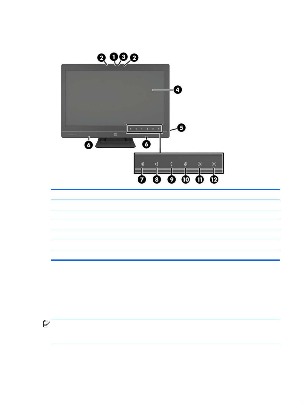
Front components
Component Component
1 Webcam (optional) with privacy shutter 7 Mute speaker
2 Dual microphone array (optional) 8 Reduce volume
3 Webcam activity LED (with optional webcam) 9 Increase volume
4 16:9 widescreen LED-backlit LCD display 10 Mute microphone
5 Power LED 11 Decrease brightness
6 High-performance stereo speakers 12 Increase brightness
Touch the icon area (7–12 above) to cause the icons to illuminate, then touch an icon to activate it.
To change the volume or brightness, touch and hold the appropriate icon or touch it and repeat until
the volume or brightness has reached the desired level.
To mute the speaker or microphone, just touch the appropriate icon. The icon remains illuminated until
you touch it again to reactivate the speaker or microphone.
NOTE: If you mute or reactivate the speaker in a software application, the icon illuminates or darkens
accordingly.
You cannot mute or reactivate the microphone from a software application.
Front components
3
Page 14
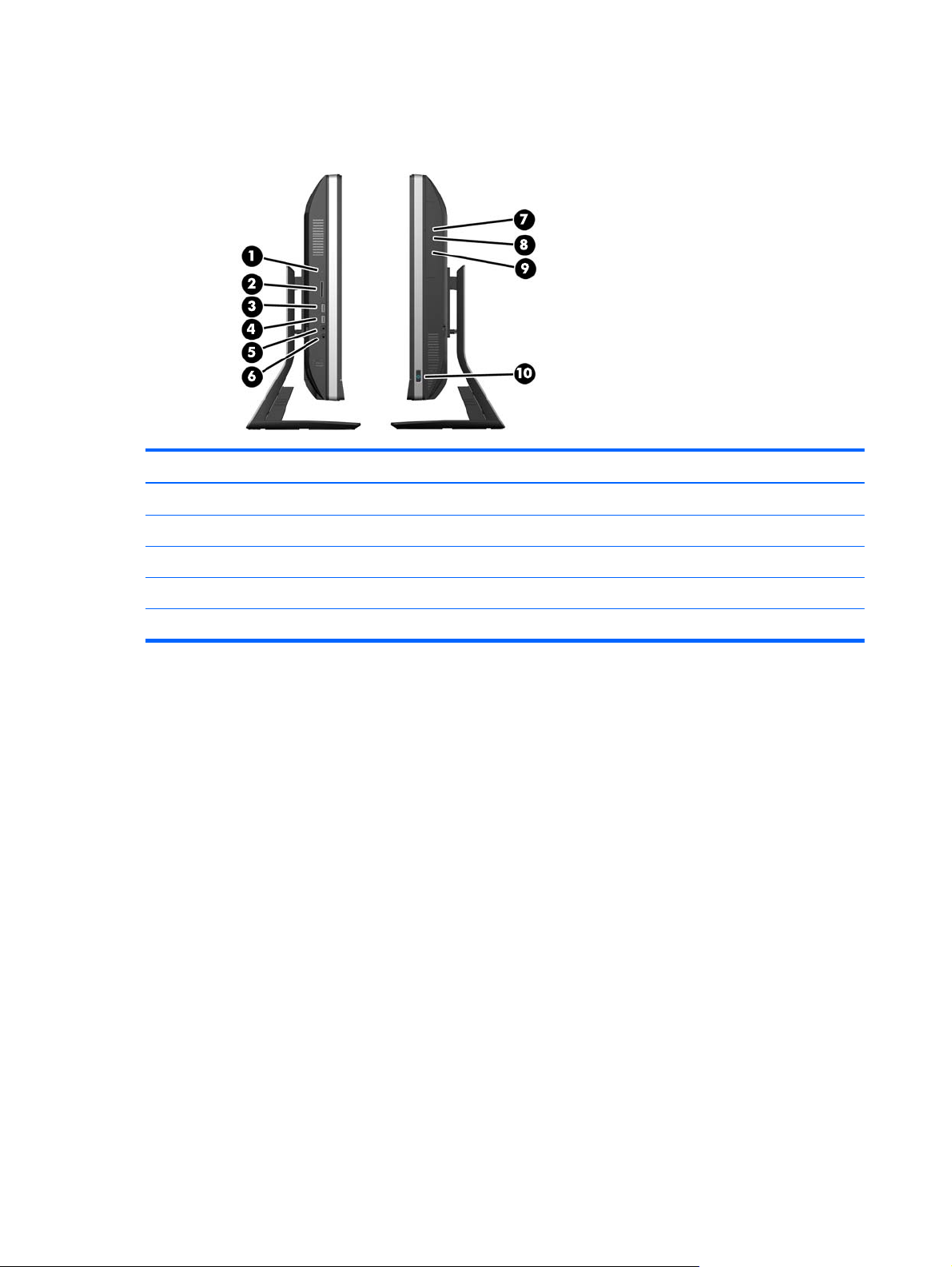
Side components
Component Component
1 Hard disc drive activity LED 6 Headset/line out jack
2 HP 5-in-1 media card reader (optional) 7 Tray-load optical disc drive
3 USB 3.0 port, fast-charging 8 Optical disc drive eject button
4 USB 3.0 port 9 Optical disc drive activity LED
5 Microphone/line in jack 10 Power button
4 Chapter 1 Product features
Page 15
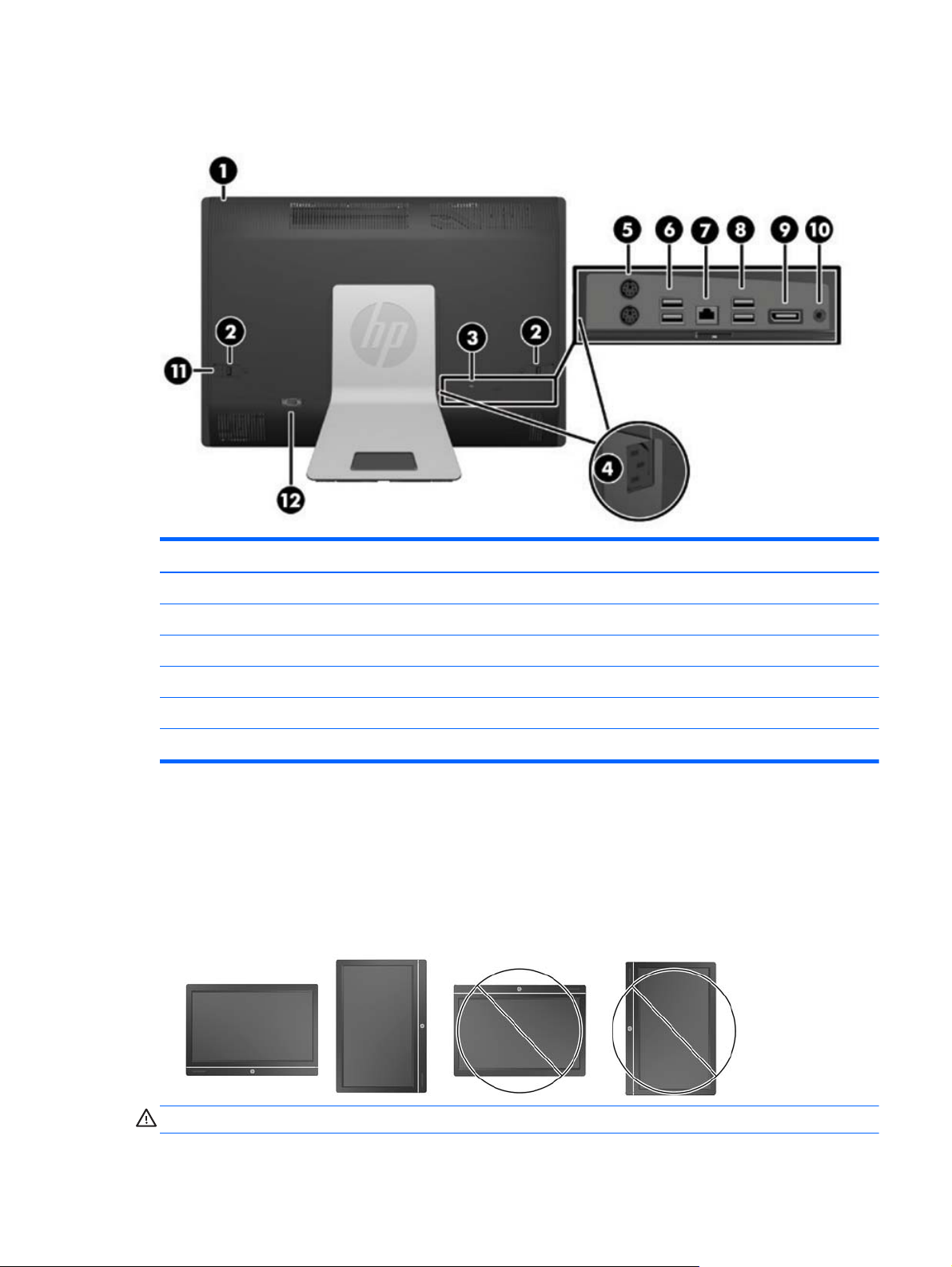
Rear components
Component Component
1 Access panel 7 RJ-45 Gigabit Ethernet port
2 Access panel latches 8 (2) USB 3.0 ports
3 Security lock slot 9 DisplayPort connector
4 Power connector 10 Stereo audio line out
5 (2) PS/2 mouse and keyboard connectors 11 Access panel security screw
6 (2) USB 3.0 ports 12 Serial port (optional)
Positioning the computer
This computer may be shipped with no stand, with a height-adjustable stand, or a tilt/swivel stand. The
computer may be placed in the landscape position with the HP logo on the bottom bezel or it may be
placed in the portrait position with the HP logo on the right side, as you face the computer.
Figure 1-1 Supported and unsupported positions
CAUTION: Positioning the computer with the HP logo on the top or on the left is not supported.
Rear components
5
Page 16
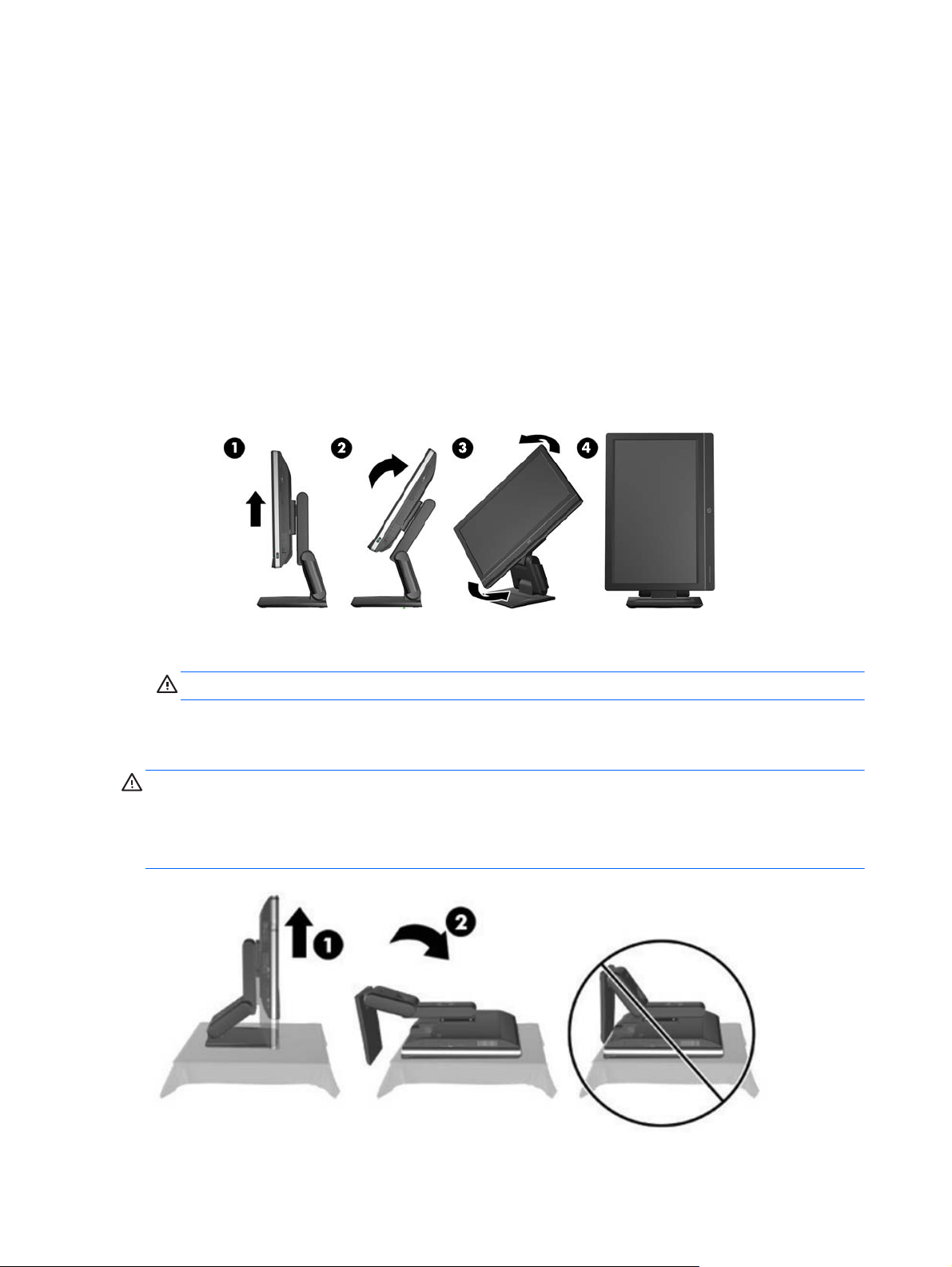
Adjusting the height-adjustable/recline stand (optional)
This stand allows you to:
adjust the computer height 110 mm (4.3 inches)
●
rotate the computer position from landscape to portrait
●
recline the computer backward up to +60 degrees
●
tilt the computer to 30 degrees from the desktop
●
swivel the computer up to 360 degrees right or left
●
To rotate the computer:
1. Grasp the computer by the sides and lift it straight up (1) to its highest position.
2. Press the top of the computer backwards (2).
CAUTION: The computer must be raised and tilted to provide clearance for rotating it.
3. Grasp the top right and bottom left of the computer and carefully turn it counterclockwise (3) until
it is in the portrait position (4).
WARNING! If the height-adjustable/recline stand is installed, before laying the computer down for
service, first grasp the sides of the display and raise the display to the highest position.
Do not lay the computer down with the sliding stand in the low position. The stand may suddenly
release, which could cause injury or damage to equipment.
6 Chapter 1 Product features
Page 17

2 Activating and Customizing the
Software
NOTE: This chapter provides information for both Windows 7 and Windows 8.
Activating and customizing the software in Windows 7
If your computer was not shipped with a Windows® operating system, some portions of this
documentation do not apply. Additional information is available in online help after you activate the
operating system.
CAUTION: Do not add optional hardware or third-party devices to the computer until the operating
system is successfully activated. Doing so may cause errors and prevent the operating system from
installing properly.
NOTE: Be sure there is a 10.2 cm (4 inch) clearance at the back of the unit and above the monitor to
permit the required airflow.
Activating the Windows operating system
The first time you turn on the computer, the operating system is set up and activated automatically. This
process takes about 5 to 10 minutes. Carefully read and follow the instructions on the screen to
complete the activation.
We recommend that you register your computer with HP during operating system setup so you can
receive important software updates, facilitate support questions, and sign up for special offers.
CAUTION: After the activation process has begun, DO NOT TURN OFF THE COMPUTER UNTIL THE
PROCESS IS COMPLETE. Turning off the computer during the activation process may damage the
software that runs the computer or prevent its proper installation.
NOTE: If the computer shipped with more than one operating system language on the hard drive, the
activation process could take up to 60 minutes.
Activating and customizing the software in Windows 7
7
Page 18

Downloading Windows 7 updates
Microsoft may release updates to the operating system. To help keep the computer running optimally,
HP recommends checking for the latest updates during the initial installation and periodically
throughout the life of the computer.
1. To set up your Internet connection, click Start > Internet Explorer and follow the instructions
on the screen.
2. After an Internet connection has been established, click the Start > All Programs > Windows
Update.
3. Run Windows Update monthly thereafter.
Installing or upgrading device drivers
When installing optional hardware devices after the operating system installation is complete, you must
also install the drivers for each of the devices.
In Windows 7, if prompted for the i386 directory, replace the path specification with C:\i386, or use
the Browse button in the dialog box to locate the i386 folder. This action points the operating system
to the appropriate drivers.
Obtain the latest support software, including support software for the operating system, from
http://www.hp.com/support. Select your country and language, select Download drivers and
software (and firmware), enter the model number of the computer, and press Enter.
Customizing the monitor display
If you wish, you can select or change the monitor refresh rates, screen resolution, color settings, font
sizes, and power management settings.
For more information, refer to the online documentation provided with the graphics controller utility or
the documentation that came with your monitor.
Right-click on the Windows desktop, then click Personalize to change display settings.
Activating and customizing the software in Windows 8
Additional information is available in online help after you activate the operating system.
NOTE: Be sure there is a 10.2 cm (4 inch) clearance at the back of the unit and above the monitor to
permit the required airflow.
Activating the Windows Operating System
The first time you turn on the computer, the operating system is set up and activated automatically. This
process takes about 5 to 10 minutes. Carefully read and follow the instructions on the screen to
complete the activation.
8 Chapter 2 Activating and Customizing the Software
Page 19

We recommend that you register your computer with HP during operating system set up so you can
receive important software updates, facilitate support questions, and sign up for special offers. You can
also register your computer with HP using the Register with HP app on the Start screen.
CAUTION: After the activation process has begun, DO NOT TURN OFF THE COMPUTER UNTIL THE
PROCESS IS COMPLETE. Turning off the computer during the activation process may damage the
software that runs the computer or prevent its proper installation.
Downloading Windows 8 updates
Microsoft may release updates to the operating system. To help keep the computer running optimally,
HP recommends checking for the latest updates during the initial installation and periodically
throughout the life of the computer.
Run Windows Update as soon as possible after you set up your computer.
1. Point to the upper-right or lower-right corner of the Start screen to display the charms.
2. Click Settings > Change PC Settings > Windows Update.
3. Run Windows Update monthly thereafter.
Customizing the monitor display
You can customize display settings for Windows 8 separately for the Start screen and the Desktop.
To customize the Start screen:
1. Point to the upper-right or lower-right corner of the Start screen to display the charms.
2. Click Settings > Change PC Settings.
3. Click Personalize to change the display settings.
To customize the Desktop:
1. Click the Desktop app on the Start screen.
2. Right-click on the desktop, and then click Personalize to change display settings.
Activating and customizing the software in Windows 8
9
Page 20
3 Illustrated parts catalog
System parts
NOTE: HP continually improves and changes product parts. For complete and current information on
supported parts for your computer, go to
then follow the on-screen instructions.
http://partsurfer.hp.com, select your country or region, and
10 Chapter 3 Illustrated parts catalog
Page 21
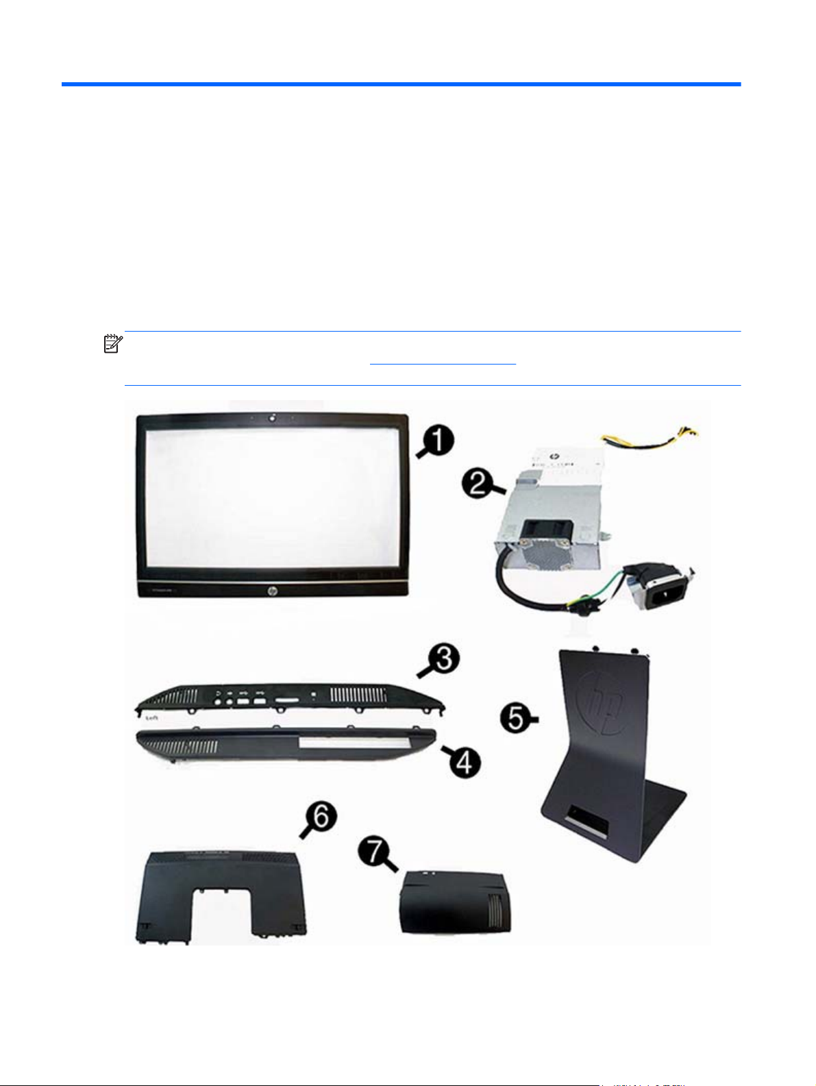
Item Description Spare part number
(1) Front bezel with camera lens 762610-001
(2) Power supply, 180-W 732494-001
(3) Left side panel 732489-001
(4) Right side panel 698193-001
(5) Standard stand assembly 732509-001
Height adjustment stand 698226-001
(6) Upper rear access panel (security screw and hardware are not spared) 698194-001
Lower rear access panel 762611-001
(7) Rear I/O cover 732492-001
Display panel 732495-001
Misc parts
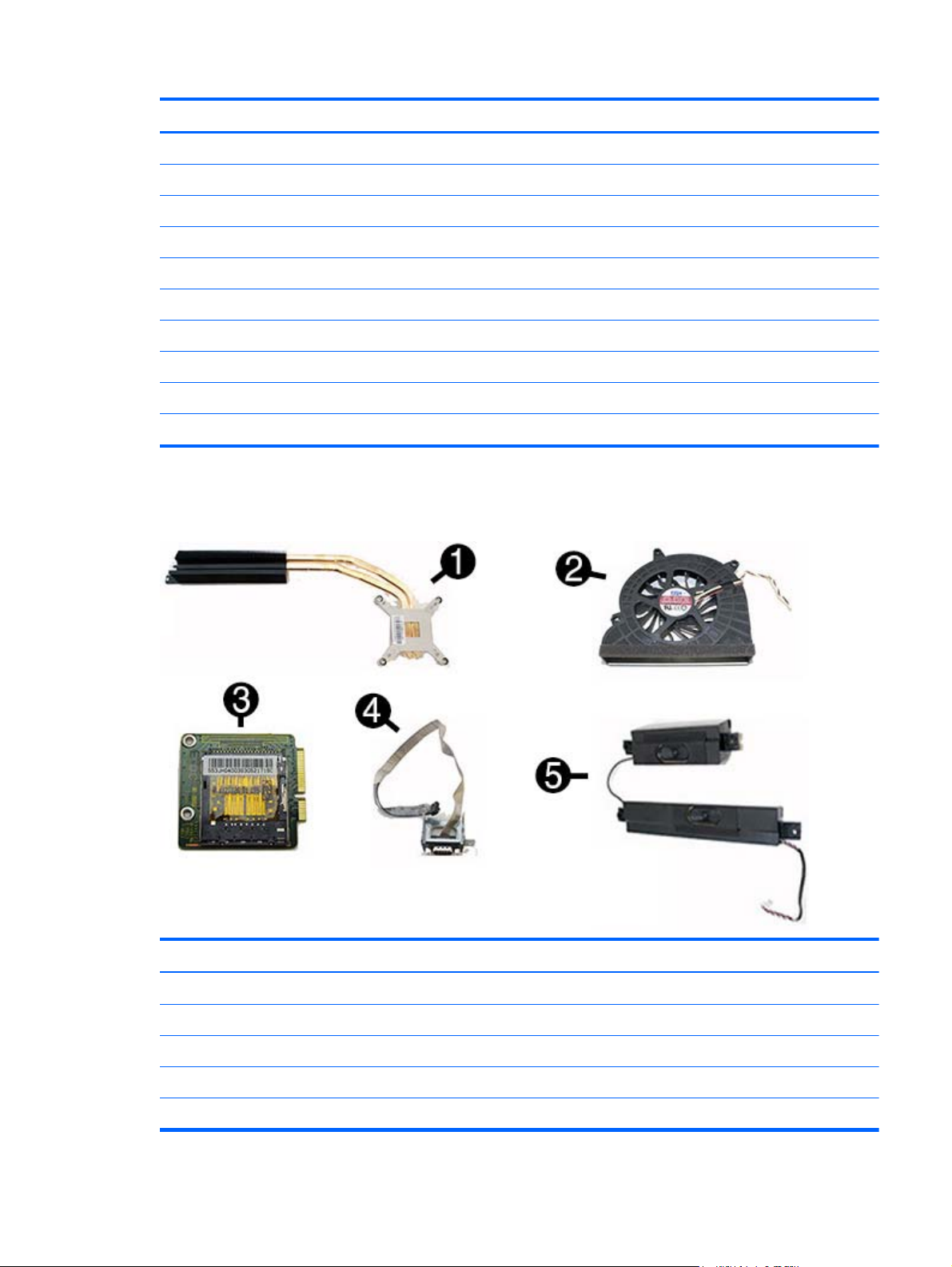
Item Description Spare part number
(1) Heat sink (thermal module) (includes replacement thermal material) 698201-001
(2) Fan 698196-001
(3) Card reader 732504-001
(4) Serial port assembly 698212-001
(5) Speakers (left and right) 698197-001
Misc parts
11
Page 22

Item Description Spare part number
Label for use in models without speakers 732508-001
Thermal pad 706867-001
HP ultraslim keyed cable lock 703372-001
Removable frame carrier, optical drive 732060-001
Card reader insert 698220-001
Card reader 732504-001
Hard drive isolation grommet 450712-001
Hard drive carrier, 2.5-inch to 3.5-inch 703597-001
Fan grommet 706866-001
Webcam assembly kit for models without a webcam (includes webcam
cover for bezel)
Antenna kit 698218-001
NFC assembly kit (holder, cable, antenna) for use with NFC controller,
spare part number 732503-001
Keyboards and mice
Description Spare part number
Keyboard (not illustrated)
PS/2 724718-xx1
USB 724720-xx1
Wireless with dongle 730323-xx1
Smartcard 700510-xx1
Smartcard, CCID 701671-xx1
Washable 701427-xx1
732511-001
769742-001
Mouse (not illustrated)
PS2, optical 674315-001
Washable 724795-001
USB, optical 674316-xx1
USB, laser 674318-xx1
12 Chapter 3 Illustrated parts catalog
Page 23

Mass storage devices
Description Spare part number
Optical drive (does not include bezel)
Blu-ray writer (BD-RE) drive 719157-001
DVD±RW drive 657958-001
DVD-ROM drive 608394-001
Removable frame carrier 732060-001
Hard drive (not illustrated)
2 TB, 7200 rpm hard drive 616608-001
1 TB, 7200 rpm hard drive 667719-001
1 TB, 7200 rpm hard drive, 2.5-inch, hybrid SSD 724937-001
500 GB, 7200 rpm hard drive, self-encrypting (SED) 696442-001
500 GB, 7200 rpm hard drive, 2.5-inch, hybrid SSD 724938-001
500 GB, 7200 rpm, hard drive, 3.5-inch 613208-001
500 GB, 7200 rpm, hard drive, 2.5-inch 761771-001
500 GB, 7200 rpm, hard drive, 2.5-inch, SED 762188-001
500 GB, 5400 rpm, hard drive, 2.5-inch, FIPS 748317-001
320 GB, 7200 rpm hard drive 761770-001
256 GB Solid State Drive (SSD) 680020-001
256 GB Solid State Drive (SSD), self-encrypting (SED) 746141-001
180 GB Solid State Drive (SSD), MLC 754076-001
128-GB solid-state drive 665961-001
128-GB solid-state drive, self-encrypting (SED) 746140-001
120-GB solid-state drive 661841-001
120 GB Solid State Drive (SSD), MLC 756459-001
32-GB mSATA drive 762612-001
32-GB mSATA drive, SRT 762613-001
Grommet, hard drive 594220-001
Mass storage devices
13
Page 24
Boards
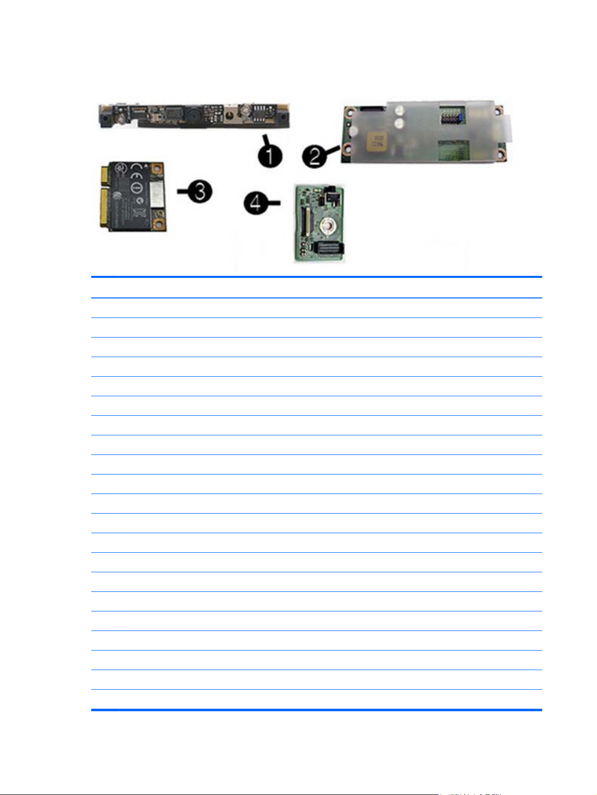
Item Description Spare part number
(1) Webcam module 732510-001
(2) Converter board 752122-001
(3) WLAN modules
HP WLAN 802.11 a/g/n, 2x2 701398-001
Intel Dual Band Wireless-N 7260NB 802.11 a/b/g/n 2x2 WiFi 717382-001
HP WLAN 802.11 a/b/g/n + Bluetooth 4.0 697316-001
(4) Power button board 732490-001
System board (not illustrated)
For use in non-Windows 8 models 758190-001
For use in models with Windows 8 Standard 758190-501
For use in models with Windows 8 Professional 758190-601
Memory modules (PC3-10600, 1333-MHz; not illustrated)
8-GB 689374-001
4-GB 689373-001
2-GB 689372-001
Processors (include replacement thermal material; not illustrated)
Intel Core i7-4790s (3.2-GHz, 8-MB L3 cache) 773554-001
Intel Core i7-4770s (3.1-GHz, 8-MB L3 cache) 732507-001
Intel Core i5-4690s (3.2-GHz, 6-MB L3 cache) 773083-001
Intel Core i5-4670s (3.1-GHz, 6-MB L3 cache) 732506-001
Intel Core i5-4590s (3.0-GHz, 6-MB L3 cache) 773082-001
14 Chapter 3 Illustrated parts catalog
Page 25

Item Description Spare part number
Intel Core i5-4570s (2.9-GHz, 6-MB L3 cache) 732505-001
Intel Core i3-4360 (3.7-GHz, 4-MB L3 cache) 769735-001
Intel Core i3-4350 (3.6-GHz, 4-MB L3 cache) 769734-001
Intel Core i3-4340 (3.6-GHz, 4-MB L3 cache) 742562-001
Intel Core i3-4330 (3.5-GHz, 4-MB L3 cache) 742561-001
Intel Core i3-4150 (3.5-GHz, 3-MB L3 cache) 769733-001
Intel Core i3-4130 (3.4-GHz, 3-MB L3 cache) 742560-001
Intel Pentium G3450 (3.4-GHz, 3-MB L3 cache) 769741-001
Intel Pentium G3440 (3.3-GHz, 3-MB L3 cache) 769740-001
Intel Pentium G3430 (3.3-GHz, 3-MB L3 cache) 742566-001
Intel Pentium G3420 (3.2-GHz, 3-MB L3 cache) 742565-001
Intel Pentium G3240 (3.1-GHz, 3-MB L3 cache) 769739-001
Intel Pentium G3220 (3.0-GHz, 3-MB L3 cache) 742564-001
Intel Celeron G1850 (2.9-GHz, 2-MB L3 cache) 769732-001
Intel Celeron G1840 (2.8-GHz, 2-MB L3 cache) 769731-001
Intel Celeron G1830 (2.8-GHz, 2-MB L3 cache) 758757-001
Intel Celeron G1820 (2.7-GHz, 2-MB L3 cache) 758756-001
Boards
15
Page 26
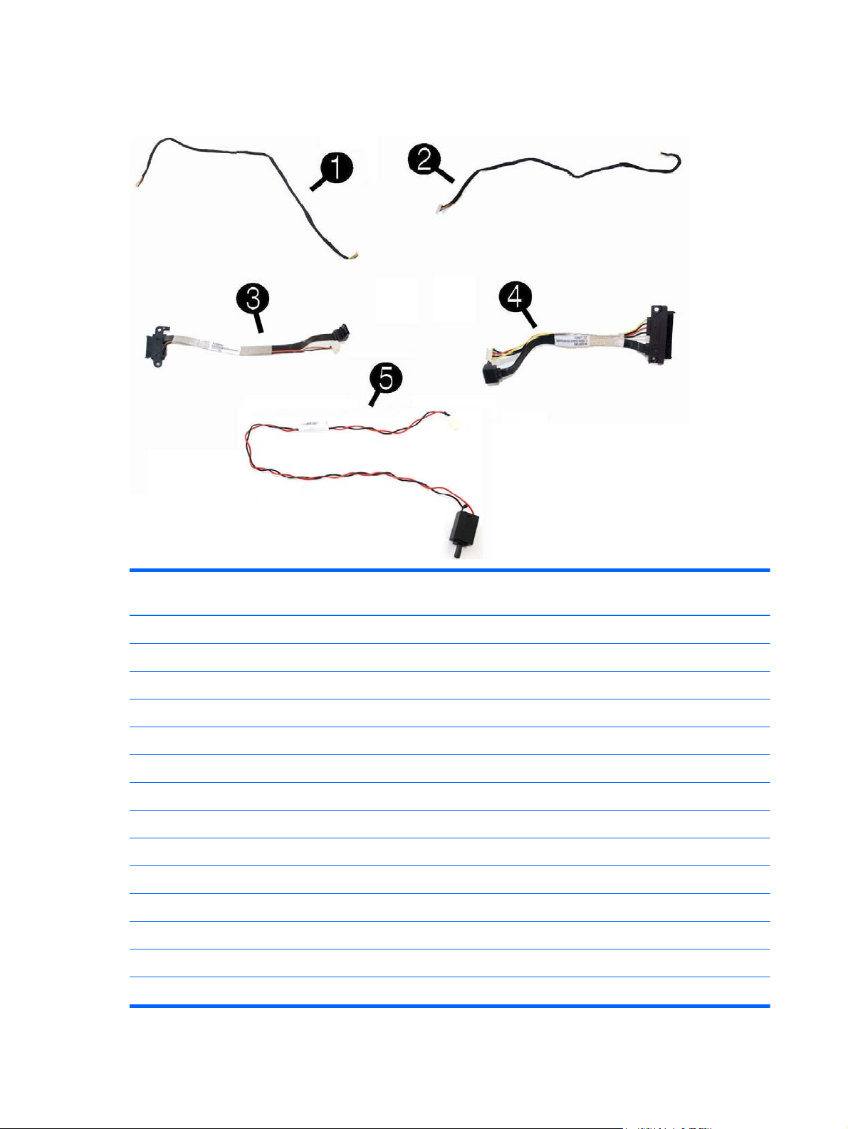
Cables
Description Spare part
number
(1) Power button board cable 698208-001
(2) Backlight cable 732496-001
(3) Optical drive cable (data and power assembly) 698221-001
(4) Hard drive cable (data and power assembly) 698215-001
(5) Intrusion sensor with cable 688665-001
2nd hard drive cable 698216-001
Converter board side cable (not illustrated) 698206-001
LVDS (display) cable 761785-001
Capacitive strip sensor cable 698210-001
Webcam cable 698211-001
Adapter, DisplayPort to VGA 603250-001
Adapter, DisplayPort to DVI 662723-001
Adapter, DisplayPort to HDMI 617450-001
DisplayPort cable 487562-001
16 Chapter 3 Illustrated parts catalog
Page 27

Sequential part number listing
Spare part
number
450712-001 Grommet, hard drive isolation
487562-001 DisplayPort cable
594220-001 Grommet, hard drive
603250-001 Adapter, DisplayPort to VGA
608394-001 DVD-ROM drive
613208-001 500 GB, 7200 rpm, hard drive, 3.5-inch
616608-001 2 TB, 7200 rpm hard drive
617450-001 Adapter, DisplayPort to HDMI
657958-001 Keyboard, USB hub
661841-001 120 GB Solid State Drive (SSD)
662723-001 Adapter, DisplayPort to DVI
665961-001 128 GB Solid State Drive (SSD)
667719-001 1 TB, 7200 rpm hard drive
674315-001 Mouse, PS2, optical
Description
674316-001 Mouse, USB, optical
674318-001 Mouse, USB, laser
680020-001 256 GB Solid State Drive (SSD)
688665-001 Intrusion sensor with cable
689372-001 4-GB memory module (PC3-10600, 1600-MHz)
689373-001 2-GB memory module (PC3-10600, 1600-MHz)
689374-001 8-GB memory module (PC3-10600, 1600-MHz)
696442-001 500 GB, 7200 rpm hard drive, self-encrypting (SED)
697316-001 HP WLAN 802.11 a/b/g/n + Bluetooth 4.0
698193-001 Right side panel
698194-001 Upper rear access panel (security screw and hardware are not spared)
698196-001 Fan
698197-001 Speakers (left and right)
698201-001 Heat sink (thermal module) for use with the processor (includes replacement thermal material)
698206-001 Converter board side cable
698208-001 Power button board cable
Sequential part number listing
17
Page 28

Spare part
number
698210-001 Capacitive strip sensor cable
698211-001 Webcam cable
698212-001 Serial port assembly
698215-001 Hard drive cable (data and power assembly)
698216-001 2nd hard drive cable
698220-001 Card reader insert
698221-001 Optical drive cable (data and power assembly)
698226-001 Height adjustment stand
700510-001 Keyboard, washable, for use in the United States
700510-121 Keyboard, washable, for use in French Canada
700510-161 Keyboard, washable, for use in Latin America
700510-201 Keyboard, washable, for use in Brazil
701398-001 HP WLAN 802.11 a/g/n, 2x2
701427-001 Keyboard, USB, Smartcard, for use in the United States
Description
701427-031 Keyboard, USB, Smartcard, for use in the United Kingdom
701427-041 Keyboard, USB, Smartcard, for use in Germany
701427-051 Keyboard, USB, Smartcard, for use in France
701427-061 Keyboard, USB, Smartcard, for use in Italy
701427-071 Keyboard, USB, Smartcard, for use in Spain
701427-081 Keyboard, USB, Smartcard, for use in Denmark
701427-091 Keyboard, USB, Smartcard, for use in Norway
701427-101 Keyboard, USB, Smartcard, for use in Switzerland
701427-111 Keyboard, USB, Smartcard, for use in Sweden
701427-121 Keyboard, USB, Smartcard, for use in French Canada
701427-131 Keyboard, USB, Smartcard, for use in Portugal
701427-141 Keyboard, USB, Smartcard, for use in Turkey
701427-151 Keyboard, USB, Smartcard, for use in Greece
701427-161 Keyboard, USB, Smartcard, for use in Latin America
701427-171 Keyboard, USB, Smartcard, for use in Saudi Arabia
701427-181 Keyboard, USB, Smartcard, for use in Belgium
701427-201 Keyboard, USB, Smartcard, for use in Brazil
701427-211 Keyboard, USB, Smartcard, for use in Hungary
18 Chapter 3 Illustrated parts catalog
Page 29

Spare part
number
701427-221 Keyboard, USB, Smartcard, for use in the Czech Republic and Slovakia
701427-231 Keyboard, USB, Smartcard, for use in Slovenia
701427-251 Keyboard, USB, Smartcard, for use in Russia
701427-261 Keyboard, USB, Smartcard, for use in Bulgaria
701427-271 Keyboard, USB, Smartcard, for use in Romania
701427-281 Keyboard, USB, Smartcard, for use in Thailand
701427-291 Keyboard, USB, Smartcard, for use in Japan
701427-371 Keyboard, USB, Smartcard, for use internationally
701427-AA1 Keyboard, USB, Smartcard, for use in the People’s Republic of China
701427-AB1 Keyboard, USB, Smartcard, for use in Taiwan
701427-B41 Keyboard, USB, Smartcard, for use in BHCSY
701427-BB1 Keyboard, USB, Smartcard, for use in Israel
701427-DE1 Keyboard, USB, Smartcard, for use in French Arabia
701427-KD1 Keyboard, USB, Smartcard, for use in South Korea
Description
701427-L31 Keyboard, USB, Smartcard, for use with international English
701671-001 Keyboard, USB, Smartcard, CCID, for use in the United States
701671-031 Keyboard, USB, Smartcard, CCID, for use in the United Kingdom
701671-041 Keyboard, USB, Smartcard, CCID, for use in Germany
701671-051 Keyboard, USB, Smartcard, CCID, for use in France
701671-061 Keyboard, USB, Smartcard, CCID, for use in Italy
701671-071 Keyboard, USB, Smartcard, CCID, for use in Spain
701671-081 Keyboard, USB, Smartcard, CCID, for use in Denmark
701671-091 Keyboard, USB, Smartcard, CCID, for use in Norway
701671-101 Keyboard, USB, Smartcard, CCID, for use in Switzerland
701671-111 Keyboard, USB, Smartcard, CCID, for use in Sweden
701671-121 Keyboard, USB, Smartcard, CCID, for use in French Canada
701671-131 Keyboard, USB, Smartcard, CCID, for use in Portugal
701671-141 Keyboard, USB, Smartcard, CCID, for use in Turkey
701671-151 Keyboard, USB, Smartcard, CCID, for use in Greece
701671-161 Keyboard, USB, Smartcard, CCID, for use in Latin America
701671-171 Keyboard, USB, Smartcard, CCID, for use in Saudi Arabia
701671-181 Keyboard, USB, Smartcard, CCID, for use in Belgium
Sequential part number listing
19
Page 30

Spare part
number
701671-201 Keyboard, USB, Smartcard, CCID, for use in Brazil
701671-211 Keyboard, USB, Smartcard, CCID, for use in Hungary
701671-221 Keyboard, USB, Smartcard, CCID, for use in the Czech Republic and Slovakia
701671-231 Keyboard, USB, Smartcard, CCID, for use in Slovenia
701671-251 Keyboard, USB, Smartcard, CCID, for use in Russia
701671-261 Keyboard, USB, Smartcard, CCID, for use in Bulgaria
701671-271 Keyboard, USB, Smartcard, CCID, for use in Romania
701671-281 Keyboard, USB, Smartcard, CCID, for use in Thailand
701671-291 Keyboard, USB, Smartcard, CCID, for use in Japan
701671-371 Keyboard, USB, Smartcard, CCID, for use internationally
701671-AA1 Keyboard, USB, Smartcard, CCID, for use in the People’s Republic of China
701671-AB1 Keyboard, USB, Smartcard, CCID, for use in Taiwan
701671-B41 Keyboard, USB, Smartcard, CCID, for use in BHCSY
701671-BB1 Keyboard, USB, Smartcard, CCID, for use in Israel
Description
701671-DE1 Keyboard, USB, Smartcard, CCID, for use in French Arabia
701671-KD1 Keyboard, USB, Smartcard, CCID, for use in South Korea
701671-L31 Keyboard, USB, Smartcard, CCID, for use with international English
703372-001 HP ultraslim keyed cable lock
703597-001 Hard drive carrier, 2.5-inch to 3.5-inch
706866-001 Fan grommet
706867-001 Thermal pad
717382-001 Intel Dual Band Wireless-N 7260NB 802.11 a/b/g/n 2x2 WiFi
719157-001 Blu-ray writer (BD-RE) drive
724718-001 Keyboard, PS/2, for use in the United States
724718-031 Keyboard, PS/2, for use in the United Kingdom
724718-041 Keyboard, PS/2, for use in Germany
724718-051 Keyboard, PS/2, for use in France
724718-061 Keyboard, PS/2, for use in Italy
724718-071 Keyboard, PS/2, for use in Spain
724718-081 Keyboard, PS/2, for use in Denmark
724718-091 Keyboard, PS/2, for use in Norway
724718-101 Keyboard, PS/2, for use in Switzerland
20 Chapter 3 Illustrated parts catalog
Page 31

Spare part
number
724718-111 Keyboard, PS/2, for use in Sweden
724718-121 Keyboard, PS/2, for use in French Canada
724718-131 Keyboard, PS/2, for use in Portugal
724718-141 Keyboard, PS/2, for use in Turkey
724718-151 Keyboard, PS/2, for use in Greece
724718-161 Keyboard, PS/2, for use in Latin America
724718-171 Keyboard, PS/2, for use in Saudi Arabia
724718-181 Keyboard, PS/2, for use in Belgium
724718-201 Keyboard, PS/2, for use in Brazil
724718-211 Keyboard, PS/2, for use in Hungary
724718-221 Keyboard, PS/2, for use in the Czech Republic and Slovakia
724718-231 Keyboard, PS/2, for use in Slovenia
724718-251 Keyboard, PS/2, for use in Russia
724718-261 Keyboard, PS/2, for use in Bulgaria
Description
724718-271 Keyboard, PS/2, for use in Romania
724718-281 Keyboard, PS/2, for use in Thailand
724718-291 Keyboard, PS/2, for use in Japan
724718-AA1 Keyboard, PS/2, for use in the People’s Republic of China
724718-AB1 Keyboard, PS/2, for use in Taiwan
724718-B41 Keyboard, PS/2, for use in BHCSY
724718-BB1 Keyboard, PS/2, for use in Israel
724718-D61 Keyboard, PS/2, for use in India
724718-DE1 Keyboard, PS/2, for use in French Arabia
724718-KD1 Keyboard, PS/2, for use in South Korea
724718-L31 Keyboard, PS/2, for use with International English
724720-001 Keyboard, USB for use in the United States
724720-031 Keyboard, USB, for use in the United Kingdom
724720-041 Keyboard, USB, for use in Germany
724720-051 Keyboard, USB, for use in France
724720-061 Keyboard, USB, for use in Italy
724720-071 Keyboard, USB, for use in Spain
724720-081 Keyboard, USB, for use in Denmark
Sequential part number listing
21
Page 32

Spare part
number
724720-091 Keyboard, USB, for use in Norway
724720-101 Keyboard, USB, for use in Switzerland
724720-111 Keyboard, USB, for use in Sweden
724720-121 Keyboard, USB, for use in French Canada
724720-131 Keyboard, USB, for use in Portugal
724720-141 Keyboard, USB, for use in Turkey
724720-151 Keyboard, USB, for use in Greece
724720-161 Keyboard, USB, for use in Latin America
724720-171 Keyboard, USB, for use in Saudi Arabia
724720-181 Keyboard, USB, for use in Belgium
724720-201 Keyboard, USB, for use in Brazil
724720-211 Keyboard, USB, for use in Hungary
724720-221 Keyboard, USB, for use in the Czech Republic and Slovakia
724720-231 Keyboard, USB, for use in Slovenia
Description
724720-251 Keyboard, USB, for use in Russia
724720-261 Keyboard, USB, for use in Bulgaria
724720-271 Keyboard, USB, for use in Romania
724720-281 Keyboard, USB, for use in Thailand
724720-291 Keyboard, USB, for use in Japan
724720-AA1 Keyboard, USB, for use in the People’s Republic of China
724720-AB1 Keyboard, USB, for use in Taiwan
724720-B41 Keyboard, USB, for use in BHCSY
724720-BB1 Keyboard, USB, for use in Israel
724720-D61 Keyboard, USB, for use in India
724720-DE1 Keyboard, PS/2, for use in French Arabia
724720-KD1 Keyboard, USB, for use in South Korea
724720-L31 Keyboard, USB, for use with International English
724795-001 Mouse, washable
724937-001 Hard drive, 1 TB, 2.5-inch, hybrid SSD
724938-001 500 GB, 7200 rpm hard drive, 2.5-inch, hybrid SSD
730323-001 Keyboard, wireless with mouse and dongle, for use in the United States
730323-031 Keyboard, wireless with mouse and dongle, for use in the United Kingdom
22 Chapter 3 Illustrated parts catalog
Page 33

Spare part
number
730323-041 Keyboard, wireless with mouse and dongle, for use in Germany
730323-051 Keyboard, wireless with mouse and dongle, for use in France
730323-061 Keyboard, wireless with mouse and dongle, for use in Italy
730323-071 Keyboard, wireless with mouse and dongle, for use in Spain
730323-081 Keyboard, wireless with mouse and dongle, for use in Denmark
730323-091 Keyboard, wireless with mouse and dongle, for use in Norway
730323-101 Keyboard, wireless with mouse and dongle, for use in Switzerland
730323-111 Keyboard, wireless with mouse and dongle, for use in Sweden
730323-121 Keyboard, wireless with mouse and dongle, for use in French Canada
730323-131 Keyboard, wireless with mouse and dongle, for use in Portugal
730323-141 Keyboard, wireless with mouse and dongle, for use in turkey
730323-151 Keyboard, wireless with mouse and dongle, for use in Greece
730323-161 Keyboard, wireless with mouse and dongle, for use in Latin America
730323-171 Keyboard, wireless with mouse and dongle, for use in Saudi Arabia
Description
730323-181 Keyboard, wireless with mouse and dongle, for use in Belgium
730323-201 Keyboard, wireless with mouse and dongle, for use in Brazil
730323-211 Keyboard, wireless with mouse and dongle, for use in Hungary
730323-221 Keyboard, wireless with mouse and dongle, for use in the Czech Republic and Slovakia
730323-231 Keyboard, wireless with mouse and dongle, for use in Slovenia
730323-251 Keyboard, wireless with mouse and dongle, for use in Russia
730323-261 Keyboard, wireless with mouse and dongle, for use in Bulgaria
730323-271 Keyboard, wireless with mouse and dongle, for use in Romania
730323-281 Keyboard, wireless with mouse and dongle, for use in Thailand
730323-291 Keyboard, wireless with mouse and dongle, for use in Japan
730323-AA1 Keyboard, wireless with mouse and dongle, for use in the People’s Republic of China
730323-AB1 Keyboard, wireless with mouse and dongle, for use in Taiwan
730323-B41 Keyboard, wireless with mouse and dongle, for use in BHCSY
730323-BB1 Keyboard, wireless with mouse and dongle, for use in Israel
730323-D61 Keyboard, wireless with mouse and dongle, for use in India
730323-DE1 Keyboard, wireless with mouse and dongle, for use in French Arabia
730323-KD1 Keyboard, wireless with mouse and dongle, for use in South Korea
730323-L31 Keyboard, wireless with mouse and dongle, for use with International English
Sequential part number listing
23
Page 34

Spare part
number
732060-001 Removable frame carrier, optical drive
732489-001 Left side panel
732490-001 Power button board
732492-001 Rear I/O cover
732494-001 Power supply, 180W
732495-001 Display panel, WLED
732496-001 Backlight cable
732503-001 Near field communication (NFC) NXP controller (use with NFC assembly kit, spare part number 769742-001)
732504-001 Card reader
732505-001 Intel Core i5, 4570s processor (3.4-GHz, 8-MB L3 cache)
732506-001 Intel Core i5, 4670s processor (3.3-GHz, 6-MB L3 cache)
732507-001 Intel Core i7, 4770s processor (3.1-GHz, 6-MB L3 cache)
732508-001 Label for use in models without speakers
732509-001 Standard stand assembly
Description
732510-001 Webcam module
698218-001 Antenna kit
732511-001 Webcam assembly kit for models without a webcam (includes webcam cover for bezel)
769742-001 NFC assembly kit (holder, cable, antenna) for use with NFC controller, spare part number 732503-001
742560-001 Intel Core i3-4130 processor (3.4 GHz, 4 MB cache)
742561-001 Intel Core i3-4330 processor (3.5 GHz, 4 MB cache)
742562-001 Intel Core i3-4340 processor (3.6 GHz, 4 MB cache)
742564-001 Intel Pentium G3220 processor (3.0 GHz, 3 MB cache)
742565-001 Intel Pentium G3420 processor (3.2 GHz, 3 MB cache)
742566-001 Intel Pentium G3430 processor (3.3 GHz, 3 MB cache)
746140-001 128-GB solid-state drive, self-encrypting (SED)
746141-001 256-GB solid-state drive, self-encrypting (SED)
748317-001 500-GB, 5400 rpm hard drive, 2.5-inch, FIPS
752122-001 Converter board
754076-001 180-GB solid-state drive, MLC
756459-001 120-GB solid-state drive, MLC
758190-001 System board for use in models without Windows 8
758190-501 System board for use in models with Windows 8 Standard
24 Chapter 3 Illustrated parts catalog
Page 35

Spare part
number
758190-601 System board for use in models with Windows 8 Professional
758756-001
758757-001
761770-001 320 GB, 7200 rpm hard drive
761785-001 LVDS (display) cable
762188-001 500-GB, 7200 rpm hard drive, 2.5-inch, Self-encrypting drive (SED)
762610-001 Front bezel with camera lens
762611-001 Lower rear access panel
762612-001 32-GB mSATA drive
762613-001 32-GB mSATA drive, SRT
769731-001 Intel Celeron G1840 processor (2.8-GHz, 2-MB L3 cache)
769732-001 Intel Celeron G1850 processor (2.9-GHz, 2-MB L3 cache)
769733-001 Intel Core i3-4150 processor (3.5-GHz, 3-MB L3 cache)
769734-001 Intel Core i3-4350 processor (3.6-GHz, 4-MB L3 cache)
Description
769735-001 Intel Core i3-4360 processor (3.7-GHz, 4-MB L3 cache)
769739-001 Intel Pentium G3440 processor (3.3-GHz, 3-MB L3 cache)
769740-001 Intel Pentium G3440 processor (3.3-GHz, 3-MB L3 cache)
769741-001 Intel Pentium G3450 processor (3.4-GHz, 3-MB L3 cache)
773082-001 Intel Core i5-4590s processor (3.0-GHz, 6-MB L3 cache)
773083-001 Intel Core i5-4690s processor (3.2-GHz, 6-MB L3 cache)
773554-001 Intel Core i7-4790s processor (3.2-GHz, 8-MB L3 cache)
Sequential part number listing
25
Page 36

4 Routine care, SATA drive
guidelines, and disassembly
preparation
This chapter provides general service information for the computer. Adherence to the procedures and
precautions described in this chapter is essential for proper service.
CAUTION: When the computer is plugged into an AC power source, voltage is always applied to
the system board. You must disconnect the power cord from the power source before opening the
computer to prevent system board or component damage.
Electrostatic discharge information
A sudden discharge of static electricity from your finger or other conductor can destroy static-sensitive
devices or microcircuitry. Often the spark is neither felt nor heard, but damage occurs. An electronic
device exposed to electrostatic discharge (ESD) may not appear to be affected at all and can work
perfectly throughout a normal cycle. The device may function normally for a while, but it has been
degraded in the internal layers, reducing its life expectancy.
Networks built into many integrated circuits provide some protection, but in many cases, the discharge
contains enough power to alter device parameters or melt silicon junctions.
26 Chapter 4 Routine care, SATA drive guidelines, and disassembly preparation
Page 37

Generating static
The following table shows that:
Different activities generate different amounts of static electricity.
●
Static electricity increases as humidity decreases.
●
Relative Humidity
Event 55% 40% 10%
Walking across carpet
Walking across vinyl floor
Motions of bench worker
Removing DIPs from plastic tube
Removing DIPs from vinyl tray
Removing DIPs from Styrofoam
Removing bubble pack from PCB
Packing PCBs in foam-lined box
These are then multi-packaged inside plastic tubes, trays, or Styrofoam.
7,500 V
3,000 V
400 V
400 V
2,000 V
3,500 V
7,000 V
5,000 V
NOTE: 700 volts can degrade a product.
Preventing electrostatic damage to equipment
Many electronic components are sensitive to ESD. Circuitry design and structure determine the degree
of sensitivity. The following packaging and grounding precautions are necessary to prevent damage to
electric components and accessories.
15,000 V
5,000 V
800 V
700 V
4,000 V
5,000 V
20,000 V
11,000 V
35,000 V
12,000 V
6,000 V
2,000 V
11,500 V
14,500 V
26,500 V
21,000 V
To avoid hand contact, transport products in static-safe containers such as tubes, bags, or boxes.
●
Protect all electrostatic parts and assemblies with conductive or approved containers or
●
packaging.
Keep electrostatic sensitive parts in their containers until they arrive at static-free stations.
●
Place items on a grounded surface before removing them from their container.
●
Always be properly grounded when touching a sensitive component or assembly.
●
Avoid contact with pins, leads, or circuitry.
●
Place reusable electrostatic-sensitive parts from assemblies in protective packaging or conductive
●
foam.
Electrostatic discharge information
27
Page 38

Personal grounding methods and equipment
Use the following equipment to prevent static electricity damage to equipment:
Wrist straps are flexible straps with a maximum of one-megohm ± 10% resistance in the ground
●
cords. To provide proper ground, a strap must be worn snug against bare skin. The ground cord
must be connected and fit snugly into the banana plug connector on the grounding mat or
workstation.
Heel straps/Toe straps/Boot straps can be used at standing workstations and are
●
compatible with most types of shoes or boots. On conductive floors or dissipative floor mats, use
them on both feet with a maximum of one-megohm ± 10% resistance between the operator and
ground.
Static Shielding Protection Levels
Method Voltage
Antistatic plastic
Carbon-loaded plastic
Metallized laminate
Grounding the work area
To prevent static damage at the work area, use the following precautions:
Cover the work surface with approved static-dissipative material. Provide a wrist strap connected
●
to the work surface and properly grounded tools and equipment.
Use static-dissipative mats, foot straps, or air ionizers to give added protection.
●
Handle electrostatic sensitive components, parts, and assemblies by the case or PCB laminate.
●
Handle them only at static-free work areas.
Turn off power and input signals before inserting and removing connectors or test equipment.
●
Use fixtures made of static-safe materials when fixtures must directly contact dissipative surfaces.
●
Keep work area free of nonconductive materials such as ordinary plastic assembly aids and
●
Styrofoam.
1,500
7,500
15,000
Use field service tools, such as cutters, screwdrivers, and vacuums, that are conductive.
●
Recommended materials and equipment
Materials and equipment that are recommended for use in preventing static electricity include:
Antistatic tape
●
Antistatic smocks, aprons, or sleeve protectors
●
Conductive bins and other assembly or soldering aids
●
28 Chapter 4 Routine care, SATA drive guidelines, and disassembly preparation
Page 39

Conductive foam
●
Conductive tabletop workstations with ground cord of one-megohm +/- 10% resistance
●
Static-dissipative table or floor mats with hard tie to ground
●
Field service kits
●
Static awareness labels
●
Wrist straps and footwear straps providing one-megohm +/- 10% resistance
●
Material handling packages
●
Conductive plastic bags
●
Conductive plastic tubes
●
Conductive tote boxes
●
Opaque shielding bags
●
Transparent metallized shielding bags
●
Transparent shielding tubes
●
Operating guidelines
To prevent overheating and to help prolong the life of the computer:
Keep the computer away from excessive moisture, direct sunlight, and extremes of heat and cold.
●
Operate the computer on a sturdy, level surface. Leave a 10.2-cm (4-inch) clearance on all vented
●
sides of the computer and above the monitor to permit the required airflow.
Never restrict the airflow into the computer by blocking any vents or air intakes. Do not place the
●
keyboard, with the keyboard feet down, directly against the front of the desktop unit as this also
restricts airflow.
Occasionally clean the air vents on all vented sides of the computer. Lint, dust, and other foreign
●
matter can block the vents and limit the airflow. Be sure to unplug the computer before cleaning
the air vents.
Never operate the computer with the cover or side panel removed.
●
Do not stack computers on top of each other or place computers so near each other that they are
●
subject to each other’s re-circulated or preheated air.
If the computer is to be operated within a separate enclosure, intake and exhaust ventilation must
●
be provided on the enclosure, and the same operating guidelines listed above will still apply.
Keep liquids away from the computer and keyboard.
●
Operating guidelines
29
Page 40

Never cover the ventilation slots on the monitor with any type of material.
●
Install or enable power management functions of the operating system or other software, including
●
sleep states.
Routine care
General cleaning safety precautions
1. Never use solvents or flammable solutions to clean the computer.
2. Never immerse any parts in water or cleaning solutions; apply any liquids to a clean cloth and
then use the cloth on the component.
3. Always unplug the computer when cleaning with liquids or damp cloths.
4. Always unplug the computer before cleaning the keyboard, mouse, or air vents.
5. Disconnect the keyboard before cleaning it.
6. Wear safety glasses equipped with side shields when cleaning the keyboard.
Cleaning the Computer Case
Follow all safety precautions in General cleaning safety precautions on page 30 before cleaning the
computer.
To clean the computer case, follow the procedures described below:
To remove light stains or dirt, use plain water with a clean, lint-free cloth or swab.
●
For stronger stains, use a mild dishwashing liquid diluted with water. Rinse well by wiping it with
●
a cloth or swab dampened with clear water.
For stubborn stains, use isopropyl (rubbing) alcohol. No rinsing is needed as the alcohol will
●
evaporate quickly and not leave a residue.
After cleaning, always wipe the unit with a clean, lint-free cloth.
●
Occasionally clean the air vents on the computer. Lint and other foreign matter can block the vents
●
and limit the airflow.
Cleaning the keyboard
Follow all safety precautions in General cleaning safety precautions on page 30 before cleaning the
keyboard.
To clean the tops of the keys or the keyboard body, follow the procedures described in
Computer Case on page 30.
When cleaning debris from under the keys, review all rules in
on page 30 before following these procedures:
30 Chapter 4 Routine care, SATA drive guidelines, and disassembly preparation
General cleaning safety precautions
Cleaning the
Page 41

CAUTION: Use safety glasses equipped with side shields before attempting to clean debris from
under the keys.
Visible debris underneath or between the keys may be removed by vacuuming or shaking.
●
Canned, pressurized air may be used to clean debris from under the keys. Caution should be used
●
as too much air pressure can dislodge lubricants applied under the wide keys.
If you remove a key, use a specially designed key puller to prevent damage to the keys. This tool
●
is available through many electronic supply outlets.
CAUTION: Never remove a wide leveled key (like the space bar) from the keyboard. If these
keys are improperly removed or installed, the keyboard may not function properly.
Cleaning under a key may be done with a swab moistened with isopropyl alcohol and squeezed
●
out. Be careful not to wipe away lubricants necessary for proper key functions. Use tweezers to
remove any fibers or dirt in confined areas. Allow the parts to air dry before reassembly.
Cleaning the monitor
Wipe the monitor screen with a clean cloth moistened with water or with a towelette designed for
●
cleaning monitors. Do not use sprays or aerosols directly on the screen; the liquid may seep into
the housing and damage a component. Never use solvents or flammable liquids on the monitor.
To clean the monitor body follow the procedures in
●
Cleaning the mouse
Before cleaning the mouse, ensure that the power to the computer is turned off.
Clean the mouse ball by first removing the retaining plate and the ball from the housing. Pull out
●
any debris from the ball socket and wipe the ball with a clean, dry cloth before reassembly.
To clean the mouse body, follow the procedures in
●
Service considerations
Listed below are some of the considerations that you should keep in mind during the disassembly and
assembly of the computer.
Power supply fan
The power supply fan is a variable-speed fan based on the temperature in the power supply.
CAUTION: The cooling fan is always on when the computer is in the “On” mode. The cooling fan is
off when the computer is in “Standby,” “Suspend,” or “Off” modes.
Cleaning the Computer Case on page 30.
Cleaning the Computer Case on page 30.
You must disconnect the power cord from the power source before opening the computer to prevent
system board or component damage.
Service considerations
31
Page 42

Tools and software Requirements
To service the computer, you need the following:
Torx T-15 screwdriver
●
Torx T-15 screwdriver with small diameter shank (for certain front bezel removal)
●
Flat-bladed screwdriver (may sometimes be used in place of the Torx screwdriver)
●
Phillips #2 screwdriver
●
Diagnostics software
●
Tamper-resistant T-15 wrench
●
Screws
The screws used in the computer are not interchangeable. They may have standard or metric threads
and may be of different lengths. If an incorrect screw is used during the reassembly process, it can
damage the unit. HP strongly recommends that all screws removed during disassembly be kept with the
part that was removed, then returned to their proper locations.
CAUTION: Metric screws have a black finish. U.S. screws have a silver finish and are used on hard
drives only.
CAUTION: As each subassembly is removed from the computer, it should be placed away from the
work area to prevent damage.
Cables and connectors
Most cables used throughout the unit are flat, flexible cables. These cables must be handled with care
to avoid damage. Apply only the tension required to seat or unseat the cables during insertion or
removal from the connector. Handle cables by the connector whenever possible. In all cases, avoid
bending or twisting the cables, and ensure that the cables are routed in such a way that they cannot be
caught or snagged by parts being removed or replaced.
CAUTION: When servicing this computer, ensure that cables are placed in their proper location
during the reassembly process. Improper cable placement can damage the computer.
Hard Drives
Handle hard drives as delicate, precision components, avoiding all physical shock and vibration. This
applies to failed drives as well as replacement spares.
If a drive must be mailed, place the drive in a bubble-pack mailer or other suitable protective
●
packaging and label the package “Fragile: Handle With Care.”
Do not remove hard drives from the shipping package for storage. Keep hard drives in their
●
protective packaging until they are actually mounted in the CPU.
Avoid dropping drives from any height onto any surface.
●
32 Chapter 4 Routine care, SATA drive guidelines, and disassembly preparation
Page 43

If you are inserting or removing a hard drive, turn off the computer. Do not remove a hard drive
●
while the computer is on or in standby mode.
Before handling a drive, ensure that you are discharged of static electricity. While handling a
●
drive, avoid touching the connector. For more information about preventing electrostatic damage,
refer to
Do not use excessive force when inserting a drive.
●
Avoid exposing a hard drive to liquids, temperature extremes, or products that have magnetic
●
Electrostatic discharge information on page 26
fields such as monitors or speakers.
Lithium coin cell battery
The battery that comes with the computer provides power to the real-time clock and has a minimum
lifetime of about three years.
See the appropriate removal and replacement chapter for the chassis you are working on in this guide
for instructions on the replacement procedures.
WARNING! This computer contains a lithium battery. There is a risk of fire and chemical burn if the
battery is handled improperly. Do not disassemble, crush, puncture, short external contacts, dispose in
water or fire, or expose it to temperatures higher than 140ºF (60ºC). Do not attempt to recharge the
battery.
NOTE: Batteries, battery packs, and accumulators should not be disposed of together with the
general household waste. In order to forward them to recycling or proper disposal, please use the
public collection system or return them to HP, their authorized partners, or their agents.
SATA hard drives
Serial ATA Hard Drive Characteristics
Number of pins/conductors in data cable 7/7
Number of pins in power cable 15
Maximum data cable length 39.37 in (100 cm)
Data interface voltage differential 400-700 mV
Drive voltages 3.3 V, 5 V, 12 V
Jumpers for configuring drive N/A
Data transfer rate 3.0 Gb/s
SATA hard drives
33
Page 44

SATA hard drive cables
SATA data cable
Always use an HP approved SATA 3.0 Gb/s cable as it is fully backwards compatible with the SATA
1.5 Gb/s drives.
Current HP desktop products ship with SATA 3.0 Gb/s hard drives.
SATA data cables are susceptible to damage if overflexed. Never crease a SATA data cable and never
bend it tighter than a 30 mm (1.18 in) radius.
The SATA data cable is a thin, 7-pin cable designed to transmit data for only a single drive.
SMART ATA drives
The Self Monitoring Analysis and Recording Technology (SMART) ATA drives for the HP Personal
Computers have built-in drive failure prediction that warns the user or network administrator of an
impending failure or crash of the hard drive. The SMART drive tracks fault prediction and failure
indication parameters such as reallocated sector count, spin retry count, and calibration retry count. If
the drive determines that a failure is imminent, it generates a fault alert.
Cable management
Always follow good cable management practices when working inside the computer.
Keep cables away from major heat sources like the heat sink.
●
Do not jam cables on top of expansion cards or memory modules. Printed circuit cards like these
●
are not designed to take excessive pressure on them.
Keep cables clear of sliding or moveable parts to prevent them from being cut or crimped when
●
the parts are moved.
When folding a flat ribbon cable, never fold to a sharp crease. Sharp creases may damage the
●
wires.
Some flat ribbon cables come prefolded. Never change the folds on these cables.
●
Do not bend any cable sharply. A sharp bend can break the internal wires.
●
Never bend a SATA data cable tighter than a 30 mm (1.18 in) radius.
●
Never crease a SATA data cable.
●
Do not rely on components like the drive cage, power supply, or computer cover to push cables
●
down into the chassis. Always position the cables to lay properly by themselves.
34 Chapter 4 Routine care, SATA drive guidelines, and disassembly preparation
Page 45

5 Removal and Replacement
Procedures All-in One (AIO) Chassis
The following sections provide information about disassembling various components of the computer.
NOTE: HP continually improves and changes product parts. For complete and current information on
supported parts for your computer, go to
then follow the on-screen instructions.
Preparing to disassemble the computer
To avoid injury and equipment damage, always complete the following steps in order, when opening
the HP Pro All-in-One.
http://partsurfer.hp.com, select your country or region, and
1. Remove all media from the computer.
2. Shut down the computer.
3. After the system has completely shut down, disconnect the power adapter from the back of the
computer.
4. Disconnect all other attached cables from the back of the computer.
Preparing to disassemble the computer
35
Page 46

5. If the height adjustable/recline stand is installed, before laying the computer down for service,
position the computer vertically by grasping the sides of the display, and then raise the display to
the highest position.
Place the computer face down on a soft flat surface. HP recommends that you set down a blanket,
towel, or other soft cloth to protect the screen surface from scratches or other damage.
WARNING! If the height-adjustable/recline stand is installed, before laying the computer down
for service, first grasp the sides of the display and raise the display to the highest position.
Do not lay the computer down with the sliding stand in the low position. The stand may suddenly
release, which could cause injury or damage to equipment.
WARNING! Beware of sharp edges inside the chassis.
36 Chapter 5 Removal and Replacement Procedures All-in One (AIO) Chassis
Page 47

Removing the rear I/O cover
Description Spare part number
Rear I/O cover 732492-001
1. If a cable lock is installed on the rear of the unit, remove the lock.
2. Grasp the rear I/O cover, then pull it down and off the computer.
NOTE: Removing the rear port cover may require that you use a significant amount of force.
NOTE: If using forceful pressure on the ribs does not remove security cover, grip the exposed
edge of the security cover by the AC plug and pull it straight out.
Removing the rear I/O cover
37
Page 48

Cable management cover
1. If the rear port cover is installed, remove the cover.
2. Route all peripheral cables through the stand opening and plug them into the appropriate ports as
needed.
3. Hold the cable management cover under the cables, align the cover hooks with the slots in the
stand, and then insert the cover and slide it down.
Installing an access panel security screw
You may prevent access to internal components by securing the access panel. Screw a T15 tamperresistant Torx screw through the left latch of the access panel to prevent removal of the panel.
NOTE: Spare parts for the security screw or associated hardware are not provided.
38 Chapter 5 Removal and Replacement Procedures All-in One (AIO) Chassis
Page 49

Access panel
Description Spare part number
Upper rear access panel 698194-001
The computer has one main rear access panel that allows access to internal components.
To remove the access panel:
1. Prepare the computer for disassembly (see
2. Slide the access panel latches toward the edges of the unit, then slide the access panel toward the
top of the computer until it slides off the unit.
Preparing to disassemble the computer on page 35).
Access panel
39
Page 50

3. To replace the access panel, hold the panel at a 90-degree angle, place the top into the guides in
the chassis, and then press down to align it with the guides.
NOTE: Align the bottom of the access panel with the notches on the outside edge of the
computer (1) when installing.
If an access panel sensor is installed, make sure the tab (2) on the bottom of the access panel
slides over the sensor (3) when replacing the access panel.
4. Push the access panel firmly into place until correctly seated.
To replace the access panel, reverse the removal procedures.
40 Chapter 5 Removal and Replacement Procedures All-in One (AIO) Chassis
Page 51

Stand
Description Spare part number
Tilt/swivel stand 732509-001
Height adjustment stand 698226-001
Two stands are available for the computer:
Height-adjustable/recline stand
●
Tilt/swivel stand
●
Height-adjustable/recline stand (optional)
To remove the stand:
1. Prepare the computer for disassembly (see
2. Push the base of the stand down (1), and loosen the captive screws securing the stand to the unit
(2).
Preparing to disassemble the computer on page 35).
Stand
41
Page 52

3. Lift the stand up and off the computer.
Tilt/swivel stand
To remove the stand:
1. Prepare the computer for disassembly (see
2. Push the release button (1) on the bottom of the stand and pull the back of the stand off (2) the
computer.
Preparing to disassemble the computer on page 35).
42 Chapter 5 Removal and Replacement Procedures All-in One (AIO) Chassis
Page 53

3. Push the base of the stand down (1), and loosen the captive screws securing the stand to the unit
(2).
4. Lift the stand up and off the computer.
Stand
43
Page 54
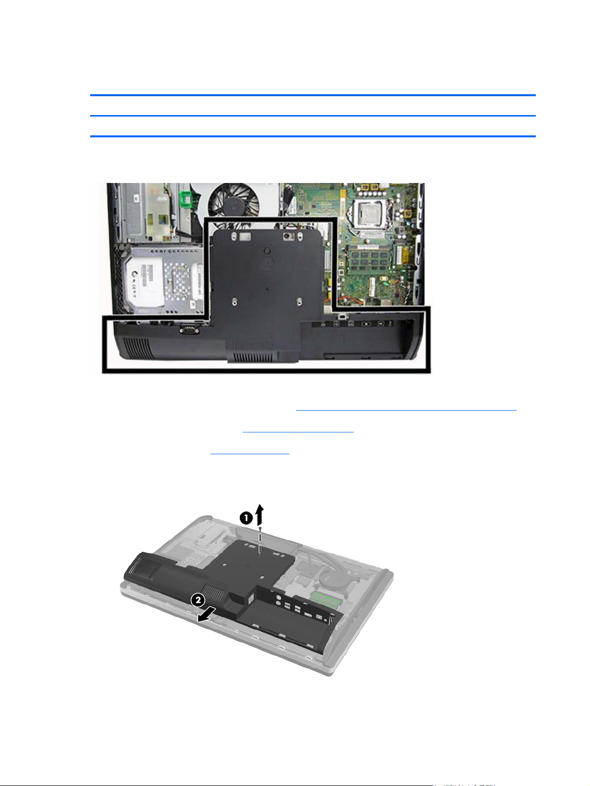
Lower panel
Description Spare part number
Lower rear access panel 762611-001
The lower panel is located under the stand and on the bottom part of the computer.
To remove the access panel:
1. Prepare the computer for disassembly (see
2. Remove the access panel (see
3. Remove the stand (see
4. Remove the screw (1) in the middle of the lower panel, and detach the lower panel from the
chassis (2).
Stand on page 41).
Access panel on page 39).
Preparing to disassemble the computer on page 35).
To replace the lower panel, reverse the removal procedures.
44 Chapter 5 Removal and Replacement Procedures All-in One (AIO) Chassis
Page 55
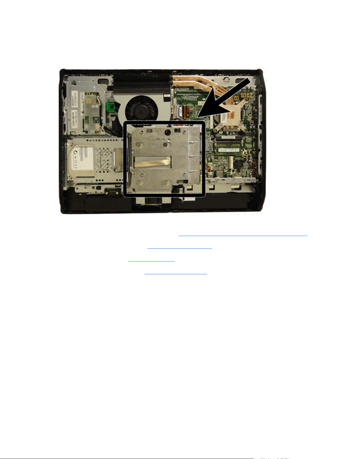
VESA mounting adapter
The VESA mounting adapter is located under the stand.
To remove the VESA mounting adapter:
1. Prepare the computer for disassembly (see
2. Remove the access panel (see
3. Remove the stand (see
4. Remove the lower panel (see
5. Remove the two Torx screws (1) securing the adapter to the chassis.
Stand on page 41).
Access panel on page 39).
Lower panel on page 44).
Preparing to disassemble the computer on page 35).
VESA mounting adapter
45
Page 56

6. Slide the adapter to the left (2), and then lift it off the chassis (3).
To replace the VESA mounting adapter, reverse the removal procedures.
46 Chapter 5 Removal and Replacement Procedures All-in One (AIO) Chassis
Page 57

Drives
Description Spare part number
Optical drives
DVD±RW drive 657958-001
DVD-ROM drive 608394-001
Blu-ray BD-RW SuperMulti XL Drive 719157-001
Removable frame carrier 732060-001
Hard drives
2 TB, 7200 rpm hard drive 616608-001
1 TB, 7200 rpm hard drive 667719-001
1 TB, 7200 rpm hard drive, 2.5-inch, hybrid SSD 724937-001
500 GB, 7200 rpm, hard drive, 3.5-inch 613208-001
500 GB, 7200 rpm, 2.5-inch hard drive, self-encrypting (SED) 696442-001
500 GB, 7200 rpm hard drive, 2.5-inch, hybrid SSD 724938-001
500 GB, 7200 rpm, hard drive, 2.5-inch
500 GB, 7200 rpm, hard drive, 2.5-inch, SED 762188-001
500 GB, 5400 rpm, hard drive, 2.5-inch, FIPS 748317-001
320 GB, 7200 rpm hard drive 761770-001
256 GB Solid State Drive (SSD) 680020-001
256 GB Solid State Drive (SSD), self-encrypting (SED) 746141-001
180 GB Solid State Drive (SSD), MLC 754076-001
128 GB Solid State Drive (SSD) 665961-001
128-GB Solid-State Drive, self-encrypting (SED) 746140-001
120 GB Solid State Drive (SSD) 661841-001
120 GB Solid State Drive (SSD), MLC 756459-001
Grommet, hard drive 594220-001
Replacing a hard disc drive
The hard disc drive is located behind the access panel on the lower left side of the computer (when
viewed from behind). The drive is housed in a removable cage.
761771-001
Drives
47
Page 58

Any one of the following may be installed in the computer:
One 3.5-inch hard disc drive
●
One 2.5-inch solid state drive (SSD) or self-encrypting drive (SED)
●
Two 2.5-inch solid state drives or self-encrypting drives
●
NOTE: Replacing a 3.5-inch drive with a 2.5-inch drive is not supported.
Removing a hard disc drive
●
Installing a hard disc drive
●
Removing a hard disc drive
Removing a 3.5-inch hard disc drive
●
Removing a 2.5-inch hard disc drive
●
Removing a 3.5-inch hard disc drive
1. Prepare the computer for disassembly (see Preparing to disassemble the computer on page 35).
2. Remove the access panel (see
3. Pull the latch next to the lower side of the drive cage away from the cage to release it, then slide
the cage toward the edge of the chassis and lift it out.
Access panel on page 39).
48 Chapter 5 Removal and Replacement Procedures All-in One (AIO) Chassis
Page 59

4. Lift the latch on one side of the drive cage and pull the hard disc drive out of the cage.
5. Remove the four mounting screws from the 3.5-inch hard disc drive. Be sure to keep the screws
together with the blue rubber grommets to use to install a replacement disc drive.
For instructions on installing a hard disc drive, see Installing a hard disc drive on page 52.
Removing a 2.5-inch hard disc drive
1. Prepare the computer for disassembly (see
2. Remove the access panel (see
Preparing to disassemble the computer on page 35).
Access panel on page 39).
Drives
49
Page 60

3. Pull the latch next to the lower side of the drive cage away from the cage to release it, then slide
the cage toward the edge of the chassis and lift it out.
4. If there is a second disc drive in the 2.5-inch drive adapter, disconnect the cable from it.
5. Slide the drive adapter holding the 2.5-inch drive or drives out of the drive cage.
50 Chapter 5 Removal and Replacement Procedures All-in One (AIO) Chassis
Page 61

6. Remove the four mounting screws from the 2.5-inch hard disc drive adapter. Be sure to keep the
screws together with the blue rubber grommets to use to install a replacement drive.
NOTE: The primary drive is the lower position in the drive cage. If only one drive is to be
installed, it must occupy this position.
7. Remove the 2.5-inch hard disc drive(s) from the 2.5-inch drive adapter.
For instructions on installing a hard disc drive, see
Installing a hard disc drive on page 52.
Drives
51
Page 62

Installing a hard disc drive
Installing a 3.5-inch hard disc drive
●
Installing 2.5-inch hard disc drives
●
Installing a 3.5-inch hard disc drive
1. Screw the four mounting screws into the 3.5-inch hard disc drive. Be sure to keep the blue rubber
grommets behind each screw.
2. With the 3.5-inch hard disc drive connectors facing toward the center of the chassis, place the
hard disc drive cage into the chassis and slide it toward the center until it snaps into place.
52 Chapter 5 Removal and Replacement Procedures All-in One (AIO) Chassis
Page 63

3. With the 3.5-inch hard disc drive connector facing toward the center of the chassis, place the
hard disc drive cage into the chassis and slide it toward the center until it snaps into place.
4. Replace the access panel.
5. Reconnect the power cord and external devices.
6. Lock any security devices that were disengaged when the access panel was removed.
Drives
53
Page 64

Installing 2.5-inch hard disc drives
1. Insert the 2.5-inch hard disc drive or drives into the 2.5-inch disc drive adapter. Be sure that the
connectors are at the opening of the adapter.
NOTE: The primary drive is the lower position in the drive adapter. If only one drive is to be
installed, it must occupy this position.
2. Fasten the four mounting screws with grommets into the sides of the 2.5-inch drive adapter.
54 Chapter 5 Removal and Replacement Procedures All-in One (AIO) Chassis
Page 65

3. Slide the drive adapter holding the 2.5-inch drive or drives into the drive cage.
4. Position the drive cage above its final site with the hard disc drive connectors facing toward the
center of the chassis. If the drive cage contains a secondary (upper) drive, connect the SATA cable
to the right of the drive cage to the secondary drive.
Drives
55
Page 66

5. Place the drive cage into the chassis and slide it toward the center until it snaps into place.
6. Replace the access panel.
7. Reconnect the power cord and external devices.
8. Lock any security devices that were disengaged when the access panel was removed.
Replacing the optical disc drive
The optical disc drive is located above the hard disc drive on the left side of the computer (when
viewed from behind).
The optical drive data cable connects to the SATA3 and SATA PWR3 system board connectors.
NOTE: The drive bracket is not spared. When replacing an optical drive, remove the bracket from
the old drive and install it on the new drive.
56 Chapter 5 Removal and Replacement Procedures All-in One (AIO) Chassis
Page 67

1. Prepare the computer for disassembly (see Preparing to disassemble the computer on page 35).
2. Remove the access panel (see
Access panel on page 39).
3. Lift the tab at the back of the optical disc drive enclosure to release the drive.
NOTE: When replacing an optical drive, remove the bracket from the old drive and install it on
the new drive. The bracket is not spared.
Drives
57
Page 68

4. Remove the two screws securing the optical disc drive bracket to the drive.
In install the drive, reverse the removal procedures.
NOTE: The optical disc drive can be installed in only one way.
58 Chapter 5 Removal and Replacement Procedures All-in One (AIO) Chassis
Page 69

Memory
Description Spare part number
8-GB 689374-001
4-GB 689373-001
2-GB 689372-001
Memory modules are located on the right side of the computer (viewed from behind).
The computer has two memory slots that can be populated with up to two industry-standard SODIMMs.
These memory sockets are populated with at least one preinstalled SODIMM. To achieve the maximum
memory support, you can populate the system board with up to 16 GB of memory.
For proper system operation, the SODIMMs must be:
industry-standard 204-pin
●
unbuffered non-ECC PC3-10600 DDR3-1600 MHz-compliant
●
1.5 volt DDR3-SDRAM SODIMMs
●
The DDR3-SDRAM SODIMMs must also:
support CAS latency 11 DDR3 1600 MHz (11-11-11 timing)
●
contain the mandatory Joint Electronic Device Engineering Council (JEDEC) specification
●
Memory
59
Page 70

In addition, the computer supports:
1-Gbit, 2-Gbit, and 4-Gbit non-ECC memory technologies
●
single-sided and double-sided SODIMMS
●
SODIMMs constructed with x8 and x16 SDRAMs; SODIMMs constructed with x4 SDRAMs are not
●
supported
NOTE: The system will not operate properly if you install unsupported SODIMM memory.
The system will automatically operate in single channel mode, dual channel mode, or flex mode,
depending on how the SODIMMs are installed. Refer to the following table to identify the SODIMM
channel locations.
Location System Board Label Channel
Lower Socket SODIMM1 Channel A
Upper Socket SODIMM3 Channel B
The system will operate in single channel mode if the SODIMM sockets are populated in one
●
channel only.
The system will operate in flex mode if the memory capacity of the SODIMM in Channel A is not
●
equal to the memory capacity of the SODIMM in Channel B. In flex mode, the channel populated
with the least amount of memory describes the total amount of memory assigned to dual channel
and the remainder is assigned to single channel. If one channel will have more memory than the
other, the larger amount should be assigned to channel A.
The system will operate in a higher-performing dual channel mode if the memory capacity of the
●
SODIMM in Channel A is equal to the memory capacity of the SODIMM in Channel B.
In any mode, the maximum operational speed is determined by the slowest SODIMM in the
●
system.
There are two memory sockets on the system board located behind the memory access panel. To
remove or install memory modules:
To remove a memory module:
1. Prepare the computer for disassembly (see
Preparing to disassemble the computer on page 35).
2. Place the computer face down on a soft flat surface. HP recommends that you set down a blanket,
towel, or other soft cloth to protect the screen surface from scratches or other damage.
3. Remove the access panel (see
Access panel on page 39).
60 Chapter 5 Removal and Replacement Procedures All-in One (AIO) Chassis
Page 71

4. To remove a memory module, press outward on the two latches on each side of the SODIMM (1),
then pull the SODIMM out of the socket (2).
5. To install a memory module, slide the SODIMM into the socket at approximately a 30° angle (1),
then press the SODIMM down (2) so that the latches lock it in place.
NOTE: A memory module can be installed in only one way. Match the notch on the module with
the tab on the memory socket.
The computer automatically recognizes the additional memory when you turn on the computer.
Memory
61
Page 72

Battery
The RTC battery is located to the lower right of the fan.
The battery is located in the memory compartment. The battery that comes with the computer provides
power to the real-time clock. When replacing the battery, use a battery equivalent to the battery
originally installed in the computer. The computer comes with a 3-volt lithium coin cell battery.
WARNING! The computer contains an internal lithium manganese dioxide battery. There is a risk of
fire and burns if the battery is not handled properly. To reduce the risk of personal injury:
Do not attempt to recharge the battery.
Do not expose to temperatures higher than 60° C (140º F).
Do not disassemble, crush, puncture, short external contacts, or dispose of in fire or water.
Replace the battery only with the HP spare designated for this product.
CAUTION: Before replacing the battery, it is important to back up the computer CMOS settings.
When the battery is removed or replaced, the CMOS settings will be cleared.
Static electricity can damage the electronic components of the computer or optional equipment. Before
beginning these procedures, ensure that you are discharged of static electricity by briefly touching a
grounded metal object.
62 Chapter 5 Removal and Replacement Procedures All-in One (AIO) Chassis
Page 73

NOTE: The lifetime of the lithium battery can be extended by plugging the computer into a live AC
wall socket. The lithium battery is only used when the computer is NOT connected to AC power.
HP encourages customers to recycle used electronic hardware, HP original print cartridges, and
rechargeable batteries. For more information about recycling programs, go to
http://www.hp.com/
recycle.
1. Prepare the computer for disassembly (see Preparing to disassemble the computer on page 35).
2. Remove the access panel (see
Access panel on page 39).
The battery can now be seen on the lower right side of the fan.
3. To release the battery from its holder, squeeze the metal clamp that extends above one edge of
the battery. When the battery pops up, lift it out (1).
4. To insert the new battery, slide one edge of the replacement battery under the holder’s lip with the
positive side up. Push the other edge down until the clamp snaps over the other edge of the
battery (2).
Battery
63
Page 74

Serial port
Description Spare part number
Serial port 698212-001
The serial port is located near the bottom of the computer below the hard drive. It is secured with one
Phillips screw.
To remove the serial port:
1. Prepare the computer for disassembly (see
2. Remove the access panel (see
3. Remove the lower panel (see
4. Remove the Phillips screw (1) that secures the port to the computer.
5. Slide the bottom of the port assembly to remove it from the tab in the computer (2).
Access panel on page 39).
Lower panel on page 44).
Preparing to disassemble the computer on page 35).
64 Chapter 5 Removal and Replacement Procedures All-in One (AIO) Chassis
Page 75

6. Remove the cable from its routing path (3), and remove the serial port assembly from the
computer.
To install the serial port, reverse the removal procedures.
Serial port
65
Page 76

Webcam module
Description Spare part number
Webcam module 732510-001
On products that ship with a webcam module, the module is located at the top of the computer beneath
the top panel. It is secured with two silver Phillips screws and has one connector.
The webcam module is optional.
To remove the webcam module:
1. Prepare the computer for disassembly (see
2. Remove the access panel (see
66 Chapter 5 Removal and Replacement Procedures All-in One (AIO) Chassis
Access panel on page 39).
Preparing to disassemble the computer on page 35).
Page 77
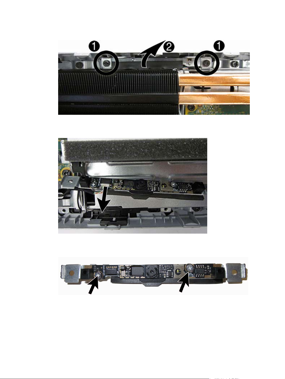
3. Remove the two Torx screws that secure the webcam module bracket to the computer.
4. Rotate the assembly to gain access to the connector on the module, and then disconnect the cable
from the module.
5. To remove the module from the bracket, remove the two Phillips screws that secure the module,
and then separate the module from the bracket.
To install a webcam module, reverse the removal procedures.
Webcam module
67
Page 78
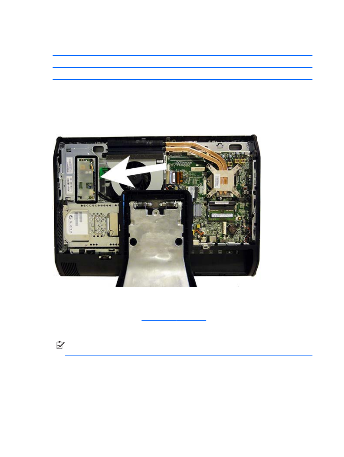
Converter board
Description Spare part number
Converter board 752122-001
The converter board is located on the left side of the computer (viewed from behind) under the main
rear cover. It is secured with two Torx screws and has two connectors.
Use the same converter spare part for all display panels; however, you must change jumper settings on
the board based on the display panel.
To remove the converter board:
1. Prepare the computer for disassembly (see
2. Remove the access panel (see
3. Disconnect the two cables from the board (1).
NOTE: Be careful not to damage the cables when disconnecting them from the board. Do not
pull on the wires.
68 Chapter 5 Removal and Replacement Procedures All-in One (AIO) Chassis
Access panel on page 39).
Preparing to disassemble the computer on page 35).
Page 79

4. Remove the two black Torx screws (2) that secure the board to the computer.
Note the converter board jumper settings labeled on the chassis (3). Be sure to correctly position
the jumpers on the converter board for the installed display panel.
5. Lift the converter board from the computer.
To install the converter board, reverse the removal procedures.
Converter board
69
Page 80

Heat sink
Description Spare part number
Heat sink 698201-001
The heat sink is secured with five Torx screws – four captured, one not captured.
To remove the heat sink:
1. Prepare the computer for disassembly (see
2. Remove the access panel (see
Access panel on page 39).
Preparing to disassemble the computer on page 35).
70 Chapter 5 Removal and Replacement Procedures All-in One (AIO) Chassis
Page 81

3. In the order indicated on the heat sink, loosen the four silver captive Torx screws (1) – (4), and
then lift the heat sink out of the computer (5).
CAUTION: Remove heat sink retaining screws in diagonally opposite pairs (as in an X) to even
the downward forces on the processor. This is especially important as the pins on the socket are
very fragile and any damage to them may require replacing the system board.
CAUTION: To reduce a degradation in thermal performance, be sure not to touch the thermal
grease on the surface of the processor or the heat sink.
To replace the heat sink, reverse the removal procedures.
Heat sink
71
Page 82

Processor
Description Spare part number
Intel Core i7-4790s (3.2-GHz, 8-MB L3 cache) 773554-001
Intel Core i7-4770s (3.1-GHz, 8-MB L3 cache) 732507-001
Intel Core i5-4690s (3.2-GHz, 6-MB L3 cache) 773083-001
Intel Core i5-4670s (3.1-GHz, 6-MB L3 cache) 732506-001
Intel Core i5-4590s (3.0-GHz, 6-MB L3 cache) 773082-001
Intel Core i5-4570s (2.9-GHz, 6-MB L3 cache) 732505-001
Intel Core i3-4360 (3.7-GHz, 4-MB L3 cache) 769735-001
Intel Core i3-4350 (3.6-GHz, 4-MB L3 cache) 769734-001
Intel Core i3-4340 (3.6-GHz, 4-MB L3 cache) 742562-001
Intel Core i3-4330 (3.5-GHz, 4-MB L3 cache) 742561-001
Intel Core i3-4150 (3.5-GHz, 3-MB L3 cache) 769733-001
Intel Core i3-4130 (3.4-GHz, 3-MB L3 cache) 742560-001
Intel Pentium G3450 (3.4-GHz, 3-MB L3 cache) 769741-001
Intel Pentium G3440 (3.3-GHz, 3-MB L3 cache) 769740-001
Intel Pentium G3430 (3.3-GHz, 3-MB L3 cache) 742566-001
Intel Pentium G3420 (3.2-GHz, 3-MB L3 cache) 742565-001
Intel Pentium G3240 (3.1-GHz, 3-MB L3 cache) 769739-001
Intel Pentium G3220 (3.0-GHz, 3-MB L3 cache) 742564-001
Intel Celeron G1850 (2.9-GHz, 2-MB L3 cache) 769732-001
Intel Celeron G1840 (2.8-GHz, 2-MB L3 cache) 769731-001
Intel Celeron G1830 (2.8-GHz, 2-MB L3 cache) 758757-001
Intel Celeron G1820 (2.7-GHz, 2-MB L3 cache) 758756-001
1. Prepare the computer for disassembly (see Preparing to disassemble the computer on page 35).
2. Remove the access panel (see
3. Remove the heat sink (see
Access panel on page 39).
Heat sink on page 70).
4. Rotate the locking lever to its full open position (1).
5. Raise and rotate the microprocessor retainer to its fully open position (2).
72 Chapter 5 Removal and Replacement Procedures All-in One (AIO) Chassis
Page 83

6. Carefully lift the processor from the socket (3).
CAUTION: Do NOT handle the pins in the processor socket. These pins are very fragile and
handling them could cause irreparable damage. Once pins are damaged it may be necessary to
replace the system board.
The heat sink must be installed within 24 hours of installing the processor to prevent damage to
the processor’s solder connections.
To install a new processor:
1. Place the processor in its socket and close the retainer. Make sure the slot in the processor fits into
the post on the socket.
2. Secure the locking lever. If reusing the existing heat sink, go to step 3. If using a new heat sink, go
to step 6.
3. If reusing the existing fan sink, clean the bottom of the fan sink with the alcohol pad provided in
the spares kit.
CAUTION: Before reinstalling the fan sink you must clean the top of the processor and the
bottom of the fan sink with an alcohol pad supplied in the spares kit. After the alcohol has
evaporated, apply thermal grease to the top of the processor from the syringe supplied in the
spares kit.
4. Apply the thermal grease provided in the spares kit to the top of the processor and install the fan
sink atop the processor.
5. Go to step 7.
Processor
73
Page 84

6. If using a new fan sink, remove the protective covering from the bottom of the fan sink and place it
in position atop the processor.
7. Secure the fan sink to the system board and system board tray.
CAUTION: Fan sink retaining screws should be tightened in diagonally opposite pairs (as in an
X) to evenly seat the fan sink on the processor. This is especially important as the pins on the
socket are very fragile and any damage to them may require replacing the system board.
NOTE: After installing a new processor onto the system board, always update the system ROM to
ensure that the latest version of the BIOS is being used on the computer. The latest system BIOS can be
found on the Web at:
http://h18000.www.hp.com/support.
74 Chapter 5 Removal and Replacement Procedures All-in One (AIO) Chassis
Page 85

mSATA Solid-State Drive
Description Spare part number
32-GB mSATA drive 762612-001
32-GB mSATA drive, SRT 762613-001
The mSATA SSD is located on the bottom of the system board. The drive is secured with two Phillips
screws.
NOTE: In the following image, the mSATA SSD is not shown.
To remove the mSATA SSD:
1. Prepare the computer for disassembly (see
2. Remove the access panel (see
3. Remove the two Phillips screws that secure the SSD to the computer.
Access panel on page 39).
Preparing to disassemble the computer on page 35).
mSATA Solid-State Drive
75
Page 86

4. Lift the SSD to a 45-degree angle, and then pull it away to remove it from the socket.
To install the mSATA SSD, reverse the removal procedures.
NOTE: mSATA SSD are designed with a notch to prevent incorrect insertion.
76 Chapter 5 Removal and Replacement Procedures All-in One (AIO) Chassis
Page 87

WLAN module
Description Spare part number
HP WLAN 802.11 a/g/n, 2x2 701398-001
Intel Dual Band Wireless-N 7260NB 802.11 a/b/g/n 2x2 WiFi 717382-001
HP WLAN 802.11 a/b/g/n + Bluetooth 4.0 697316-001
The WLAN module is located on the left side of the system board. The module is secured with one
Phillips screw and has two connected antennas.
NOTE: The procedure to replace the WLAN module must be performed by an HP technician.
NOTE: WLAN module appearance may vary.
To remove the WLAN module:
1. Prepare the computer for disassembly (see
2. Remove the access panel (see
3. Remove the stand (see
Stand on page 41).
4. Remove the lower panel (see
Access panel on page 39).
Lower panel on page 44).
5. Remove the VESA mounting adapter (see
Preparing to disassemble the computer on page 35).
VESA mounting adapter on page 45).
6. Disconnect the antenna cables from the module (1).
7. Remove the screw (2) that secures the module to the computer.
WLAN module
77
Page 88

8. Lift the module to a 45-degree angle, and then pull it away to remove it from the socket (3).
To install the WLAN module, reverse the removal procedures.
NOTE: WLAN modules are designed with a notch to prevent incorrect insertion.
78 Chapter 5 Removal and Replacement Procedures All-in One (AIO) Chassis
Page 89

Speakers
Description Spare part number
Speakers 698197-001
On products that ship with speakers, the speakers are located at the bottom of the computer. Two
separate speakers are each secured by two Torx screws. To remove the right speaker you have to
remove the power supply plug.
Speakers are optional.
To remove the speakers:
1. Prepare the computer for disassembly (see
2. Remove the access panel (see
3. Remove the stand (see
4. Remove the lower panel (see
5. Remove Torx screw that secures the power connector to the computer, and lift the connector from
its position on top of the left speaker (1).
6. Remove two Torx screws (2) that secure each speaker to the computer.
7. Disconnect the speaker cables from the system board connector labeled SPKR (3).
Stand on page 41).
Access panel on page 39).
Lower panel on page 44).
Preparing to disassemble the computer on page 35).
8. Remove the speakers from the computer.
To install the speakers, reverse the removal procedures.
Speakers
79
Page 90

Fan
Description Spare part number
Fan 698196-001
The fan is located near the middle of the computer and is secured with three Torx screws. You have to
remove the VESA mounting adapter to remove the fan.
To remove the fan assembly:
1. Prepare the computer for disassembly (see
2. Remove the access panel (see
3. Remove the stand (see
4. Remove the lower panel (see
5. Remove the VESA mounting adapter (see
6. Disconnect the fan cable from the system board connector labeled CHFAN (1).
7. Remove the three Torx screws that secure the fan to the computer (2).
Stand on page 41).
Access panel on page 39).
Lower panel on page 44).
Preparing to disassemble the computer on page 35).
VESA mounting adapter on page 45).
80 Chapter 5 Removal and Replacement Procedures All-in One (AIO) Chassis
Page 91

8. Remove the fan from the computer (3).
To install the fan assembly, reverse the removal procedures.
NOTE: To avoid damaging the rubber screw grommets installed around the captive screws, when
installing the fan, push down on the fan assembly before you tighten the screws. Make sure the
grommets are positioned correctly before tightening the screws.
Fan
81
Page 92

Side panels
Description Spare part number
Left side panel 732489-001
Right side panel 698193-001
The side panels are located one each side of the computer. They are secured with tabs, and the
removal procedures are similar for both panels.
To remove the side panels:
1. Prepare the computer for disassembly (see
2. Remove the access panel (see
3. Remove the stand (see
4. Remove the lower panel (see
5. Remove the optical drive (see
6. Push the side panel out from the bottom (1).
82 Chapter 5 Removal and Replacement Procedures All-in One (AIO) Chassis
Stand on page 41).
Access panel on page 39).
Lower panel on page 44).
Replacing the optical disc drive on page 56).
Preparing to disassemble the computer on page 35).
Page 93

7. Rotate the panel out and off of the computer (2).
NOTE: The removal and replacement procedures are similar for both panels.
To install the side panels, reverse the removal procedures.
Side panels
83
Page 94

Power supply
Description Spare part number
Power supply, 180-W 732494-001
The power supply is located at the middle, bottom of the computer. It is secured with two Torx screws.
The power connector mounts separately with one Torx screw. The power supply slides out of the bottom
of the bracket that secures it.
To remove the power supply:
1. Prepare the computer for disassembly (see
2. Remove the access panel (see
3. Remove the stand (see
4. Remove the lower panel (see
84 Chapter 5 Removal and Replacement Procedures All-in One (AIO) Chassis
Stand on page 41).
Access panel on page 39).
Lower panel on page 44).
Preparing to disassemble the computer on page 35).
Page 95

5. Remove the two Torx screws (1) that secure the power connector to the computer, and then lift the
connector from atop the speaker (2).
6. Disconnect the cable from the system board connector (1).
7. Position the cable above the power supply (2).
Positioning the cable above the power supply makes it easier to slide the power supply downward
and out of the bracket that secures it.
Power supply
85
Page 96

8. Slide the power supply downward and out of the bracket that houses it.
To install the power supply, reverse the removal procedures.
86 Chapter 5 Removal and Replacement Procedures All-in One (AIO) Chassis
Page 97

System board
Description Spare part number
System board for use in models without Windows 8 758190-001
System board for use in models with Windows 8 Standard 758190-501
System board for use in models with Windows 8 Professional 758190-601
The system board is located on the right side of the computer (viewed from the rear). It is secured with
eight Torx screws.
To remove the system board:
1. Prepare the computer for disassembly (see
2. Remove the access panel (see
3. Remove the stand (see
Stand on page 41).
4. Remove the lower panel (see
5. Remove the memory modules (see
6. Remove the heat sink (see
7. Remove the processor (see
8. Remove the WLAN module (see
Access panel on page 39).
Lower panel on page 44).
Memory on page 59).
Heat sink on page 70).
Processor on page 72).
WLAN module on page 77).
Preparing to disassemble the computer on page 35).
9. Disconnect all cables from the system board, noting their location for reinstallation.
System board
87
Page 98

10. Remove the cable mounting bracket by removing the Torx screw (1), and then sliding it up (2)
and lifting it out of the computer.
88 Chapter 5 Removal and Replacement Procedures All-in One (AIO) Chassis
Page 99

11. Remove the three Torx screws that secure the outer side bracket to the computer. The screws also
secure the system board.
System board
89
Page 100

12. Rotate the side bracket up and off the computer.
13. Remove the eight remaining Torx screws that secure the system board to the computer.
90 Chapter 5 Removal and Replacement Procedures All-in One (AIO) Chassis
 Loading...