

Page 1
appendix
C
ONNECTOR PIN ASSIGNMENTS
This appendix contains the pin assignments for all external connectors:
Connector and Icon (Orange) Pin Signal
65
43
KEY
1
2
Connector and Icon (Green) Pin Signal
65
43
KEY
1
2
A
Table A-1
Enhanced Keyboard
1
2
3
4
5
6
Data
Unused
Ground
+5 VDC
Clock
Unused
Table A-2
Mouse
1
2
3
4
5
6
Data
Unused
Ground
+5 VDC
Clock
Unused
Compaq Deskpro 4000 and 6000 Series of Personal Computers A-1
Page 2
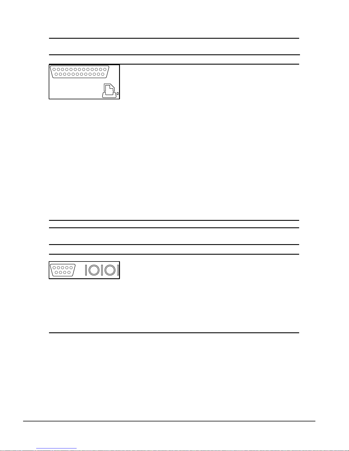
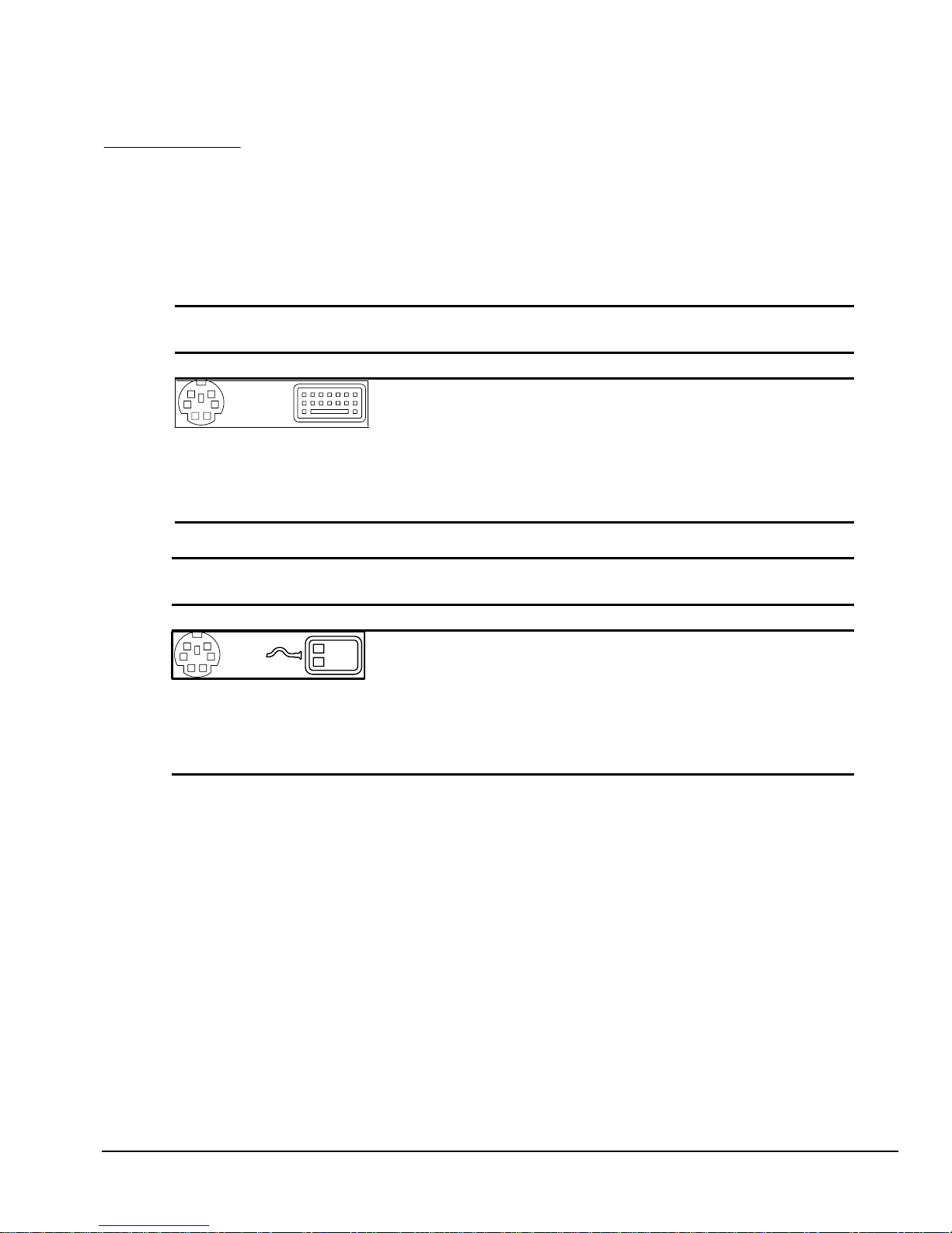
Table A-3
Parallel Interface
Connector and Icon Pin Signal
910111213 8 7 6 5
22232425
20 19 1821 17 141516
2341
1
2
3
4
5
6
7
8
9
10
11
12
13
14
15
16
17
18-25
Strobe
Data Bit 0
Data Bit 1
Data Bit 2
Data Bit 3
Data Bit 4
Data Bit 5
Data Bit 6
Data Bit 7
Acknowledge
Busy
Paper End
Select
Auto Linefeed
Error
Initialize Printer
Select IN
Signal Ground
Table A-4
Serial Interfaces
Connector and Icon Pin Signal
12345
6789
1
2
3
4
5
6
7
8
9
Carrier Detect
Receive Data
Transmit Data
Data Terminal Ready
Signal Ground
Data Set Ready
Request to Send
Clear to Send
Ring Indicator
A-2 Connector Pin Assignments
Page 3
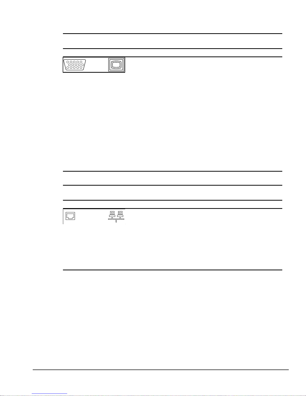
Table A-5
Monitor
Connector Pin Signal
12345
78
KEY
10
15 14 13 12 11
6
* For DDC support (I2C monitors)
1
2
3
4
5
6
7
8
9
10
11
12
13
14
15
Red Analog
Green Analog
Blue Analog
Monitor ID Bit2
Ground
Ground Analog
Ground Analog
Ground Analog
Not Connected
Ground
Monitor ID Bit 0
Bi-directional Data (SDA)*
Horizontal Sync
Vertical Sync
Data Clock (SCL)*
Table A-6
Ethernet RJ-45
Connector and Icon Pin Signal
1
2
3
4
5
6
7
8
(+) Transmit Data
(-) Transmit Data
(+) Receive Data
Unused
Unused
(-) Receive Data
Unused
Unused
Compaq Deskpro 4000 and 6000 Series of Personal Computers A-3
Page 4

Table A-7
Ultra SCSI
Connector and Icon Pin Signal
1-11
12
13
14
15-25
26
27
28
29
30
31
32
33
34
35
36
37
38
39
40
41
42
43
44
45
46
47
48
49
50
Ground
Reserved
Open
Reserved
Ground
DBO
DB1
DB2
DB3
DB4
DB5
DB6
DB7
DBP
Ground
Ground
Reserved
TERMPWR
Reserved
Ground
ATN #
Ground
BSY #
ACK #
RST #
MSG #
SEL #
C/D
REQ #
Input/Output
A-4 Connector Pin Assignments
Page 5
Connector and Icon
Connector and Icon
Connector and Icon (Blue)
Table A-8
Line-Out Audio Connector
1/8-inch Miniphone
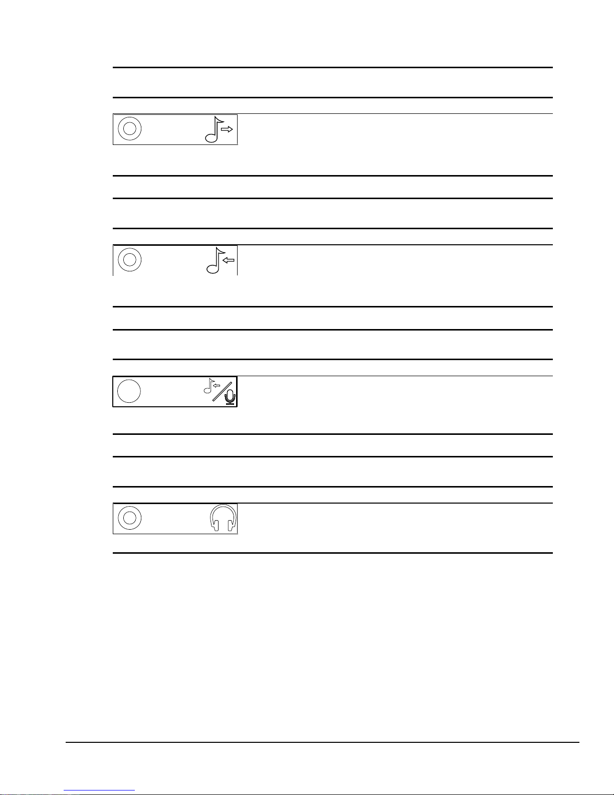
Table A-9
Line-In Audio Connector
1/8-inch Miniphone
Table A-10
Microphone Connector
Stereo 1/8-inch Miniphone
Connector and Icon
Table A-11
Headphone Connector
Stereo 1/8-inch Miniphone
Compaq Deskpro 4000 and 6000 Series of Personal Computers A-5
Page 6

Table A-12
USB Connector
Connector and Icon Pin Signal
1234
1
2
3
4
VCC
- Data
+ Data
Ground
A-6 Connector Pin Assignments
Page 7

Table A-13
External Infrared Transceiver
Connector and Icon Pin Signal
65
43
KEY
1
2
1
2
3
4
5
6
7
8
Transmit
Receive
Ground
5V
Mode
Not Used
Not Used
Not used
Table A-14
Ethernet AUI
Connector and Icon Pin Signal
7
15 14
5643
13 12 11 1089
12
1
2
3
4
5
6
7
8
9
10
11
12
13
14
15
Ground
(+) Collision Detect
(+) Transmit Data
Ground
(+) Receive Data
Ground
Not Used
Ground
(-) Collision Detect
(-) Transmit Data
Ground
(-) Receive Data
+12V Supply
Ground
Not Used
Compaq Deskpro 4000 and 6000 Series of Personal Computers A-7
Page 8

appendix
OWER CORD SET
P
EQUIREMENTS
R
The voltage select switch feature on the computer permits it to operate from any line voltage between
100-120 or 200-240 volts AC.
The power cord set received with the computer meets the requirements for use in the country where
you purchased the equipment.
Power cord sets for use in other countries must meet the requirements of the country where you use
the computer. For more information on power cord set requirements, contact your authorized
Compaq dealer, reseller or service provider.
General Requirements
The requirements listed below are applicable to all countries:
1. The length of the power cord set must be at least 6.00 feet (1.8 m) and a maximum of 9.75 feet
(3.0 m).
B
2. All power cord sets must be approved by an acceptable accredited agency responsible for
evaluation in the country where the power cord set will be used.
3. The power cord set must have a minimum current capacity of 10A and a nominal voltage rating
of 125 or 250 volts AC, as required by each country’s power system.
4. The appliance coupler must meet the mechanical configuration of an EN 60 320/IEC 320
Standard Sheet C13 connector, for mating with appliance inlet on the Switch Box.
Compaq Deskpro 4000 and 6000 Series of Personal Computers
B-1
B
Page 9

Country-Specific Requirements
Power Cord Set Requirements–By Country
Country Accrediting Agency Applicable Note Numbers
Australia EANSW 1
Austria OVE 1
Belgium CEBC 1
Canada CSA 2
Denmark DEMKO 1
Finland SETI 1
France UTE 1
Germany VDE 1
Italy IMQ 1
Japan JIS 3
Norway NEMKO 1
Sweden SEMKO 1
Switzerland SEV 1
United Kingdom BSI 1
United States UL 2
NOTES:
1. The flexible cord must be <HAR> Type HO5VV-F, 3-conductor, 1.0 mm2 conductor size. Power
cord set fittings (appliance coupler and wall plug) must bear the certification mark of the agency
responsible for evaluation in the country where it will be used.
2. The flexible cord must be Type SJT or equivalent, No. 18 AWG, 3-conductor. The wall plug
must be a two-pole grounding type with a NEMA 5-15P (15A, 125V) or NEMA 6-15P (15A
250V) configuration.
3. The appliance coupler, flexible cord, and wall plug must bear a "T" mark and registration number
in accordance with the Japanese Dentori Law. The flexible cord must be Type VCT or VCTF,
3-conductor, 0.75 mm2 conductor size. The wall plug must be a two-pole grounding type with a
Japanese Industrial Standard C8303 (15A, 125V) configuration.
B-2
Power Cord Set Requirements
Page 10

appendix
H
ARD DRIVES
Compaq Computer Corporation uses IDE hard disk drives that conform to two different
primary/secondary implementations. These are Conner mode and ATA-compatible mode. These two
modes are incompatible with one another.
If installing a second Ultra ATA hard drive on the primary controller, you must use an 80-conductor
ATA cable for optimal performance.
Device 0/Device 1 Relationship
A device 0/device 1 relationship exists when there are two hard drives connected to a single port. In
this situation, one drive must be designated as the device 0, or primary drive and the other as the
device 1, or secondary drive. This designation is necessary because both drives cannot work
simultaneously.
Cable Select
C
The Compaq Deskpro 4000 Series of Personal Computers use cable-select technology for identifying
Device 0 (primary) and Device 1 (secondary) IDE hard drives. Check that the jumpers on the IDE
hard drives are set properly for cable-select installation. Always check the label on the drives or
check Chapter 7 of this manual when a new drive is added to verify that the jumper settings are set
correctly.
Cable select may not function properly if drives other than those supported by Compaq are
installed.
The second drive on a cable-select cable can be a CD-ROM drive. However, the CD-ROM drive
must be installed in the device 1 position if a hard drive is installed on the same cable. Ensure
that both drives are set for cable-select configuration. See Chapter 7 for more information.
If two drives are already connected to the primary IDE controller and an additional drive is to be
installed, the secondary IDE controller must be enabled. The secondary IDE controller can be
enabled by checking this option after opening the Advanced box in the Mass Storage group of
F10 Computer Setup. See Chapter 8 for more information.
When more than two drives are installed, drive performances are best when the two faster drives
are connected to the primary IDE controller and the slower drive is connected to the secondary
IDE controller.
Compaq Deskpro 4000 and 6000 Series of Personal Computers C-1
Page 11

A hard drive is installed and configured more quickly when it has first been formatted.
If the new drive includes the cable select feature, no jumper setting changes are required. Refer to
the documentation supplied with the drive for instructions on using the cable select feature. If
you install a third-party hard drive, you will need to purchase a jumper cable (spare part number
247568-001) from Compaq Computer Corporation.
SMART
The SMART IDE hard drives for the Compaq Deskpro 4000 Series of Personal Computers have
built-in drive failure prediction that warns the user or the network administrator of an impending
failure or crash of the hard drive.
Automatic Soft-Drive Types
An automatic soft-drive type is a mechanism where the system ROM and Computer Setup provide
support for IDE hard drives that are not supported in the hard drive parameter table. Computer Setup
automatically builds a soft-drive type when it finds that a hard drive is not in the hard drive parameter
table.
The soft-drive types assign according to the table below:
Table 3-1
Soft-Drive Type Assignments
Drive Hard Drive Type Controller
0 65 Primary
1 66 Primary
0 68 Secondary
1 15 Secondary
For hard drives that are greater than 528 MB, the system automatically translates the hard drive
parameter for DOS by logically halving the cylinders and doubling the heads. This allows DOS to
access greater than 528 MB. The translated hard drive parameters are put into the hard drive
parameter table in the shadow RAM copy of the system ROM. When using any operating system
other than DOS, you must use the Compaq User Diagnostic diskette to set up the hard drive
parameter table without translation.
C-2 Hard Drives
Page 12

appendix
D
SCSI G
This appendix contains helpful guidelines for installing Small Computer System
Interface (SCSI) devices.
UIDELINES
Guidelines for Installing Optional
SCSI Devices
When installing and operating SCSI devices, you must adhere to the following
guidelines:
■
A single SCSI controller allows you to daisy-chain up to seven SCSI devices. These may be hard
drives, CD-ROM drives, scanners, tape drives, and/or other SCSI devices installed in your
computer. Most SCSI controllers have connectors for both internal and external devices.
Every SCSI device must have a unique identification (ID) number. The SCSI controller
■
identifies signals to and from a SCSI device by its SCSI ID number rather than its location. Moving
a SCSI device from one position to another on the SCSI chain does not affect the communication
between the controller and the SCSI device. Check the information that came with your device for
the recommended SCSI ID number to be applied. The reserved and available SCSI ID numbers for
Compaq computers are as follows:
❏
0 is reserved for the primary hard drive and has the lowest device priority.
❏
1 through 6 are available for use by all SCSI devices.
❏
7 is reserved for the system board and has the highest device priority.
Every SCSI chain or circuit must be terminated (closed) at both ends. Termination can be
■
accomplished in one of several ways:
❏
Use a cable with a built-in terminator.
❏
Use a cable with a terminating resistor plug in the last connector.
❏
Connect a SCSI device, with the termination enabled, into the last connector.
❏
Some systems have both ends of the SCSI cable connected to, and terminated by,
the system board.
Turn on all external SCSI devices before turning on power to the computer. This enables the
■
controller to recognize the external SCSI devices and automatically reset. When an external SCSI
device is connected to the external SCSI connector on the rear panel of the computer, that device
becomes the end of the SCSI chain and must be terminated.
All SCSI hard drives must be either internal or external, but never both. The system does
■
accommodate a combination of other internal and external SCSI devices, such as SCSI tape and
CD-ROM drives.
Compaq Deskpro 4000 and 6000 Series of Personal Computers D-1
Page 13

Termination
1. Every SCSI chain must be terminated at both ends regardless of whether it is an internal SCSI
chain, an external SCSI chain, or a combination internal-external SCSI chain.
2. Compaq SCSI-2 controllers have an automatic terminating device which turns OFF the terminator
when both the external and internal SCSI signal ports connect to SCSI devices.
3. A terminating resistor plug is molded into one end of some internal flat SCSI signal cables. It may
also be a separate electronic device that installs into the SCSI signal port of an external device,
installs into an internal flat SCSI signal cable connector, or installs into the SCSI signal port of
some non-Compaq SCSI-2 controllers.
4. Terminators are generally designated as being active or passive by the voltage limiting method
used. The product documentation usually describes the terminator type.
5. All Compaq SCSI-2 controllers have active terminators. Active terminators more effectively filter
out electronic noise (voltage surges) on the SCSI chain than passive terminators.
6. To ensure the integrity of data transferred faster than 5 megabytes per second, use active
terminators to terminate the SCSI chain.
D-2 SCSI Guidelines
Page 14

appendix
D
UAL INLINE MEMORY MODULE
C
ONFIGURATIONS
This appendix contains helpful guidelines for determining Dual Inline Memory Modules
(DIMMs) limitations.
Intel 440LX Chipset Memory
Limitations
The Intel 440LX Chipset has many functions, one of which is memory support. The Deskpro
4000 and 6000 models with the Intel Pentium II processor come standard in a three DIMM
memory socket configuration. Due to inherent architectural limitations, the Intel 440LX chipset
does not support any DIMM Modules comprised of x4 SDRAM chips and some combinations of
DIMM Modules with x8 and x32 SDRAM chips in the 3-DIMM Socket configuration. The
following describes how to determine whether a DIMM is x4, x8, or x32.
E
SDRAM Chips
Each SDRAM chip is essentially a large table of rows and columns. Each row corresponds to one
address. Each column in the row corresponds to a bit of data. When a row is accessed, it will
output all of the data in its columns for that row onto the data bus. The number of columns for
each SDRAM is either 4, 8, 16, or 32 — referred to as the data width of the SDRAM and is
specified as x4, x8, x16, or x32.
The SDRAM chips that make up a DIMM Module are built using either 16 Mb (mega bit)
memory technology or 64 Mb memory technology. Each chip is capable of storing either 16 x 10
bits of information or 64 x 106 bits of information.
The size of the SDRAM is given by stating the number of rows by the number of columns. When
multiplied together, the number of rows times the number of columns should equal the memory
technology used. An x8 SDRAM built using 16 Mb technology has 2 x 10
of the SDRAM is specified as 2Mx8 bits. If the x8 SDRAM was built using 64 Mb technology,
then there would be 8 x 10
By knowing the width of each SDRAM chip, the total number of chips needed for each DIMM
Module can be determined.
6
rows and the total size of the SDRAM would be specified as 8Mx8.
6
rows. The total size
6
Compaq Deskpro 4000 and 6000 Series of Personal Computers E-1
Page 15

To identify the SDRAM data width, use the total memory of the DIMM Module, the total
number of SDRAM chips and the information Table E-1. By knowing the total size of the DIMM
Module and how many SDRAM chips are on each side of the module, the memory technology
and data width of the SDRAM chips can be determined.
For example, a 32 MB DIMM Module with 8 chips on each side for 16 chips total is most likely
comprised of 16Mb technology SDRAM chips with a data width of x8.
That same 32 MB DIMM Module, but with only 4 chips on one side is most likely comprised of
64Mb technology SDRAM chips with a data width of x16.
E-2 Dual Inline Memory Module Configurations
Page 16

Table 5-1
SDRAM Memory Technologies*
SDRAM
SIZE
# Of
Address
Locations
(# Of
SDRAM
Width (# Of
Data Bits
Per Row)
# Of Chips
Non-ECC
(64 bits)
# Of Chips ECC
(72 bits)
Rows)
1Mx16 1M** X16 4 chips total
on 1 side
1Mx16 1M x16 8 chips total
(4 on each
side)
2Mx8 2M x8 8 chips total
on 1 side
2Mx8 2M x8 16 chips
total (8 on
each side)
4Mx4 4M x4 16 chips
total on 1
side
4Mx4 4M x4 32 chips
total (16 on
each side)
4Mx16 4M x16 4 chips total
on 1 side
4Mx16 4M x16 8 chips total
(4 on each
side)
8Mx8 8M x8 8 chips total
on 1 side
8Mx8 8M x8 16 chips
total (8 on
each side)
16Mx4 16M x4 16 chips
total on 1
side
16Mx4 16M x4 32 chips
total (16 on
each side)
* Some of the configurations in this table may not necessarily exist in the marketplace. This table may not
include all technologies. This table is intended to be used as a guide to identifying the memory
technology used on an SDRAM DIMM Module.
5 or 6 chips total
on 1 side
10 or 12 chips
total (5 or 6 on
each side)
9 chips total on 1
side
18 chips total (9
on each side)
18 chips total on
1 side
36 chips total (18
on each side)
5 or 6 chips total
on 1 side
10 or 12 chips
total (5 or 6 on
each side)
9 chips total on 1
side
18 chips total (9
on each side)
18 chips total on
1 side
36 chips total (18
on each side)
DIMM Module Size
(Total Amount Of
Memory)
8 MB
16MB
16MB
32MB
32MB
64MB
32MB
64MB
64MB
128MB
128MB
256MB
** ‘M’ = x10
6
Compaq Deskpro 4000 and 6000 Series of Personal Computers E-3
Page 17

The supported memory configurations using x8 and x32 DIMMS are shown in Table E-2.
Table 5-2
SDRAM Memory Technologies*
Configuration # DIMM Slot #1 DIMM Slot #2 DIMM Slot #3 Supported?
1 x8x8x8 Yes
2 x8x8x32 No
3 x8 x32 x8 Yes
4 x8 x32 x32 No
5 x32 x8 x8 Yes
6 x32 x8 x32 No
7 x32 x32 x8 Yes
8 x32 x32 x32 Yes
9 NONE x32 x8 Yes
10 x32 NONE x8 Yes
11 NONE x8 x32 No
12 x8 NONE x32 No
With a x32 in DIMM Slot 3, a x8 is not supported in either DIMM Slots 1 or 2. All other
combinations of DIMM Modules (with the exception of the x4’s) are supported. If an
unsupported configuration is found, the solution is to simply move the DIMM Modules
into a supported configuration. Table E-2 shows which configurations are or are not.
ROM Error Message
If the ROM encounters a x4 DIMM Module or any of the unsupported x8/x32
combinations in the system during POST, the ROM will issue a “213 – Incompatible
DIMM in Slot x,x,x” (where x = the slot number(s) of the incompatible DIMM(s)) and
halt the processor (the system will not boot). If this error occurs, the incompatibility must
be fixed before the ROM will allow the system to boot.
E-4 Dual Inline Memory Module Configurations
 Loading...