

Page 1

Notice
The information in this guide is subject to change without notice.
COMPAQ COMPUTER CORPORATION SHALL NOT BE LIABLE
FOR TECHNICAL OR EDITORIAL ERRORS OR OMISSIONS
CONTAINED HEREIN; NOR FOR INCIDENTAL OR
CONSEQUENTIAL DAMAGES RESULTING FROM THE
FURNISHING, PERFORMANCE, OR USE OF THIS MATERIAL.
This guide contains information protected by copyright. No part of this
guide may be photocopied or reproduced in any form without prior written
consent from Compaq Computer Corporation.
1998 Compaq Computer Corporation.
All rights reserved. Printed in the U.S.A.
Compaq and Deskpro are registered in the U. S. Patent and Trademark Office.
Microsoft, MS-DOS, Windows, Windows NT, and other names of
Microsoft products referenced herein are trademarks or registered
trademarks of Microsoft Corporation.
Product names mentioned herein may be trademarks and/or registered
trademarks of their respective companies.
The software described in this guide is furnished under a license agreement
or nondisclosure agreement. The software may be used or copied only in
accordance with the terms of the agreement.
Reference Guide
Compaq Deskpro 1000 Series of Personal Computers
First Edition (March 1998)
Part Number 333808-001
Compaq Computer Corporation
Page 2

preface
Using This Guide
chapter 1
Quick Setup
Unpacking the Computer..........................................................................................................1-1
Identifying the Rear Panel Components...................................................................................1-2
Connecting the Keyboard.........................................................................................................1-3
Connecting the Mouse..............................................................................................................1-4
Connecting the Monitor............................................................................................................1-5
Turning On the Computer.........................................................................................................1-6
Installing the Software..............................................................................................................1-8
chapter 2
Computer at a Glance
Features.....................................................................................................................................2-1
Front Panel Components ..........................................................................................................2-3
Drive Positions .........................................................................................................................2-4
Using the Compaq Enhanced Keyboard...................................................................................2-5
Using the Mouse.......................................................................................................................2-7
Caring for Your Computer .......................................................................................................2-9
...................................................................................................................... vii
Windows Logo Key Functions ...........................................................................................2-6
Keyboard Tilt Feet..............................................................................................................2-6
Cleaning the Mouse ............................................................................................................2-8
C
ONTENTS
chapter 3
Locating Additional Information
Using Your Microsoft Windows Guide....................................................................................3-1
Using Windows Online Help....................................................................................................3-1
Reference Guide iii
Page 3

chapter 4
Support Software
Accessing Setup........................................................................................................................4-1
Using Power Management Setup..............................................................................................4-1
Setting Passwords.....................................................................................................................4-1
Password Prompting ...........................................................................................................4-2
Establishing a Supervisor Password ...................................................................................4-2
Establishing a User Password.............................................................................................4-2
Entering a Password............................................................................................................4-3
Disabling a Password..........................................................................................................4-3
Changing a Password..........................................................................................................4-3
Clearing a User Password...................................................................................................4-4
chapter 5
Upgrading the Computer
Removing the Computer Cover................................................................................................5-1
Inside View of the Computer....................................................................................................5-2
Adding System Memory...........................................................................................................5-3
Installing a SIMM...............................................................................................................5-6
Installing a DIMM ..............................................................................................................5-7
Upgrading Graphics Memory...................................................................................................5-8
Installing Additional Drives .....................................................................................................5-8
chapter 6
Troubleshooting
Helpful Hints ............................................................................................................................6-1
Messages on the Screen......................................................................................................6-2
Solving Minor Problems...........................................................................................................6-3
Solving Disk Problems.............................................................................................................6-4
Solving Display Problems ........................................................................................................6-6
Solving Printer Problems..........................................................................................................6-9
Solving Hardware Installation Problems................................................................................6-10
Solving Memory Problems.....................................................................................................6-11
Contacting Compaq Customer Support..................................................................................6-12
Worldwide Telephone Numbers.............................................................................................6-12
iv Table Of Contents
Page 4

appendix A
Agency Regulatory Notices
.................................................................................................... A-1
appendix B
Technical Specifications
.........................................................................................................B-1
appendix C
Error Messages
.......................................................................................................................C-1
appendix D
Shipping Your Computer
........................................................................................................ D-1
appendix E
Electrostatic Discharge
...........................................................................................................E-1
appendix F
Installing a New Battery
........................................................................................................................................I-1
Index
.........................................................................................................F-1
Reference Guide v
Page 5

Page 6
preface
U
SING THIS GUIDE
The following format conventions distinguish elements of the
text throughout this guide:
■
Key names appear in a boldfaced type looking very much the way they
appear on the keyboard; for example,
■
When keys must be pressed at the same time, the action is represented
by the key names and the plus (+) symbol; for example,
Ctrl+Alt+Delete.
■
Drive letters that are not in command lines are presented in uppercase
type as shown here: drive A.
■
Directory names or folders that are not in command lines are presented
in uppercase type as shown here: DIRECTORY.
■
The file names are presented in uppercase italic type
as shown here:
■
The names of commands are presented in lowercase, bold type as
shown here:
the system prompt may be shown on a separate line.
FILENAME
install
a:\install.
, or
.
Home, End, Backspace, Tab.
Commands that are to be entered at
■
When you need to type information without pressing the
you are directed to "type" the information.
■
When you need to type information
directed to "enter" the information.
and
press the
Enter
The following words and symbols mark special messages
throughout this guide:
WARNING:
directions could result in bodily harm or loss of life.
!
CAUTION:
directions could result in damage to equipment or loss of information.
Text set off in this manner indicates that failure to follow
Text set off in this manner indicates that failure to follow
Enter
key,
key, you are
Reference Guide vii
Page 7

IMPORTANT: Text set off in this manner presents clarifying
information or specific instructions.
NOTE: Text set off in this manner presents commentary,
sidelights, or interesting points of information.
viii Using This Guide
Page 8
chapter
1
Q
UICK SETUP
This chapter explains how to set up the computer and install its
software.
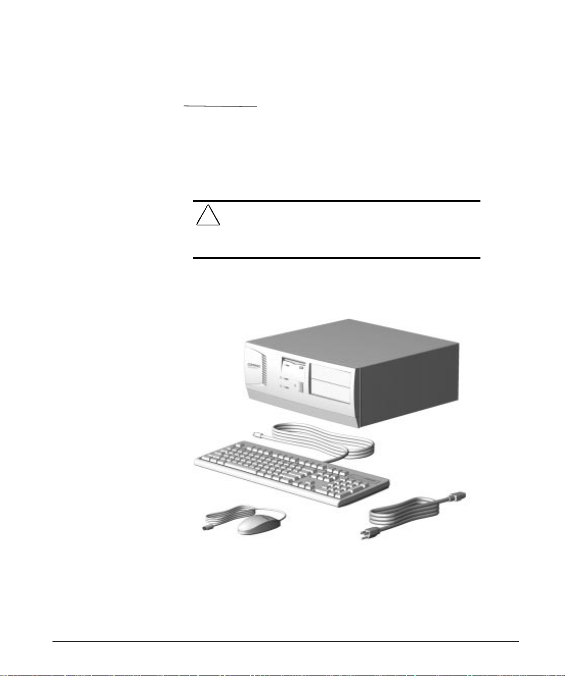
Unpacking the Computer
WARNING:
!
safe and comfortable workstation may result in discomfort or serious
injury. Refer to your
choosing a workspace and creating a safe and comfortable work
environment.
Misuse of your personal computer or failure to establish a
Safety & Comfort Guide
for more information on
Contents of the Box
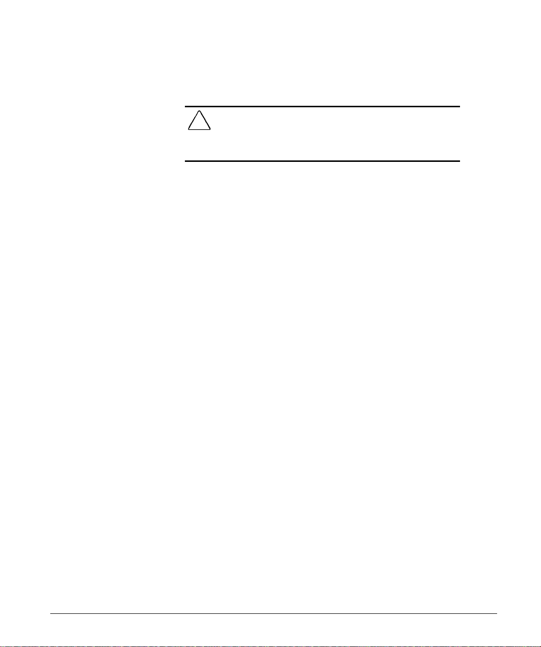
Your packing box includes the Compaq Deskpro 1000 Personal
Computer, keyboard, mouse, power cord, and documentation.
Ensure that you have removed everything from the packing box
before proceeding to the following installation steps.
Reference Guide 1-1
Page 9
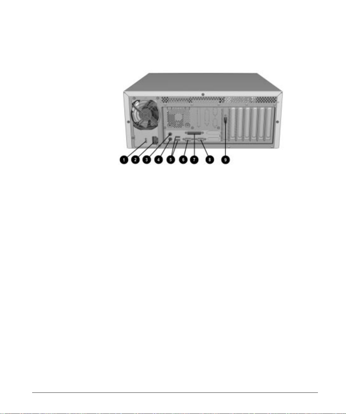
Identifying the Rear Panel Components
Rear Panel Components
Rear Panel Components
1 Voltage Select Switch
(115 V U.S. or 230 V to match geographical
requirements)
2 Power Cord Connector
3 Mouse Connector
4 Keyboard Connector
5 Universal Serial Bus Connectors 1 & 2
6 Serial Connector 1
7 Parallel Connector
8 Serial Connector 2
9 Monitor Connector
1-2 Quick Setup
Page 10
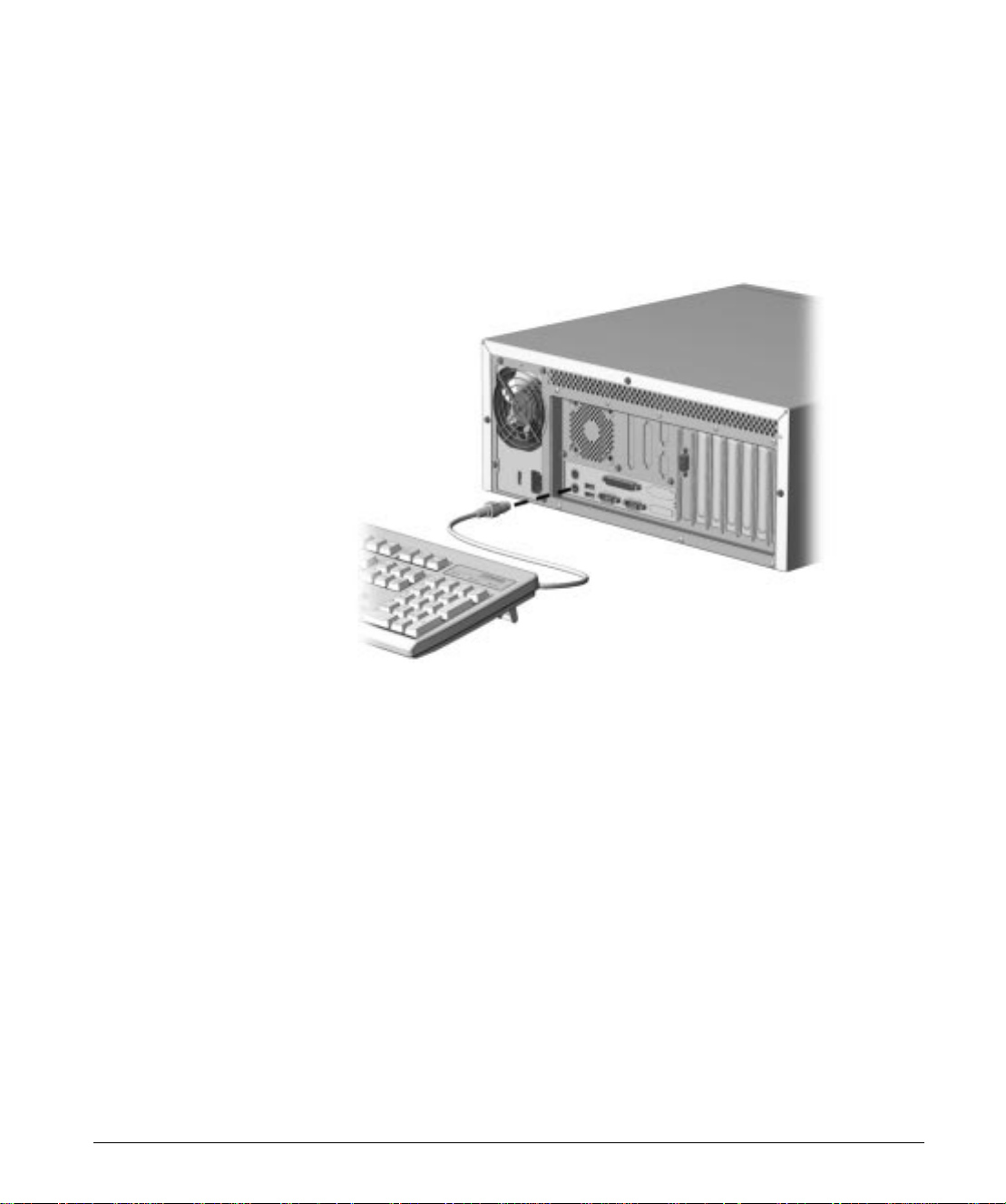
Connecting the Keyboard
1. Locate the keyboard connector on the rear panel of the
computer. This connector is labeled with a keyboard icon.
Connect the keyboard cable to the keyboard connector.
2.
Reference Guide 1-3
Page 11
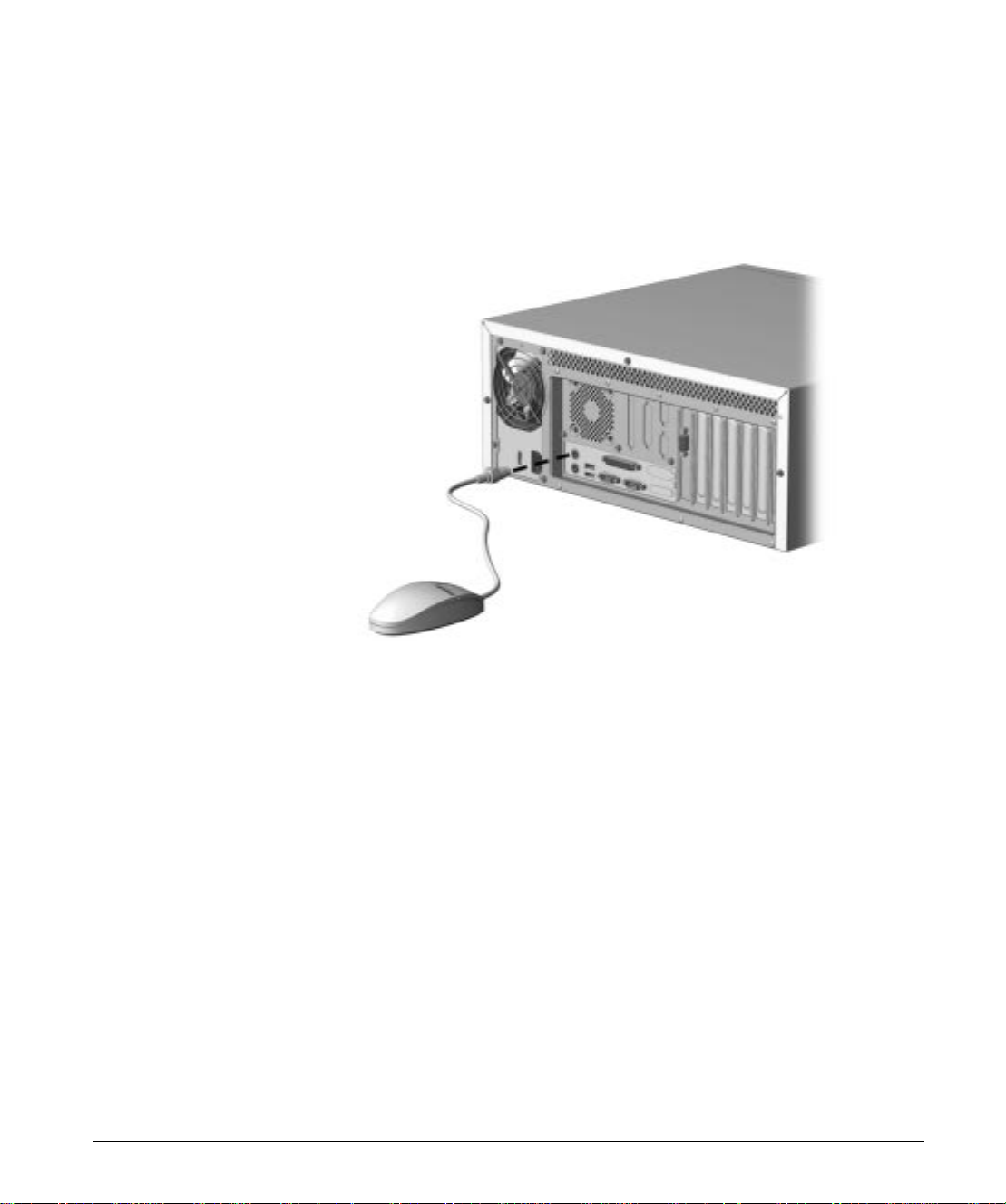
Connecting the Mouse
1. Locate the mouse connector on the rear panel of the
computer. This connector is labeled with a mouse icon.
Connect the mouse cable to the mouse connector.
2.
1-4 Quick Setup
Page 12
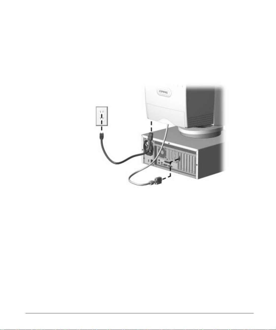
Connecting the Monitor
1. Plug the monitor cable into the monitor connector on the
back of your computer.
Tighten the holding screws on the monitor cable.
2.
Plug the monitor power cord into a grounded outlet.
3.
Reference Guide 1-5
Page 13
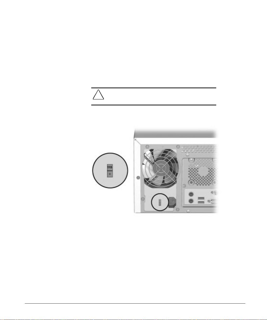
Turning On the Computer
Before turning on the computer, you must first check the
voltage select switch located on the rear panel of the computer.
Choose the appropriate power range for your geographical
1.
area (100-120 or 220-240 VAC).
Verify that the voltage select switch setting is correct for
2.
local power input before removing the label that covers the
power cord receptacle.
WARNING:
!
position (115 or 230 VAC). Failure to do so will result in damage to
the equipment.
Checking the Voltage Select Switch
Ensure that the voltage select switch is in the proper
1-6 Quick Setup
Page 14
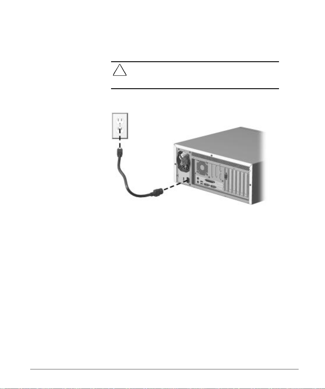
Plug the computer power cord into the power cord connector
3.
on the back of the computer and into a grounded outlet.
WARNING: This equipment is designed for connection to a grounded
!
(earthed) outlet. The 3-prong grounding type plug is an important safety
feature. To avoid the risk of electric shock or damage to your equipment,
do not disable this feature.
Plugging in the Computer
Push in the power button.
4.
Reference Guide 1-7
Page 15
Installing the Software
The first time you turn on your computer, Microsoft
Windows 95 is automatically installed for you.
CAUTION:
TURN OFF YOUR COMPUTER UNTIL THE PROCESS IS COMPLETE.
Turning off your computer during the installation process might
damage the software that runs your computer.
Once the automatic installation has begun, DO NOT
Several important things to remember during this process are:
■
At the beginning of the installation process, you are
prompted to select the appropriate language for your
operating system.
Language selection is final. Make your selection
✎
carefully.
■
The software installation process takes approximately
20 minutes.
■
The computer automatically restarts several times.
■
Carefully read and follow the instructions that appear on the
screen.
■
When the Welcome to Windows 95 screen is displayed, the
installation process is complete.
1-8 Quick Setup
Page 16
chapter
2
C
OMPUTER AT A GLANCE
Features
Compaq Deskpro 1000 Personal Computer
■
Microsoft Windows 95 operating system software
■
One processor installed
■
16 megabytes of random access memory (RAM) standard;
expandable to 256 megabytes
■
256-Kbyte or 512-Kbyte secondary (L2) cache
■
Peripheral Components Interconnect (PCI) chipset used for
PCI/ISA, memory, USB ports, and peripheral control
■
PCI and ISA peripheral connectors
Reference Guide 2-1
Page 17

■
Chassis includes expansion slots for up to seven expansion
boards:
❏
Three dedicated PCI slots
❏
Three dedicated ISA-bus slots
❏
One “combination” slot for either a PCI or an ISA
expansion board
■
200-watt continuous power supply, switch-selectable for
115 and 230 VAC operation
■
Two RS-232C–compatible 9-pin serial connectors
■
One multimode, 25-pin enhanced parallel connector
■
Two Universal Serial Bus (USB) Plug and Play connectors,
for use with USB devices such as a mouse, keyboard, most
joysticks, and other future USB peripherals
■
Five drive bays:
❏
One external 3.5-inch, one-third height diskette drive
installed
❏
One internal 3.5-inch, one-third height drive bay for an
optional drive
❏
One internal 3.5-inch, one-third height hard drive
installed
2-2 Computer at a Glance
❏
Two external 5.25-inch half-height bays for optional
drives
■
One hard drive installed
■
One 1.44-megabyte, 3.5-inch high-density diskette drive
installed
■
Compaq Enhanced Keyboard, featuring Microsoft
Windows–specific keys
■
Mouse
■
Password security features
Page 18
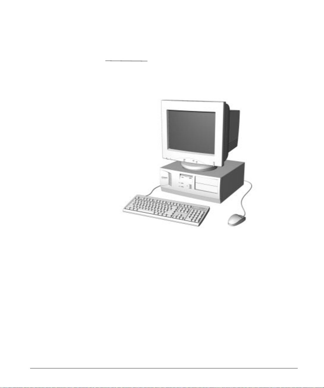
Front Panel Components
Front Panel Components
Front Panel Components
Reference Component
1 Diskette Drive Activity Light
2 Power-On Light
3 Hard Drive Activity Light
4 Diskette Eject Button
5 Power Button
Reference Guide 2-3
Page 19
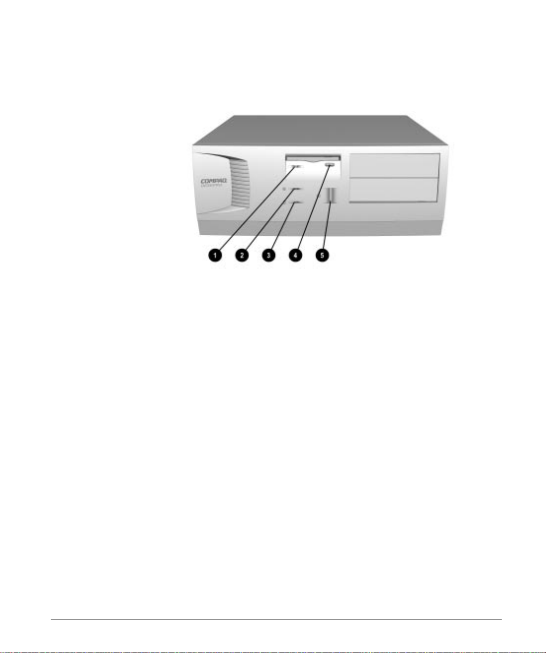
Drive Positions
Drive Positions
Drive Positions
Drive Configuration
1
2
3
4
5
Standard 3.5-inch 1.44-MB diskette drive installed
One 3.5-inch third-height bay for optional drive
Primary hard drive installed (3.5-inch, third-height)
One 5.25-inch half-height bay for optional drive
One 5.25-inch half-height bay for optional drive
2-4 Computer at a Glance
Page 20
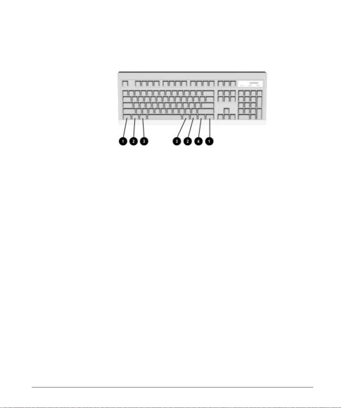
Using the Compaq
Selected multifunctional keys are shown in this drawing.
Enhanced Keyboard
Compaq Enhanced Keyboard
Reference Key Function
1
2
3
4
*Keys available in select geographic regions.
Ctrl Used in combination with another key, its effect depends on the application
software you are using.
Windows
Logo*
Alt Use in combination with another key, its effect depends on the application
Application* Used (like the right mouse button) to open pop-up menus in a Microsoft Office
Used to open the Start menu in Microsoft Windows 95. Used in combination
with other keys to perform other functions (see the following table).
software you are using.
application. May perform other functions in other software applications.
Keyboard Components
Reference Guide 2-5
Page 21
Windows Logo Key Functions
You may use the Windows logo keys in combination with other
keys to perform certain functions in Windows 95, as shown in the
following table:
Windows Logo Key Combinations and Functions
Windows Logo Key
Combination Functionality in Windows 95
Windows logo key + F1 Displays a pop-up menu for the
selected object.
Windows logo key + Tab Activates the next Taskbar button.
Windows logo key + E Launches Explore My Computer.
Windows logo key + F Launches Find Document.
Windows logo key + Ctrl+F Launches Find Computer.
Windows logo key + M Minimizes all open applications.
Shift + Windows logo key + M Undoes Minimize All.
Windows logo key + R Displays Run dialog box.
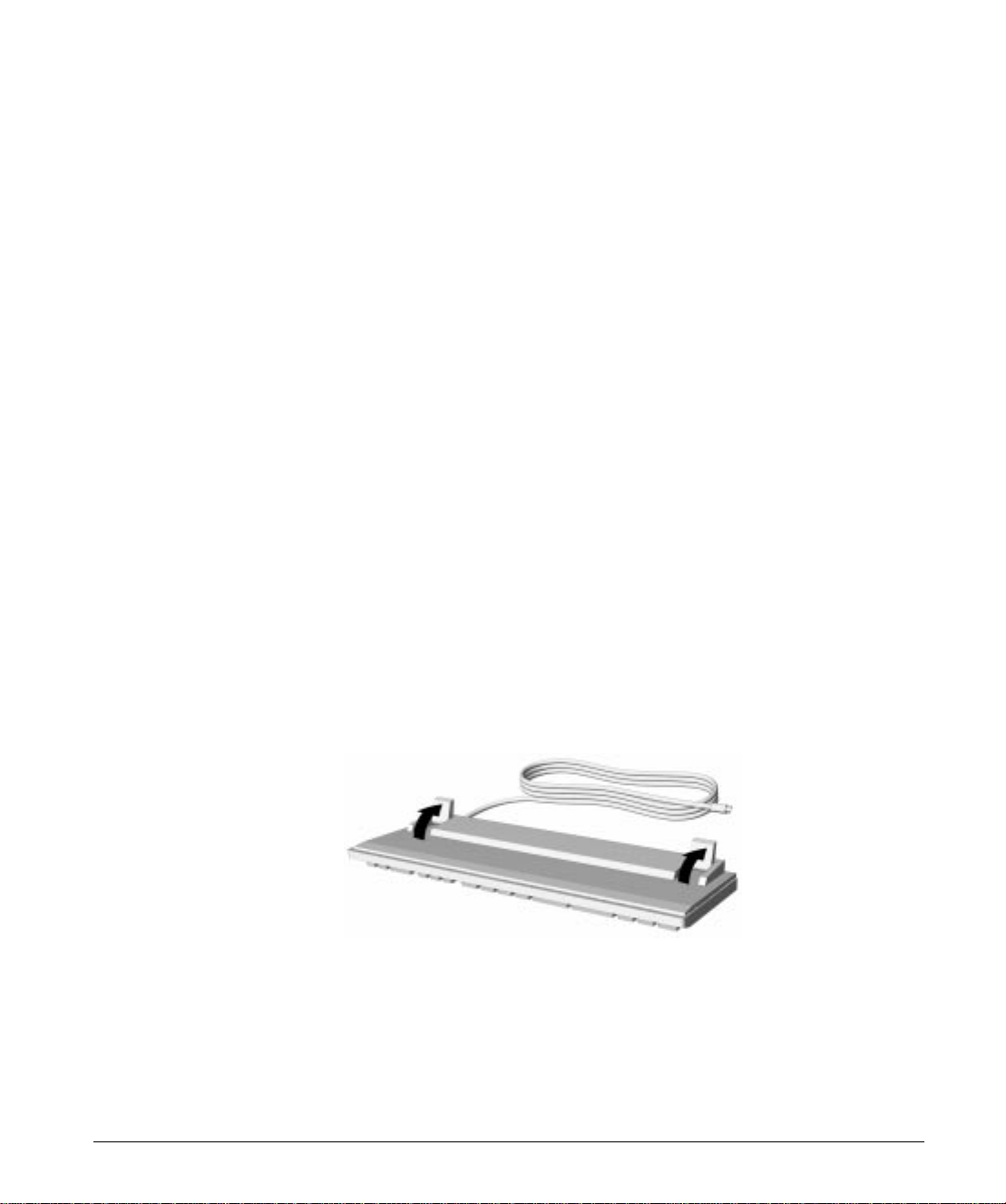
Keyboard Tilt Feet
2-6 Computer at a Glance
The keyboard has feet on the bottom to tilt the keyboard to a
comfortable typing angle.
Keyboard Tilt Feet
Page 22
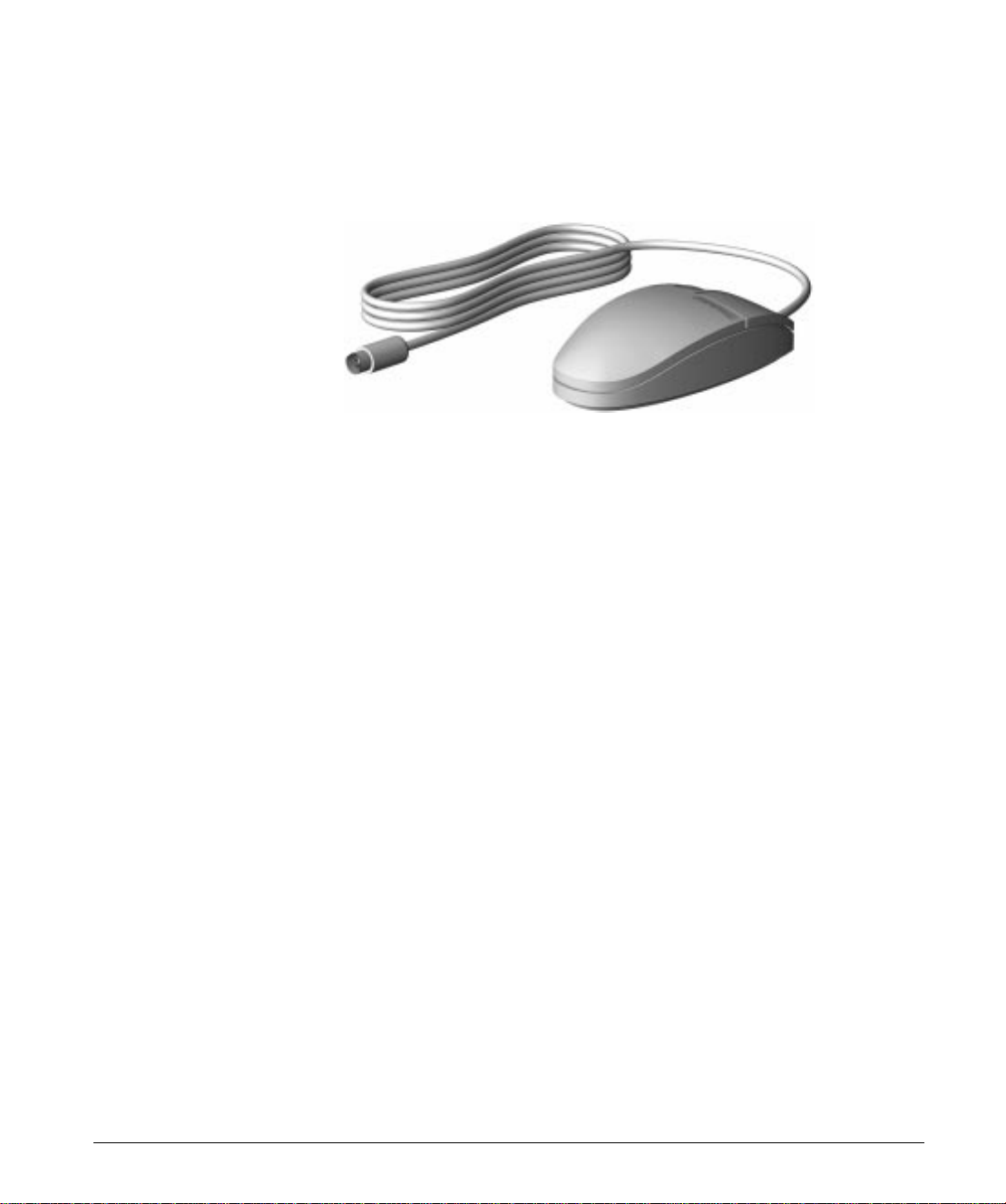
Using the Mouse
The Compaq mouse comes with your computer, but any serial PS/2
mouse may be used. The mouse controls the on-screen pointer or
cursor when you use Windows and other graphical software.
Compaq Mouse
1. Make sure the mouse is properly connected to the computer
and that the computer startup is complete.
2. Place the mouse on a clean, flat surface, such as your
desktop or on a mousepad.
3. Move your mouse across the flat surface and a pointer
moves across your screen.
❏
To type, move the pointer to a spot on the screen
where you want to begin typing, then press and release
(this is called clicking) the left mouse button once. The
cursor will begin blinking at the spot you clicked, and
you may begin typing there.
❏
To make a selection in a program menu, use the mouse
to click on the menu name, then click on your selection
in the drop-down menu list.
❏
To open icons (small pictures that represent files and
programs), position the mouse pointer on the icon, then
double-click.
The double-click speed is timed. If you double-click too
✎
slowly, your computer responds as if you single-clicked twice.
Remember, click quickly.
Reference Guide 2-7
Page 23

Cleaning the Mouse
For the most part, a mouse cleans itself as you move it around.
However, if you find that the pointer does not move smoothly, or
that the ball does not move freely, you should clean the mouse.
1. Turn off your computer.
2. Disconnect the mouse cable from the computer.
3. Turn the mouse upside down.
4. Remove the mouse ball cover.
5. Gently turn the mouse over and let the ball drop into your
6. Use a cotton swab dipped in isopropyl (rubbing) alcohol to
7. Dry the ball with a clean, lint-free cloth.
8. Blow into the ball cage to remove any dust or lint from
hand.
wipe the ball clean. Squeeze the excess liquid out of the
cotton swab before wiping the ball.
inside. (The cage contains rollers like those on a tape
recorder. Use a cotton swab and tape head cleaner to wipe
off any oil on these surfaces. Turn the rollers to clean all
surfaces.)
2-8 Computer at a Glance
9. Put the ball back into the mouse and close the mouse ball
cover.
10. Plug the mouse cable into the computer.
Page 24

Caring for Your Computer
■
Operate the computer on a sturdy, level surface such as
a desk or table.
■
Leave a three-inch (7.6-cm) clearance at the back of the
system unit and above the monitor to permit required
airflow.
■
Never restrict the airflow into the computer by blocking the
front vents or air intake.
■
Do not place the keyboard, with the keyboard feet down,
directly against the front of the unit as this will restrict the
airflow.
■
Never cover the ventilation slots on the monitor with any
type of material.
■
Keep the computer away from excessive moisture, direct
sunlight, and extremes of heat and cold.
■
For information about the recommended temperature and
humidity ranges for your computer, refer to Appendix B,
“Technical Specifications.”
■
Keep liquids away from the computer and keyboard.
For the following suggestions, be sure the computer is
✎
turned off.
■
Clean the exterior of the computer, the monitor casing, and
the outer surfaces of the keyboard with a soft cloth
dampened with water as needed. Wipe with a soft, lint-free
cloth to remove any moisture. Using cleaning products may
discolor or damage the finish.
■
Visible debris underneath or between the keyboard keys
may be removed by vacuuming or gentle shaking.
■
Wipe the monitor screen with a clean cloth moistened with
water or with a towelette designed for cleaning monitors.
Do not use sprays or aerosols directly on the screen, as
liquid may seep into the housing and damage internal
components.
■
Occasionally clean the air vents on the front and back of the
computer. Lint and other foreign matter can block the vents
and limit the airflow.
Reference Guide 2-9
Page 25

Page 26

chapter
3
L
OCATING ADDITIONAL
I
NFORMATION
Using Your Microsoft Windows Guide
Using Windows Online Help
The Microsoft Windows guide included with your computer
explains common tasks so that you can start working on the
computer quickly. Refer to the Microsoft Windows guide for
information about:
■
Using Windows Explorer
■
Creating and deleting files and folders
■
Saving documents
■
Scrolling
■
Setting up a screen saver
■
Using shortcuts
■
Connecting to the Internet
Use Windows online help to find information on a variety of
topics, such as:
■
System settings
■
Customizing the Start menu
■
Sending and receiving data files using your fax/modem
■
Changing the appearance of the desktop
■
Moving and resizing windows
■
Creating icons
■
Using the right mouse button for certain tasks
■
Using networks
Reference Guide 3-1
Page 27

To access Windows help from the Windows desktop, click on
the Start button, then click on Help.
The Help Topics: Windows Help window appears.
Getting to Help from the Start button opens the Windows
general online help. If you use online help in a program, such as
Solitaire, you will get the online help specific to that program.
To access help in a program, click on the Help menu in that
program, or press the F1 key.
All Windows help screens contain some common features:
Contents: Click on the Contents tab to see topics grouped by
subject. Simply double-click on one of the available books, then
double-click on the topic you’d like to learn about. This is a fast
way to find information about common tasks, such as opening
programs.
Index: Click on the Index tab to get an alphabetical list of all
the Windows online help topics. Instead of scrolling, use the
box under 1. Type the first few letters of the word you’re
looking for to jump to the topic you’re looking for. When you
find the topics you want to browse or read, you can double-click
on it or highlight it, then click on the Display button.
Find: Click on the Find tab, and type in a word or phrase in the
box under 1. Type the word(s) you want to find, then click on
the Find Now button. Windows searches for topics related to
the word or phrase you typed. After the search is complete, a list
of related topics is displayed in the box under 3. Click a topic,
then click Display. You can double-click on a topic or highlight
one, then click on the Display button.
3-2 Locating Additional Information
Page 28

chapter
4
S
UPPORT SOFTWARE
Accessing Setup
Using Power Management Setup
Setting Passwords
The Basic Input/Output System (BIOS) software contains a
Setup program for configuring your computer. To access the
Setup program, press and hold the Delete key during computer
startup when the “Press Del to enter Setup” message appears in
the bottom left corner of the computer screen. Once in the Setup
program, use the arrow keys to select your topic and press Enter
to run the desired program.
The Setup program includes Power Management Setup, which
allows you to adjust the power management features of your
computer.
■
Select Disable to disable global power management
features. (This option is the default setting.)
■
Select User Defined to configure your own power
management features.
■
Select MIN Saving to initiate all predefined timers in their
minimum values.
■
Select MAX Saving to initiate all predefined timers in their
maximum values.
The Setup program includes options for setting a Supervisor
Password or a User Password.
The Supervisor Password protects the system configuration
settings from unauthorized modifications.
The User Password functions as a power-on password
preventing unauthorized access to the information stored on
your computer or on the network.
Passwords may be any combination of 1 to 8 alphanumeric
characters.
Reference Guide 4-1
Page 29

Password Prompting
Under the BIOS Feature Setup, you have the option to be
prompted for a password every time you start the computer or
only when you enter the CMOS Setup Utility. To select an
option, under the BIOS Feature Setup:
■
Select System under the Security Option field to be
prompted for the Supervisor Password every time you try to
enter the CMOS Setup Utility and to be prompted for the
User Password every time you turn on the computer.
■
Select Setup under the Security Option field to be prompted
for the password only when you turn on the computer.
Establishing a Supervisor Password
By establishing a Supervisor Password, you can protect the
system configuration and prevent unintentional or unauthorized
configuration changes. Once this password is established, you
cannot change the system configuration until you enter the
password.
1. From Setup, select the Supervisor Password option.
2. Type your password and press
3. You will be asked to confirm the password. Retype the
password and press
Enter
.
Enter
.
Establishing a User Password
4-2 Support Software
If necessary, you may press
✎
and not enter a password.
By establishing a user password, you can prevent unauthorized
access to information stored on the computer or the network.
Once this password is established, you cannot use the computer
until you enter the password.
1. From Setup, select the User Password option.
2. Type your password and press
3. You will be asked to confirm the password. Retype the
password and press
Enter.
Esc
to abort the password selection
Enter.
Page 30

✎
Entering a Password
When prompted, type your current password.
✎
Disabling a Password
1. From Setup, select either the Supervisor Password or User
2. When you are prompted to enter the established password,
Changing a Password
To change a Supervisor or User password, complete the
following steps:
If necessary, you may press
and not enter a password.
Type carefully; for security reasons, the characters you type do not
appear on the screen.
Password option depending on which password you want
to disable.
Enter.
press
A message appears confirming the password is
disabled.
Esc
to abort the password selection
1. Disable the established password by pressing
prompted for the current password.
2. Establish a new password by following the instructions in
“Establishing a Supervisor Password” or “Establishing a
User Password” earlier in this chapter.
Enter
when
Reference Guide 4-3
Page 31

Clearing a User Password
If you forget your password, you cannot access the computer.
You will need to disable the User Password feature by setting
the appropriate jumper on the system board. You will then be
able to access your computer.
1. Turn off the computer and disconnect the power cord from
the electrical outlet.
2. Remove the computer cover.
3. Locate Jumper CPW.
4-4 Support Software
Locating the Password Jumper on the System Board
4. Remove the jumper from the single pin and reinstall it over
both pins.
5. Leave the jumper on for approximately 60 seconds.
6. Remove the jumper from both pins and reinstall on a
single pin.
7. Restart the computer.
Page 32

chapter
5
U
PGRADING THE COMPUTER
This chapter explains how to remove the computer cover,
provides an inside view of the computer, and explains how to
install additional system memory and graphics memory.
For other upgrades, contact your local Compaq authorized
service provider.
Removing the Computer Cover
To install optional equipment, you must remove the computer
cover.
CAUTION:
computer is turned off and that the power cord is disconnected
from the electrical outlet.
To remove the computer cover, complete the following steps:
1. Turn off the computer and any external devices.
2. Disconnect the power cord from the power outlet and any
external devices from the computer.
3. Remove the three screws on the rear panel of the computer.
4. Slide the computer cover backward about 1 inch (2.5 cm);
then, lift it up off the unit.
Before removing the computer cover, ensure that the
Removing the Computer Cover
Reference Guide 5-1
Page 33

Inside View of the Computer
The following illustration provides an inside view of the main
features of the computer.
Inside View of the Computer
Interior Components
Ref. Component
1
2
3
4
5
6
Expansion slots
Power supply
Memory module sockets
Processor
Diskette drive
Internal hard drive
5-2 Reference Guide
Page 34

Adding System Memory
The computer comes with 16 megabytes of single inline memory
modules (SIMMs) or dual inline memory modules (DIMMS)
installed. System memory may be upgraded by adding either
additional SIMM modules or additional DIMM modules.
✎
Compaq strongly recommends not combining DIMMs
and SIMMs.
The four SIMM memory sockets on the system board can be
populated with 8-, 16-, 32-, or 64-megabyte SIMMs. The system
supports up to 256 MB of SIMM memory. SIMMs must be
installed in equally matched pairs; for example, two 8-MB
modules, two 16-MB modules, two 32-MB modules, or two
64-MB modules. If you are mixing extended data out (EDO)
and fast page mode (FPM) DRAM, identical modules must be
installed two at a time, for example, two EDO modules of the
same type, speed, and size; or two FPM DRAM modules of the
same type, speed, and size.
The two DIMM memory sockets on the system board can be
populated with 8-, 16-, 32-, 64-, or 128-MB DIMMs. The
system supports up to 256 MB of DIMM memory. You may
install DIMMs one at a time, but when installing pairs each
module in the pair must be of equal size. For proper system
operation, the DIMMs must be industry standard 168-pin,
66-MHz or faster unbuffered synchronous dynamic random
access memory (SDRAM) DIMMs, or unbuffered EDO
DIMMs. For EDO DIMMs, memory configuration is ×4, ×8,
or ×16. For SDRAM DIMMs, memory configuration is ×8
or ×16; ×4 configuration is not supported. The system will not
start if you use unsupported DIMMs.
Reference Guide 5-3
Page 35

The following illustration shows the memory module sockets
located on the system board.
Locating the Memory Module Sockets on the System Board
Memory Module Sockets
Ref. Component
1
2
3
4
DIMM 1
DIMM 2
SIMM 1 & 2 (Bank 0)
SIMM 3 & 4 (Bank 1)
5-4 Reference Guide
Page 36

Memory Configuration Options
Total System
Memory
8 4 & 4 8
16 4 & 4 4 & 4 8 8
16 8 & 8 16
32 8 & 8 8 & 8 16 16
32 16 & 16 32
64 16 & 16 16 & 16 32 32
64 32 & 32 64
128 32 & 32 32 & 32 64 64
128 64 & 64
256 64 & 64 64 & 64 128 128
SIMM 1 & 2
(BANK 0)
SIMM 3 & 4
(BANK 1) DIMM 1 DIMM 2
Reference Guide 5-5
Page 37

Installing a SIMM
CAUTION:
touch any of the contacts. Doing so may damage the module.
When handling a memory module, be careful not to
1. Turn off the computer and disconnect the power cord from
the electrical outlet.
2. Remove the computer cover.
3. Insert a memory module at a 45-degree angle into a SIMM
memory module socket on the system board 1.
A memory module can be installed in only one way. Match
the notch on the module with the tab on the memory
socket. Push the module down into the socket, ensuring
that the module is fully inserted and properly seated.
5-6 Reference Guide
Installing a SIMM Module
4. Rotate the module to an upright position, allowing the
latches to snap into place 2.
5. Repeat steps 3 and 4 for each module that you want to
install.
Page 38

Installing a DIMM
CAUTION:
touch any of the contacts. Doing so may damage the module.
When handling a memory module, be careful not to
1. Turn off the computer and disconnect the power cord from
the electrical outlet.
2. Remove the computer cover.
3. Press outward on both latches 1 of the DIMM socket at the
same time and insert the memory module 2 into the
socket.
4. A memory module can be installed in only one way. Match
the notch on the module with the tab on the memory
socket. Push the module down into the socket, ensuring
that the module is fully inserted and properly seated 3.
Installing a DIMM Module
5. Repeat steps 3 and 4 for each module that you want to
install.
After all memory modules are installed, replace the
computer cover, plug in the computer power cord, and turn
on the computer. The computer recognizes system memory
upgrades and automatically reconfigures the computer.
Reference Guide 5-7
Page 39

Upgrading Graphics Memory
1. Turn off the computer and disconnect the power cord from
the electrical outlet.
2. Remove the computer cover.
3. Remove the screw at the top of the expansion slot and
remove the graphics controller board.
4. Place the graphics board on a grounded, flat surface and
install the upgrade memory module.
Installing Additional
Drives
5-8 Reference Guide
Installing a Graphics Memory Upgrade Module
5. Replace the graphics board into the same expansion slot.
6. Replace the screw into the expansion slot.
This computer contains available drive bays for optional drives.
Contact your local Compaq authorized service provider for
information on upgrading your computer.
Page 40

chapter
6
T
ROUBLESHOOTING
This chapter provides information on how to identify and
correct some common disk, display, memory, and software
problems. It also identifies and explains some common
messages you may receive on the screen.
Consult Appendix C, "Error Messages," for an explanation of
specific messages that may display during the Power-On SelfTest (POST) at startup.
Helpful Hints
If you encounter some minor problem with your computer,
monitor, or software, refer to the following list of general
suggestions before taking further action:
■
Check that the computer and monitor are plugged into a
working electrical outlet.
■
Check to see that the computer is turned on and the green
power light is on.
■
Check to see that the monitor is turned on and the green
monitor light is on.
■
Turn up the brightness and contrast controls of the monitor
if the monitor is dim.
■
Press and hold any key. If the system beeps, then your
keyboard should be operating correctly.
■
Check all cable connections for loose connections or
incorrect connections.
■
Check that all jumper settings have been set correctly.
Reference Guide 6-1
Page 41

■
Be sure that all the needed device drivers have been
installed (for example, if you are using a printer, you need a
printer driver).
■
Be sure that you have made all necessary changes to the
CONFIG.SYS file.
■
Remove the diskette from the diskette drive when you turn
on your computer.
Messages on the Screen
Many times a message or prompt is displayed on the screen.
This message does not necessarily mean that an error condition
exists. It may simply be the system prompt or an information
message.
Some examples of information messages follow:
■
A number indicating the amount of memory in your system.
■
A> or A:—This is a prompt indicating that you are working
from the diskette drive (drive A).
■
C> or C:—This is a prompt indicating that you are working
from the hard drive (drive C).
6-2 Troubleshooting
Page 42

Solving Minor Problems
You may be able to easily resolve the minor problems described
in this section. If a problem persists and you are unable to resolve
it yourself, contact your Compaq authorized dealer or reseller.
Solving Minor Problems
Problem Cause Solution
Computer won't turn on Computer is not connected to
an external power source.
Cables to the external power
source are unplugged.
A PCI or ISA card that has
been installed is defective.
Computer doesn't automatically display the date
and time
RTC (real-time clock) battery
may need to be replaced.
Battery life is approximately
5 years.
Connect to an external power source.
Ensure that cables connecting the computer and
the external source are plugged in properly.
Remove any adapter card that was just
installed.
Replace the RTC battery. Refer to Appendix F,
"Installing a New Battery," for installation
instructions, or contact your Compaq authorized
dealer or reseller for RTC battery replacement.
Reference Guide 6-3
Page 43

Solving Disk Problems
Common causes and solutions for disk problems are listed in the
following table:
Solving Disk Problems
Problem Cause Solution
Diskette drive light
stays on
Diskette drive cannot
write to a diskette
Diskette is damaged. In Windows 95, run Scan Disk. Click Start Æ
Programs Æ Accessories Æ System Tools Æ
ScanDisk.
Diskette is incorrectly
inserted.
Drive button is not pushed
in.
Software program is
damaged.
Drive cable is not properly
connected.
Diskette is not formatted. Format the diskette.
Diskette is write-protected. Use another diskette or remove the write protection.
Writing to the wrong drive. Check the drive letter in your path statement.
Not enough space is left on
the diskette.
Remove diskette and reinsert.
Push in drive button.
Check the program diskettes.
Reconnect drive cable.
Use another diskette.
Continued
6-4 Troubleshooting
Page 44

Solving Disk Problems
Continued
Problem Cause Solution
A problem has
occurred with a disk
transaction
Diskette drive cannot
read a diskette
Drive not found Cable is loose. Check connections.
Nonsystem disk
message
The directory structure is
bad, or there is a problem
with a file.
Diskette is not formatted. Format the diskette.
You are using the wrong
diskette type for the drive
type.
The system is trying to start
from a nonsystem diskette.
In Windows 95, run Scan Disk. Click Start Æ
Programs Æ Accessories Æ System Tools Æ
ScanDisk.
Check the type of drive you are using and use the
correct diskette type.
Remove the diskette from the drive.
Reference Guide 6-5
Page 45

Solving Display Problems
If you encounter display problems, refer to the documentation
included with your monitor and to the common causes and
solutions listed in the following table:
Solving Display Problems
Problem Cause Solution
Blank screen Monitor is not turned on and
the monitor light is not on.
The cable connections are
not correct.
The energy saver feature has
been enabled.
The RGB (Red, Green, Blue)
input switch on the back of
the monitor is incorrectly set.
You are using a fixed-sync
monitor and it won't sync at
the resolution chosen.
Turn on the monitor and check that the monitor light
is on.
Check the cable connection from the monitor to the
computer and to the electrical outlet.
Press any key or click the mouse button and, if it is
set, type your password.
Set the monitor's RGB input switch to 75 ohms and, if
there is a sync switch, set it to External.
Be sure that the monitor can accept the same sweep
rate as the resolution chosen.
Continued
6-6 Troubleshooting
Page 46

Solving Display Problems
Continued
Problem Cause Solution
Monitor does not
function properly
when used with
energy saver features
Garbled characters on
the screen mixed with
text
Video colors are
wrong
Dim characters The brightness and contrast
Blurry display or
requested resolution
cannot be set
Monitor without energy
saver capabilities is being
used with energy saver
features enabled.
The
ANSI.SYS
CONFIG.SYS
in the
This indicates that either the
cabling or monitor
impedance is incorrect.
controls are not set
properly.
Cables are not properly
connected.
The RGB switch on the
back of the monitor is
incorrectly set.
If the graphics controller
was upgraded, the correct
display drivers may not be
loaded.
driver is not
file.
Disable monitor energy saver feature.
You may need to add the
CONFIG.SYS
DEVICE=C:\ANSI.SYS
1. If you are using BNC cables, be sure that the
Red, Green, and Blue BNC cables are
connected to the corresponding monitor
connectors.
2. Be sure your monitor's RGB inputs are set to
75 ohms.
Adjust the monitor brightness and contrast
controls.
Check that the video cable is securely connected
to the video card and the monitor.
Set the RGB switch (and sync options, if this
option is available) to 75 ohms, with the sync set
to "external." Refer to the documentation included
with the monitor.
Install the display drivers on the diskette included
in the upgrade kit.
file. Add the following line to the file:
ANSI.SYS
driver to the
Continued
Reference Guide 6-7
Page 47

Solving Display Problems
Continued
Problem Cause Solution
Screen goes blank You may have a screen
blanking utility installed or
energy saver features are
enabled.
The picture is broken
up, or it rolls, jitters, or
blinks
Monitor overheats There is not enough ventilation
Cursor will not move
using the arrow keys
on the keypad
The monitor connections may
be incomplete or the monitor
may be incorrectly adjusted.
space for proper airflow.
The Num Lock key may be on. Press the Num Lock key. The light should not
Press any key or type the password.
1. Be sure the monitor cable is securely
connected to the computer.
2. In a 2-monitor system or if another monitor
is in close proximity, be sure the monitors
are not interfering with each other's
electromagnetic field by moving them
apart.
Leave at least 3 inches (7.6 cm) of ventilation
space. Be sure there is nothing sitting on top of
the monitor obstructing the air flow.
be on if you want to use the arrow keys.
6-8 Troubleshooting
Page 48

Solving Printer Problems
If you encounter printer problems, refer to the documentation
included with your printer and to the common causes and
solutions listed in the following table:
Solving Printer Problems
Problem Cause Solution
Printer will not
print
Printer will not
turn on
Prints garbled
information
Printer is
offline
Printer is not turned on and online. Turn the printer on and make sure it is online.
The correct printer drivers for your
application are not installed.
If you are on a network, you may
not have made the connection to
the printer.
The cables may not be connected
properly.
The correct printer drivers for your
application are not installed.
The cables may not be connected
properly.
The printer may be out of paper. Check the paper tray and refill it if it is empty. Select
Install the correct printer drivers for your application.
Make the proper network connections to the printer.
Reconnect all cables and check the power cord and
electrical outlet.
Install the correct printer driver for your application.
Reconnect all cables.
online.
Reference Guide 6-9
Page 49

Solving Hardware Installation Problems
You may need to reconfigure the computer when you add or remove
hardware. If you install a Plug and Play device, Windows automatically
recognizes the device and configures the computer.
If you install a non–Plug and Play device, you must reconfigure the
computer after completing installation of the new hardware.
In Windows 95, double-click the Add New Hardware icon in the
Control Panel and follow the instructions that appear on the screen.
Solving Hardware Installation Problems
Problem Cause Solution
A new device is not
recognized as part of
the computer system
The Setup program has not
been run to configure the new
device.
Cable(s) of new external
device are loose or power
cables are unplugged.
Power switch of new external
device is not turned on.
Run the Setup program.
Ensure that all cables are properly and securely
connected and that pins in the cable or
connector are not bent down.
Turn off the computer, turn on the external
device, then turn on the computer to integrate
the device with the computer system.
6-10 Troubleshooting
Page 50

Solving Memory Problems
If you encounter memory problems, some common causes and
solutions are listed in the following table:
Solving Memory Problems
Problem Cause Solution
System won't boot or
does not function
properly after installing
additional memory
modules.
Out of Memory error Memory configuration may not
Memory count during
POST is wrong
Insufficient memory
error during operation
Memory module is not the
correct type or speed grade
for the system.
be set up correctly.
You have run out of memory
to run the application.
The memory modules may not
be installed correctly.
Too many Terminate and Stay
Resident programs (TSRs)
are installed.
You have run out of memory
for your application.
If using DIMMs, replace module with an
industry-standard 168-pin synchronous DRAM
DIMM that meets the following criteria:
■ Rated for 66-MHz or faster
operation.
■ Has an access time (CLK to Q) of
9 ns or less.
■ Supports CAS latency 2 or 3
operation.
If using SIMMs, replace module with an
industry-standard SIMM module.
In Windows 95, use Device Manager to check
memory configuration.
Check the application documentation to
determine the memory requirements.
Check that the memory modules have been
installed correctly.
Close any TSRs that you do not need.
Check the memory requirements for the
application or add more memory to the
computer.
Reference Guide 6-11
Page 51

Contacting Compaq
Customer Support
For help and service, contact your Compaq authorized reseller
or dealer. For a list of phone numbers, see the “Worldwide
Telephone Numbers” table.
✎
If you take your computer to a Compaq authorized reseller,
dealer, or service provider for service, remember to provide
the setup and power-on passwords, if they are set.
Worldwide Telephone Numbers
Locate your geographical area from the following table and use
one of the telephone numbers for Compaq assistance.
General Information Numbers
technical assistance, and the location of your nearest Compaq
authorized dealer, reseller, or service provider.
Technical Support Numbers
analyzing system configuration and diagnostic problems or
troubleshooting.
Customer Support Numbers
support programs including warranty, product catalogs, and
white papers.
PaqFax Numbers
technical and product specific information that is transmitted to
any fax machine. PaqFax is available 24 hours a day.
✎
Telephone numbers are subject to change without notice.
Automatic facsimile response system for
Product information,
Hardware technical support in
Information on service and
6-12 Troubleshooting
Page 52

Worldwide Telephone Numbers
Location Country Code Telephone Number
Argentina
General Information +54 -1-796-1616
Technical Support +54 -1-796-1717
Australia
General Information 61-2-9911-1999
Technical Support 61-2-9911-1955
PaqFax 61-2-9911-1982
Austria
General Information +43 01-7956770
Technical Support Business Products +43 01-7956-7700
Technical Support Presario Products +43 045-889-145-1450
(ATS 22.30/min.)
Technical Support +43 01-7956-7999
Ordering Backup Software +31 -55-538-43-39
Belgium/Luxemburg
General Information* Bel
Lux
Compaq Care Center* Bel
Lux
Compaq Care Center Fax Bel
Lux
General Fax +32 -2-725-22-13
FaxPaq +32 -2-716-96-96
BBS +32 -2-716-95-92
Ordering Backup Software +32 -2-716-96-78
Ordering Backup Software Fax +32 -2-716-96-79
Brazil
General Information +55 -11-246-7866
* Toll-free, domestic telephone number
02/713.12.34
49.12.34
02/713.12.34
49.12.34
02/713.14.44
49.12.34
continued
Reference Guide 6-13
Page 53

Worldwide Telephone Numbers
continued
Location Country Code Telephone Number
Canada
General Information 905-707-1715
Technical Support* 1-800-OKCOMPAQ
(1-800-652-6672)
Customer Support* 1-800-263-5868
Ordering Backup Software* 1-800-952-7689
Battery Pack Recycling* 1-800-263-5868
Caribbean
General Information 1-281-514-4220
Technical Support 1-281-518-2200
Chile
General Information +56 -2-274-1911
Technical Support +56 -2-274-3007
China
General Information (86) 10 68313399
Technical Support (86) 10 68346721
BBS (86) 10 68346709
PaqFax (86) 10 68346724
Compaq Verification Center (86) 10 68346739
Compaq Management Service Center (86) 10 68313399-5873
Colombia
General Information +57 -1-312-0201
Technical Support +57 -1-345-0266
Czech Republic
General Information +420 -2-232-8772
Technical Support +420 -2-232-8772
* Toll-free, domestic telephone number
continued
6-14 Troubleshooting
Page 54

Worldwide Telephone Numbers
continued
Location Country Code Telephone Number
Denmark
General Information +45 -45-90-45-90
Technical Support +45 -45-90-45-45
Finland
General Information +358 -0-615-599
Technical Support* 9800-206-720
QuickLine (BBS) +358 -0-6155 9870
France
General Information +33 0803 804 805 (1,09 FTTC/mn)
Technical Support +33 0803 813 823 (1,09 FTTC/mn)
Germany
General Information* 0180/3 22 12 21
General Information Fax* 0180/3 22 12 20
All Products Fax* 0180/5 21 21 17
Desktop Hotline* 0180/5 21 21 11 (0,48 DM/min.)
Notebook Hotline* 0180/5 21 21 11 (0,48 DM/min.)
Server Hotline* 0180/5 21 21 11 (0,48 DM/min.)
Presario Hotline* 0190/88 80 81
(0,12 DM/2 sec. or 3,60 DM/min.)
QuickLine* 0180/5 21 21 18 (0,48 DM/min.)
Hong Kong
General Information 852-28681382
Technical Support 852-90116633
PaqFax 852-28671648
* Toll-free, domestic telephone number
continued
Reference Guide 6-15
Page 55

Worldwide Telephone Numbers
continued
Location Country Code Telephone Number
Hungary
General Information +36 1-457-3650
Technical Support +36 1-457-3680
Customer Support +36 1-457-3650
Email Info.hu@compaq.com
India
General Information 91-80-559-6023
PaqFax 91-80-559-8989
BBS 91-80-559-8900
Israel
General Information +972 -3-6363-444
Fax +972 -3-639-6601
Technical Support +49 -89-9933-2891
Italy
Presales Info 167 464911
Technical Support
(products other than Presario) +39 02 69633281
Technical Support Presario +39 02 69633280
BBS +39 -2-89-200-222
Ordering Backup Software +39 -1-67-859-030
Fax +39 02 69633282
Japan
General Information* 0120-101-589
Technical Support* 0120-101-589
Windows 95 Support* 0120-505-589
Presario* 0120-099-589
Ordering Backup Software* 0120-250-589
FaxStation 81-3-5402-0991
* Toll-free, domestic telephone number
continued
6-16 Troubleshooting
Page 56

Worldwide Telephone Numbers
continued
Location Country Code Telephone Number
Korea
General Information 82-2-3470-07001
Technical Support 82-2-523-3575
82-082-902-77774
Malaysia
General Information 603-717-1188
Technical Support 603-718-1636
Mexico
General Information +52 -5-229-7900
Technical Support +52 -5-229-7910
PaqFax +52 -5-229-7920
Netherlands
General Information 0182-565805
Customer Support
(products other than Presario)* 0900-1681616 (Dfl. 0.75/min.)
Fax (products other than Presario)* 0900-8991116 (Dfl. 0.40/min.)
Presario Customer Support* 0900-2023091 (Dfl. 0.75/min.)
Presario Fax* 0900-8212391 (Dfl. 0.40/min.)
New Zealand
General Information 64-9-307-3969
Norway
General Information +47 -22-07-20-20
Technical Support +47 -22-07-20-20
Poland
General Information +48 -22-630-3535
Technical Support +48 -22-630-3535
* Toll-free, domestic telephone number
continued
Reference Guide 6-17
Page 57

Worldwide Telephone Numbers
continued
Location Country Code Telephone Number
Portugal
General Information +351 -1-412-8400
Technical Support +351 -1-412-8460
Russia
General Information +7 -095-967-1700
Technical Support +7 -095-967-1700
Singapore
General Information 65-753-6688
Customer Support Center 65-750-3030
PaqFax 65-750-4514
South Africa
General Information 27-11-728-6999
Technical Support 27-11-728-6999
Spain
General Information +34 -902-10-14-14
Technical Support Business Products +34 1-377-81-87
Technical Support Presario +34 1-377-81-92
BBS +34 1-6400267
Software Fulfillment +34 900-993103
Fax +34 1-377-81-83
Sweden
General Information +46 -8-703 52 00
Sales Information +46 -8-587 711 40
Technical Support, key accounts +46 -8-587 711 40
Technical Support, charged calls* 0729-36 20 00
FaqPax (hämtfax) +46 -8-703 52 25
QuickLine (BBS) +46 -8-703 52 20
* Toll-free, domestic telephone number
continued
6-18 Troubleshooting
Page 58

Worldwide Telephone Numbers
continued
Location Country Code Telephone Number
Switzerland
InfoLine 0844 844 111
Equipment Hotline
(Desktop and Notebooks)
Systems Hotline
(Server and Internetworking Products)
Presario Hotline* 157 64 00 (SFr. 3.13/min.)
QuickLine Bulletin Board 01/8 38 24 21
Ordering Backup Software 0800 556 206
Taiwan
General Information 886-2-7351000
Technical Support 886-2-3761170
Email Address taiwan@netgate.compaq.com
Thailand
General Information 62-2-679-6222
United Arab Emirates (Dubai)
General Information +97 14 -818100
United Kingdom
General Information 0141-270 4000
FaxPaq 0181-332-3550
QuickLine Bulletin Board 0181-332-9499
* Toll-free, domestic telephone number
01/838 22 22 (German)
01/838 22 23 (French)
01/838 22 22 (German)
01/838 22 23 (French)
continued
Reference Guide 6-19
Page 59

Worldwide Telephone Numbers
continued
Location Country Code Telephone Number
United States
Technical Support* 1-800-OKCOMPAQ
(1-800-652-6672)
General Information* 1-800-345-1518
PaqFax* 1-800-345-1518
Download Facility (modem access only) 1-281-518-1418
Ordering Backup Software* 1-800-952-7689
Battery Pack Recycling* 1-800-524-9859
Venezuela
General Information +58 -2-953-8844
* Toll-free, domestic telephone number
6-20 Troubleshooting
Page 60

appendix
A
A
GENCY REGULATORY NOTICES
Federal
Communications
Commission Notice
This equipment has been tested and found to comply with the
limits for a Class B digital device, pursuant to Part 15 of the
FCC Rules. These limits are designed to provide reasonable
protection against harmful interference in a residential
installation. This equipment generates, uses, and can radiate
radio frequency energy and, if not installed and used in
accordance with the instructions, may cause harmful
interference to radio communications. However, there is no
guarantee that interference will not occur in a particular
installation. If this equipment does cause harmful interference
to radio or television reception, which can be determined by
turning the equipment off and on, the user is encouraged to try
to correct the interference by one or more of the following
measures:
■
Reorient or relocate the receiving antenna.
■
Increase the separation between the equipment and the
receiver.
■
Connect the equipment into an outlet on a circuit different
from that to which the receiver is connected.
■
Consult the dealer or an experienced radio or television
technician for help.
Modifications
Cables
The FCC requires the user to be notified that any changes or
modifications made to this device that are not expressly
approved by Compaq Computer Corporation may void the user's
authority to operate the equipment.
Connections to this device must be made with shielded cables
with metallic RFI/EMI connector hoods to maintain compliance
with FCC Rules and Regulations.
Reference Guide
A-1
Page 61

Mouse
This device complies with Part 15 of the FCC Rules. Operation
is subject to the following two conditions: (1) this device may
not cause harmful interference, and (2) this device must accept
any interference received, including interference that may cause
undesired operation.
Declaration of Conformity for Products Marked with FCC Logo, United States Only
This device complies with Part 15 of the FCC Rules. Operation is
subject to the following two conditions: (1) this device may not cause
harmful interference, and (2) this device must accept any interference
received, including interference that may cause undesired operation.
For questions regarding this declaration, contact:
Compaq Computer Corporation
P. O. Box 692000, Mail Stop 510101
Houston, Texas 77269-2000
Or call:
(281) 514-3333
To identify this product, refer to the Series/model number found on the
product.
Canadian Notice
Avis Canadien
Agency Regulatory Notices
A-2
This Class B digital apparatus meets all requirements of the
Canadian Interference-Causing Equipment Regulations.
Cet appareil numérique de la classe B respecte toutes les
exigences du Règlement sur le matériel brouilleur du Canada.
Page 62

European Notice
Japanese Notice
Products with the CE Marking comply with both the EMC
Directive (89/336/EEC) and the Low Voltage Directive
(73/23/EEC) issued by the Commission of the European
Community.
Compliance with these directives implies conformity to the
following European norms:
■
EN55022 (CISPR 22) - Radio Frequency Interference
■
EN50082-1 (IEC801-2, IEC801-3, IEC801-4) Electromagnetic Immunity
■
EN60950 (IEC950) - Product Safety
Reference Guide
A-3
Page 63

Battery Replacement Notice
Power Cord Set
Requirements
WARNING:
!
real-time clock circuit. There is a danger of explosion and risk of
personal injury if the battery is incorrectly replaced or mistreated.
Do not attempt to recharge the battery, disassemble it, immerse it
in water, or dispose of it in fire. Refer to Appendix F for
replacement procedures.
For more information about real-time clock battery replacement or
proper disposal, contact your Compaq authorized reseller or
service provider.
The voltage select switch feature on the computer permits it to
operate from any line voltage between 100 to 120 volts AC or
between 200 to 240 volts AC.
The power cord set (flexible cord or wall plug) received with the
computer meets the requirements for use in the country where
you purchased the equipment.
Power cord sets must meet the requirements of the country
where you use the computer. For more information on power
cord set requirements, contact your Compaq authorized reseller
or service provider.
Your computer is provided with a battery-powered
General Requirements
Agency Regulatory Notices
A-4
The requirements listed below are applicable to all countries:
1. The length of the power cord set must be at least 5.00 feet
(1.5 m) and a maximum of 9.75 feet (3.0 m).
2. All power cord sets must be approved by an acceptable
accredited agency responsible for evaluation in the country
where the power cord set will be used.
3. The power cord set must have a minimum current capacity
of 10A and a nominal voltage rating of 125 or 250 volts
AC, as required by each country’s power system.
4. The appliance coupler must meet the mechanical
configuration of an EN 60 320/IEC 320 Standard Sheet
C13 connector, for mating with appliance inlet on the rear
of the unit.
Page 64

Country-Specific
Requirements
If you encounter some minor problem with your computer,
monitor, or software, refer to the following list of general
suggestions before taking further action:
Power Cord Set Requirements - By Country
Accredited
Country
Australia EANSW 1
Austria OVE 1
Belgium CEBC 1
Canada CSA 2
Denmark DEMKO 1
Finland FIMKO 1
France UTE 1
Germany VDE 1
Italy IMQ 1
Japan MITI 3
Norway NEMKO 1
Sweden SEMKO 1
Switzerland SEV 1
United Kingdom BSI 1
United States UL 2
Agency
Applicable Note
Numbers
Notes:
1. The flexible cord must be <HAR> Type HO5VV-F,
3-conductor, 1.0 mm
2
conductor size. Power cord set
fittings (appliance coupler and wall plug) must bear the
certification mark of the agency responsible for evaluation
in the country where it will be used.
Reference Guide
A-5
Page 65

2. The flexible cord must be Type SJT or equivalent, No. 18
AWG, 3-conductor. The wall plug must be a two-pole
grounding type with a NEMA 5-15P (15A, 125V) or
NEMA 6-15P (15A 250V) configuration.
3. The appliance coupler, flexible cord, and wall plug must
bear a "T" mark and registration number in accordance
with the Japanese Dentori Law. The flexible cord must be
Type VCT or VCTF, 3-conductor, 0.75mm
2
conductor size.
The wall plug must be a two-pole grounding type with a
Japanese Industrial Standard C8303 (15A, 125V)
configuration.
U.S. and Foreign
Patents
Models of this product operating at 100 MHz or less are
covered by the following U.S. Patents:
4,574,279 5,125,088
5,381,530 5,101,497
5,538,947
Models operating at greater than 100 MHz are covered by the
following U.S. Patents:
4,574,279 5,125,088
5,101,497 5,538,947
Other U.S. and foreign patents may apply.
Agency Regulatory Notices
A-6
Page 66

appendix
B
T
ECHNICAL SPECIFICATIONS
This appendix provides physical and performance specifications
for the computer, keyboard, and mouse.
System Specifications
U. S. Metric
Dimensions
Height
Width
Length
Weight 22.9 lb 10.4 kg
Power Supply
Operating Voltage Range
Rated Voltage Range
Rated Line Frequency
Rated Input Current (maximum) 6 A 3 A
Power Output 200 W 200 W
Environmental Requirements
Temperature
Operating 50° to 95°F10° to 35°C
Shipping -4° to 140°F -20° to 60°C
Humidity (noncondensing)
Operating 8% to 90% 8% to 90%
Nonoperating 5% to 95% 5% to 95%
6.5 in
16.88 in
16.25 in
90-132 VAC
100-120 VAC
50-60 Hz
16.51 cm
42.88 cm
41.28 cm
180-264 VAC
200-240 VAC
50-60 Hz
Continued
Reference Guide
B-1
Page 67

System Specifications
Continued
U. S. Metric
Maximum Altitude (unpressurized)
Operating 10,000 ft 3048 m
Nonoperating 30,000 ft 9144 m
Heat Dissipation (nominal) 770 Btu/hr 3.23 kg-
cal/min
Keyboard
U.S. Metric
Dimensions
Height
Width
Depth
Weight 1.98 lb 0.9 kg
1.58 in
17.95 in
6.63 in
4.0 cm
45.6 cm
16.8 cm
Technical Specifications
B-2
Page 68

2-Button Mouse
U.S. Metric
Dimensions
Height
Length
Width
Weight 4.59 oz 130 g
Base Resolution 400 dpi 400 dpi
Tracking Speed
(maximum)
Temperature
Operating
Storage
Lifetime
Mechanical
Switch
Relative Humidity 10% to 90%,
ESD No soft errors through 10 kV;
1.34 in
4.45 in
2.36 in
10 in/sec 25 cm/sec
32°F to 104°F
-4°F to 140°F
Exceeds 300 miles
Exceeds 1 million
operations
noncondensing
No hard errors through 15 kV; specific performance
depends on host system
3.4 cm
11.3 cm
6.0 cm
0°C to 40°C
-20°C to 60°C
Exceeds 483 km
Exceeds 1 million operations
10% to 90%, noncondensing
Reference Guide
B-3
Page 69

Page 70

appendix
C
E
RROR
This appendix lists the error codes that you may encounter
during the Power-On Self-Test (POST), the probable source of
the problem, and what steps you can take to resolve the error
condition.
M
ESSAGES
Power-On Self-Test Messages
Message Probable Cause Recommended Action
The computer beeps.
The beeps consist of
continuous long
beeps.
The computer beeps.
The beeps consist of
a single long beep
followed by two short
beeps.
BIOS ROM
Checksum Error System Halted
CMOS Battery Failed CMOS battery is no longer
CMOS Checksum
Error - Defaults
Loaded
No system memory present. Add system memory.
A video error has occurred
and the BIOS cannot initialize
the video screen to display
any additional information.
The checksum of the BIOS
code in the BIOS chip is
incorrect, indicating the BIOS
code may have become
corrupt.
functional.
The checksum of CMOS is
incorrect, so the system loads
the default equipment
configuration.
Ensure the VGA card is installed correctly and that
the monitor cable is well connected.
Contact your Compaq authorized dealer or service
provider to replace the BIOS.
Contact your Compaq authorized dealer or service
provider for a replacement battery.
A checksum error may indicate that CMOS has
become corrupt. This error may have been caused
by a weak battery. Check the battery and replace if
necessary.
Continued
Reference Guide
C-1
Page 71

Power-On Self-Test Messages
Continued
Message Probable Cause Recommended Action
CPU at nnnn Displays the running speed of
the CPU.
Display Switch is Set
Incorrectly
Press Esc to Skip
Memory Test
Floppy Disk(s) Fail
(40)
Disk Boot Failure,
Insert System Disk
and Press Enter
Hard Disk Install
Failure
Hard Disk(s)
Diagnosis Fail
Keyboard Error or
No Keyboard
Present
The display switch on the
system board can be set to
either monochrome or color.
This message indicates the
switch is set to a different
setting than indicated in
Setup.
The system is testing memory. The user may press
Cannot find or initialize the
floppy drive controller or the
drive.
No hard drive installed. Install a hard drive.
Cannot find or initialize the
hard drive controller or the
drive.
The system has run specific
disk diagnostic routines. This
message appears if one or
more hard disks return an
error when the diagnostics
run.
Cannot initialize the keyboard. Ensure the keyboard is attached correctly and no
None necessary.
Determine which setting is correct, and then either
turn off the system and change the jumper, or enter
Setup and change the Video selection.
to skip the full memory
Esc
test.
Ensure the controller is installed correctly. If no
floppy drives are installed, be sure the Diskette
Drive selection in Setup is set to None.
This will only occur if the BIOS supports low level
format which the current BIOS does not.
If this happens often, the hard disk may be
damaged and needs to be replaced.
keys are pressed during POST. To purposely
configure the system without a keyboard, set the
error halt condition in Setup to Halt on All, but
Keyboard. The BIOS then ignores the missing
keyboard during POST.
Continued
C-2
Error Messages
Page 72

Power-On Self-Test Messages
Continued
Message Probable Cause Recommended Action
Keyboard is Locked
Out - Unlock the
Key
Memory Test This message displays during
Memory Test Fail If POST detects an error
Primary Master Hard
Disk Fail
Primary Slave Hard
Disk Fail
Secondary Master
Hard Disk Fail
Secondary Slave
Hard Disk Fail
This message usually
indicates that one or more
keys have been pressed
during the keyboard tests.
a full memory test, counting
down the memory areas being
tested.
during memory testing,
additional information appears
giving specifics about the type
and location of the memory
error.
POST detects an error in the
primary master IDE hard
drive.
POST detects an error in the
primary slave IDE hard drive.
POST detects an error in the
secondary master IDE hard
drive.
POST detects an error in the
secondary slave IDE hard
drive.
Ensure no objects are resting on the keyboard.
None.
If this happens often, the memory module may
need to be replaced.
Ensure the controller is installed correctly, the cable
is attached correctly, and the hard disk jumper is
set to primary master. If no hard drive is installed,
be sure the hard drive selection in Setup is set to
none.
Ensure the controller is installed correctly, the cable
is attached correctly, and the hard disk jumper is
set to primary slave. If no hard drive is installed, be
sure the hard drive selection in Setup is set to none.
Ensure the controller is installed correctly, the cable
is attached correctly, and the hard disk jumper is
set to secondary master. If no hard drive is
installed, be sure the hard drive selection in Setup
is set to none.
Ensure the controller is installed correctly, the cable
is attached correctly, and the hard disk jumper is
set to secondary slave. If no hard drive is installed,
be sure the hard drive selection in Setup is set to
none.
Reference Guide
C-3
Page 73

Page 74

appendix
D
S
HIPPING YOUR COMPUTER
To prepare the computer for shipping, follow these guidelines:
1. Back up the hard drive files onto diskettes (or onto an
external hard drive or other external storage device, if
available). To prevent data loss, do not expose your backup
diskettes to electrical or magnetic impulses.
2. Remove all diskettes from the diskette drives; remove the
CD from the CD-ROM drive, if any.
3. Turn off the computer and external devices.
4. Disconnect the power cord from the electrical outlet, then
from the computer.
5. Disconnect your printer and any other external devices
from their power sources, then from the computer.
✎
Make sure all boards are seated properly in the expansion slots
with their retaining screws in place before shipping the computer.
6. Pack the computer in its original packing box or in similar
packaging with sufficient packing material to protect it.
✎
For environmental nonoperating temperature ranges, refer to
Appendix B, "Technical Specifications."
Reference Guide
D-1
Page 75

Page 76

appendix
E
E
LECTROSTATIC DISCHARGE
A discharge of static electricity from a finger or other conductor
may damage system boards or other static-sensitive devices.
This type of damage may reduce the life expectancy of the
device.
Preventing
Electrostatic
Damage
Grounding Methods
To prevent electrostatic damage, observe the following
precautions:
■
Avoid hand contact by transporting and storing products in
static-safe containers.
■
Keep electrostatic-sensitive parts in their containers until
they arrive at static-free workstations.
■
Place parts on a grounded surface before removing them
from their containers.
■
Avoid touching pins, leads, or circuitry.
■
Always be properly grounded when touching a staticsensitive component or assembly.
There are several methods for grounding. Use one or more of
the following methods when handling or installing electrostaticsensitive parts:
■
Use a wrist strap connected by a ground cord to a grounded
workstation or computer chassis. Wrist straps are flexible
straps with a minimum of 1 megohm +/- 10 percent
resistance in the ground cords. To provide proper ground,
wear the strap snug against the skin.
Reference Guide
E-1
Page 77

■
Use heelstraps, toestraps, or bootstraps at standing
workstations. Wear the straps on both feet when standing on
conductive floors or dissipating floor mats.
■
Use conductive field service tools.
If you do not have any of the suggested equipment for proper
grounding, contact a Compaq authorized reseller or service
provider.
For more information on static electricity, contact your
✎
Compaq authorized dealer, reseller, or service provider.
Electrostatic Discharge
E-2
Page 78

appendix
F
I
NSTALLING A NEW BATTERY
When your computer no longer automatically displays the
correct date and time, it may mean the battery providing power
to the real-time clock needs to be replaced. Battery life is
usually about five to ten years under normal use. When
replacing the battery, use a 3-volt replacement battery.
WARNING:
!
There is a risk of fire and chemical burn if the battery pack is
handled improperly. Do not disassemble, crush, puncture, short
external contacts, dispose in water or fire, or expose it to
temperatures higher than 60ºC (140ºF).
This computer contains a lithium-ion battery pack.
In North America, dispose of nickel metal
hydride or lithium-ion batteries by taking
advantage of the Compaq battery recycling
program. You will be provided with a postagepaid battery pack mailer preaddressed to a
reclamation facility where the metals are
recycled. Call the telephone number listed for
your location in Chapter 6 for more
information.
In Europe, do not dispose of batteries with
general household waste. Dispose of or recycle
them by using the public collection system or
returning them to Compaq, your authorized
Compaq partners, or their agents.
Reference Guide
F-1
Page 79

1. Turn off the computer and disconnect the power cord from
the electrical outlet.
2. Remove the computer cover.
3. Locate the battery on the system board.
4. Press down on the retainer latch and slide the battery out of
the holder.
Installing a New Battery
F-2
Installing a New Battery
5. Insert the new battery into the holder.
6. Replace the computer cover.
7. Plug in the computer.
8. Turn on the computer and follow the instructions on the
screen.
Page 80

A
accessing
Setup, 4-1
B
battery
replacement, F-1
beeps, C-1
buttons
diskette eject, 2-3
power, 2-3
C
I
NDEX
diskette drive, 2-2
diskette eject button, 2-3
display problems
solving, 6-6
drive bays, 2-2
dual inline memory modules (DIMMs),
5-4
E
electrostatic discharge
grounding methods, E-1
preventing damage, E-1
error messages, C-1
expansion slots, 2-2
cache, 2-1
caring for your computer, 2-9
computer
features, 2-1
plugging in, 1-7
setting up, 1-1
turning on, 1-6
upgrading, 5-1
computer care
cleaning exterior, 2-9
routine care, 2-9
shipment preparation, D-1
computer specifications, B-1
connectors
rear panel, 1-2
cover
removing, 5-1
D
DIMMs (dual inline memory modules),
5-4
installing, 5-8
disk problems
solving, 6-4
F
front panel components, 2-3
G
graphics memory
upgrading, 5-9
grounding methods, E-1
H
hardware installation problems
solving, 6-10
I
inside view of the computer, 5-3
K
keyboard, 2-2
connecting, 1-3
connector, 1-2
specifications, B-2
tilt feet, 2-6
Windows Logo Keys, 2-6
Reference Guide I-1
Page 81

L
language selection, 1-8
lights
diskette drive activity, 2-3
hard drive activity, 2-3
power-on, 2-3
M
memory, 2-1
configuration, 5-6
solving problems, 6-11
messages on the screen, 6-2
Microsoft Windows Guide, 3-1
Microsoft Windows 95, 1-8
monitor
connecting, 1-5
connector, 1-2
mouse, 2-2
cleaning, 2-8
connecting, 1-4
connector, 1-2
specifications, B-3
using, 2-7
O
operating system, 2-1
P
parallel connector, 1-2, 2-2
passwords
changing, 4-3
clearing, 4-4
disabling, 4-3
entering, 4-3
establishing, 4-2
prompting, 4-2
setting, 4-1
Supervisor Password, 4-1
User Password, 4-1
Peripheral Components Interconnect
(PCI), 2-1
power button, 2-3
power cord
connector, 1-2
set requirements, A-4
Power Management Setup, 4-1
power problems
solving, 6-3
power-on light, 2-3
Power-On Self-Test (POST) messages,
C-1
preventing electrostatic damage, E-1
grounding methods, E-1
printer problems
solving, 6-9
R
rear panel components, 1-2
S
security features
passwords, 4-1
serial connector, 1-2, 2-2
Setup
accessing, 4-1
shipment preparation, D-1
SIMMs (single inline memory
modules), 5-4
installing, 5-7
single inline memory modules
(SIMMs), 5-4
software
installing, 1-8
solving minor problems, 6-3
specifications
computer, B-1
keyboard, B-2
mouse, B-3
Supervisor Password, 4-1
changing, 4-3
clearing, 4-4
entering, 4-3
establishing, 4-2
support software, 4-1
synchronous dynamic random access
memory (SDRAM), 2-1
I-2 Index
Page 82

system memory
adding, 5-4
configuration, 5-6
system specifications, B-1
T
technical support, 6-12
telephone numbers, 6-12
troubleshooting
contacting Compaq customer
support, 6-12
disk problems, 6-4
display problems, 6-6
hardware installation problems, 6-10
helpful hints, 6-1
memory problems, 6-11
messages on the screen, 6-2
power problems, 6-3
printer problems, 6-9
solving minor problems, 6-3
U
Universal Serial Bus (USB) Plug and
Play connector, 1-2, 2-2
upgrading the computer
graphics memory, 5-9
inside view of the computer, 5-3
installing additional drives, 5-9
removing the computer cover, 5-1
system memory, 5-4
USB connector, 1-2, 2-2
User Password, 4-1
changing, 4-3
clearing, 4-4
entering, 4-3
establishing, 4-2
using the mouse, 2-7
V
voltage select switch, 1-2, 1-6
W
Windows Logo Key functions, 2-6
Windows Online Help, 3-1
Reference Guide I-3
Page 83

 Loading...