

Page 1

Designjet SD Pro Scanner
Service manual
Page 2

© Copyright Hewlett-Packard Company 2014
Legal notices
For HP Internal Use Only
1st edition
This document contains proprietary
information that is protected by copyright. All
rights are reserved. No part of this document
may be photocopied, reproduced, or translated
to another language without the prior written
consent of Hewlett-Packard Company.
Page 3

Notices
Warranty
The information contained in this
document is subject to change without
notice.
Hewlett-Packard makes no warranty of
any kind with regard to this material,
including, but not limited to, the implied
warranties of merchantability and
fitness for a particular purpose.
Hewlett-Packard shall not be liable for
errors contained herein or for incidental or
consequential damages in connection with
the furnishing, performance, or use of this
material.
WARNING! The procedures described in
this manual are to be performed by HPqualified service personnel only.
Electrical Shock Hazard
Serious shock hazard leading to death or
injury may result if you do not take the
following precautions:
●
Ensure that the AC power outlet
(mains) has a protective earth
(ground) terminal.
●
Disconnect the product from the
power source prior to performing any
maintenance.
●
Prevent water or any other liquids
from running onto electrical
components or circuits, or through
openings in the enclosure.
Electrostatic Discharge
See
Electrostatic Discharge (ESD)
Precautions on page 48 for precautions
you should take to prevent damage to the
printer circuits from electrostatic
discharge.
WARNING! The Warning symbol calls
attention to a procedure, practice, or the
like, which, if not correctly performed or
adhered to, could result in personal injury.
Do not proceed beyond a Warning symbol
until the indicated conditions are fully
understood and met.
CAUTION: The Caution symbol calls
attention to an operating procedure,
practice, or the like, which, if not correctly
performed or adhered to, could result in
damage to or destruction of part or all of
the product. Do not proceed beyond a
Caution symbol until the indicated
conditions are fully understood and met.
Safety Symbols
General definitions of safety symbols are
given immediately after the table of
contents.
Content Management Department, Large Format Printing
Barcelona Division,
Hewlett-Packard Espanola, S.A.
Camí de Can Graells, 1–21
08174 Sant Cugat del Vallès
Spain
ENWW iii
Page 4

iv Notices ENWW
Page 5

Using this Manual
Purpose
This Service Manual contains information necessary to troubleshoot and service:
●
HP Designjet SD Scanner Pro
For information about using the product, see the corresponding user guide.
This Service Manual is about the Scanner and the integration with the printer as a copier. In order to
troubleshoot the printer, see the corresponding Service Manual for the printer.
Readership
The procedures described in this Service Manual are to be performed by HP Certified service personnel only.
Part Numbers
Part Numbers for service parts can be found in
Parts and Diagrams on page 43.
ENWW v
Page 6

vi Using this Manual ENWW
Page 7

Table of contents
1 Troubleshooting ........................................................................................................................................... 1
Troubleshooting tips ............................................................................................................................................. 2
Is the problem with the Printer or the Scanner? ................................................................................................... 2
Image-quality problems ........................................................................................................................................ 2
Output problems .................................................................................................................................................... 2
Troubleshooting System Error Codes ................................................................................................................... 3
Using the Service Tools from the Touchscreen .................................................................................................... 3
Troubleshooting Issues ......................................................................................................................................... 7
Troubleshooting print-quality and copy issues .................................................................................................... 8
Troubleshooting general scanner issues ............................................................................................................ 11
Troubleshooting Specific Scanner Issues ........................................................................................................... 17
Most common Image Quality issues ................................................................................................................... 19
Cleaning the Scanning Area ................................................................................................................................. 20
Troubleshooting Specific Panel PC Problems ..................................................................................................... 22
Touch screen fails ................................................................................................................................................ 26
Upgrade Scanner Software ................................................................................................................................. 26
2 System Error Codes ...................................................................................................................................... 28
System Error Codes for the Scanner Only ........................................................................................................... 29
Software Related Errors ...................................................................................................................................... 30
Error Codes for the JetImage Software RIP ........................................................................................................ 36
Error Messages for the Touch Screen ................................................................................................................. 40
3 Parts and Diagrams ..................................................................................................................................... 43
Scanner ................................................................................................................................................................ 44
Panel PC ............................................................................................................................................................... 45
4 Removal and Installation ............................................................................................................................. 47
Introduction ......................................................................................................................................................... 48
Safety Precautions .............................................................................................................................................. 48
Electrostatic Discharge (ESD) Precautions ......................................................................................................... 48
Required Tools ..................................................................................................................................................... 48
Open the CIS Unit ................................................................................................................................................. 49
Scanner Controller Board .................................................................................................................................... 50
ENWW vii
Page 8

Right Side Cover ................................................................................................................................................... 51
Power Supply ....................................................................................................................................................... 52
Left Side Cover ..................................................................................................................................................... 54
Stepper Motor Assembly ..................................................................................................................................... 55
Tacho Sensor ....................................................................................................................................................... 57
Paper and Lid Sensors ......................................................................................................................................... 58
Complete CIS Unit ................................................................................................................................................ 59
Power Entry Module ............................................................................................................................................ 60
Cable Interface ..................................................................................................................................................... 61
Spring for CIS Bridge ............................................................................................................................................ 62
Pressure Rollers .................................................................................................................................................. 63
viii ENWW
Page 9

1 Troubleshooting
●
Troubleshooting tips
●
Is the problem with the Printer or the Scanner?
●
Image-quality problems
●
Output problems
●
Troubleshooting System Error Codes
●
Using the Service Tools from the Touchscreen
●
Troubleshooting Issues
●
Troubleshooting print-quality and copy issues
●
Troubleshooting general scanner issues
●
Troubleshooting Specific Scanner Issues
●
Most common Image Quality issues
●
Cleaning the Scanning Area
●
Troubleshooting Specific Panel PC Problems
●
Touch screen fails
●
Upgrade Scanner Software
ENWW 1
Page 10

Troubleshooting tips
1. First record whether the problem is with the Printer, the Scanner, or the Touch Screen.
2. Make sure that the scanning area is completely clean.
3. Test 20: Noise Test can help you find where the scanning area is dirty.
4. The SCAN dump files can help you to understand the light profile of the affected scanner.
5. Remember, in order to cancel when copying, press the Cancel button on the Touch Screen and the
Cancel button on the printer.
Is the problem with the Printer or the Scanner?
If you experience the following symptoms, the problem could be related to the scanner:
●
System Error on the Touch Screen.
●
LED’s flashing on the Scanner Operator Panel.
●
WIDEsystem error message.
●
Vertical lines (either color or black) in the scanned image.
If you experience the following symptoms, then perform an Image Preview and send a Test Print:
●
Image Quality Problems.
●
No Output
●
Output is not as expected.
If the Image preview fails, this points to a problem with the Scanner. If the Test Print fails, this points to a
problem with the Printer.
Image-quality problems
If you have Image Quality problems in any prints, try the following:
1. Print out a file already stored or print out a demo file.
2. Once the print is finished, insert it into the Scanner.
3. Once scanned, print out the scanned image.
●
If the scanned image already shows the problem, then the problem is associated to the scanner.
●
If the scanned image looks fine, but the print looks incorrect, then the problem is most likely associated
to the printer
Output problems
If the output is not as you expected it to be, try the following:
●
Check all the settings in the Software: Color Settings and Margins.
●
Check media settings: Media profile (in software) and media loaded in the printer (front panel selection)
should be the same.
2 Chapter 1 Troubleshooting ENWW
Page 11

●
Perform Color Calibration (both Scanner and printer).
●
Check the Preview Image.
If there is no output at all, then try the following:
●
Check that both the scanner and the printer are correctly connected to the network.
●
Check the selected settings: List, Collate, Scan to file...
Troubleshooting System Error Codes
Chapter 2, System Error Codes on page 28, contains a list of system error codes and their respective
descriptions and recommended corrective actions. Only try one recommended action at a time and check if
the error code has disappeared.
Using the Service Tools from the Touchscreen
Here we briefly describe the various tests found in the software Service Tools menu (called SCANtest 6 in
previous systems).
The purpose of the Service Tools is to support the troubleshooting and adjustment of the Scanner.
To access the software you must go to the Setup tab and to: Options, System, Service (this part is password
protected, the password is ’support'.
When Service Tools has been started, the Scanner is switched ON in Test Mode, and the Diagnostic LED on the
Operator Panel is turned ON.
NOTE: The word camera is used in some service tests, and in this document to refer to the CIS elements.
Service Tools Menu
●
Test 1: Set Serial Number
●
Test 6: Motor Test
●
Test 9: Oscilloscope view cameras
●
Test 11: Manual Camera Alignment (Vertical alignment and stitching)
●
Test 12: Manual Scaling Adjustment
●
Test 20: Streak Test
●
Test 42: Backup Calibration and statistics
●
Test 43: Restore Calibration and statistics
●
Test 45: Operator Panel Key Test
●
Test 46: Paper Sensor Test
●
Test 47: Operator Panel LED Test
If Service Tools is started when the scanner is in Error Mode, the Error Code Number and a short description
of the error will be displayed on the screen.
Test 1: Set Serial Number
This test displays general information regarding the scanner. When executed, the test displays the following:
ENWW Troubleshooting System Error Codes 3
Page 12
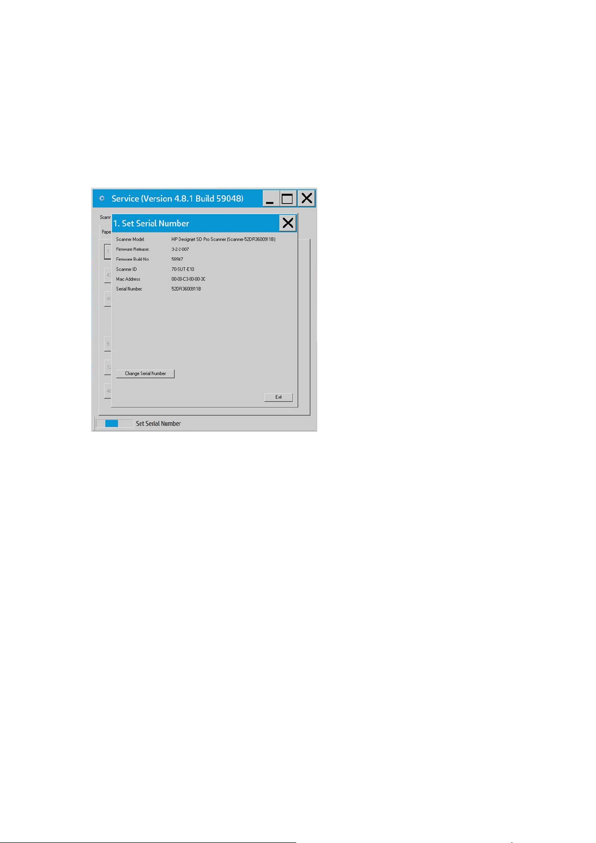
●
Scanner Model:
●
Firmware Release:
●
Firmware Build:
●
Scanner ID:
●
Mac Address:
●
Serial Number:
Test 6: Motor Test
This test checks the functionality of the Stepper Motor and any associated electronics.
When the test is executed, a menu appears that allows you to select the motor speed and the motor
direction.
If the Stepper Motor fails to run when the test is executed, then the Stepper Motor should be replaced.
Test 9: Oscilloscope View
This test contains a Software Oscilloscope that allows you to check the light profile of the CIS elements:
●
Uncorrected light profile shows the raw data from the CIS module.
●
Corrected light profile shows the calibrated data.
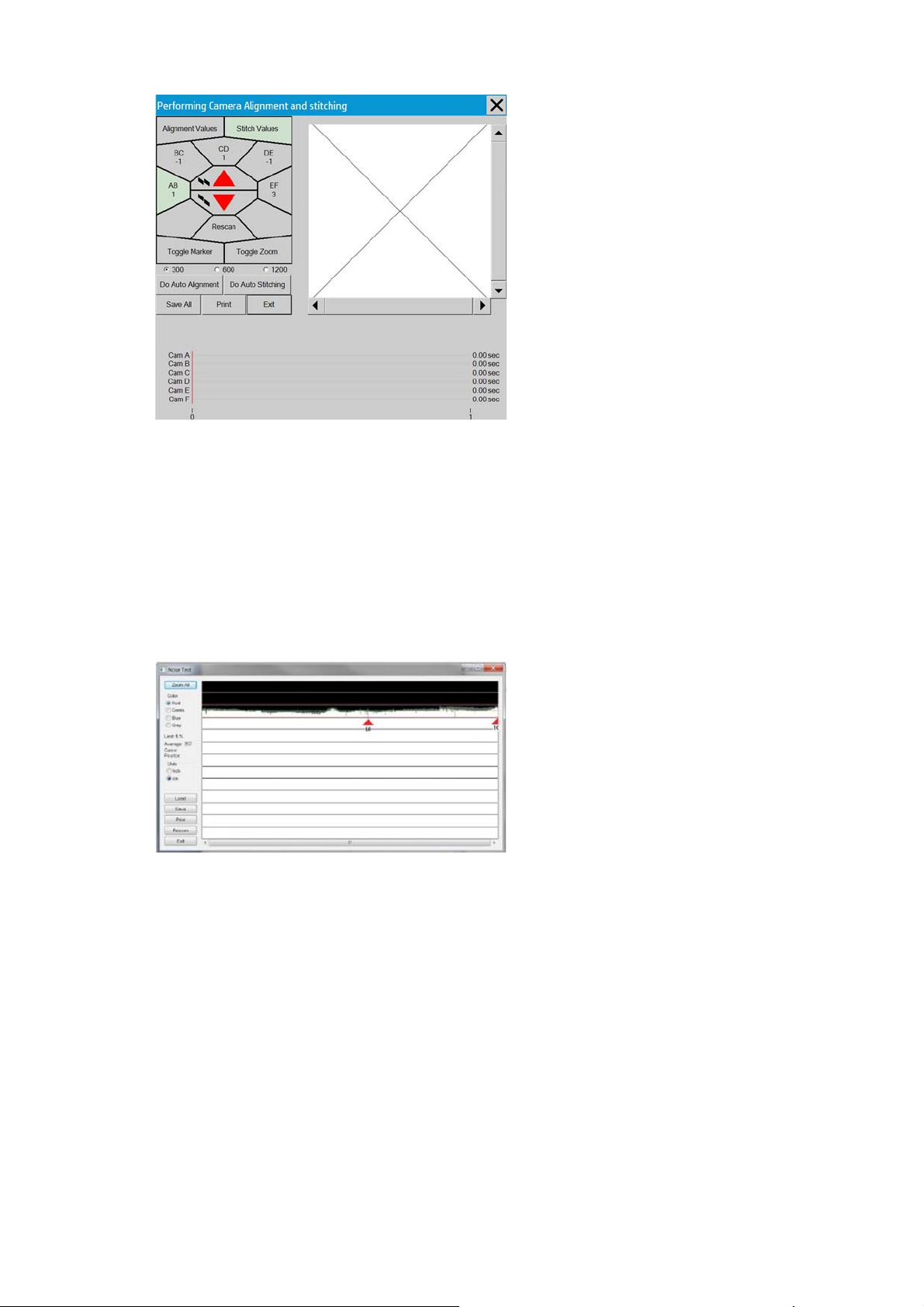
Test 11: Manual Camera Alignment
Allows you to adjust either Vertical Alignment or Stitching between 2 CIS modules:
1. Load the calibration sheet.
2. Select Alignment or Stitching.
3. Select the two CIS modules to adjust (AB, BC, etc...).
4. Use the arrows to either increase or decrease the value until the preview of the transition area between
both CIS modules look correctly aligned or stitched.
4 Chapter 1 Troubleshooting ENWW
Page 13
Test 12: Manual Scaling Adjustment
This test allows you to adjust the Y-Axis Scaling.
The scaling (dpi) in the mechanical scan direction (Y-Axis) depends on the speed of the stepper motor relative
to the scanline Exposure Time. The default motor speed can be changed ± 1%, either from Test 12 or by using
the ‘Scanner Setup/Correction factor …’ option of SW copying. The correction factor is stored in the Flash
Memory on the Scanner Controller Board.
Test 20: Streak test
The purpose of this test is to detect and locate the possible cause (dust, dirt, scratches,..) of vertical lines
running from top to bottom of the scanned image.
This test is very useful if there are image quality issues such as streaks throughout the scan (Scan direction).
It can be determined if the streaks are dust that are:
1. Present in the scanner (Dark streak that goes below the average line).
2. Present during Scanner Maintenance (white streak that goes above the average line).
Insert SM calibration sheet when asked.
Test 42: Backup Calibration and statistics
Use this option to backup the calibrations and the scanner accounting values onto a USB drive.
Test 43: Restore Calibration and Statistics
Use this option to restore the calibrations and accounting values previously backed up onto a USB drive.
Test 45: Operator Panel Key Test
ENWW Using the Service Tools from the Touchscreen 5
Page 14
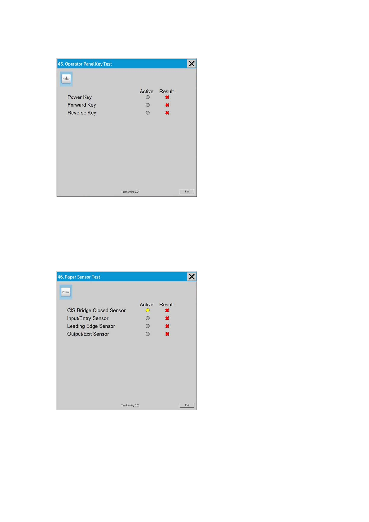
This test checks the functionality of the Keys on the Operator Panel. When pressing each of the keys, the test
will show that the key has been activated, and will show if the result is correct or not.
If the Key test fails, replace the Operators Panel which is included in the Right Side Cover.
Test 46: Paper Sensor Test
This test checks the functionality of the Media Sensors.
To test the Media Sensors, use a sheet of media to activate the different sensors one by one. When activated,
the test will show that the sensor has been activated and will show if the result is correct or not.
For testing the CIS Bridge Sensors; open and close the scanner cover.
If the test fails, then the problem will be related to corresponding Sensor.
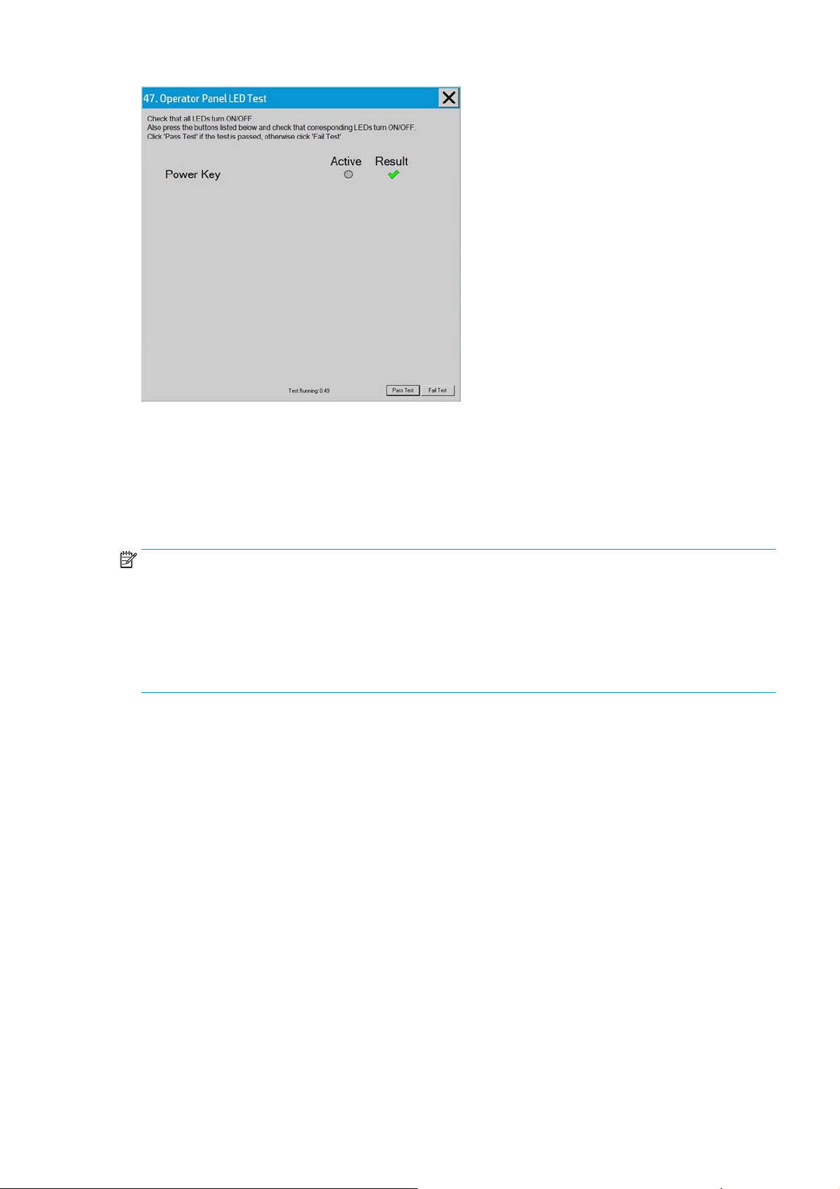
Test 47: Operator panel LED test
This test checks the functionality of the LED Indicators on the Operator Panel. When the test is executed, all
the LEDs are sequentially switched ON/OFF until Test 2 is terminated. If any of the LEDs fail, you will NOT get
an error message, instead the LED will NOT switch ON or OFF. Additionally you are requested to press the
Power button and see if the Power LED is switched ON. If the LED test fails, replace the Replace the Operators
panel which is included in the Right Side cover.
6 Chapter 1 Troubleshooting ENWW
Page 15
Troubleshooting Issues
The following guide will help you to find a solution to some typical problems that some customers may
experience. The problems (P#) that can be solved remotely through on-phone support and customer
intervention are marked C. The problems that require on-site intervention performed by a Support Technician
are marked T.
NOTE: Before sending a Support Technician to the customer, identify whether the problem is related to the
scanner or the Panel PC (PPC).
If the problem is scanner-related, erase the parameter block and run the scanner maintenance. Then perform
the system recover using the most recent version of the software.
If the problem is PPC-related, perform the system recovery using the most recent version of the software.
If the problem persists, try the solutions listed in the tables below.
ENWW Troubleshooting Issues 7
Page 16
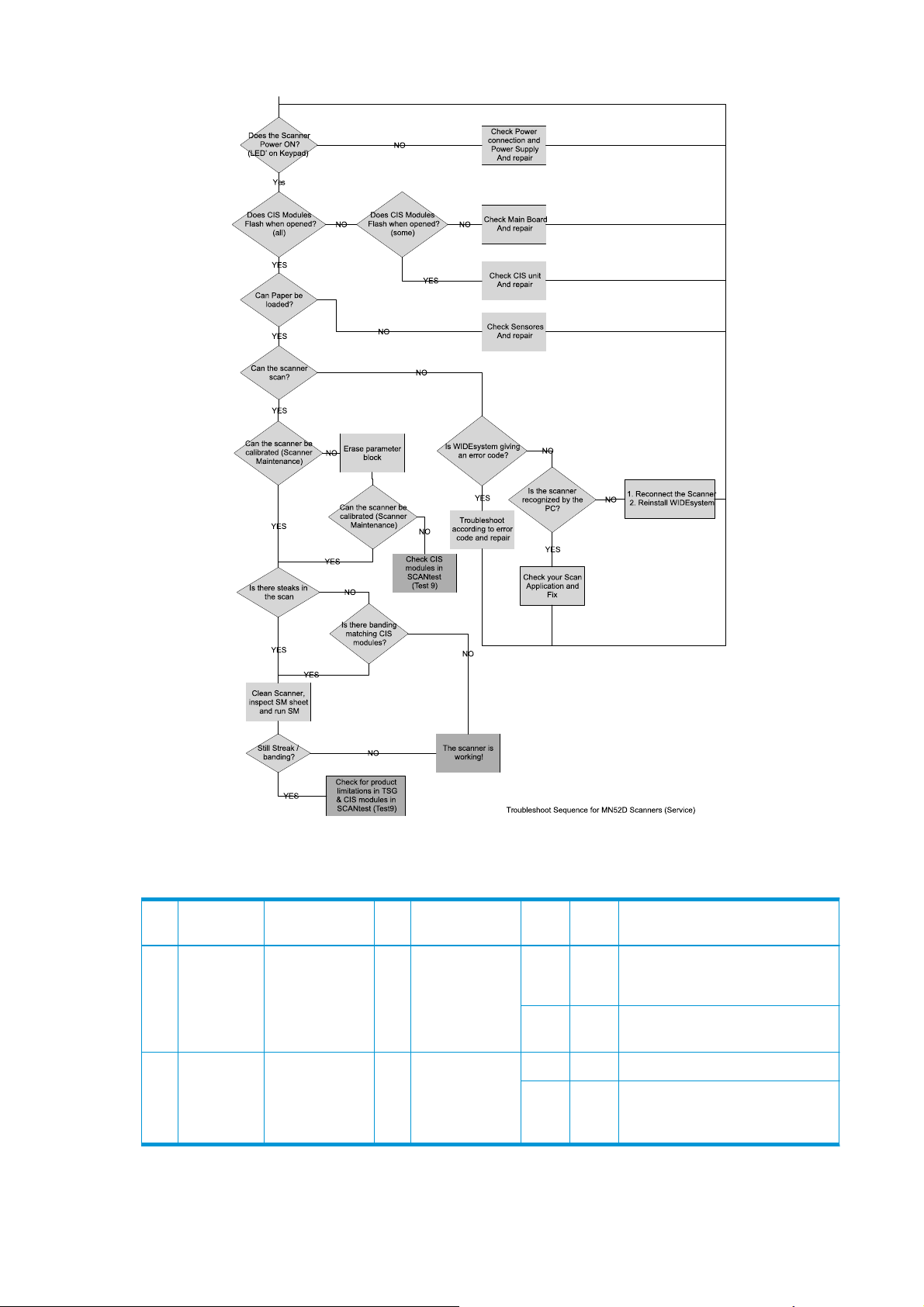
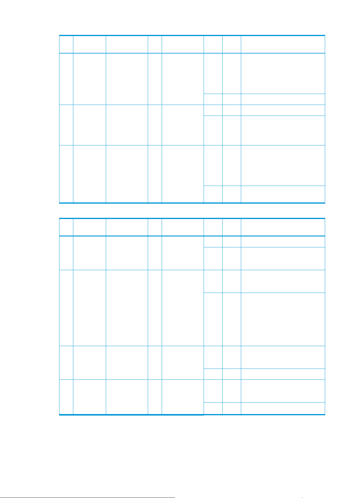
Troubleshooting print-quality and copy issues
P# Category Problem Q# Question Yes/NoC/T Solution
1 Copy problem The colors on one
side of the copy do
not correspond to
the colors on the
other side of the
copy
2Have you
1 Have you cleaned
and calibrated
your scanner
recently?
upgraded the
system software
to the latest
version?
No C CIS modules differences - The scanner
needs to be cleaned and calibrated (see
P25 and P25).
Yes See Q2
No C Upgrade system software
Yes T CIS unit might need replacement
8 Chapter 1 Troubleshooting ENWW
Page 17

P# Category Problem Q# Question Yes/NoC/T Solution
2 Copy problem I get thin lines of
wrong colors in my
copy
2Are the lines
3Are the lines
4 Do you have a
1Are the lines
vertical and also
present in your
preview?
horizontal and
equally spaced?
horizontal, but
irregular (maybe
only 1 line)?
great number of
regular spaced
lines very close to
each other and
restricted to one
side (1 camera)
only?
Yes C Erase the parameter block. Then clean
and calibrate the scanner (see P25 and
P25).
No See Q2
Yes C Check printheads by starting printhead
test on Printer. By using the built-in test
print function in the Designjet Scan Copy
application, you can also get an idea
whether the Printer is performing OK
No See Q3
Yes C The lines could be caused by a data
error. Upgrade system software
No See Q4
Yes T You might have a CIS element error.
Replace CIS unit
P# Category Problem Q# Question Yes/NoC/T Solution
3 Copy problem I get thick lines of
slightly wrong
colors in my copy
2Are the lines
P# Category Problem Q# Question Yes/NoC/T Solution
4 Copy problem Some colors are
not the same
when I compare
the master print
with the copy
2 Do you use the
1Are the lines
vertical and also
present in your
preview?
horizontal and
equally spaced?
1 Is the scanner
clean and
calibrated?
correct media
profile for the
actual media?
Yes C The scanner needs to be cleaned and
calibrated (see P25 and P25).
No See Q2
Yes C Check printheads by starting printhead
test on Printer. By using the built-in test
print function in the Designjet Scan Copy
application, you can also get an idea
whether the Printer is performing OK
No See P2.
No C See P1. Clean and calibrate the scanner
(see P25 and P25).
Yes See Q2
No C If you are using e.g. Glossy Media for
this copy, the media profile selected
should also be for Glossy Media.
Yes See Q3
3Is the media
profile valid?
No C Create a new media profile (see P26)
Yes See Q4
ENWW Troubleshooting print-quality and copy issues 9
Page 18

P# Category Problem Q# Question Yes/NoC/T Solution
4 Is the option 'Ink
5Is the media you
P# Category Problem Q# Question Yes/NoC/T Solution
5 Copy problem Only a part of the
master print is
being copied
No See Q3
2 Is the length too
Printer Original'
set in accordance
with your original?
are printing on the
same type as the
original?
1 Have you selected
'Auto size'?
short and the
width OK?
No C If original was printed using an Inkjet
Printer, set this option (see P27)
Yes See Q5
No C e.g. Use Glossy Media to reproduce a
Glossy original
Yes C Create a new media profile (see P26)
Yes C The scanner needs to be cleaned (see
P24)
Yes C The problem may be with the Printer
(not able to print close to the edges) or
Panel PC (Hard Disk is full).
No C Check that the margins that are set are
not too big. Also check Scanner Media
Offsets
P# Category Problem Q# Question Yes/NoC/T Solution
6 Copy problem Which setting will
give me the best
result when
copying?
P# Category Problem Q# Question Yes/NoC/T Solution
7 Copy Problem Nesting feature is
not working
2Is the Hard Disk
- - - C See section about media profile (P4).
1 Is the correct
printer selected?
close to being full?
No C Select the correct Printer
Yes See Q2
Yes C Free up some space, or try to run a
No C Make sure that Nesting is set: Select:
Use copy quality best. Choose the
correct Type of original ("Map" for maps,
"Photo" for photos, etc). Eventually go
to Original Setup to fine adjust colors
and sharpening. (See also online help
for more details - button with "?"
symbol)
nesting job with only 2 or 3 small
pictures. If that works, see P27.
Output Layout Nesting optimized
10 Chapter 1 Troubleshooting ENWW
Page 19

P# Category Problem Q# Question Yes/NoC/T Solution
8 Copy problem The Collate Copy
function does not
work
P# Category Problem Q# Question Yes/NoC/T Solution
9 Copy problem The lines are not
accurate
2Are the lines not
3Are the lines
1Is your Hard Disk
close to full?
1Are the lines wavy
and irregular?
sharp?
broken and the
errors situated in a
vertical column
between 2
columns?
Yes C Free up some space, or try to run a
collate job with a smaller picture.
No C Follow the step by step instructions in
the online help under Collate Copy.
Yes C/T C: The original could be curled or
crumpled. Try to flattten the original (in
case of very irregular waves there could
be a mechanical problem with the
scanner).
T: check motor and belt drive tension
No See Q2
Yes C/T C: Are you using the correct copy
method? Try sharpening.
No See Q3
Yes C You might have a visible stitching error
(see P28).
No C Check the dpi. In the case of too low
resolution, jagged diagonal lines will
appear.
P# Category Problem Q# Question Yes/NoC/T Solution
10 Copy Problem One side of the
preview is black
1Have you
upgraded the
system software
to the latest
version?
No C Upgrade system software.
Yes T Most likely a CIS module error. Replace
Troubleshooting general scanner issues
P# Category Problem Q# Question Yes/NoC/T Solution
12 System Error What should I do
when the program
hangs?
1 Are you running a
copy job?
Yes C Making a copy takes a lot of resources
No Restart the system. If the problem
the CIS unit.
according to the settings. Wait till the
copy is done before performing another
action.
comes back, reinstall the system.
ENWW Troubleshooting general scanner issues 11
Page 20

P# Category Problem Q# Question Yes/NoC/T Solution
13 File problem When I scan to file,
the file is very big
2 Are you scanning
P# Category Problem Q# Question Yes/NoC/T Solution
1 Are you scanning
in color?
in gray tones?
Yes C Scanning large drawings will generate
very big files. An A0 color drawing
scanned at 300 dpi will generate a file
size of approx. three Gigabytes when
scanned in an uncompressed format. In
order to reduce file size, select TIFF pack bits as format. You can reduce size
even more by selecting JPEG format, but
this format will reduce picture quality.
No See Q2
Yes C Scanning large drawings will generate
big files. An A0 gray tone drawing
scanned at 300 dpi will generate a file
size of approx. 300 Mbytes when
scanned in an uncompressed format. In
order to reduce file size, select TIFF pack bits as format. You can reduce size
even more by selecting JPEG format, but
this format will reduce picture quality.
No In order to reduce file size on scanned B/
W drawings, select TIFF group 4
compression.
14 File problem When I scan to file
P# Category Problem Q# Question Yes/NoC/T Solution
15 Network
Problem
P# Category Problem Q# Question Yes/NoC/T Solution
16 Scan to
network
my application
cannot read the
file
I cannot access the
system from the
network
I cannot access
network drivers
1Did you get an
error message
when creating the
file?
1Is the PC
connected to the
network?
1 With the Panel PC
connected to the
LAN, can you
access the Panel
PC from another
computer on the
network?
Yes C Check that you have enough disk space
and scan to file again, choosing TIFF
uncompressed as format
No C We only recommend to use the built-in
viewer for file viewing. Large format
drawing files may not load correctly in
other viewers due to file size. Try to
scan a smaller original (A4).
Yes C Do basic network troubleshooting.
No C Connect the PC to the Network.
Yes C Go to Q2
No C Check the network performance and
connection to the scanner Panel PC.
12 Chapter 1 Troubleshooting ENWW
Page 21
P# Category Problem Q# Question Yes/NoC/T Solution
2 Is the folder of the
server you are
trying to map
already mapped
by another user in
the Panel PC?
3 Do you have
permission to
access and write
to the network
folder you are
trying to map?
4Are you using the
correct user name
and password?
P# Category Problem Q# Question Yes/NoC/T Solution
Yes C Windows does not allow the same
server to be mapped by two different
users on one computer. Use the access
connection previously mapped or delete
the connection and map a new access
connection.
No C Go to Q3
Yes C Go to Q4
No C You cannot access this network folder.
Select a network folder for which you
have read and write permissions.
Yes C Try to map the network file from
another computer by selecting Windows
Explorer, Tools, Map network drive. If
you are able to map the drive in this
manner, you should also be able to map
through the Panel PC.
No C Use the correct user name and
password.
18 Scanner
Calibration
Problem
2 Error: Basic
3 Error: Sheet not
4Have you
Scanner
Calibration did not
succeed
1 Did any error occur
when performing
the Scanner?
calibration was
performed. but
failed to stitch
scanner or Could
not find
horizontal line or
Could not read
bar lines or Could
not recognize the
scanned IT8
picture.
recognized.
upgraded the
system software
to the latest
version?
Yes C See Q2
No C Clean and then run the scanner again
(see P24 and P 25). If that does not help,
see Q5.
Yes C Clean and then run the scanner again
(see P24 and P 25). If that does not help,
see Q5.
No See Q3.
Yes C Reinsert calibration sheet correctly and
run the scanner again. If that does not
help, see Q5.
No See Q4.
No C Upgrade system software. Clean the
scanner and then run Scanner
Maintenance again (see P24 and P 25).
Yes T Check the CIS modules.
ENWW Troubleshooting general scanner issues 13
Page 22

P# Category Problem Q# Question Yes/NoC/T Solution
19 System error I cannot install my
application on the
system.
P# Category Problem Q# Question Yes/NoC/T Solution
20 Updating How do I update
P# Category Problem Q# Question Yes/NoC/T Solution
21 Start-up
Problem
the system?
The system does
not power up
- - - C The copy system is only meant to
handle the factory installed software
and applications.
- - - C Download the new system file from the
1 Is the system dead
(no LEDs are lit,
the Panel PC
screen is black,
and no fan-noise
can be heard)?
Yes C 1. Check that all power switches on
the HP Support web site and copy into a
USB drive. Go to System Options >
Advanced > Update software, and follow
the instructions.
the equipment are ON.
2. Check if there is power at the wall
outlet.
3. Check power cables between wall
outlet and the individual units.
2 Does Panel PC
start with the
normal initial
screen?
3 Does Panel PC
start normally, but
the software does
not work?
4Is the Panel PC
dead (no fan noise
can be heard and
no screen image
appears)?
5 Is the Scanner
dead (no fan noise
can be heard and
no LEDs are lit)?
6 Does the scanner
hangup with all
LEDs lit?
No See Q2.
Yes C See Q5.
No See Q3.
Yes C Reinstall system software
No See Q4
Yes T Troubleshoot the Panel PC.
No See Q5.
No See Q6.
Yes T Check, and if necessary replace:
1. Power Supply Unit
2. Scanner controller board
Yes T Try the following:
1. Erase parameter block
2. Update the system software
3. Replace the Scanner controller
Board
No See P23.
14 Chapter 1 Troubleshooting ENWW
Page 23

P# Category Problem Q# Question Yes/NoC/T Solution
22 Mechanical
Problem
2 Can paper be
3 Does the Ready
P# Category Problem Q# Question Yes/NoC/T Solution
I cannot load the
original
1 Please try to load
a new piece of A4
paper at the
center of the
scanner. Does this
paper load?
loaded by pressing
the "Forward" key?
LED turn ON when
activating Original
Sensor (insert
paper)?
Yes C You have a problem with your original.
Please check that paper edges are not
bent or curled in any way.
No See Q2.
Yes C See Q3.
No T Try replacing the following:
1. Power Supply Unit
2. Feed motor (Stepper motor)
3. Scanner Controller Board
No T Check, and if necessary replace:
1. Paper/lid sensors
2. Scanner Controller Board
Yes C Check the settings in the software for
media loading.
23 Error code I get an Error
Code, what do I
do?
1Have you
P# Category Problem Q# Question Yes/NoC/T Solution
23a Error Code I still get an error
code, what do I
do?
"No scanner
found"
- - - - Re-power the system, and check if the
upgraded the
system software
to the latest
version?
Does the
Diagnostic LED
(and, in some
cases also other
LEDs) blink?
1 Does the scanner
start normally?
2 Are the interface
cables (Ethernet)
properly
connected to the
scanner and the
Panel PC?
No C Upgrade the system software. Check if
Yes C Lower Guide Plate to Normal position,
No C See P23.
Yes C See Q2.
Yes C See Q3.
error code reappears. If it does, see Q1.
Error Codes reappears. If it does, see
system errors list in chapter 2.
start Preview Scan to obtain an Error
Code or check if WIDEsystem gives an
Error Code. If it does, see system errors
list in chapter 2.
3Have you
upgraded your
system software?
Yes T 1. Replace network cable
2. Replace Scanner Controller Board
ENWW Troubleshooting general scanner issues 15
Page 24

P# Category Problem Q# Question Yes/NoC/T Solution
24 Cleaning How do I clean the
scanner?
P# Category Problem Q# Question Yes/NoC/T Solution
25 Color
Calibration
P# Category Problem Q# Question Yes/NoC/T Solution
26 Media
Validation
How do I color
calibrate the
scanner?
What is media
validation? How
do I validate?
- - - C Clean the Glass Plate on both sides with
mild detergent, and wipe thoroughly
with a lint-free cloth until dry. Check for
scratches. Deep scratches on the glass
plate or pressure rollers means
replacement of the part.
1 Do you have the
correct and "as
new" scanner
maintenance
sheet for the
scanner?
—— - C If the validate feature is chosen, a new
Yes C Clean scanner (see P24). Insert the
scanner maintenance sheet. Start
scanner calibration. The process is
automatic and will also include
stitching.
No C Get Correct/New Scanner Maintenance
Sheet.
color patch sheet is printed and can be
scanned for validation. In this way it can
be determined whether the produced
color map has passed.
P# Category Problem Q# Question Yes/NoC/T Solution
27 Ink Printer
Original
P# Category Problem Q# Question Yes/NoC/T Solution
28 Visible
stitching
Errors
What is Ink Printer
Original?
What is a visible
stitching error?
- — - C When the original has been printed on
an Inkjet printer this option should be
enabled.
- - - C A visible stitching error appears
typically as a column of broken lines
between 2 CIS modules. Normally it can
be solved by running Scanner
Calibration, which will perform an
automatic stitching adjustment. With
some curled or creased/crumpled
originals it is necessary to straighten
out the original to prevent it from lifting
from the glass plate.
16 Chapter 1 Troubleshooting ENWW
Page 25

Troubleshooting Specific Scanner Issues
P# Category Problem Q# Question Yes/NoC/T Solution
29 Vertical lines
(possible dust
problem)
P# Category Problem Q# Question Yes/NoC/T Solution
30 Firmware You are receiving
P# Category Problem Q# Question Yes/NoC/T Solution
31 Stepper
Motor
The image has a
vertical, white or
black line, which
could be caused by
dust. To verify
that the line is
caused by dust,
preview the image
and inspect the
preview using the
viewing section
buttons.
firmware-related
errors.
The Stepper Motor
does not work.
- - - C Perform Scanner Maintenance: Cleaning
and Scanner Calibration. Using Test 20
from Service Tools may help to identify
dusty/ dirty areas.
- - - C Try upgrading the System Software.
- - - C Try the following:
1. Use Test 6: Motor Test to check
the functionality of the Stepper
Motor.
2. Replace the Stepper Motor.
3. Replace the scanner controller
board.
P# Category Problem Q# Question Yes/NoC/T Solution
32 CIS unit The CIS modules
do not work
1Are some CIS
modules working
when opening the
scanner cover?
Yes - Replace CIS unit.
No - If none of the CIS modules work when
opening the scanner cover, replace
scanner controller board.
ENWW Troubleshooting Specific Scanner Issues 17
Page 26

P# Category Problem Q# Question Yes/NoC/T Solution
33 Skewing There is a skewing
problem
P# Category Problem Q# Question Yes/NoC/T Solution
34 Media
Loading
The media cannot
be loaded or there
are other media
loading problems.
- - - C Try the following:
1. Ensure that the Scanner Cover is
closed and latched.
2. Clean the rollers with isopropyl
alcohol.
3. Check the rollers.
4. Replace the CIS unit.
- - - C Try the following:
1. Check the Original Sensor (green
LED when loading media), or use
Test 46: Paper Sensor Test to
check the functionality of the
sensor.
2. Use Test 6: Motor Test to check
the functionality of the Stepper
Motor.
P# Category Problem Q# Question Yes/NoC/T Solution
36 Software You are
experiencing
problems with the
software
- - - C Try the following:
1. Reload the software.
2. After reloading the software, set-
up the system on the network
again (if necessary).
3. If the problems persist, reinstall
the software, and delete the user’s
files (press F12).
18 Chapter 1 Troubleshooting ENWW
Page 27

P# Category Problem Q# Question Yes/NoC/T Solution
37 Firmware All of the LEDs in
the scanner’s front
panel are flashing
when you turn on
the scanner (as
shown in the
image below),
indicating that
printer firmware
needs to be
upgraded.
NOTE: This
describes a
different situation
than when the
scanner is turned
on in special boot
mode, in which the
LEDs also flash.
- - - The most probable reason for this
Most common Image Quality issues
Banding Problems
Bad/no gray balance calibration (CIS module to module match).
situation is that the last system
software upgrade attempt was not
successful. To remedy this situation,
upgrade the system software.
Image Quality Problems
Scanning originals on a CIS scanner, that then have folds or are crumpled, is often perceived as a scanner
defect. In reality the defect is a technology limitation due to the original's very short distance from sensor to
surface, also called “Focal Length”. We also have a very short “Focus Depth”, meaning, if the original is NOT
in contact with the glass plate, it is very likely to be out of focus.
Dust Problems
There are image quality problems that are not related to hardware errors. These could be due to either
insufficient cleaning, bad calibration, or limitations in the CIS technology.
Streaks running in the scan direction which seem to appear and disappear during the scan are most likely
caused by dust. Clean the scanner and the original. The streaks are often a darker shade of color.
Streaks that run in the scan direction, that are color dependent or a lighter shade, are often calibration
related. Dust that was present in the scanner during calibration, but has been cleaned away since.
ENWW Most common Image Quality issues 19
Page 28

Stitching Problems
Other issues could be that the scanner simply needs to be calibrated, either because the parameter block has
been erased, never been calibrated, or that the scanner has been moved.
Cleaning the Scanning Area
The following parts must be cleaned using a soft lint-free cloth and a mild, streak-free, cleaning detergent.
Alternatively, the parts may be cleaned without the use of cleaning detergents by using a damp micro-fibre
cleaning cloth (soak the cloth with water and wring until damp):
●
Main scanner cover. Clean the main scanner cover to ensure that no dust is introduced into the scanning
area when you scan an original.
●
White pressure rollers
●
The Glass Plate. Do not recommend that customers clean the underside of the glass plate; it should only
be cleaned by an HP support technician.
●
The Feed Rollers. These may be cleaned with a damp micro-fibre cleaning cloth.
Once all these procedures have been completed, the scanner will be ready to work correctly.
The Cleaning Procedure
When cleaning any part of the scanning area DO NOT use abrasives, acetone, benzene or fluids that contain
these chemicals. Do not spray liquids directly onto the scanner glass plate or anywhere else in the scanner.
1. Turn the scanner power off.
2. Disconnect the scanner power cable.
20 Chapter 1 Troubleshooting ENWW
Page 29

3. Open the Guide Plate by pushing the left and right locking levers inwards, and flipping upwards to
expose the scan area.
4. Gently wipe the Glass Plate. Clean the glass with a lint-free cloth and a mild, streak-free, glass cleaner.
5. Dry the glass completely using a separate clean, dry lint-free cloth like the one provided with the
maintenance kit.
6. Clean the white pressure rollers. Wipe the white metal area with a lint-free cloth and a mild, streak-free,
glass cleaner.
ENWW Cleaning the Scanning Area 21
Page 30

7. Clean the platen rollers. Wipe the rollers with a lint-free cloth and a mild, streak-free, glass cleaner.
8. Dry the platen and rollers completely using a separate clean, dry lint-free cloth.
9. Close the Guide Plate.
10. Use the dust sheet to protect the Scanner when not in use.
CAUTION: Ensure that the scanner is turned off before covering it with the dust sheet. The scanner
will overheat if covered while turned on.
Troubleshooting Specific Panel PC Problems
●
Power failure
22 Chapter 1 Troubleshooting ENWW
Page 31

●
Boot up fails
●
LCD fails
●
No backlight and no display
●
With backlight but no display
●
The HDD fails
●
DDR DRAM fails
The following section is related to the PanelPC and it’s related components.
Power failure
If the power has been turned on, and there is no message on the screen, try the following:
●
Make sure the power cord is correctly connected.
●
Plug the power cord to another power outlet.
●
The system fan should start up if there is power in the PanelPC. If not, replace the External Power
Supply.
Boot up fails
LCD fails
The PanelPC issues a series of beeps which can be used to identify which part is failing.
●
One short beep: No error during POST (Power on Self-Test).
●
One long beep followed by two short beeps: Video initial error.
●
One long beep followed by nine short beeps: BIOS Bootblock error.
●
Single long beep repeatedly: DRAM error.
The failure of the LCD display can be divided into two issuses, the PanelPC has no backlight and no display, or
the Panel PC has the backlight but there is no display. Use the two troubleshooting flow charts to solve the
problem:
ENWW Troubleshooting Specific Panel PC Problems 23
Page 32

No backlight and no display
With backlight but no display
The HDD fails
The HDD is running, and the system configuration has identified the HDD’s ID while booting up. Try the
following:
24 Chapter 1 Troubleshooting ENWW
Page 33

●
Set the type of hard disk to AUTO in STANDARD CMOS SETUP.
●
Reconnect the cable between HDD and main board.
●
Change the HDD.
The HDD is not running, and the system configuration can not identify the HDD’s ID while booting up. Try the
following:
●
Reconnect the cable between HDD and main board.
●
Change the cable between HDD and main board.
●
Change the HDD.
DDR DRAM fails
If the computer repeatedly makes a long beep, and the display is blank when you power on, this indicates a
DDR DRAM error, replace the DDR DRAM.
ENWW Troubleshooting Specific Panel PC Problems 25
Page 34

Touch screen fails
Follow the steps in the flowchart below to quickly check if the touch screen fails:
Touch screen is working but can’t control the cursor
Try the following:
●
Run the calibration program.
●
Check that the cable between the LCD controller and the LCD is connected in the correct position.
●
Replace the LCD controller.
●
Replace the LCD.
Upgrade Scanner Software
Upgrade the HD Pro Scanner system software
System software on the web is divided in 5 packages to facilitate the download:
1. Download all 5 files (1 to 5) from
them to the same folder on your computer.
2. Extract part1; all of the parts extract one after the other to the selected folder.
3. After, the full System SW is located in the folder previously selected. The file size should be 3.32GB and
the extension is ".sif".
http://www.hp.com/go/designjethdproscanner/software. Save all of
4. Copy the System SW to a standard USB flash drive, formatted as FAT32,
26 Chapter 1 Troubleshooting ENWW
Page 35

5. Insert the USB drive into the PPC USB port.
6. Start the software update process as shown below:
ENWW Upgrade Scanner Software 27
Page 36

2 System Error Codes
●
System Error Codes for the Scanner Only on page 29
●
Error Codes for the JetImage Software RIP on page 36
●
Error Messages for the Touch Screen on page 40
28 Chapter 2 System Error Codes ENWW
Page 37

System Error Codes for the Scanner Only
Introduction
The following pages contain a list of system error codes and their respective descriptions and recommended
corrective actions. Only try one recommended action at a time and check if the error code has disappeared.
If you have an error code which is not documented in this Service Manual or you have an error which you
cannot resolve, then report the error to the HP Response Center or the nearest HP Support Office. When
reporting the error, have the following information ready:
●
Model and Serial Number of the scanner.
●
Which firmware revision the printer and the scanner is using.
●
SW version.
●
The complete error number.
●
ScanDump of Light Profiles.
Error Codes displayed on the Keypad
An error condition is indicated by a flashing Diagnostic Indicator. The error may be identified by an Error Code
Number being displayed on the screen and/or by the following combinations of flashing (F) indicators on the
Operator Panel: See
codes that follow after for details.
Flash Code Diagnostic Paper
BOOT F F
ERR_GENERAL F OFF
ERR_SU F F
ERR_CB F 2 X F
ERR_SMC F 5 X F
1 X F, 2 X F, means that the Paper Indicator flashes 1, 2, times every time the Diacnostic Indicator is turned
on. F, F, means that both indicators are flashing simultaneously.
The Software Modules
The first set of numbers in the error code refer to a part of the Scanner software or the Scanner.
The Software Modules on page 29 for an overview, and the lists of individual error
ENWW System Error Codes for the Scanner Only 29
Page 38

Software Modules Comments/Notes
51 - Scanner API Low level scanner control library. All scanner communication goes
52 - Image Format Library Printer and file formatting. All printing and file read/write is formatted/
53 - Copy Engine The central processing engine in the (JETimage) software.
54 - Closed Loop Calibration Color Management math library that calculates the media profiles.
55 - Test Software Scanner Maintenance / SCANtest.
56 - Jetimage container All user interface and business logic except for Scanner Maintenance /
57 - WIDEsystem (WS) Scanner surveillance utility
100 - Scanner Mechanical part of the Scanner.
Software Related Errors
System Error: 100-00119
Description:
Invalid SCSI command.
though this API.
decoded by this library.
SCANtest and WIDEsystem.
Corrective Action:
1. PC (cable, PC hardware/software etc.)
2. Update system software
System Error: 100-00120
Description:
Invalid value in SCSI CDB.
Corrective Action:
1. PC (cable, PC hardware/software etc.)
2. Update system software
System Error: 100-00121
Description:
Invalid SCSI parameter list length.
Corrective Action:
1. PC (cable, PC hardware/software etc.)
2. Update system software
System Error: 100-00123
Description:
30 Chapter 2 System Error Codes ENWW
Page 39

Unsupported SCSI parameter.
Corrective Action:
1. PC (cable, PC hardware/software etc.)
2. Update system software
System Error: 100-00124
Description:
Invalid SCSI parameter value.
Corrective Action:
1. PC (cable, PC hardware/software etc.)
2. Update system software
System Error: 100-00125
Description:
Incorrect scanner status. Please check the paper path and reload the media.
Corrective Action:
1. PC (cable, PC hardware/software etc.)
2. Update system software
System Error: 100-00126
Description:
SCSI time-out.
Corrective Action:
1. PC (cable, PC hardware/software etc.)
2. Update system software
System Error: 100-00127
Description:
The scanner keyboard was used during communication with the scanner.
Corrective Action:
▲
User interaction
System Error: 100-00128
Description:
The scanner has paper jam. Please reload the media.
ENWW Software Related Errors 31
Page 40

Corrective Action:
1. User interaction
2. Related mechanical parts
3. Lamp and Motor driver board
4. Switch Mode Power Supply
5. Main controller board
System Error: 100-00129
Description:
The scanner does not support this test command in normal mode. Please restart test program.
Corrective Action:
▲
User interaction
System Error: 100-00131
Description:
The scanner is initializing. Please retry the operation when the scanner has finished initializing.
Corrective Action:
▲
User interaction
System Error: 100-00132
Description:
The scanner is warming up. Please retry the operation when the scanner has finished warming up.
Corrective Action:
▲
User interaction
System Error: 100-50122
Description:
Pop request failed, position unknown.
Corrective Action:
1. PC (cable, PC hardware/software etc.)
2. Update system software
System Error: 100-50123
Description:
Pop request failed, invalid command.
32 Chapter 2 System Error Codes ENWW
Page 41

Corrective Action:
1. PC (cable, PC hardware/software etc.)
2. Update system software
System Error: 100-50218
Description:
Data never arrives in the Image.
Corrective Action:
▲
Update system software
System Error: 100-50231
Description:
System software download is in progress.
Corrective Action:
▲
Update system software
System Error: 100-50232
Description:
System software is incomplete. Please download new system software.
Corrective Action:
▲
User interaction
System Error: 100-50234
Description:
Scanner is in safe mode. Please reboot scanner or download new system software.
Corrective Action:
1. User interaction
2. Main controller board
System Error: 100-50237
Description:
Host PC does not support SSE2 calculations.
Corrective Action:
▲
User interaction
System Error: 100-50259
Description:
System software unable to identify controller board id.
ENWW Software Related Errors 33
Page 42

Corrective Action:
▲
Main controller board
System Error: 100-50260
Description:
System software unable to identify controller board variant.
Corrective Action:
▲
Main controller board
System Error: 100-50268
Description:
ETH PHY loopback error.
Corrective Action:
▲
Main controller board
System Error: 100-50269
Description:
Flash error.
Corrective Action:
▲
Main controller board
System Error: 100-50270
Description:
RAM error.
Corrective Action:
▲
Main controller board
System Error: 100-50271
Description:
Scanner has no MAC address.
Corrective Action:
▲
Main controller board
System Error: 100-50600
Description:
Main controller board error.
34 Chapter 2 System Error Codes ENWW
Page 43

Corrective Action:
1. Main controller board
2. Switch Mode Power Supply
System Error: 100-50601
Description:
CIS unit error.
Corrective Action:
1. CIS Unit
2. Main controller board
System Error: 100-50602
Description:
System software error. Please download latest system software.
Corrective Action:
1. Update system software
2. Main controller board
System Error: 100-50603
Description:
Unrecoverable scanner state. Please reboot the scanner. Download of the latest system software and PC
application/driver may be required.
Corrective Action:
1. Reboot scanner
2. Update system software
3. PC driver/software
ENWW Software Related Errors 35
Page 44

Error Codes for the JetImage Software RIP
-13 Unable to rename the folder.
Cause Solution
Unable to rename the folder. Occurs during file browsing operations, usually due to a share
-12 Unable to delete the folder.
Cause Solution
Unable to delete the folder (occurs during file browsing
operations, typically if a folder is shared).
-11 The folder must be empty.
Cause Solution
The folder must be empty (occurs during file browsing
operations).
-2 No media profile selected for current printer.
Cause Solution
No media profile selected for current printer. Prepare a Media Profile before performing the operation.
issue.
Close all the applications and try again.
Check that the folder is empty before deleting it.
-1 No printer selected.
Cause Solution
No printer selected. Select a printer. A printer must be configured in the application
02 Invalid scan coordinates. The paper frame was placed fully outside the scan image.
Cause Solution
Invalid scan coordinates. The paper frame was placed fully
outside the scan image.
06 Not enough disk space for spool file.
Cause Solution
Not enough disk space for spool file. Make sure that the environment TEMP (or secondary TMP) points
before trying to print.
Try repositioning the paper frame so that it covers some of the
scannable area.
to a folder with plenty of space.
36 Chapter 2 System Error Codes ENWW
Page 45

08 The scanner is currently on standby. Please press the soft power button on the scanner to activate it.
Cause Solution
The scanner is currently on standby. Press the soft Power button on the scanner to activate it.
00003 Scanning invalid size of area requested for scanning.
Cause Solution
Negative scan-width specified. Reselect the scan area and try again.
01003 Error printing colorsheet.
Cause Solution
Error printing colorsheet. Try the following:
●
Check the printer to make sure it is switched ON and
connected to the scanner.
●
Try printing a test print to make sure that the printer is
working.
01013 Error detecting index-mark.
Cause Solution
Skew: Error detecting the index mark. Try the following:
●
Try restarting the system.
●
If the problem persists, view the scandump.tif file for
further diagnosis.
01014 Sheet bad aligned.
Cause Solution
Sheet badly aligned. Try the following:
●
Reinsert the sheet, making sure that it is straight and at the
right position.
●
If the problem persists, view the scandump.tif file for
further diagnosis.
01015 Error detecting left margin.
Cause Solution
Error detecting the left margin of the sheet. Try the following:
●
Try reinserting the sheet.
●
If the problem persists, view the scandump.tif file for
further diagnosis.
ENWW Error Codes for the JetImage Software RIP 37
Page 46

01016 Error detecting right margin.
Cause Solution
Error detecting the right margin of the sheet. Try the following:
●
Try reinserting the sheet.
●
If the problem persists, view the scandump.tif file for
further diagnosis.
01017 Error reading colorsheet.
Cause Solution
Error reading the colorsheet. The end of the sheet is reached
before expected.
01018 CLC aborted.
Cause Solution
The Close Loop Calibration (CLC) has been aborted. The user has cancelled the color map operation.
01019 Wrong insert position.
Cause Solution
The sheet has been inserted in the wrong position. Try the following:
01020 Can’t find top of sheet.
Check that the correct colorsheet is being used.
●
Reinsert the sheet, making sure that it is at the right
position.
●
If the problem persists, view the scandump.tif file for
further diagnosis.
Cause Solution
The top of the sheet couldn’t be found. Reinsert the sheet, making sure that it is at the right position.
01021 Can’t find bottom of sheet.
Cause Solution
The bottom of the sheet couldn’t be found. Reinsert the sheet, making sure that it is at the right position.
02004 Unable to open device for reading.
Cause Solution
Unable to open the device for reading. Check that the device (file) is available.
38 Chapter 2 System Error Codes ENWW
Page 47

02005 Unable to open device for writing.
Cause Solution
Unable to open the device for writing. Check that the device (file or printer) is available.
02006 Unable to read from device.
Cause Solution
Unable to read from the device. Try the operation again.
02007 Unable to write to device.
Cause Solution
Unable to write to the device. Try the operation again.
02013 Destination already exists.
Cause Solution
Destination already exists. Try the operation again with a different file name.
03008 Device not available.
Cause Solution
Scanner not found. Try the following:
●
Check that the scanner is turned ON.
●
Check the connection to the scanner.
13496 The scanner is initializing or warming up.
Cause Solution
The scanner is initializing. This happens if you try to scan too quickly after powering ON the
17977 Media is present in scanner, but command was aborted by user.
Cause Solution
User interfered with the scanner. Try the operation again.
scanner. Wait a short while and then try scanning again.
17980 Paper jam.
Cause Solution
Paper jam. Check rollers and mechanical paper detectors for any paper jam.
Once paper jam is cleared, try the operation again.
ENWW Error Codes for the JetImage Software RIP 39
Page 48

Error Messages for the Touch Screen
BIOS ROM checksum error - system halted.
Cause Solution
Error during initialization. Reboot the system and enter the BIOS setting. Load Setup
CMOS battery failed.
Cause Solution
The battery life is approximately three years before it requires
replacement.
CMOS checksum error - defaults loaded.
Cause Solution
Error detected in the CMOS. Reboot the system and enter the BIOS setting. Load Setup
Display switch is set incorrectly
Cause Solution
Problem found with the Touch Screen. Connect the Touch Screen to a CRT Monitor and check the
Default and save the BIOS setting.
Replace the CMOS Battery.
Default and save the BIOS setting.
resolution setting for the display. If the CRT Monitor is working
well then it seems there is an LCD problem.
Hard Disk install failure.
Cause Solution
No Hard Disk detected, error related to Hard Disk Drive. Try the following:
●
In the BIOS setup select Standard CMOS Features and check
if the IDE/SATA detection method is set to AUTO (password
to access the BIOS is bigcoco)?
◦
If Yes: In Advanced BIOS features, set HDD to first boot
device.
◦
If No: Choose auto for all IDE/SATA detection.
●
Check if HDD can be detected in the boot-up system
configuration table:
◦
If Yes: check the boot up files in HDD, recover it if
necessary.
◦
If No: replace HDD.
40 Chapter 2 System Error Codes ENWW
Page 49

Primary master hard disk fail.
Cause Solution
No Hard Disk detected, error related to Hard Disk Drive. Try the following:
●
In the BIOS setup select Standard CMOS Features and check
if the IDE/SATA detection method is set to AUTO (password
to access the BIOS is bigcoco)?
◦
If Yes: In Advanced BIOS features, set HDD to first boot
device.
◦
If No: Choose auto for all IDE/SATA detection.
●
Check if HDD can be detected in the boot-up system
configuration table:
◦
If Yes: check the boot up files in HDD, recover it if
necessary.
◦
If No: replace HDD.
Secondary master hard disk fail.
Cause Solution
No Hard Disk detected, error related to Hard Disk Drive. Try the following:
●
In the BIOS setup select Standard CMOS Features and check
if the IDE/SATA detection method is set to AUTO (password
to access the BIOS is bigcoco)?
◦
If Yes: In Advanced BIOS features, set HDD to first boot
device.
◦
If No: Choose auto for all IDE/SATA detection.
●
Check if HDD can be detected in the boot-up system
configuration table:
◦
If Yes: check the boot up files in HDD, recover it if
necessary.
◦
If No: replace HDD.
Primary slave hard disk fail.
Cause Solution
No Hard Disk detected, error related to Hard Disk Drive. Try the following:
●
In the BIOS setup select Standard CMOS Features and check
if the IDE/SATA detection method is set to AUTO (password
to access the BIOS is bigcoco)?
◦
If Yes: In Advanced BIOS features, set HDD to first boot
device.
◦
If No: Choose auto for all IDE/SATA detection.
●
Check if HDD can be detected in the boot-up system
configuration table:
ENWW Error Messages for the Touch Screen 41
Page 50

Primary slave hard disk fail.
Cause Solution
◦
If Yes: check the boot up files in HDD, recover it if
necessary.
◦
If No: replace HDD.
Secondary slave hard disk fail.
Cause Solution
No Hard Disk detected, error related to Hard Disk Drive. Try the following:
●
In the BIOS setup select Standard CMOS Features and check
if the IDE/SATA detection method is set to AUTO (password
to access the BIOS is bigcoco)?
◦
If Yes: In Advanced BIOS features, set HDD to first boot
device.
◦
If No: Choose auto for all IDE/SATA detection.
●
Check if HDD can be detected in the boot-up system
configuration table:
◦
If Yes: check the boot up files in HDD, recover it if
necessary.
◦
If No: replace HDD.
Memory test fail.
Cause Solution
Memory test has failed. Try the following:
●
Re-install the SDRAM and check if the problem is solved:
◦
If Yes: There was a poor connection between the Main
Board and the SDRAM Memory Module.
◦
If No: Replace the SDRAM Memory Module.
42 Chapter 2 System Error Codes ENWW
Page 51

3 Parts and Diagrams
●
Scanner on page 44
●
Panel PC on page 45
ENWW 43
Page 52

Scanner
Number in photo Description HP Part Number
1-01 Left Side Cover G6H50-67009
1-02 Glass Plate CM719-60013
1-03 Paper/LID Sensor G6H51-67016
1-04 Pressure Rollers (6 pcs) G6H50-67008
1-05 Right Side Cover including operators panel G6H50-67013
2-01 Controller Board G6H50-67004
2-02 CIS Unit 44" except controller board G6H50-67005
3-01 Power Supply G6H50-67003
3-02 Optointerrupter (Tacho sensor, ATAC sensors) G6H51-67015
3-03 Stepper Motor Assembly G6H51-67010
3-04 Power Entry Module with EMI Filter G6H50-67006
3-05 Cable Interface G6H50-67012
3-06 Spring for CIS bridge G6H50-67011
N/A Paper guide (2 pcs) G6H50-67014
N/A Return Guide G6H50-67015
N/A Calibration Sheet G6H50-67002
N/A Castors G6H51-67026
N/A Europe Power Cord SV KIT CQ533-60001
N/A America Power Cord SV KIT CQ533-60002
N/A Asia Power Cord SV KIT CQ533-60003
44 Chapter 3 Parts and Diagrams ENWW
Page 53

Panel PC
HP Part Number Description Image
G6H51-67035 PPC Cable Harness
G6H51-67035 PPC Cable Harness
G6H51-67035 PPC Cable Harness
G6H51-67035 PPC Cable Harness
G6H51-67035 PPC Cable Harness
G6H51-67035 PPC Cable Harness
G6H51-67035 PPC Cable Harness
G6H51-67035 PPC Cable Harness
G6H51-67035 PPC Cable Harness
G6H51-67042 PPC External PSU
G6H51-67046 PPC Front Bezel Module
G6H51-67051 PPC Panel Module
G6H51-67048 Rear Cover
ENWW Panel PC 45
Page 54

G6H51-67047 PPC Motherboard cover
G6H51-67044 PPC Touch Screen Controller
G6H51-67049 PPC LED light board
G6H51-67041 PC Main Board
G6H51-67039 PPC HDD
G6H51-67043 PPC SDRAM
G6H51-67045 PPC Cooler module
46 Chapter 3 Parts and Diagrams ENWW
Page 55

4 Removal and Installation
●
Introduction
●
Safety Precautions
●
Electrostatic Discharge (ESD) Precautions
●
Required Tools
●
Open the CIS Unit
●
Scanner Controller Board
●
Right Side Cover
●
Power Supply
●
Left Side Cover
●
Stepper Motor Assembly
●
Tacho Sensor
●
Paper and Lid Sensors
●
Complete CIS Unit
●
Power Entry Module
●
Cable Interface
●
Spring for CIS Bridge
●
Pressure Rollers
ENWW 47
Page 56

Introduction
This chapter is a step-by-step guide to the removal and installation of the key components in the product.
You may find it useful to tick off the steps as they are performed. Use the illustration at each procedure to
identify the parts referred to in the text.
The procedures appear in order of removal. So the whole product can be stripped down by starting at the
beginning of this chapter and working through the subsequent procedures.
Safety Precautions
Review WARNING and CAUTION instructions before you service the product. Follow these warnings and
cautions for your protection and to avoid damaging the product.
NOTE: Serious shock hazard leading to death or injury may result if you do not take the following
precautions:
Ensure that the AC power outlet (mains) has a protective earth (ground) terminal.
Switch off the printer, the scanner, and the PC, and then disconnect them from the power source prior to
performing any maintenance.
Prevent water or other liquids from running onto electrical components or circuits, or through openings in
the module.
Electrostatic Discharge (ESD) Precautions
To prevent damage to the product circuits from high-voltage electrostatic discharge (ESD):
1. Do not wear clothing that is subject to static build-up.
2. Do not handle integrated circuits (ICs) in carpeted areas.
3. Do not remove an IC or a printed circuit assembly (PCA) from its conductive foam pad or conductive
packaging until you are ready to install it.
4. Ground (earth) your body while disassembling and working on the Scanner. This can be done by
touching any metallic part of the Scanner.
5. After removing a cover from the Scanner, attach an earthing (ground) lead between the PCA common
and earth ground. Touch all tools to earth ground to remove static charges before using them on the
Scanner.
6. After removing any PCA from the Scanner, place it on a conductive foam pad or into its conductive
packaging to prevent ESD damage to any ICs on the PCA.
Required Tools
The following Common Hand Tools are required to disassemble and repair the Scanner:
●
Torx 10 Straight
●
Torx 15 Straight & Angled
●
Torx 20 Straight & Angled
NOTE: Before replacing any electrical parts such as the Scanner Control Unit or CIS Unit, try calibrating the
scanner in order to get the scanner to recreate the content of the parameter block. This will solve the
problem in most cases.
48 Chapter 4 Removal and Installation ENWW
Page 57

Open the CIS Unit
1. Remove the screws (x2, Torx 15)
2. Remove the screws (x5, Torx 15).
3. Remove the cover from the CIS unit.
ENWW Open the CIS Unit 49
Page 58

Scanner Controller Board
Removal
Prerequisites: Turn off the scanner, disconnect the power cord, and
1. Disconnect the cables (A), release the lock (X) on the ribbon cables, and pull the cable out (B).
NOTE: If required; remove the screws on the wire bracket (C).
2. Remove the screws (x3, Torx 10):
Open the CIS Unit on page 49.
Installation
▲
Replace the Scanner Controller Board and reverse the removal steps.
50 Chapter 4 Removal and Installation ENWW
Page 59

Right Side Cover
Removal
Prerequisites: Turn off the scanner, disconnect the power cord, and
1. Remove the screws (x2, Torx 20).
2. Carefully remove the cover.
CAUTION: The keypad ribbon is attached to the cover.
3. Disconnect the keypad ribbon cable.
Open the CIS Unit on page 49.
4. Disconnect the keypad ribbon cable.
5. Pull the cable out though the side cover.
Installation
▲
Replace the Right Side Cover and reverse the removal steps.
ENWW Right Side Cover 51
Page 60

Power Supply
Removal
Prerequisites: Turn off the scanner, and disconnect the power cord.
CAUTION: The power supply is double pole/neutral fusing.
1. Remove the screws (x2, Torx 20).
2. Carefully remove the cover.
CAUTION: The keypad ribbon is attached to the cover.
3. Disconnect the keypad ribbon cable.
4. Disconnect the cables (x2).
5. Remove the screws (x4, Torx 10), and lift the Power Supply out.
Installation
52 Chapter 4 Removal and Installation ENWW
Page 61

▲
Replace the Power Supply and reverse the removal steps.
ENWW Power Supply 53
Page 62

Left Side Cover
Removal
1. Remove the screws (x2, Torx 20).
2. Remove the cover.
Installation
▲
Replace the Left Side Cover and replace the screws.
54 Chapter 4 Removal and Installation ENWW
Page 63

Stepper Motor Assembly
Removal
Prerequisites: Turn off the scanner, disconnect the power cord, and
1. Remove the
2. Disconnect the motor cable.
3. To release belt tension; loosen the screw (Torx 10) (don’t remove).
Right Side Cover on page 51.
Open the CIS Unit on page 49.
4. Push the tension wheel upwards, and tighten the screw again.
ENWW Stepper Motor Assembly 55
Page 64

5. Remove the screws (x2, Torx 20).
6. Remove the Stepper Motor Assembly.
Installation
▲
Replace the Stepper Motor Assembly, and reverse the removal steps.
56 Chapter 4 Removal and Installation ENWW
Page 65

Tacho Sensor
Removal
Prerequisites: Turn off the scanner, disconnect the power cord, and
1. Remove the
2. Disconnect the sensor cable.
3. Loosen, but don't remove, the Torx 10 screw (A). Hold in place with the 8mm wrench (B), and remove
the tacho wheel (C).
Right Side Cover on page 51.
Open the CIS Unit on page 49.
4. Gently push together the lock flaps, and remove sensor.
Installation
▲
Replace the Tacho Sensor, and reverse the removal steps.
ENWW Tacho Sensor 57
Page 66

Paper and Lid Sensors
Removal
Prerequisites: Turn off the scanner, disconnect the power cord, and
1. For Load and Paper sensor (A): Remove the screws (x4, Torx 10) and roller cover.
For Lid and Exit sensor (B):
the roller cover.
2. Disconnect the sensor cable (A), and remove the screw (x1,Torx 10) and Sensor (B).
Open the CIS Unit on page 49, remove the screws (x10, Torx15), and flip out
Open the CIS Unit on page 49.
Installation
▲
Replace the Sensor, and reverse the removal steps.
58 Chapter 4 Removal and Installation ENWW
Page 67

Complete CIS Unit
Removal
Prerequisites: Turn off the scanner, and disconnect the power cord. Remove the
on page 50 and the Right Side Cover on page 51.
1. Remove the grounding screws (A), un-clip the USB cable (B), and un-clip the Keypad cable (C).
2. Disconnect the cables (A), remove the screws and bracket (B), and guide the cables back into the CIS
unit.
Scanner Controller Board
3. Lift out the CIS unit by its top edge.
Installation
▲
Replace the CIS Unit, and reverse the removal steps. Run a full calibration on the scanner.
ENWW Complete CIS Unit 59
Page 68

Power Entry Module
Removal
Prerequisites: Turn off the scanner, and disconnect the power cord. Remove the
1. Remove the cables.
2. Push the lock flaps in on both sides (A), and push the module out though the back (B).
Right Side Cover on page 51.
Installation
▲
Replace the Power Entry Module, and reverse the removal steps.
60 Chapter 4 Removal and Installation ENWW
Page 69

Cable Interface
Removal
Prerequisites: Turn off the scanner, and disconnect the power cord. Remove the
on page 50 and the Right Side Cover on page 51.
1. Disconnect the USB cable (A), remove the grounding screw (B), and un-clip the cable from the CIS unit.
2. Remove the screw (x1, Torx 15) (A), and carefully pull the cable out of the CIS bridge.
Scanner Controller Board
3. Remove the clip by sliding it outwards (A), then push the USB connector and cable out though the back
(B).
Installation
▲
Replace the Cable Interface, and reverse the removal steps.
ENWW Cable Interface 61
Page 70

Spring for CIS Bridge
Removal
Prerequisites: Turn off the scanner, and disconnect the power cord. Remove the
on page 50 and the Left Side Cover on page 54.
1. Remove the Spring.
2. Loosen the screws to release the clamp (inside the CIS unit).
Scanner Controller Board
3. Remove the screws (x3, Torx 15) (A), and pull out the assembly (B).
Installation
▲
Replace the Assembly, and reverse the removal steps.
NOTE: Remember to tighten the clamp.
62 Chapter 4 Removal and Installation ENWW
Page 71

Pressure Rollers
Removal
Prerequisites: Turn off the scanner, disconnect the power cord, and
1. Remove the screws (x3, Torx 10) (A), and pull the Roller Cover sheet out through the back (B).
2. Carefully pull the Pressure Roller out (repeat for all 6).
Open the CIS Unit on page 49.
Installation
▲
Replace the Pressure Rollers, and reverse the removal steps.
NOTE: Remember to calibrate the scanner.
ENWW Pressure Rollers 63
 Loading...