

Page 1
x4
?
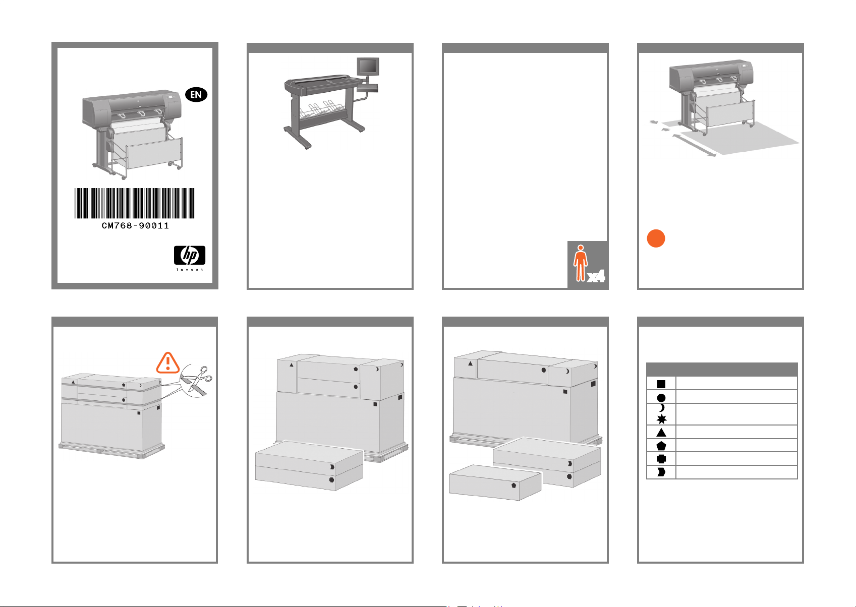
Read these instructions carefully...
What you will need for this procedure
- Some of the printer components are bulky,
you will need up to four people to lift them.
When this is necessary, the symbol shown at the
bottom is shown.
- To assemble the printer you will need at least
3 × 5 m (10 × 16 ft) of empty oor space, and
about four hours.
HP Designjet 4520 with Scanner: Reduce setup
time by assembling the scanner rst and switching
it on. The scanner takes an hour to warm up when
started for the rst time.
Printer working area
Before you start unpacking, consider where
you are going to put the assembled printer. You
should allow some clear space on all sides of
the printer box. The recommended clearances
are shown in the illustration above.
In case of difculty, please consult:
- Your printer’s Embedded Web Server
HP Designjet 4520/4520ps
Printer Assembly Instructions
Scanner (mfp only)
© 2009 Hewlett-Packard Company
Inkjet Commercial Division
Avenida Graells 501 · 08174
Sant Cugat del Vallès
Barcelona · Spain
All rights reserved
Printed in Germany · Imprimé en Allemagne · Stampato in Germania
10 cm
179 cm
1 2 3 4
Cut the strap around the boxes carefully, as the
boxes may fall as soon as the strap is cut.
Preliminary unpacking: Outside Europe
The shapes on the boxes identify the contents.
Shape Contents
Printer body
Stand and bin assembly
Consumables box, including…
Maintenance Kit (keep safe)
Spare box (used later)
Roll module
Scanner body (mfp only)
Scanner stand (mfp only)
Preliminary unpacking: Europe
Page 2
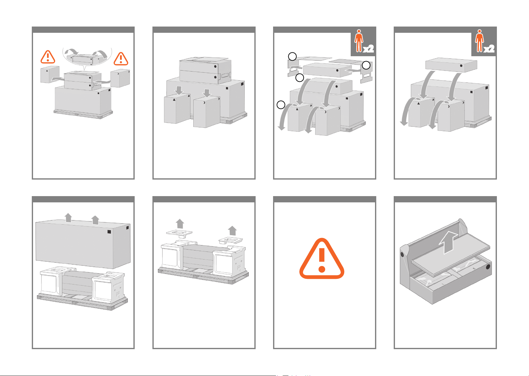
5 6 7 8
Remove the 2 lids. Lower the stand and bin box
onto the consumables and spare boxes. Then
lower the box onto the oor.
Place the consumables and spare boxes in front
of the printer body.
Lower the roll module box onto the consumables
and spare boxes. Then lower the box onto the
oor. Then remove the consumables and spare
boxes.
1
1
2
3
Fold up the two lids as shown, and remove the
consumables and spare boxes
x2 x2
9 10 11 12
Remove the rst tray containing the parts for
the bin.
Remove the main printer box. Remove the two packing pieces. When you are unpacking the stand assembly,
you will see that there is anti-slip material
around two of the wheels on the feet.
DO NOT REMOVE this material yet.
Page 3
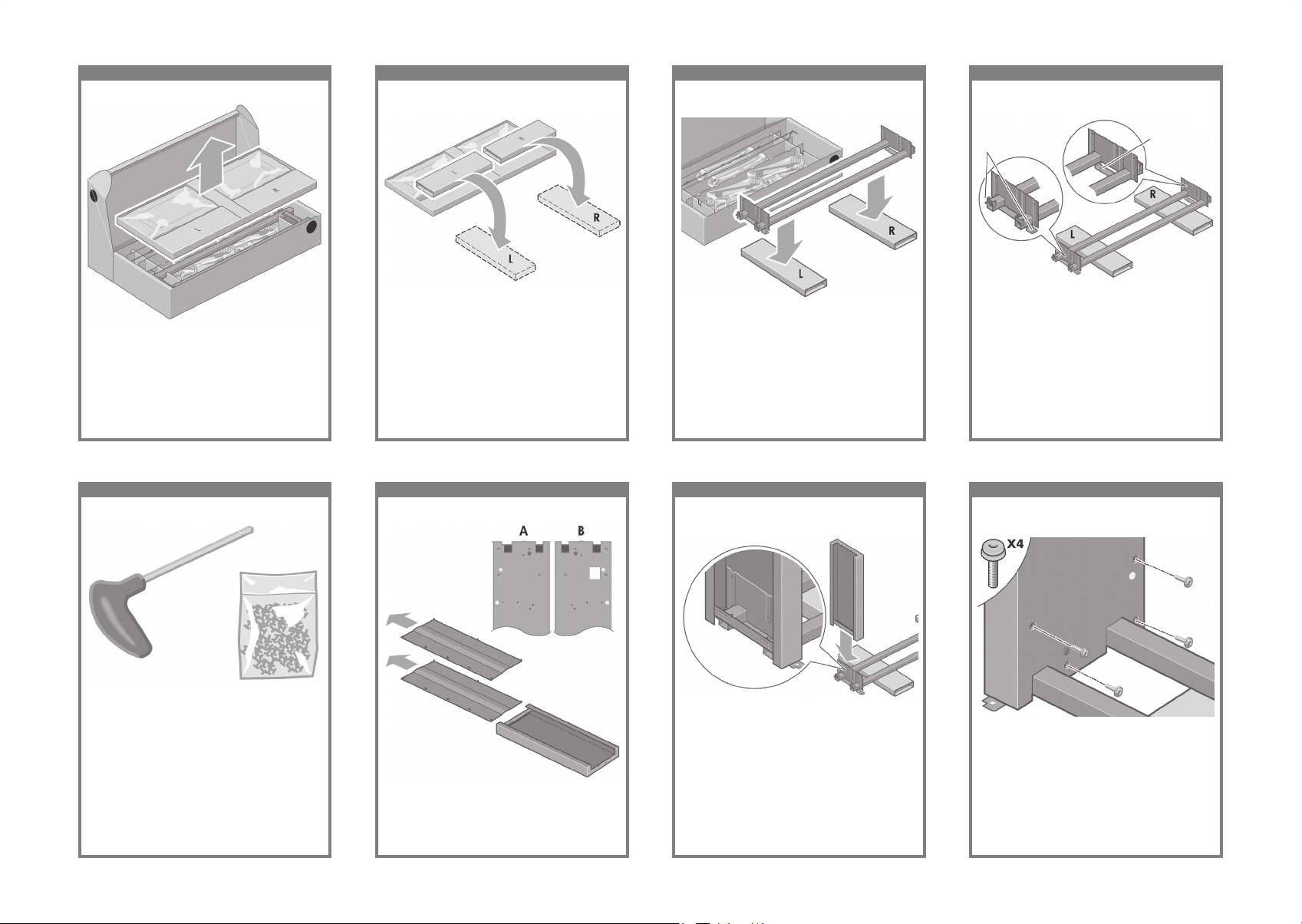
13 14 15 16
You now need to identify which is the left and
the right side of the cross-brace.
Remove the second tray from the stand and bin
assembly box. This tray contains the stand legs.
From the second tray, remove the two boxes
marked with L and R. Place them on the oor as
shown.
Lower the cross-brace on to the L and R boxes.
2 holes
Left
Right
1 hole
17 18 19 20
Fix the left leg to the cross-brace using four
screws on the inner side of the leg.
Now you will need the bag of screws and the
screwdriver provided. You may notice that the
screwdriver is slightly magnetic.
Identify the left leg (A) and the right leg (B) as
shown above. Remove the two leg covers from
the left leg.
Lower the left leg onto the left side of the cross-
brace. The left leg will t only on the left side of
the cross-brace.
Page 4
21 22 23 24
Fix the right leg to the cross-brace using two
screws on the outer side of the leg.
Fix the left leg to the cross-brace using two
screws on the outer side of the leg.
Lower the right leg onto the right side of the
cross-brace. The right leg will t only on the right
side of the cross-brace.
Fix the right leg to the cross-brace using four
screws on the inner side of the leg.
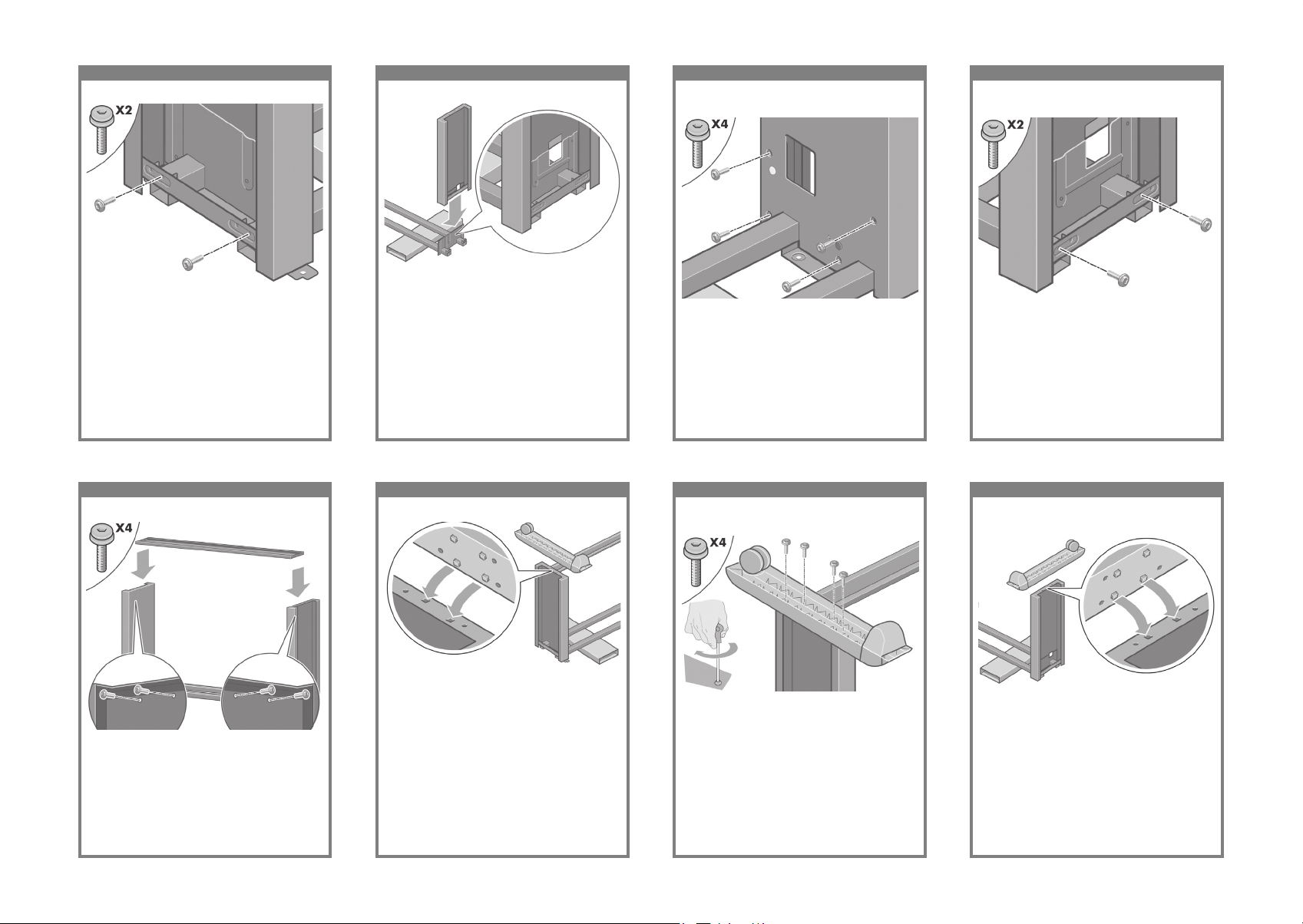
25 26 27 28
Position a foot on the right leg. There are pins
to help you to position the foot correctly. Do not
remove the anti-slip material from the wheel.
Fix the stand cross-bar using four screws. Position a foot on the left leg. There are pins to
help you to position the foot correctly. Do not
remove the anti-slip material from the wheel.
Fix the left foot using four screws.
Page 5
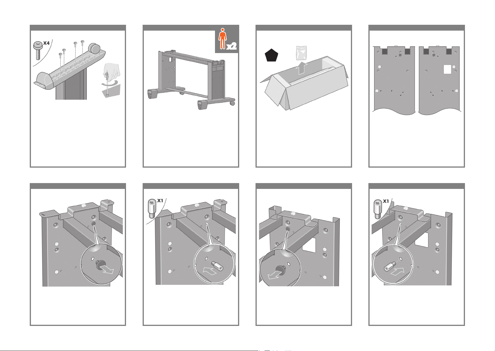
29 30 31 32
Please take note of the colored plugs located
on the legs.
Fix the right foot using four screws. Turn the stand assembly into an upright position
as shown above.
Open the box containing the roll module. Remove the plastic bag containing the screws.
x2
Left Leg/Lang 2
Lang 3/Lang 4
Right Leg/Lang 2
Lang 3/Lang 4
33 34 35 36
Locate the pin into the right leg.Remove the blue plug on the left leg. Locate the pin into the left leg. Remove the blue plug on the right leg.
Page 6
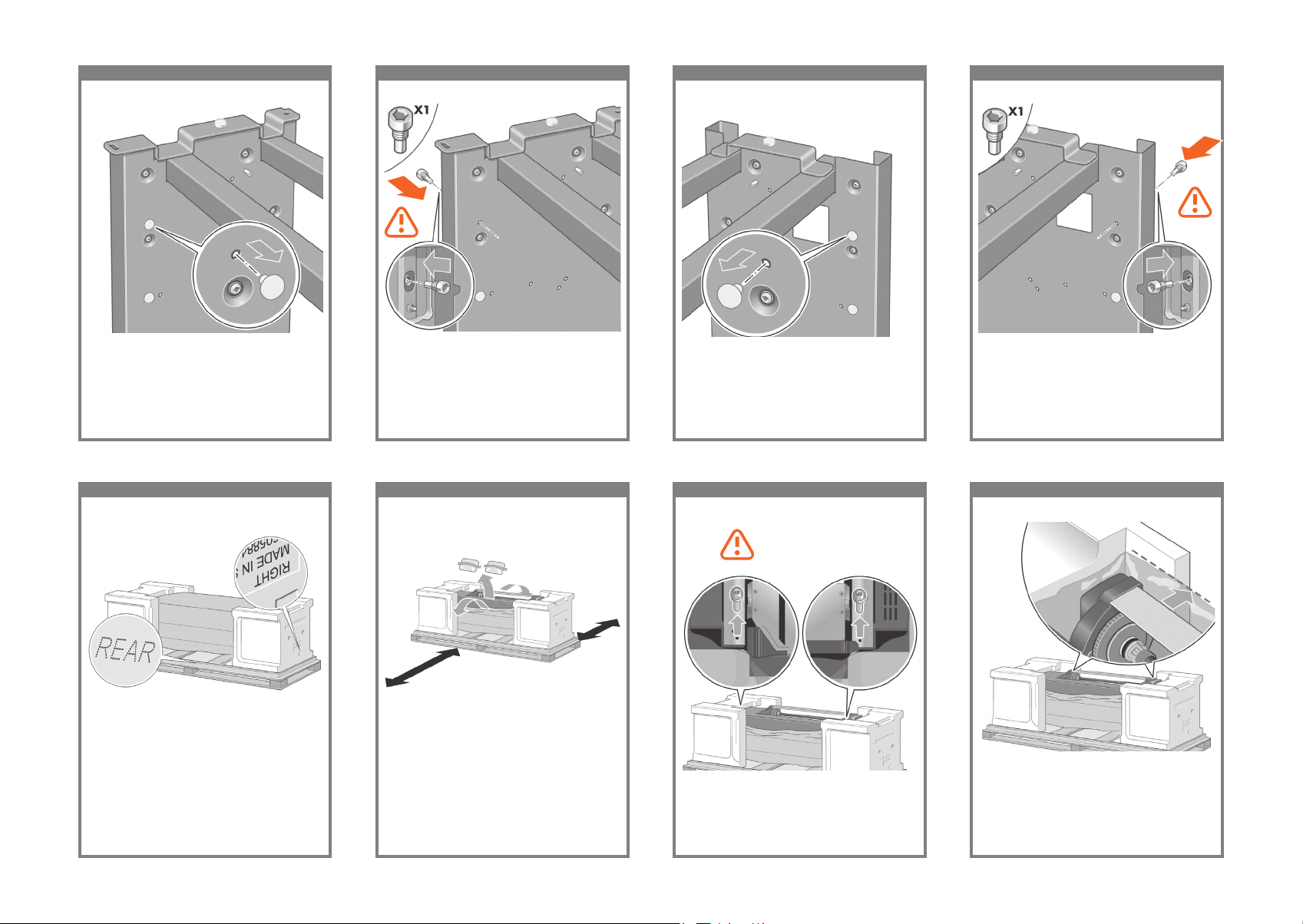
37 38 39 40
Locate the pin into the interior of the right leg.Remove the top yellow plug on the left leg. Locate the pin into the interior of the left leg. Remove the top yellow plug on the right leg.
41 42 43 44
Slide Drawer 1 out until it touches the foam
packaging.
You now need to identify the left and right of the
printer. This information is shown on the foam
end packs. Also identify the rear of the printer.
Pull open the protective plastic from the base of
the printer. Please ensure that there is a threemeter space clear of obstructions to the rear
of the printer and one meter at the front of the
printer.
Remove the two desiccant bags from the printer.
Using the screwdriver supplied, remove the two
screws that hold Drawer 1 in place. Note: the
screws are only for transit, they are not to be
replaced.
Do not replace these
screws after removal!
Page 7
45 46 47 48
Slide Drawer 1 forwards to gain better access
for the front screw. Fix the left side of the stand
to the printer using two screws. Make sure that
the screws are fully tightened.
Advance warning: in the next step, make sure
you position the stand pins in the holes in the
center of the printer body brackets.
Lift the stand assembly onto the printer body.
The anti-slip material should face to the rear of
the printer.
Fix the right side of the stand to the printer using
one screw. Make sure that the screw is fully
tightened.
Left Leg
Right Leg
x2
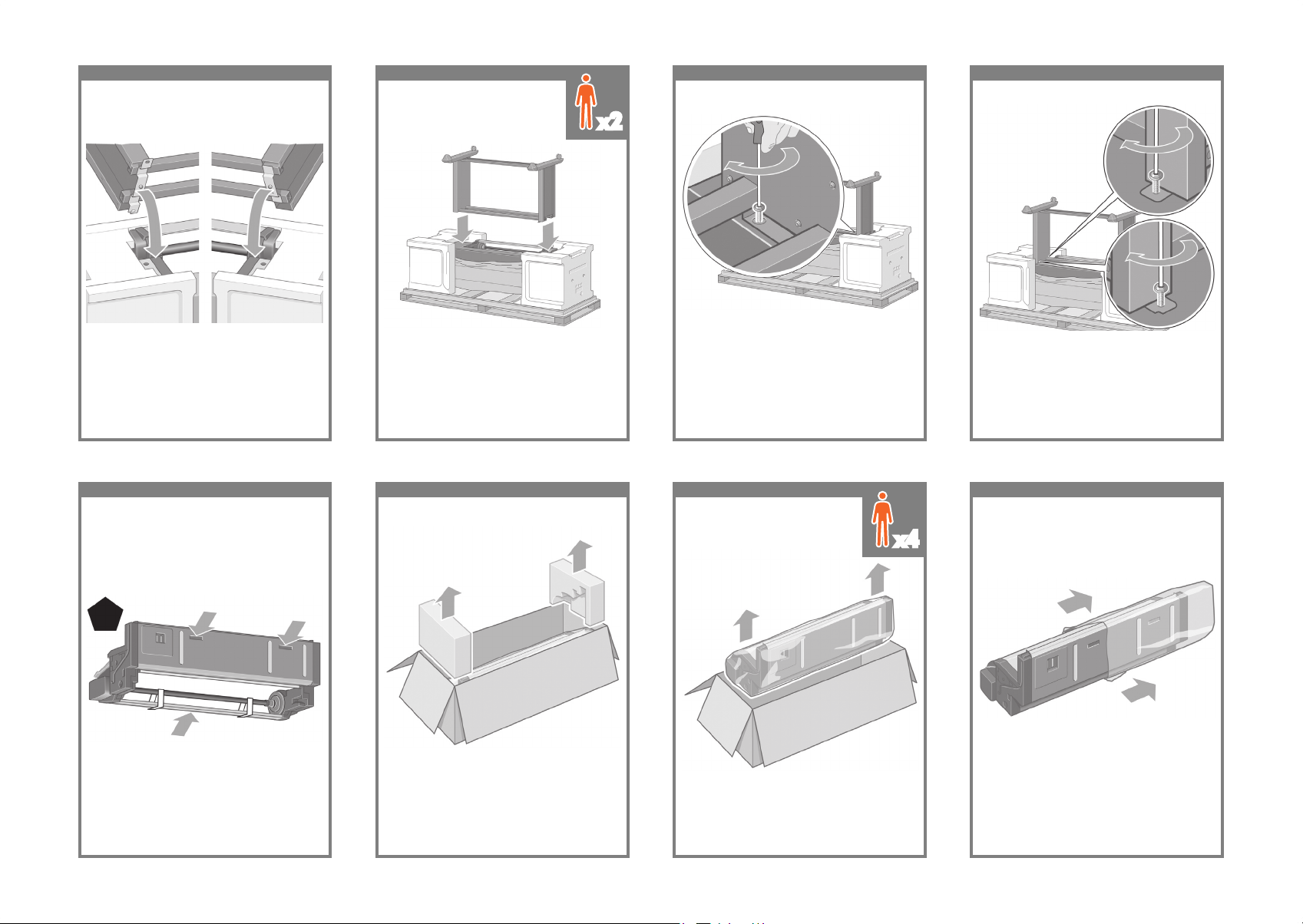
49 50 51 52
Remove the roll module from the plastic bag.Before unpacking the roll module, note that you
should only handle this piece of equipment using
the points indicated by the arrows shown
above.
Open the box containing the roll module, then
remove the two foam supports.
Remove the roll module from the packaging box.
IMPORTANT INFORMATION
x4
Page 8

53 54 55 56
Before the roll module is moved into its nal po-
sition, please note that it should sit on the pins
that were located on the stand legs earlier.
Remove the remaining two yellow plugs from the
left and right legs. It is important to remember
the positions of these holes.
Turn the roll module over into an inverted position as shown above. Then carry it to the front of
the inverted printer.
Rest the roll module next to the rst printer
crossbar.
x4x4
Rear of printer
57 58 59 60
Fix the roll module to the left leg of the stand
using two collar-headed screws.
Three people are needed, two at the front and
one at the rear of the printer. The two at the front
should lift the roll module and then, with the help
of the third person at the rear, lower it vertically
onto the pins located earlier on the stand.
Look at the front of the roll module and check
that it comes close to the legs of the stand
Fix the roll module to the right leg of the stand
using two additional screws.
x3
x2
x1
Page 9

61 62 63 64
Using four people, rotate the printer on to the
spare and consumables boxes.
Fix the roll module to the right leg of the stand. Fix the roll module to the left leg of the stand. Place the spare and consumables boxes against
the rear of the printer box. The arrows on the
boxes must point towards the printer box. Check
that the anti-slip material is still xed to the two
rear wheels.
x4
65 66 67 68
Rotate the printer into an upright position. The
anti-slip material should stop the printer from
sliding forwards.
Rotate the printer until its rear rests on the spare
and consumables boxes and the wheels with the
anti-slip material touch the oor.
Remove the pallet before trying to lift the printer
into an upright position.
Using four people and the hand holds on the
rear of the printer body, carefully lift the printer
into an upright position.
x4
Page 10

69 70 71 72
Remove the anti-slip material from the two rear
wheels on the stand assembly.
Remove the two foam end packs and the plastic
covering the printer.
Position the left leg cover on the front of the left
leg (1), then clip the rear edge (2) into place.
Position the right leg cover on the front of the
right leg (1), then clip the rear edge (2) into
place.
73 74 75 76
Open the printhead cleaner door (1) and
remove the carriage packing material (2). Then
close the cleaner door.
Remove the packing tapes 1 to 10. Open the printer window. Then remove the
two window inserts and the ink tube packing
material.
Remove the protective covering from the printer
window and the front panel screen.
Page 11

77 78 79 80
A Gigabit ethernet socket is provided for con-
nection to a network.
Two FireWire ® sockets are provided for direct
connection to computers.
Remove the two yellow plastic screws from the
right and left side of the paper feed. Caution: Be
very careful when removing.
Remove the two yellow plastic screws from the
left and right side of Drawer 2. Caution: Be very
careful when removing.
Using the cable supplied, connect the roll module to the printer.
81 82 83 84
Wait until you see this message (~10 minutes).
Highlight your language using the Up and
Down keys. Press the Select (ü) key.
Plug the power cable into the rear of the printer,
then plug the other end into the AC power outlet.
Turn the power switch at the rear of the printer to
the on position.
If the power light on the front panel remains off,
press the Power key to switch on the printer.
Note: This printer is Energy Star compliant and
can be left switched on without wasting energy.
Leaving it on improves response time and overall
system reliability.
Page 12

85 86 87 88
Open the ink cartridge door.The front panel will now display how to install
the ink supplies.
Remove the printheads, printhead cleaners, and
ink cartridges from the consumables box.
Find the ink cartridge door, which is on the left
side of the printer.
89 90 91 92
Position the ink cartridge at the rear of the
drawer as indicated.
To release the ink cartridge drawer, gently pull
the blue handle down.
Slide the ink cartridge drawer out. Place the ink cartridge onto the ink cartridge
drawer. Note that there are marks on the drawer
showing the correct location.
Page 13

93 94 95 96
Wait (about a minute) until you see this front
panel message.
Push the ink cartridge drawer back into the
printer until it locks into position.
Following the same instructions, install the other
three ink cartridges.
Close the ink cartridge door.
97 98 99 100
Lift up the cover. This will give you access to the
setup printheads.
Open the printer window. Remove the packing tape that is holding down
the printhead carriage latch.
Pull up and release the latch on top of the
carriage assembly.
Page 14

101 102 103 104
Lift the setup printhead until it is released from
the carriage assembly. Then remove the other
setup printheads.
Before removing the setup printheads, look at the
window on top of each one and check that the
printhead contains ink.
To remove a setup printhead, lift up the blue
handle.
Using the blue handle, gently disengage the
setup printhead from the carriage.
105 106 107 108
Make sure the printheads are correctly seated.
When all the printheads are installed, the front
panel prompts, “Close printhead cover and
window”.
Remove the blue protective cap and the clear
protective tape from the printhead.
Lower all the printheads vertically into their
correct positions.
Seat the printheads slowly and carefully.
Page 15

109 11 0 111 112
Close the printer window.
If “Reseat” is displayed on the front panel, check
that the protective tape has been removed.
Then try reseating the printhead more rmly.
If the problem persists, refer to the Driver and
Documentation CD.
Close the carriage assembly cover. Make sure the latch engages correctly.
11 3 11 4 11 5 116
Open the printhead cleaner door.
Please wait while the printer checks the
printheads (~1 minute).
Wait until you see this front panel message. Press the printhead cleaner door, which is on the
right side of the printer.
Page 16

117 11 8 119 120
Close the printhead cleaner door.Push the printhead cleaner in and down until it
clicks into place.
Insert the other seven printhead cleaners into the
correct slots.
Insert the printhead cleaner into the slot of the
correct color.
121 122 12 3 124
The front panel displays the above. Highlight
‘Load roll 1’ and press the Select key.
To load the paper roll from Drawer 1 into the
printer. From the front panel, highlight the Paper
icon and press the Select key.
From the front panel, highlight ‘Paper load’ and
press the Select key.
Wait until you see this front panel message.
Press the Select key.
Page 17

125 12 6 127 12 8
Remove the blue-colored stop from the left end
of the spindle. Keep the spindle horizontal.
Remove spindle from Drawer 1. Shown above is one of the core adaptors
supplied. Use these when the roll core is of a
larger diameter.
Using two hands, pull out Drawer 1.
129 13 0 131 132
Push the blue left-hand stop onto the roll. Make
sure it is correctly seated.
Push the black right-hand stop onto the roll.
Make sure it is correctly seated.
Put the blue-colored stop onto the spindle.Slide a roll onto the spindle. Make sure the
paper is oriented exactly as shown.
Page 18

13 3 13 4 135 13 6
Feed the paper from roll 1 onto the drawer 1
platen. Align the paper parallel with the blue
lines on the right side of the platen. The paper
edge does not need to be aligned exactly with
a specic blue line, but between the two outer
lines.
With the blue stop on the left, lower the spindle
into Drawer 1.
Lift the blue lever on Drawer 1. This is located
on the righthand side of the printer and above
Drawer 1.
As shown above, hold the spindle assembly
using the blue and black stops.
137 13 8 13 9 14 0
Using the stops, carefully wind the excess
paper back on to the spindle.
Lower the blue lever for Drawer 1. Push in Drawer 1.Feed the paper for a few centimeters more after
the printer beeps, then turn the roller backwards
to tension the paper correctly.
Page 19

141 14 2 14 3 144
From the front panel, highlight ‘Paper load’ and
press the Select key.
Select the roll length if known. To load the roll paper from Drawer 2: from the
front panel, highlight the Paper icon and press
the Select key.
The front panel displays the above. Highlight
the paper type you have loaded and press the
Select key.
14 5 14 6 147 14 8
Load the spindle using the same procedure as
described by points 127 to 133.
Using two hands, pull out Drawer 2. Remove the spindle from Drawer 2.The front panel displays the above. Highlight
‘Load roll 2’ and press the Select key.
Page 20

14 9 15 0 151 15 2
Feed the paper for a few centimeters more
after the printer beeps, then turn the roller
backwards to tension the paper correctly.
Lift the blue lever on Drawer 2. This is located
on the right-hand side of the printer and under
Drawer 1.
Feed the paper from roll 2 onto the drawer 2
platen. Align the paper parallel with the blue
lines on the right side of the platen. The paper
edge does not need to be aligned exactly with
a specic blue line, but between the two outer
lines.
With the blue stop on the left, lower the spindle
into Drawer 2.
153 15 4 15 5 15 6
The front panel displays the above. Highlight
the paper type you have loaded and press the
Select key.
Using two hands, push in Drawer 2. Using the stops, carefully wind the excess paper
back on to the spindle.
Lower the blue lever for Drawer 2.
Page 21

157 15 8 159 16 0
Your printer can be connected to a computer
directly or to one or more computers via a
network.
PC/Mac/Workstation
PC/Mac/WorkstationServerPrinter
Pass the LAN cable through the hook at the rear
of the printer.
The roll module provides an extra socket to connect an optional accessory.
Caution: do not attempt to use this socket for
any other purpose.
Select the roll length if known.
161 162 163 16 4
x2
Page 22

165 16 6 167
Legal notices
© Copyright 2009 Hewlett-Packard
Development Company, L.P.
The information contained herein is subject to change
without notice. The only warranties for HP products and services
are set forth in the express warranty statements accompanying
such products and services. Nothing herein should be construed
as constituting an additional warranty. HP shall not be liable for
technical or editorial errors or omissions contained herein.
Trademarks
Microsoft ®; and Windows ®; are U.S. registered
trademarks of Microsoft Corporation.
FireWire is a trademark of Apple Computer, Inc.,
registered in the U.S. and other countries.
Locate the bin against the printer.
Now you have completed the assembly of your
printer. The following page describes how to
congure your computer for successful printing.
Note for MAC & Windows USB connection:
Do not connect the computer to the printer yet. You must rst install the printer driver software on the computer.
Insert the HP start up Kit CD/DVD into your computer.
For Windows:
* If the CD/DVD does not start automatically, run autorun.exe program on the root folder on the CD/DVD.
* To install a Network Printer click on Express Network Install otherwise click on Custom Install and follow the instructions on your screen.
For Mac:
* If the CD/DVD does not start automatically, open the CD/DVD icon on your desktop.
* Open the Mac OS X HP Designjet Installer icon and follow the instructions on your screen.
NOTE: You can download the latest software from:
http://www.hp.com/go/4520/drivers
or
http://www.hp.com/go/4520ps/drivers
 Loading...