

Page 1

Page 2

For HP Internal Use Only
©Copyright Hewlett-Packard
Company 2004
This document contains
proprietary information that is
protected by copyright. All
rights are reserved. No part of
this document may be
photocopied, reproduced, or
translated to another language
without the prior written
consent of Hewlett-Packard
Company.
First Edition, May 2003
Second Edition, February 2004
Warranty
The information contained in
this document is subject to
change without notice.
Hewlett-Packard makes
no warranty of any kind
with regard to this
material, including, but
not limited to, the implied
warranties of
merchantability and
fitness for a particular
purpose.
Hewlett-Packard shall not be
liable for errors contained
herein or for incidental or
consequential damages in
connection with the furnishing,
performance, or use of this
material.
WARN ING
The procedures described in
this manual are to be
performed by HP-qualified
service personnel only.
Electrical Shock Hazard
Serious shock hazard leading
to death or injury may result if
you do not take the following
precautions:
- Ensure that the ac power
outlet (mains) has a protective
earth (ground) terminal.
- Disconnect the product from
the power source prior to
performing any maintenance.
- Prevent water or any other
liquids from running onto
electrical components or
circuits, or through openings in
the enclosure.
Electrostatic Discharge
Refer to the beginning of
Chapter 4 of this manual, for
precautions you should take to
prevent damage to the Printer
circuits from electrostatic
discharge.
WARN ING
The Warning symbol calls
attention to a procedure,
practice, or the like, which, if
not correctly performed or
adhered to, could result in
personal injury. Do not
proceed beyond a Warning
symbol until the indicated
conditions are fully understood
and met.
CAUTION
The Caution symbol calls
attention to an operating
procedure, practice, or the like,
which, if not correctly
performed or adhered to, could
result in damage to or
destruction of part or all of the
product. Do not proceed
beyond a Caution symbol until
the indicated conditions are
fully understood and met.
Content Management Department,
Barcelona Division,
Hewlett-Packard Espanola, S.A.
Avda. Graells, 501
08190 Sant Cugat del Valles
Spain
Safety Symbols
General definitions of safety
symbols are given immediately
after the table of contents.
Page 3

Page 4

Using this Manual
Purpose
This Service Manual contains information necessary to troubleshoot and
service:
hp designjet copier cc800ps - Model Q1261A
hp designjet 815mfp - Model Q1279A
hp designjet scanner 4200 - Model Q1280A
For information about using this product, refer to the corresponding User
and Quick Reference Guides.
This Service Manual is about the Scanner and the integration with the printer
as a copier. In order to troubleshoot the printer, refer to the corresponding
Service Manual for the printer.
Readership
The procedures described in this Service Manual are to be performed by HP
Certified service personnel only.
Part Numbers
Part Numbers for service parts are located in Chapter 3.
Conventions
A small arrow ⇒ is used to indicate other parts of the Service Manual where
you can find information related to the topic you are consulting.
2
hp designjet scanner series service manual
Page 5

Table of Contents 1
Troubleshooting 1-1
System Error Codes 2-1
Parts and Diagrams 3-1
Removal and Installation 4-1
Adjustments 5-1
Table of Contents
hp designjet scanner series service manual
3
Page 6

Table of Contents
4
hp designjet scanner series service manual
Page 7

Troubleshooting 1
Is the Problem with the Printer or Scanner 1-2
Image Quality Problems 1-2
Output Problems 1-2
Troubleshooting System Error Codes 1-3
Using the SCANtest 6 Diagnostic Software 1-3
Cleaning the Scanning Area 1-8
Vertical Line(s) Problem 1-11
Vertical Line(s) Problem 1-11
Firmware Related Errors 1-11
Stepper Motor Does Not Work 1-11
Lamp Does Not Work 1-11
Problem with the Rollers 1-11
Media Loading Problems 1-11
Fan Problems 1-11
Horizontal Banding Problem 1-12
Dust on Glass Plate 1-12
Problems with the Software 1-12
Troubleshooting Tips 1-12
Troubleshooting Guide - Update 1-13
Preventive Maintenance Kit for HP DesignJet Scanners 1-25
Panel PC (Touch Screen) Problems 1-26
1
HP Designjet 4500 Scanner Service Manual
1-1
Page 8

Troubleshooting
Guide to Troubleshooting the HP Designjet 4500 Scanner
Is the Problem with the Printer or Scanner
If you encounter the following symptoms, the problem could be related to the
scanner:
System Error on the Touch Screen.
LED’s flashing on the Scanner Operator Panel.
WIDEsystem error message.
1 vertical white, black or color line.
If you encounter the following symptoms, then perform an Image Preview
and send a Test Print:
Image Quality Problems.
No Output.
Output is not as expected.
If the Image preview fails, this points to a problem with the Scanner. If the
Test Print fails, this points to a problem with the Printer.
Image Quality Problems
If you have Image Quality problems in any prints, try the following:
1 Print out a file already stored or print out a demo file.
2 Once the print is finished, insert it into the Scanner.
3 Once scanned, print out the scanned image.
If the original print is the same as the copied print, then the problem is
associated with the Printer.
If the original print is NOT the same as the copied print, then the problem
is associated with the Scanner.
Output Problems
If the output is not as you expected it to be, try the following:
Check all the settings in the Software: Color Settings and Margins.
Check media settings: Media profile (in software) and media loaded in
the printer (front panel selection) should be the same.
Perform Color Calibration (both Scanner and printer).
Check the Preview Image.
If there is no output at all, then try the following:
1-2
Check the connection between the Printer and the scanner.
Check the selected settings: List, Collate, Scan to file...
HP Designjet 4500 Scanner Service Manual
Page 9

Troubleshooting
Troubleshooting System Error Codes
Chapter 2 - System Error Codes contains a list of system error codes and
their respective descriptions and recommended corrective actions. Only try
one recommended action at a time and check if the error code has
disappeared.
Using the SCANtest 6 Diagnostic Software
Here we briefly describe the various tests found in the SCANtest 6
Diagnostic Software, for more detail of some of the Adjustments shown
below refer to Chapter 5 - Adjustments
The purpose of the SCANtest 6 diagnostic software is to support the
troubleshooting and adjustment of the Scanner.
When the SCANtest 6 diagnostic software has been started, the Scanner is
switched ON in Test Mode, and the Diagnostic LED on the Operator Panel is
turned ON.
Scanner Test Program Menu
Test 1: Scanner Information
Test 2: LED Test
Test 3: Key Test
Test 4: Original-Sensor Test
Test 5: Lamp Test
Test 6: Motor Test
Test 7: Complete Hardware Test
Test 9: Camera Adjustment
Test 11: Stitching and Vertical Alignment
Test 12: Adjust Y-Axis Scaling
Test 13: Switch Scanner to Test Mode
Test 20: Noise Test
Test 21: Scan Dump
Test 27: Camera Adjustment Wizard
Test 28: Original Guide Sensor Test
Test 30: Calibrate ATAC
Test 31: Driver Board Communication Test
If SCANtest 6 is started when the scanner is in Error Mode, the Error Code
Number and a short description of the error will be displayed on the screen.
Test 1: Scanner Information
This test displays general information regarding the scanner. When
executed, the test displays the following:
Scanner Model:
Firmware Release:
Firmware Release Date:
Firmware Build:
FPGA Revision:
HP Designjet 4500 Scanner Service Manual
1-3
Page 10
Troubleshooting
FPGA Release Date:
Boot Code Revision:
Boot Code Release Date:
Scanner ID Switch:
SCSI ID:
Test 2: LED Test
This test checks the functionality of the LED Indicators on the Operator Panel.
When the test is executed, all the LEDs are sequentially switched ON/OFF
until Test 2 is terminated. If any of the LEDs fail, you will NOT get an error
message, instead the LED will NOT switch ON or OFF. If the LED test fails,
replace the Right Cover (which contains the Operator Panel).
Test 3: Key Test
This test checks the functionality of the Keys on the Operator Panel. When
the test is executed, each key on the Operator Panel will turn an LED ON
when pressed.
Key
Forward and Reverse Ready (Green)
Power Wait (Yellow)
The only way to know if the test fails is by inspection, there is no error
message that is displayed.
If the Key test fails, replace the Right Cover (which contains the Operator
Panel).
Test 4 : Original-Sensor Test
This test checks the functionality of the Media Sensors and the Media
Thickness Detector.
When the test is executed, the following LEDs turn ON when one of the
Media Sensors is activated, or when one or both Adjustment Sliders for
Media Thickness are pulled out from Normal position:
Actuator
Media Entry Sensor Ready (Green)
Media Exit Sensor Ready (Green)
Adjustment Slider for Media Thickness Wait (Yellow)
LED
LED
1-4
To test the Adjustment Slider for Media Thickness (located on the Guide
Plate), press the slider towards the center and the Wait LED switches On.
To test the Media Sensors, load a Sheet of media (A4) and the Ready LED
switches ON and when you remove it the Ready LED switches OFF.
If the test fails (if any of the LEDs fail to switch ON), then the problem will be
HP Designjet 4500 Scanner Service Manual
Page 11

Troubleshooting
related to corresponding Sensor.
Test 5: Lamp Test
This test checks the functionality of the Lamp and associated electronics.
When the test is executed, a message on the screen will indicate whether the
Lamp is turned ON or OFF (Lamp power is turned ON/OFF) and whether
the Light is ON/OFF (Light is detected or not). The Lamp is delayed for
approximately 2 seconds when switched ON.
Test 6: Motor Test
This test checks the functionality of the Stepper Motor and any associated
electronics.
When the test is executed, a menu appears that allows you to select the
motor speed and the motor direction.
If the Stepper Motor or the Driver Board fails to run when the test is
executed, then the Stepper Motor should be replaced.
Test 7: Complete Hardware Test
This test checks the various functions of the Driver and Camera Boards.
Test 9: Camera Adjustment
We recommend that you use Test 27 to adjust the camera
because there is a wizard which guides you through the
complete process.
This test contains a Software Oscilloscope that allows you to check and
adjust the CCD-Cameras. The following functions can be selected from the
Test Program Menu.
Uncorrected or Corrected Light Profile.
Red, Green, or Blue Color Channel.
Special Detail Views for Light Profile, Scan Width, and Vertical
Positioning.
Forward / Reverse controls for the Camera Motor.
Save screen images.
Print screen images.
The content of the Detail Views is marked on the upper overview window by
red vertical lines. The continuous lines refer to the left Detail View and the
dashed lines to the right Detail View.
To perform the Camera Adjustment, refer to Chapter 5 - Adjustments of this
Service Manual.
HP Designjet 4500 Scanner Service Manual
1-5
Page 12

Troubleshooting
Test 11: Stitching and Vertical Alignment
This test is also included in the Scanner Maintenance Software.
This test performs Automatic Vertical Alignment and Horizontal Stitching.
Once the test has been started:
Insert SM Calibration Sheet.
Select Vertical Alignment to align the cameras.
Select Horizontal Stitching to stitch the cameras.
The screen image can be saved or printed.
This test allows manual setting of the Stitch Values. The Stitch Values are
stored in the Flash Memory on the Driver Board.
The Vertical Alignment may be adjusted manually by controlling the Camera
Motor from the control field ‘<<dddd>>’. The two buttons marked ‘<<’
respectively ‘>>’ are used to start the motor and to determine the direction of
rotation. When started, the motor runs for dddd mili-seconds as entered into
the control field.
Test 12: Adjustment of Y-Axis Scaling
This test allows you to adjust the Y-Axis Scaling.
The scaling (dpi) in the mechanical scan direction (Y-Axis) depends on the
speed of the stepper motor relative to the scanline Exposure Time. The
default motor speed can be changed ± 1%, either from Test 12 or by using
the ‘Scanner Setup/Correction factor …’ option of SW copying. The
correction factor is stored in the Flash Memory on the Driver Board.
Test 13: Switch Scanner to Test Mode
This test allows you to switch the scanner back to Test Mode. Useful if the
scanner gets out of Test Mode, e.g. if it has to be turned OFF/ON during
troubleshooting.
Test 20: Noise Test
The purpose of this test is to detect and locate the possible cause (dust, dirt,
scratches,..) of vertical lines running from top to bottom of the scanned
image.
When the test is executed, it scans the White Calibration Area of the SM
Calibration Sheet and displays, for each color channel, the graytone values
of each separate pixel averaged over the scanned band.
The displayed image of the SM Calibration Sheet will be superimposed by
low level noise caused by the CCD chip, and larger spikes most likely caused
by dust, dirt, scratches, or similar defects on the Glass Plate. In rare cases,
larger spikes may be caused by dust, dirt, or pixel faults on the CCD chip.
The positions of larger spikes are shown by the numbers (cm or inch units)
opposite to the spikes. The numbers refer to the Sideload-ruler on the
scanner. Larger spikes going downwards are often caused by dust, dirt,
scratches, or similar defects on the Glass Plate and may be removed by
cleaning the Glass Plate. Downward spikes often show up as darker vertical
lines in the scanned image.
1-6
HP Designjet 4500 Scanner Service Manual
Page 13

Troubleshooting
Larger spikes going upwards are often caused by dust or dirt present on the
Glass Plate during the last calibration with Scanner Maintenance. These
defects are memorized by the Light Profiles stored in the Flash Memory and
can only be removed by cleaning of the Glass Plate followed by running
Scanner Maintenance again. Upward spikes show up as very bright vertical
lines in the scanned image.
White vertical lines in the scanned image may be found even if Noise Test
shows a perfectly ‘clean’ scanner. In this case, the cause may be white dust
or particles on the backside of the Glass Plate having the same color as the
white background. In this case, the Light Profiles of SCANtest 6, Test 9 may
show upwards going spikes when a dark original is placed in the scan-area.
Test 21: SCANdump
The purpose of this test is to create a file, SCANdump.con, which contains
Light Profiles and other scanner data for diagnostics purposes.
When the test is executed, the file SCANdump.con will be placed in the
directory c:\Temp\. The files contained in SCANdump.con may be
unpacked by SCANview 6 by double clicking on SCANdump.con. The
unpacked Light Profiles may be viewed by SCANview 6. If other files are
included, use an appropriate reader or viewer.
The files are also placed as a button on the active desktop and is called
SCANdump. The files can be stored on a disk and can be sent by e-mail.
Test 27: Camera Adjustment Wizard
This allows you to adjust the Camera using a wizard that guides you through
the complete process. Use this test instead of Test 9 (whenever possible). See
5-7, Adjusting the Camera Using the Camera Wizard
Test 28: Original Guide Sensor Test
This is to test the Original Guide Sensors which are located under the Top
Profile. See 5-27, Original Guide Sensor Test
Test 30: Calibrate ATAC (Automatic Thickness Adjustment
Control)
This test sets the current level at which the ATAC will stop if something is
preventing it from moving down. See 5-31, Calibrate ATAC (Automatic
Thickness Adjustment Control)
Test 31: Driver Board Communication Test
This test checks the communication between the Scanner and the Driver
Board. See 5-31, Driver Board Communication Test
HP Designjet 4500 Scanner Service Manual
1-7
Page 14

Troubleshooting
Cleaning the Scanning Area
When cleaning any part of the scanning area DO NOT use abrasives,
acetone, benzene or fluids that contain these chemicals. Do not spray liquids
directly onto the scanner glass plate or anywhere else in the scanner.
1 Turn the scanner power off.
2 Disconnect the scanner power cable.
3 Open the Top Profile by pushing down on the left and right locking levers
and flip it upwards to expose the scan area.
4 Gently wipe the Glass Plate. Clean the glass with a lint-free cloth and a mild,
streak-free, glass cleaner.
5 Dry the glass completely using a separate clean, dry lint-free cloth like the
one provided with the maintenance kit.
1-8
HP Designjet 4500 Scanner Service Manual
Page 15

Troubleshooting
6 Clean the white background assembly. Wipe the white metal area with a
lint-free cloth and a mild, streak-free, glass cleaner.
7 Clean the platen rollers. Wipe the rollers with a lint-free cloth and a mild,
streak-free, glass cleaner.
8 Dry the platen and rollers completely using a separate clean, dry lint-free
cloth.
HP Designjet 4500 Scanner Service Manual
1-9
Page 16

Troubleshooting
9 Close the Top Profile.
10 Use the dust sheet to protect the Scanner when not in use.
1-10
HP Designjet 4500 Scanner Service Manual
Page 17

Troubleshooting
Vertical Line(s) Problem
A dust particle on the glass plate can produce a vertical white or black line. To
make sure that the line is caused by dust, preview the image and inspect the
preview using the viewing section buttons. To solve the problem, try the following:
Perform Scanner Maintenance: Cleaning and Camera Alignment. Using
Test 20 from SCANtest 6 may help to identify dusty/dirty areas.
Firmware Related Errors
If you have any firmware related errors, try the following:
Upgrade the Firmware.
Stepper Motor Does Not Work
If the Stepper Motor does not work, try the following:
Use Test 6: Motor Test to check the functionality of the Stepper Motor.
Replace the Driver Board.
Replace the Stepper Motor.
Lamp Does Not Work
If the Lamp does not work, check that the Driver Board is connected to the
Power Supply Unit. Also check the Lamp Sensor and the Driver Board since
these two parts work together with the Lamp.
Problem with the Rollers
If there is a skewing problem and replacing the Guide Plate does not solve
the problem, then the problem maybe with the Rollers. In this case, replace
the Rollers.
Media Loading Problems
If it not possible to load media or if there are media loading problems, try
the following:
Check the Original Sensor (green LED when loading media) or use Test
4: Original-Sensor Test to check the functionality of the sensor.
Use Test 6: Motor Test to check the functionality of the Stepper Motor.
Fan Problems
If the Fan is not working then try the following:
Check the Fan to make sure that it is connected correctly.
If the Fan is connected correctly, then replace the Driver Board or the
Fan.
If the Fan and Driver Board are working correctly, the problem could be
related to the NTC Sensor.
HP Designjet 4500 Scanner Service Manual
1-11
Page 18

Troubleshooting
Horizontal Banding Problem
If the tracking mechanism can not adjust the light, horizontal banding will
appear on the images. To solve the problem, try the following:
Test the Printer to make sure that it is printing correctly.
Adjust the Driver Board (it can only be adjusted if the Lamp is NEW):
Make sure both LEDs are ON. If both LEDs are not ON, then check that
the Lamp is ON. If the Lamp is OFF, then replace the Lamp or the Driver
Board. If the Lamp is ON, then replace the Driver Board or Lamp Sensor.
Dust on Glass Plate
If there is dust on the glass plate, try the following:
Run Test 20: Noise Test to find the dust on the glass plate.
Perform Scanner Maintenance: Cleaning and Camera Alignment.
Problems with the Software
If there are problems with the Software, try the following:
Use the Recovery CD.
After using the Recovery CD, setup the system on the network again (if
necessary).
If after using the Recovery CD the problem continues, then try running the
Recovery CD again but this time use the option C and D drive.
Troubleshooting Tips
1 First record whether the problem is with the printer, scanner or the Touch
Screen.
2 Make sure that the scanning area is completely clean.
3 Test 20: Noise Test can help you to find where the scanning area is dirty.
4 The SCAN dump files can help understand the light profile of the affected
scanner.
5 Remember, in order to cancel when copying, press the Cancel button on the
Touch Screen and the Cancel button on the printer.
1-12
HP Designjet 4500 Scanner Service Manual
Page 19
Troubleshooting
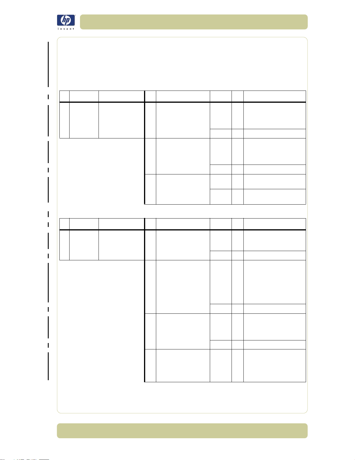
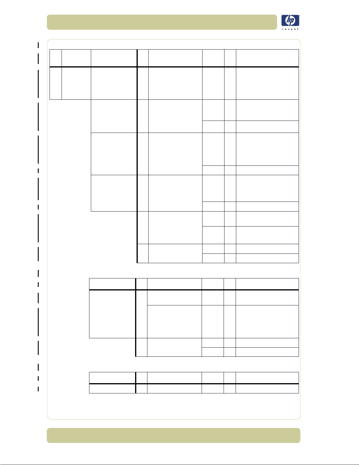
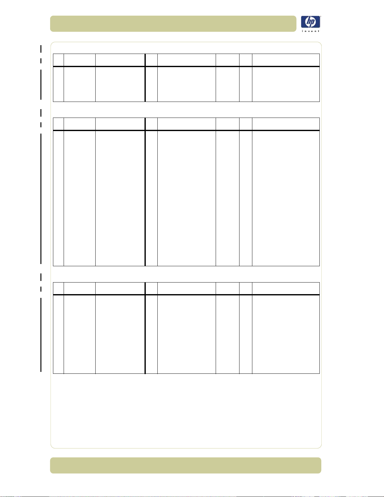
Troubleshooting Guide - Update
The following guide will help you find a solution to some typical problems
that some customers may experience. The problems (P#) that can be done
by the customer are marked C, and the problems that need an intervention
by a Support Technician are marked T.
P# Category Problem Q# Question Yes/No C/T Solution
1Copy
problem
P# Category Problem Q# Question Yes/No C/T Solution
2Copy
problem
The colors on one
side of the copy does
not correspond to the
colors on the other
side of the copy
I get thin lines of
wrong colors in my
copy
1 Have you cleaned and
calibrated your scanner
recently?
2
Have you upgraded the
scanner firmware to the
latest version?
3
Have you upgraded the
system software to the
latest version?
1 Are the lines vertical and
also present in your
preview?
2
Are the lines horizontal
and equally spaced?
3
Are the lines horizontal,
but irregular (maybe only
1 line)?
4
Do you have a great
number of regular spaced
lines very close to each
other and restricted to one
side (1 camera) only?
No C Camera differences - The
scanner needs to be cleaned
and calibrated (refer to P22
Yes Refe r to Q2
No C Upgrade scanner firmware to
version 2.5, use the Update
Yes Refe r to Q3
No C Upgrade system software
Yes T Ca meras need adju sting or
Yes C The scanner needs to be
No Refer to Q2
Yes C
No Refer to Q3
Yes C The lines could be caused by
No Refer to Q4
Yes T You h ave a camera error.
the Camera Board replacing
cleaned and calibrated (refer
Check printheads by starting
function in the Designjet Scan
also get an idea whether the
scanner firmware and system
and P23)
latest version (from system
System CD)
(use Update System CD)
to P22 and P23)
printhead test on Printer. By
using the built-in test print
Copy application, you can
Printer is performing OK
a data error. Upgrade
software
Replace Camera Board
HP Designjet 4500 Scanner Service Manual
1-13
Page 20

Troubleshooting
P# Category Problem Q# Question Yes/No C/T Solution
3Copy
problem
P# Category Problem Q# Question Yes/No C/T Solution
4Copy
problem
I get thick lines of
slightly wrong colors
in my copy
Some colors are not
the same when I
compare the master
print with the copy
1 Are the lines vertical and
also present in your
preview?
2
Are the lines horizontal
and equally spaced?
1 Is the scanner clean and
calibrated?
2
Do you use the correct
media profile for the
actual media?
3
Is the media profile valid?
4
Is the option 'Ink Printer
Original' set in
accordance with your
original?
5 Is the media you are
printing on the same type
as the original?
Yes C The scanner needs to be
No Refer to Q2
Yes C
No Refer to P2
No C Refer to P1. Clean and
Yes Refer to Q2
No C If you are using e.g. Glossy
Yes Refer to Q3
No C Create a new media profile
Yes Refer to Q4
No C If original was printed using
Yes Refer to Q5
No C e.g. Use Glossy Media to
Yes C Create a new media profile
cleaned and calibrated (refer
to P22 and P23)
Check printheads by starting
printhead test on Printer. By
using the built-in test print
function in the Designjet Scan
Copy application, you can
also get an idea whether the
Printer is performing OK
calibrate the scanner (refer to
P22 and P23)
Media for this copy, the
media profile selected should
also be for Glossy Media.
Best results are obtained by
making your own media
profiles
(refer to P24)
an Inkjet Printer, set this
option (refer to P25)
reproduce a Glossy original
(refer to P24)
1-14
HP Designjet 4500 Scanner Service Manual
Page 21

Troubleshooting
P# Category Problem Q# Question Yes/No C/T Solution
5Copy
problem
Only a part of the
master print is being
copied
1 Are you scanning a thick
original?
2
Have you selected 'Auto
3
size'?
Is the length too short
and the width OK?
Yes C Uncheck extended media
handling box in scanner
settings (using extended
media will load the original
between both entry and exit
rollers before scanning - this
means that you will not have
the start of the thick original
scanned. Also the scan speed
will be slower, and no "back -
ups"/reversing is allowed
while scanning)
No Refer to Q2
Yes C The scanner needs to be
cleaned (refer to P22)
No Refer to Q3
Yes C The problem may be with the
Printer (not able to print close
to the edges) or Panel PC
(Hard Disk is full). To check
Hard Disk space, use
windows explorer and look at
partition D:
No C Check that the margins that
are set are not too big. Also
check Scanner Media Offsets
P# Category Problem Q# Question Yes/No C/T Solution
6 System Error What should I do
when the program
hangs?
1Are you running a copy
job?
2
Are you trying to run
more than one scanner
application at the same
time?
Yes C Making a copy takes a lot of
resources according to the
settings. Wait till the copy is
done before performing
another action
No Refer to Q2
Yes C You c an on ly run o ne
application at the same time.
Please close either the
Scanner Maintenance
application or the copier
software
No C Restart the system. If the
problem keeps coming back,
please run the System
Recovery (refer to P12)
HP Designjet 4500 Scanner Service Manual
1-15
Page 22

Troubleshooting
P# Category Problem Q# Question Yes/No C/T Solution
7 File problem When I scan to file,
the file is very big
1Are you scanning in
2
Are you scanning in gray
color?
tones?
Yes C Scanning large drawings will
generate very big files. An
A0 color drawing scanned at
300 dpi will generate a file
size of approx. 3 Gigabytes
when scanned in an
uncompressed format. In
order to reduce file size,
select Tiff - pack bits as
format. You can reduce size
even more by selecting JPEG
format, but this format will
reduce picture quality
No Refer to Q2
Yes C Scanning large drawings will
generate big files. An A0
gray tone drawing scanned
at 300 dpi will generate a
file size of approx. 300
Mbytes when scanned in an
uncompressed format. In
order to reduce file size,
select Tiff - pack bits as
format. You can reduce size
even more by selecting JPEG
format, but this format will
reduce picture quality
No In order to reduce file size on
scanned B/W drawings,
select Tiff group 4
compression
P# Category Problem Q# Question Yes/No C/T Solution
8 File problem When I scan to file
my application
cannot read the file
1-16
1Did you get an error
message when creating
the file?
HP Designjet 4500 Scanner Service Manual
Yes C Check that you have enough
disk space and scan to file
again, choosing Tiff
uncompressed as format
No C We only recommend to use
the built-in viewer for file
viewing. Large format
drawing files may not load
correctly in other viewers due
to file size. Try to scan a
smaller original (A4)
Page 23

Troubleshooting
P# Category Problem Q# Question Yes/No C/T Solution
9Copy
problem
P# Category Problem Q# Question Yes/No C/T Solution
10 Copy
Problem
Which setting will
give me the best
result when copying?
Nesting feature is not
working
-- -C
1 Is the correct printer
selected?
2
Is the Hard Disk close to
being full?
No C Select the correct Printer
Yes Refer to Q2
Yes C Free up some space, or try to
No C Make sure that Nesting is set:
See section about media
profile (P4). Use copy quality
best. Choose the correct Type
of original ("Map" for maps,
"Photo" for photos, etc).
Eventually go to Original
Setup to fine adjust colors
and sharpening. (See also
system help for more details -
button with "?" symbol)
run a nesting job with only 2
or 3 small pictures. If that
works refer to P27
Select: |Output|
Layout|Nesting|optimized|
P# Category Problem Q# Question Yes/No C/T Solution
11 Network
Problem
P# Category Problem Q# Question Yes/No C/T Solution
12 Recovery How and when is the
I cannot access the
system from the
network
Recovery CD used?
1 Is the PC connected to
the network?
2
Is the web server-FTP
server enabled in the
system?
-- -C
Yes C D o ba sic network
troubleshooting
No C Connect the PC to the
Network
Yes C Go into the ISS manager and
restart the server
No C Go into the ISS manager and
enable the web/FTP server
The recovery CD is used if the
system needs to be
reinstalled. Insert the CD in to
the PC and reboot the system
HP Designjet 4500 Scanner Service Manual
1-17
Page 24

Troubleshooting
P# Category Problem Q# Question Yes/No C/T Solution
13 Scanner
Calibration
Problem
Scanner
Maintenance did not
succeed
1 Did any error occur when
performing the Scanner
Maintenance?
2
Error: "Basic calibration
was performed. but failed
to stitch scanner" or
"Could not find horizontal
line" or "Could not read
bar lines" or "Could not
recognize the scanned IT8
3
4
5 Have you upgraded the
6 Have you upgraded the
picture"
Error: "Sheet not
recognized"
Error: "No movement in
camera position has been
detected during vertical
camera alignment"
scanner firmware to the
latest version?
system software to the
latest version?
Yes C Re fer to Q 2
No C Clean the scanner and then
run Scanner Maintenance
again (refer to P22 and P23).
If that does not help, refer to
Q5
Yes C Clean the scanner and then
run Scanner Maintenance
again (refer to P22 and P23).
If that does not help, refer to
Q5
No Refer to Q3
Yes C Reinsert calibration sheet
correctly and run Scanner
Maintenance again. If that
does not help, refer to Q5
No Refer to Q4
Yes T Please check camera. Run
Camera Adjustment Wizard
(CAW)
No Refer to Q5
No C Upgrade scanner firmware to
latest version (from system
version 2.5, use the Update
System CD). Clean the
scanner and then run
Scanner Maintenance again
(refer to P22 and P23)
Yes Refer to Q6
No C Upgrade system software (use
Update System CD). Clean
the scanner and then run
Scanner Maintenance again
(refer to P22 and P23)
Yes T Please check camera. Run
Camera Adjustment Wizard
(CAW)
P# Category Problem Q# Question Yes/No C/T Solution
14 Copy
problem
1-18
The Collate Copy
function does not
work
1 Is your Hard Disk close to
full?
HP Designjet 4500 Scanner Service Manual
Yes C Free up some space, or try to
No C
run a collate job with a
smaller picture. If that works,
refer to P27
Follow the step by step
instructions in the online
manual under "Collate Copy"
Page 25

Troubleshooting
P# Category Problem Q# Question Yes/No C/T Solution
15 Copy
problem
The lines are not
accurate
1 Are the lines wavy and
irregular?
2
Are the lines not sharp?
3
Are the lines broken and
the errors situated in a
vertical column between
2 columns?
Yes C/T C: The original could be
curled or crumpled. Try
Straightening it (in case of
very irregular waves there
could be a mechanical
problem with the scanner). T:
check motor and belt drive
tension according to TSM
No Refer to Q2
Yes C/ T C: Are you using the correct
copy method? Try
sharpening. If sharpness is
different between Cameras,
you may have a Focus
Problem. T: Check focus of
cameras with Focus
Adjustment Pattern
No Refer to Q3
Yes C You might have a visible
stitching error (refer to P26)
No C Check the dpi. In the case of
too low resolution, jagged
diagonal lines will appear
P# Category Problem Q# Question Yes/No C/T Solution
16 System error I cannot install my
P# Category Problem Q# Question Yes/No C/T Solution
17 Copy
Problem
application on the
system
One side of the
preview is black
-- -C
1 Have you upgraded the
scanner firmware to the
latest version?
2 Have you upgraded the
system software to the
latest version?
No C Upgrade scanner firmware to
Yes Refer to Q2
No C Upgrade system software (use
Yes T Most likely a Camera Error.
The copy system is only meant
to handle the factory installed
software and applications.
The system is unsupported if
you choose to install other
latest version (from system
version 2.5, use the Update
System CD)
Update System CD)
Run Camera Adjustment
Wizard. Replace the Camera
Board if necessary
software
HP Designjet 4500 Scanner Service Manual
1-19
Page 26

Troubleshooting
P# Category Problem Q# Question Yes/No C/T Solution
18 Updating How do I update the
P# Category Problem Q# Question Yes/No C/T Solution
19 Start-up
Problem
system?
The system does not
power up
-- -C
1 Is the system is dead, that
is, no LEDs on the
scanner are ON, PPC
screen is black, and no
fan-noise is heard?
2
Does PPC start with the
normal initial screen?
3
Does PPC start normally,
but the software does not
4
5 Is the Scanner dead, that
6 Does the scanner hang-
work?
Is the PPC dead, that is,
no fan noise, and no
screen image?
is, no fan noise and no
LEDs lit?
up with all LEDs ON?
Yes C 1 - Check that all power
No Refer to Q2
Yes C Re fer to Q 5
No Refer to Q3
Yes C Run Recover Disk
No Refer to Q4
Yes T Replace the PPC
No Refer to Q5
No Refer to Q6
Yes T Check, and if necessary
Yes T Try th e followi ng:
No Refer to P21
Insert the HP Update CD in to
the CD drive and press
"Upgrade system"
switches on the equipment
2 - Check if there is power at
the wall outlet
3 - Check power cables
between wall outlet and the
individual units.
1 - Power Supply Unit
2 - Driver Board
1 - Erase parameter block
2 - Update the firmware
3 - Replace the Main Board
are ON
replace:
1-20
HP Designjet 4500 Scanner Service Manual
Page 27

Troubleshooting
P# Category Problem Q# Question Yes/No C/T Solution
20 Mechanical
Problem
P# Category Problem Q# Question Yes/No C/T Solution
21 Error Code I get an Error Code,
I cannot load the
original
what do I do?
1 Please try to load a new
piece of A4 paper at the
center of the scanner.
Does this paper load?
2
Can paper be loaded by
pressing the "Forward"
key?
3
Does the Ready LED turn
ON when activating
Original Sensor (insert
paper)?
-- --
1 Have you upgraded the
scanner firmware to the
latest version?
2 Have you upgraded the
system software to the
latest version?
Yes C You have a problem with
your original. Please check
that paper edges are not bent
or curled in any way
No Refer to Q2
Yes C Refer to Q3
No T Try replacing the following:
1 - Driver Board
2 - Power Supply Unit
3 - Feed Motor
4 - Main Board
No T Check, and if necessary
Re-power the system, and check
if the error code reappears. If it
No C Upgrade scanner firmware to
latest version (from system
version 2.5, use the Update
Yes Refe r to Q2
No C
Upgrade system software (use
Update System CD). Check if
Error Codes reappears. If it
replace:
1 - Original Sensors
2 - Main Board
does, refer to Q1
System CD)
does, refer to P21a
HP Designjet 4500 Scanner Service Manual
1-21
Page 28
Troubleshooting
P# Category Problem Q# Question Yes/No C/
21a Error Code I still get an error
code, what do I do?
Error Code 30-xxx Have you cleaned the
Error Code 32-xxx Have you cleaned the
Error Code 40-xxx 1 Does the Lamp light up? No T Try replacing the following:
Does the Diagnostic LED
(and, in some cases also
other LEDs) blink?
white background and
glass plate, and
performed Scanner
Maintenance?
white background and
glass plate, and
performed Scanner
Maintenance?
2 Have you cleaned the
white background and
glass plate, and
performed Scanner
Maintenance?
3
Is it Error Code 40-136,
138 or 174-187?
Yes C
Yes T Check Camera Adjustment. If
No C Refer to P22 and P23
Yes T Try the following:
No C Refer to P22 and P23
Yes Refer to Q2
Yes Refer to Q3
No C Refer to P22 and P23
Yes T Replace Lamp
No T Replace Camera Boards
Solution
T
Lower Original Guide to
Normal position, start Preview
Scan to obtain an Error Code
or check if WIDEsystem gives
an Error Code
necessary, replace the
Camera Board
1 - Upgrade the firmware
2 - Check the Stitching Wire
3 - Check Camera Adjustment
4 - Replace Main Board
1 - Lamp
2 - Driver Board
3 - Main Board
1-22
Problem Q# Question Yes/No C/T Solution
Error Code 50-xxx 1 Is it Error Code 50-17 to
50-99?
Is it Error Code 50-100
to 50-217
2 Have you performed
Scanner Maintenance?
Problem Q# Question Yes/No C/T Solution
Error Code 60-xxx 1 Is it Error Code 60-xxx Yes T
Yes C Re fer to Q 2
No T Try the following:
1 - Erase parameter block
2 - Update the firmware
3 - Run Scanner Maintenance
4 - Replace the Main Board
No C Refer to P22 and P23
Yes T Replace Main Board
Replace Interface Board
HP Designjet 4500 Scanner Service Manual
Page 29

Troubleshooting
Problem Q# Question Yes/No C/T Solution
"No scanner found" 1 Does the scanner start
2
3 Have you ran the Rescue
P# Category Problem Q# Question Yes/No C/T Solution
22 Cleaning How do I clean the
P# Category Problem Q# Question Yes/No C/T Solution
23 Color
Calibration
scanner?
How do I color
calibrate the
scanner?
-- -C
1 Do you have the correct
normally?
Are the interface cables
(USB or FireWire)
properly connected to the
scanner and the PPC?
Disk?
and "as new" scanner
maintenance sheet for
the scanner?
No C Refer to P21
Yes C Re fer to Q 2
Yes C Re fer to Q 3
Yes T 1 - Replace Interface Cable
Yes C Clean scanner (refer to P22).
No C
2 - Replace Interface Board
Clean the Glass Plate on both
sides with mild detergent, and
wipe thoroughly with a lint-
free cloth until dry. Check for
scratches. Deep scratches on
the glass plate or background
platen means replacement of
the part
Insert the scanner
maintenance sheet. Start
scanner maintenance. The
process is automatic and will
also include stitching.
Get Correct/New Scanner
Maintenance Sheet
P# Category Problem Q# Question Yes/No C/T Solution
24 Media
Validation
What is media
validation? How do I
validate?
-- -C
Feature from system version
2.4.3: If the validate feature
is chosen, a new color patch
sheet is printed and can be
scanned for validation. In this
way it can be determined
whether the produced color
map has passed
HP Designjet 4500 Scanner Service Manual
1-23
Page 30
Troubleshooting
P# Category Problem Q# Question Yes/No C/T Solution
25 Ink Printer
Original
P# Category Problem Q# Question Yes/No C/T Solution
26 Visible
stitching
Errors
What is Ink Printer
Original?
What is a visible
stitching error?
- - - C Feature from system version
-- -C
2.5. When the original has
been printed on an Inkjet
printer this option should be
checked
A visible stitching error
appears typically as a column
of broken lines between 2
cameras. Normally it can be
solved by running Scanner
Maintenance, which will
perform an automatic stitching
adjustment. With some curled
or creased/crumpled originals
it is necessary to straighten out
the original to prevent it from
lifting from the glass plate.
With thick originals it can be
necessary to adjust the
stitching (stitching used for
thick originals only, set this in
scanner setup). A visible
stitching error should not be
confused with the error
message "Error 32 - Could not
stitch Camera A and B"
P# Category Problem Q# Question Yes/No C/T Solution
27 Checking
Hard Disk
space
1-24
How do I check and
free up hard disk
space on the Panel
PC?
- - - C Press start button on taskbar,
and start windows explorer (If
DesignJet Scan copy
application is running, press
exit first to get access to the
taskbar). Once in Windows
explorer, inspect available
hard disk space on drive D:.
Delete unnecessary files in
folder "Images" and in any
custom subfolders you may
have created
HP Designjet 4500 Scanner Service Manual
Page 31

Troubleshooting
Preventive Maintenance Kit for HP DesignJet Scanners
The purpose of any scheduled Preventive Maintenance is to prevent any
failures in the scanner, ensuring a good performance during the life of the
product.
Level of Scanner Usage - Normal usage means the scanner lamp is ON 8
hours per day and 250 days per year. Under normal usage conditions, it
will be approximately 2 years before the scanner will need any
preventive maintenance. If the scanner is used more than the normal
usage conditions, then it will need preventive maintenance much more
frequently.
One of the Lamp counters is assigned to counting the number of hours that
the Lamp is ON. When the scanner exceeds 4000 hours, the Panel PC will
display the message "Maintenance Advised".
Once the Maintenance Advised message is displayed, you must use the
Preventive Maintenance Kit to replace the most worn parts of the scanner.
The Preventive Maintenance Kit part number is Q1261-60060 and it
consists of the following:
Fluorescent Lamp - P/N Q1261-60027
Glass Plate - P/N Q1261-60010
White Background Assembly - P/N Q1278-60018
Fan Filter - No PN available for HP (not a current Service Part)
After replacing these parts, you will need to perform some procedures to
ensure that the scanner functions correctly:
Driver Board Calibration
Accurate Cleaning (if the scanner is in a very dirty place or it is dirty
itself, then the mirrors should also be cleaned)
Scanner Calibration
Reset the Lamp Counter
The lamp counter can be reset using the Panel PC. The password that you
will be requested in order to reset the counter is "bigcoco".
Cleaning the Scanning Area
The following parts must be cleaned using a soft lint-free cloth and a mild,
streak-free, cleaning detergent. Alternatively, the parts may be cleaned
without the use of cleaning detergents by using a damp micro-fibre cleaning
cloth (soak the cloth with water and wring until damp):
White Background Plate on the Original Guide Plate
Both sides of the Glass Plate. Be careful not to push the Stitching Wire
(located under the Glass Plate) out of position. Do NOT use solvents, as
this may dissolve the paint used for the black masks on the Glass Plate.
The Mirrors. It is necessary to remove the Mirror Chassis to get access to
the Mirrors for cleaning. The Camera Adjustment must be checked and if
necessary readjusted after the replacement of the Mirror Chassis.
HP Designjet 4500 Scanner Service Manual
1-25
Page 32

Troubleshooting
The Mirrors are normally "Out of Focus" so therefore small
dust particles on the Mirrors will NOT deteriorate the
scanning result.
The Feed Rollers. These may be cleaned with a damp micro-fibre
cleaning cloth.
Once all these procedures have been completed, the scanner will be ready
to work correctly.
Panel PC (Touch Screen) Problems
The following problems are related to the Panel PC and it’s related
components.
After Powering ON the System Does Not Start
1 Check to see if the Keyboard Indicator light is turned On:
If No: The system is not properly connected to the Power Supply. Check
for any loose connections.
If Yes: Check if there is a non-bootable Disk in the Floppy Disk Drive.
– Remove the Diskette from the FDD and restart the Panel PC
– The Operating System may be suffering from unrecoverable damage.
Perform a recovery using the Recovery CD.
2 If the Panel PC still doesn’t work, then replace the Main Board in the Panel
PC (P/N Q1278-60034).
The System is Unable to Boot from the Hard Disk Drive (HDD)
1 In the BIOS setup select Standard CMOS Features and check if the IDE
detection method is set to AUTO (password to access the BIOS is bigcoco)?
If Yes: In Advanced BIOS features, set HDD to first boot device.
If No: Choose auto for all IDE detection.
2 Check if HDD can be detected in the boot-up system configuration table:
If Yes: check the boot up files in HDD, recover it if necessary.
If No: replace HDD (P/N Q1278-60032).
The CD-ROM Indicator Light is Off When Powering Up and the
Screen Shows no Message of any CD-ROM Installed
1 Check for CD-ROM auto detection in the BIOS setup (password to access the
BIOS is bigcoco):
Select standard CMOS features, set all IDE detections (i.e. Primary
master, Primary slave, secondary master, secondary slave) to AUTO.
2 Reconnect the cable between the CD-ROM and the Main Board
3 First replace the cable, and if that fails, replace the CD-ROM Drive.
The Floppy Disk Drive Indicator Light is Off
1 Check that the type of Floppy Disk Drive (FDD) is correct in the BIOS features
setup (1.44Mb 3.5")
1-26
HP Designjet 4500 Scanner Service Manual
Page 33

Troubleshooting
2 Reconnect the cable between the FDD and the Main Board.
3 Make sure the power input to FDD is correctly connected.
4 If the problem continues, replace the FDD (P/N Q1278-60035).
The Touch Screen Function Fails to Work
1 Turn off the system and power on again.
2 The default setting for touch screen is using COM4. Make sure that COM 4
is NOT assigned to any other application.
3 Is the cursor responding at all?
If Yes: This may be due to faulty calibration. Try performing the
calibration program again.
If No: The driver may not have been installed properly. Perform a
recovery using the Recovery CD.
4 If the problem continues, replace the Touch Screen (P/N Q1278-60043)
No Power Output from Power Supply Unit
1 Replace the Power Supply Unit (P/N Q1278-60044)
SDRAM Not Detected and There is a Beeping Sound When
Powering On
1 Re-install the SDRAM Memory Module and check if this solves the problem:
If Yes: There was a poor connection between the Main Board and the
SDRAM Memory Module.
If No: Replace the SDRAM Memory Module (P/N Q1278-60042).
The PCA/ISA Bus Card is Not Working
1 Check if the PCA/ISA riser board is installed correctly.
2 If possible, try installing the PCI/ISA bus card in to another computer and
check if it works there:
If Yes: Re-install the PCI/ISA bus card in to the Panel PC.
If No: Check the IRQ & IO address setting.
3 Replace the PCI/ISA bus card (P/N Q1278-60048).
The Fan is Not Running When the Panel PC is ON
1 Check if the CPU fan cable is connected properly. Reconnect the cable if
necessary.
2 If possible, try installing the CPU Fan in to another computer and check if it
works there:
If Yes: Re-install the CPU Fan in to the Panel PC.
If No: check +12V fan power, if +12V is OK then replace CPU fan.
HP Designjet 4500 Scanner Service Manual
1-27
Page 34

Troubleshooting
1-28
HP Designjet 4500 Scanner Service Manual
Page 35

System Error Codes 2System Error Codes 1
System Error Codes for the Scanner Only 2-2
Introduction 2-2
Error Codes Displayed on the Operator Panel 2-2
08-147 2-4
08-149 2-4
08-208 2-4
30-140 2-5
30-141 2-5
32-144 2-6
100-4003x/4004x 2-6
40-84 2-6
100-500xx 2-9
100-50198 2-9
100- 50199 2-9
Error Codes for the JetImage Software RIP 2-10
Error Messages for the Touch Screen 2-17
2
HP Designjet 4500 Scanner Service Manual
2-1
Page 36

System Error Codes
System Error Codes for the Scanner Only
Introduction
The following pages contain a list of system error codes and their respective
descriptions and recommended corrective actions. Only try one
recommended action at a time and check if the error code has disappeared.
If you have an error code which is not documented in this Service Manual or
you have an error which you cannot resolve, then report the error to the HP
Response Center or the nearest HP Support Office. When reporting the
error, have the following information ready:
Model and Serial Number of the scanner.
Which firmware revision the printer and the scanner is using.
SW copying version.
The complete error number.
ScanDump of Light Profiles.
Error Codes Displayed on the Operator Panel
A flashing Diagnostic Indicator indicates an error condition. The error can be
identified by an error code number being displayed on the Touch Screen and/
A
B
C
or by the following combination of flashing indicators on the Operator Panel:
Diagnostic
LED (A)
Flashing
Flashing
Flashing OFF
Flashing OFF
Flashing OFF
Flashing OFF
Flashing Flashing Flashing Scanner is in Boot Mode
Flashing OFF OFF Refer to Error Codes
OFF Flashing Red
Wait LED
(B)
Flashes
Once
Flashes
Twice
Ready
LED (C)
OFF
OFF
Flashes
Once
Flashes
Twice
Flashes
3 times
Flashes
4 times
Error Description
Correction of camera A failed
Correction of camera B failed
Error on Main PCA
Error on Camera Board
Invalid Scanner ID setting
Error on Interface Board
Guideplate assembly is not in
the right position, to solve it
press down the guideplate to
move it to the original position
(step 0: 2mm/0.8")
2-2
HP Designjet 4500 Scanner Service Manual
Page 37

System Error Codes
System Error: 55-107
LEDs Code Diagnostic = Flashing, Wait = OFF, Ready = Flashes once.
Problem
Description:
Corrective Action: Try the following:
No ’Auto Stitch available.
Check that all the cables are connected correctly to the Camera.
Run Scanner Maintenance.
System Error: 55-111
LEDs Code Diagnostic = Flashing, Wait = OFF, Ready = Flashes once.
Problem
Description:
Corrective Action: Try the following:
The scanner returns no picture width. Upgrade to the latest firmware.
Upgrade the firmware
System Error: 55-203
LEDs Code Diagnostic = Flashing, Wait = OFF, Ready = Flashes once.
Problem
Description:
Corrective Action: Try the following:
No movement in camera position has been detected during vertical camera
alignmnet. Check the camera.
Check that all the cables are connected correctly to the Camera.
Run Scanner Maintenance.
System Error: 100-3051
LEDs Code Diagnostic = Flashing, Wait = OFF, Ready = Flashes once.
Problem
Description:
Corrective Action: Try the following:
The scanner’s ID switch has been set to an invalid value. Please change
switch setting.
Check that all the cables are connected correctly to the Main Electronics
Board.
Replace the Main Electronics Board
⇒ Page 4-29.
HP Designjet 4500 Scanner Service Manual
2-3
Page 38

System Error Codes
System Error: 100-3052
LEDs Code Diagnostic = Flashing, Wait = OFF, Ready = Flashes once.
Problem
Description:
Corrective Action: Try the following:
System Error: 100-3053
LEDs Code Diagnostic = Flashing, Wait = OFF, Ready = Flashes once.
Problem
Description:
Corrective Action: Try the following:
System Error: 100-3054
LEDs Code Diagnostic = Flashing, Wait = OFF, Ready = Flashes once.
Problem
Description:
Corrective Action: Try the following:
System Error: 100-3055
LEDs Code Diagnostic = Flashing, Wait = OFF, Ready = Flashes once.
SCB Board Error
CCB/CCE Board Error
Unable to write to EEPROM/FLASH
Problem
Description:
Corrective Action: Try the following:
Flash Error: Vpp low
System Error: 100-3056
LEDs Code Diagnostic = Flashing, Wait = OFF, Ready = Flashes once.
Problem
Description:
Corrective Action: Try the following:
Flash Error: Unable to erase
System Error: 100-3057
LEDs Code Diagnostic = Flashing, Wait = OFF, Ready = Flashes once.
Problem
Description:
Corrective Action: Try the following:
Flash Error: Unable to program
2-4
HP Designjet 4500 Scanner Service Manual
Page 39

System Error Codes
System Error: 100-3058
LEDs Code Diagnostic = Flashing, Wait = OFF, Ready = Flashes once.
Problem
Description:
Corrective Action: Try the following:
SCU Board Error
Check that all the cables are connected correctly to the Main Electronics
Board.
Replace the Main Electronics Board
System Error: 100-3059
LEDs Code Diagnostic = Flashing, Wait = OFF, Ready = Flashes once.
Problem
Description:
Corrective Action: Try the following:
Camera Board, Error
⇒ Page 4-29.
Check that all the cables are connected correctly to the
Replace the Camera Board
Replace the Main Electronics Board
System Error: 100-3060
LEDs Code Diagnostic = Flashing, Wait = OFF, Ready = Flashes once.
Problem
Description:
Corrective Action: Try the following:
PPU Board Error
⇒ Page 4-21
⇒ Page 4-29.
Check that all the cables are connected correctly to the
.
Board
Replace the Power Supply Board
⇒ Page 4-23.
Cameras
Power Supply
Boards.
System Error: 100-3061
LEDs Code Diagnostic = Flashing, Wait = OFF, Ready = Flashes once.
Problem
Description:
Corrective Action: Try the following:
There is a problem with the Interface Board
Check that the Interface Board is correctly installed.
Replace the Interface Board
System Error: 100-20086
LEDs Code Diagnostic = Flashing, Wait = OFF, Ready = Flashes once.
Problem
Description:
Corrective Action: Try the following:
Unable to communicate with the ATAC Controller Board.
⇒ Page 4-31.
Check that all the cables are connected correctly to the
HP Designjet 4500 Scanner Service Manual
ATAC Board
and
2-5
Page 40

System Error Codes
the Main Electronics Board
Replace the ATAC Board
Replace the Main Electronics Board
System Error: 100-20219
LEDs Code Diagnostic = Flashing, Wait = OFF, Ready = Flashes once.
⇒
⇒ Page 4-29.
Problem
Description:
Corrective Action: Try the following:
There is a problem with one of the Fans.
Check that all the cables are connected correctly to the
Check that all the cables are connected correctly to the
Perform the Driver Board Communication Test
Replace the Fan
Replace the Driver Board
System Error: 100-20221
LEDs Code Diagnostic = Flashing, Wait = OFF, Ready = Flashes once.
Problem
Description:
Corrective Action: Try the following:
There is a problem with the Driver Board.
⇒ Page 4-27
⇒
Page 4-25
⇒Page 5-31
Check that all the cables are connected correctly to the
the Main Electronics Board.
Perform the Driver Board Communication Test
Replace the Driver Board
Replace the Main Electronics Board
⇒
Page 4-25
⇒ Page 4-29.
⇒Page 5-31
Fans.
Driver Board.
Driver
Board and
System Error: 100-4003x/4004x
LEDs Code Diagnostic = x, Wait = x, Ready = x.
Problem
Description:
Corrective Action: Try the following:
Error on Camera Board. Use the table below to identify the failing Camera
Board.
Camera (A) Camera (B) Camera (C)
40035 40036 40037
40039 40040 40041
40043 40044 40045
40047 40048 40049
Run SCANtest 6, test 7 to verify the error.
Check that all the cable are connected correctly.
Run SCANtest 6, test 9 and check the light profiles.
Erase the Parameter Blocks.
2-6
HP Designjet 4500 Scanner Service Manual
Page 41

System Error Codes
Run the Scanner Maintenance.
Replace the Camera Board
System Error: 100-4017x/4018x
LEDs Code Diagnostic = Flashing, Wait = OFF, Ready = Flashes twice.
Problem
Description:
Corrective Action: Try the following:
Unable to calibrate a camera. Use the following table to identify the failing
camera.
Camera (A) Camera (B) Camera (C)
40170 40171 40172
40174 40175 40176
40178 40179 40180
40182 40183 40184
40186 40187 40188
⇒ Page 4-21
.
Check that all cables are connected correctly to the Camera Board and
the Main Electronics Board
Switch Mode Power Supply
Replace the Main Electronics Board
Replace the failing Camera Board ⇒ Page 4-21
⇒ Page 4-29.
System Error: 100-40075
LEDs Code Diagnostic = Flashing, Wait = OFF, Ready = Flashes once.
Problem
Description:
Corrective Action: Try the following:
Camera Board, FPGA CB status error.
Check that all the cables are connected correctly to the
Replace the Camera Board
Replace the Main Electronics Board
System Error: 100-40076
LEDs Code Diagnostic = Flashing, Wait = OFF, Ready = Flashes once.
Problem
Description:
Corrective Action: Try the following:
Camera Board, FPGA CB done error.
⇒ Page 4-21
⇒ Page 4-29.
Check that all the cables are connected correctly to the
Replace the Camera Board
Replace the Main Electronics Board
⇒ Page 4-21
⇒ Page 4-29.
Cameras
Cameras
Boards.
Boards.
HP Designjet 4500 Scanner Service Manual
2-7
Page 42

System Error Codes
System Error: 100-40084
LEDs Code Diagnostic = Flashing, Wait = OFF, Ready = Flashes once.
Problem
Description:
Corrective Action: Try the following:
Camera Board, Camera Cables disconnected.
Check that all the cables are connected correctly to the
Replace the Camera Board
Replace the Main Electronics Board
System Error: 100-4013x
LEDs Code Diagnostic = Flashing, Wait = OFF, Ready = Flashes once.
Problem
Description:
Corrective Action: Try the following:
Unable to calibrate an undefined Camera
⇒ Page 4-21
⇒ Page 4-29.
Switch Mode Power Supply
Check that all the cables are connected correctly to the
Replace the Camera Board
Replace the Main Electronics Board
⇒ Page 4-21
⇒ Page 4-29.
Cameras
Cameras
Boards.
Boards.
2-8
HP Designjet 4500 Scanner Service Manual
Page 43

System Error Codes
System Error: 100-500xx
LEDs Code Diagnostic = Flashing, Wait = OFF, Ready = Flashes once.
Problem
Description:
Corrective Action: Try the following:
Error on the Main Electronics Board.
Check that all the cables are connected correctly to the
Board.
Main Electronics
Run Scanner Maintenance.
Upgrade the Scanner Firmware
Replace the Main Electronics Board
System Error: 100-50198
LEDs Code Diagnostic = Flashing, Wait = OFF, Ready = Flashes once.
Problem
Description:
Corrective Action: Try the following:
Incorrect Camera Board. Please check all Camera Board types.
Upgrade the Firmware
.
Replace the Camera Board
System Error: 100-50199
LEDs Code Diagnostic = Flashing, Wait = OFF, Ready = Flashes 4 times.
.
⇒ Page 4-29.
⇒ Page 4-21
Problem
Description:
Corrective Action: Try the following:
System Error: 100-600xx
LEDs Code Diagnostic = Flashing, Wait = OFF, Ready = Flashes 4 times.
Problem
Description:
Corrective Action: Try the following:
Incorrect Main Electronics Board and Camera Board. Please validate the
combination for this scanner.
Check that all the cables are connected correctly to the
Board and the Camera Boards.
Upgrade the Firmware
Replace the Camera Board
Replace the Main Electronics Board
Communications Interface Error
.
⇒ Page 4-21
⇒ Page 4-29.
Check that all the cables are connected correctly to the
Board and the Interface Board is correctly installed.
Replace the Camera Board
Replace the Main Electronics Board
⇒ Page 4-21
⇒ Page 4-29.
Main Electronics
Main Electronics
HP Designjet 4500 Scanner Service Manual
2-9
Page 44

System Error Codes
Error Codes for the JetImage Software RIP
System Error: -19
FP Message -19 When combining thick media handling (paper guide in extended
position) with auto size detection, the size detection must be done separately
by running a preview scan before the final copy or scan operation.
Problem
Description:
Corrective Action: Try the following:
System Error: -16
FP Message -16 error reading the RIP gray balance file.
Problem
Description:
Corrective Action: Either disable the use of gray balance or attempt to recreate the file.
When combining thick media handling (paper guide in extended position)
with auto size detection, the size detection must be done separately by
running a preview scan before the final copy or scan operation.
Run a preview scan before the final copy or scan operation
Perform the copy or scan to file instead.
If current media profile specifies to use CSV-file in the RIP gray balance and
the file is not found.
System Error: -14
FP Message -14 Unable to reserve the scanner.
Problem
Description:
Corrective Action: Check and see if any other application is using the scanner.
System Error: -13
FP Message -13 Unable to rename the folder.
Problem
Description:
Corrective Action: Occurs during file browsing operations, usually due to a share issue.
System Error: -12
FP Message -12 Unable to delete the folder.
Problem
Description:
Corrective Action: Close all the applications and try again.
Unable to reserve the scanner.
Unable to rename the folder.
Unable to delete the folder (occurs during file browsing operations, typically
if a folder is shared).
2-10
HP Designjet 4500 Scanner Service Manual
Page 45

System Error: -11
FP Message -11 The folder must be empty.
System Error Codes
Problem
Description:
Corrective Action: Check that the folder is empty before deleting it.
System Error: -9
FP Message -9 The currently selected printer is not installed in the system.
Problem
Description:
Corrective Action: Try the following:
The folder must be empty (occurs during file browsing operations).
The windows printer driver for the currently selected printer is not found.
Check that the printer driver is installed.
Install the printer driver if not already installed.
System Error: -6
FP Message -6 No scanner selected or selected scanner not present.
Problem
Description:
Corrective Action: Try the following:
No scanner selected or selected scanner not present. If the scanner was
turned Off application start-up.
Check that the scanner is turned On.
Check that the scanner is selected.
System Error: -2
FP Message -2 No media profile selected for current printer.
Problem
Description:
Corrective Action: Try the following:
No media profile selected for current printer.
Either select OK and then run the operation with out the Media Profile.
Or select Cancel and prepare a Media Profile before performing the
operation.
System Error: -1
FP Message -1 No printer selected.
Problem
Description:
Corrective Action: Select a printer. A printer must be configured in the application before trying
No printer selected.
to print.
HP Designjet 4500 Scanner Service Manual
2-11
Page 46

System Error Codes
System Error: 02
FP Message 02 Invalid scan coordinates. The paper frame was placed fully outside the
scan image.
Problem
Description:
Corrective Action: Try repositioning the paper frame so that it covers some of the scannable
System Error: 06
FP Message 06 Not enough disk space for spool file.
Problem
Description:
Corrective Action: Make sure that the environment TEMP (or secondary TMP) points to a folder
System Error: 08
FP Message 08 The scanner is currently on standby. Please press the soft power button on
Problem
Description:
Corrective Action: Press the soft power button on the scanner to activate it.
Invalid scan coordinates. The paper frame was placed fully outside the scan
image.
area.
Not enough disk space for spool file.
with plenty of space.
the scanner to activate it.
The scanner is currently on standby.
System Error: 00003
FP Message 00003 Scanning invalid size of area requested for scanning.
Problem
Description:
Corrective Action: Reselect the scan area and try again.
System Error: 01003
FP Message 01003 Error printing colorsheet.
Problem
Description:
Corrective Action: Try the following:
Negative scan-width specified.
Error printing colorsheet.
Check the printer to make sure it is switched On and connected to the
scanner.
Try printing a test print to make sure that the printer is working.
2-12
HP Designjet 4500 Scanner Service Manual
Page 47

System Error: 01013
FP Message 01013 Error detecting index-mark.
System Error Codes
Problem
Description:
Corrective Action: Try the following:
Skew: Error detecting the index mark.
Try restarting the system.
If the problem persists, view the scandump.tif file for further diagnosis.
System Error: 01014
FP Message 01014 Sheet bad aligned.
Problem
Description:
Corrective Action: Try the following:
Sheet badly aligned.
Reinsert the sheet, making sure that it is straight and at the right position.
If the problem persists, view the scandump.tif file for further diagnosis.
System Error: 01015
FP Message 01015 Error detecting left margin.
Problem
Description:
Corrective Action: Try the following:
Error detecting the left margin of the sheet.
Try reinserting the sheet.
If the problem persists, view the scandump.tif file for further diagnosis.
System Error: 01016
FP Message 01016 Error detecting right margin.
Problem
Description:
Corrective Action: Try the following:
Error detecting the right margin of the sheet.
Try reinserting the sheet.
If the problem persists, view the scandump.tif file for further diagnosis.
System Error: 01017
FP Message 01017 Error reading colorsheet.
Problem
Description:
Corrective Action: Check that the correct colorsheet is being used.
HP Designjet 4500 Scanner Service Manual
Error reading the colorsheet. The end of the sheet is reached before
expected.
2-13
Page 48

System Error Codes
System Error: 01018
FP Message 01018 CLC aborted.
Problem
Description:
Corrective Action: The user has cancelled the color map operation.
System Error: 01019
FP Message 01019 Wrong insert position.
Problem
Description:
Corrective Action: Try the following:
The Close Loop Calibration (CLC) has been aborted.
The sheet has been inserted in the wrong position.
Reinsert the sheet, making sure that it is at the right position.
If the problem persists, view the scandump.tif file for further diagnosis.
System Error: 01020
FP Message 01020 Can’t find top of sheet.
Problem
Description:
Corrective Action: Reinsert the sheet, making sure that it is at the right position.
System Error: 01021
FP Message 01021 Can’t find bottom of sheet.
The top of the sheet couldn’t be found.
Problem
Description:
Corrective Action: Reinsert the sheet, making sure that it is at the right position.
System Error: 01022
FP Message 01022 Does not correspond to this version or clc.dll.
Problem
Description:
Corrective Action: Install the correct version of the language resource dll.
System Error: 02004
FP Message 02004 Unable to open device for reading.
Problem
Description:
Corrective Action: Check that the device (file) is available.
The bottom of the sheet couldn’t be found.
Incorrect version of the language resource dll.
Unable to open the device for reading.
2-14
HP Designjet 4500 Scanner Service Manual
Page 49

System Error: 02005
FP Message 02005 Unable to open device for writing.
System Error Codes
Problem
Description:
Corrective Action: Check that the device (file or printer) is available.
System Error: 02006
FP Message 02006 Unable to read from device.
Problem
Description:
Corrective Action: Try the operation again.
System Error: 02007
FP Message 02007 Unable to write to device.
Problem
Description:
Corrective Action: Try the operation again.
System Error: 02013
FP Message 02013 Destination already exists.
Unable to open the device for writing.
Unable to read from the device.
Unable to write to the device.
Problem
Description:
Corrective Action: Try the operation again with a different file name.
System Error: 03008
FP Message 03008 Device not available.
Problem
Description:
Corrective Action: Try the following:
Destination already exists.
Scanner not found.
Check that the scanner is turned On.
Check the connection to the scanner.
System Error: 13496
FP Message 13496 The scanner is initializing or warming up
Problem
Description:
Corrective Action: This happens if you try to scan too quickly after powering On the scanner.
The scanner is initializing.
Wait a short while and then try scanning again.
HP Designjet 4500 Scanner Service Manual
2-15
Page 50

System Error Codes
System Error: 17977
FP Message 17977 Media is present in scanner, but command was aborted by user.
Problem
Description:
Corrective Action: Try the operation again.
System Error: 17980
FP Message 17980 Paper jam.
Problem
Description:
Corrective Action: Check rollers and mechanical paper detectors for any paper jam. Once
User interfered with the scanner.
Paper jam.
paper jam is cleared, try the operation again.
2-16
HP Designjet 4500 Scanner Service Manual
Page 51

Error Messages for the Touch Screen
FP Message: BIOS ROM checksum error - system halted
System Error Codes
Problem
Description:
Corrective Action: Reboot the system and enter the BIOS setting. Load "Setup Default" and save
FP Message: CMOS battery failed
Problem
Description:
Corrective Action: Replace the CMOS Battery.
FP Message: CMOS checksum error - defaults loaded
Problem
Description:
Corrective Action: Reboot the system and enter the BIOS setting. Load "Setup Default" and save
FP Message: Display switch is set incorrectly
Problem
Description:
Corrective Action: Connect the Touch Screen to a CRT Monitor and check the resolution setting
Error during initialization.
the BIOS setting.
The battery life is approximately 3 years before it requires replacement.
Error detected in the CMOS.
the BIOS setting.
Problem encountered with the Touch Screen.
for the display. If the CRT Monitor is working well then it seems there is an
LCD problem. Return the Panel PC to Repair Center for further tests.
FP Message: Hard Disk install failure
Problem
Description:
Corrective Action: Try the following:
No Hard Disk detected, error related to Hard Disk Drive.
In the BIOS setup select Standard CMOS Features and check if the IDE
detection method is set to AUTO (password to access the BIOS is bigcoco)?
– If Yes: In Advanced BIOS features, set HDD to first boot device.
– If No: Choose auto for all IDE detection.
Check if HDD can be detected in the boot-up system configuration table:
– If Yes: check the boot up files in HDD, recover it if necessary.
– If No: replace HDD (P/N Q1278-60032).
HP Designjet 4500 Scanner Service Manual
2-17
Page 52

System Error Codes
FP Message: Primary master hard disk fail
Problem
Description:
Corrective Action: Try the following:
No Hard Disk detected, error related to Hard Disk Drive.
In the BIOS setup select Standard CMOS Features and check if the IDE
detection method is set to AUTO (password to access the BIOS is bigcoco)?
– If Yes: In Advanced BIOS features, set HDD to first boot device.
– If No: Choose auto for all IDE detection.
Check if HDD can be detected in the boot-up system configuration table:
– If Yes: check the boot up files in HDD, recover it if necessary.
– If No: replace HDD (P/N Q1278-60032).
FP Message: Secondary master hard disk fail
Problem
Description:
Corrective Action: Try the following:
No Hard Disk detected, error related to Hard Disk Drive.
In the BIOS setup select Standard CMOS Features and check if the IDE
detection method is set to AUTO (password to access the BIOS is bigcoco)?
– If Yes: In Advanced BIOS features, set HDD to first boot device.
– If No: Choose auto for all IDE detection.
Check if HDD can be detected in the boot-up system configuration table:
– If Yes: check the boot up files in HDD, recover it if necessary.
– If No: replace HDD (P/N Q1278-60032).
FP Message: Primary slave hard disk fail
Problem
Description:
Corrective Action: Try the following:
No Hard Disk detected, error related to Hard Disk Drive.
In the BIOS setup select Standard CMOS Features and check if the IDE
detection method is set to AUTO (password to access the BIOS is bigcoco)?
– If Yes: In Advanced BIOS features, set HDD to first boot device.
– If No: Choose auto for all IDE detection.
Check if HDD can be detected in the boot-up system configuration table:
– If Yes: check the boot up files in HDD, recover it if necessary.
– If No: replace HDD (P/N Q1278-60032).
2-18
HP Designjet 4500 Scanner Service Manual
Page 53

FP Message: Secondary slave hard disk fail
Problem
Description:
Corrective Action: Try the following:
No Hard Disk detected, error related to Hard Disk Drive.
In the BIOS setup select Standard CMOS Features and check if the IDE
detection method is set to AUTO (password to access the BIOS is bigcoco)?
– If Yes: In Advanced BIOS features, set HDD to first boot device.
– If No: Choose auto for all IDE detection.
Check if HDD can be detected in the boot-up system configuration table:
– If Yes: check the boot up files in HDD, recover it if necessary.
– If No: replace HDD (P/N Q1278-60032).
FP Message: Floppy disk(s) fail
Problem
Description:
Corrective Action: Try the following:
No Floppy Disk detected.
Check if the Floppy Disk Drive cable is connected correctly, reconnect the
cable if necessary.
Replace the Floppy Disk Drive (P/N Q1278-60035).
System Error Codes
FP Message: Floppy disk(s) fail (40)
Problem
Description:
Corrective Action: Try the following:
No Floppy Disk detected.
Check if the Floppy Disk Drive cable is connected correctly, reconnect the
cable if necessary.
Replace the Floppy Disk Drive (P/N Q1278-60035).
FP Message: Floppy disk(s) fail (80)
Problem
Description:
Corrective Action: Try the following:
No Floppy Disk detected.
Check if the Floppy Disk Drive cable is connected correctly. Reconnect the
cable if necessary.
Replace the Floppy Disk Drive (P/N Q1278-60035).
HP Designjet 4500 Scanner Service Manual
2-19
Page 54

System Error Codes
FP Message: Keyboard error or no keyboard present
Problem
Description:
Corrective Action: Try the following:
No keyboard has been detected.
Check if the Keyboard is connected correctly. Reconnect the cable if
necessary.
Replace the Keyboard.
FP Message: The driver is not ready
Problem
Description:
Corrective Action: Try the following:
The system cannot read from the CD-ROM drive.
Eject the CD currently in the CD-ROM drive and place it into a different
CD-ROM drive. Can the CD be read in the other CD-ROM drive?
– If Yes: Replace the CD-ROM drive.
– If No: Replace the CD, it could be damaged.
FP Message: The driver is not ready
Problem
Description:
Corrective Action: Try the following:
The system cannot read from the Floppy Disk Drive (FDD).
Eject the Floppy Disk currently in the FDD and place it into a different
FDD. Can the CD be read in the other FDD?
– If Yes: Replace the Floppy Disk Drive (P/N Q1278-60035).
– If No: Replace the Floppy Disk, it could be damaged.
FP Message: Memory test fail
Problem
Description:
Corrective Action: Try the following:
Memory test has failed.
Re-install the SDRAM and check if the problem is solved:
– If Yes: There was a poor connection between the Main Board and the
SDRAM Memory Module.
– If No: Replace the SDRAM Memory Module (P/N Q1278-60042).
2-20
HP Designjet 4500 Scanner Service Manual
Page 55

Parts and Diagrams 3
Copier Stand & Touch Screen 3-2
Copier Covers 3-4
Top Assemblies 3-6
Inside Top Profile 3-8
Drive Assemblies 3-10
Camera Components and Fan 3-12
Electronic Boards 3-14
Touch Screen 3-16
Touch Screen Cabinet Components (Part 1) 3-18
Touch Screen Cabinet Components (Part 2) 3-20
Miscellaneous Items 3-22
3
HP Designjet 4500 Scanner Service Manual
3-1
Page 56

Parts and Diagrams
Copier Stand & Touch Screen
Copier Stand & Touch Screen
Reference
on
Drawing
1 Q1277-60037 1 Top Bar
2Q1277-600382Leg
3 Q1277-60039 2 Feet (includes Castors)
4 Q1277-60040 1 Rear Bar
5 Q1277-60041 1 Arm
6-1
7 Q1277-60042 1 Bracket
8 Q1277-60026 1 Nameplate
9 Q1277-60020 1 Paper Guides
10 Q1277-60044 Keyboard Shelf
11 Q1277-60045 1 Keyboard English
HP Part Number Quantity Description/Comments
Touch Screen (refer to Page 3-16 and Page
3-18 for individual component part number)
Q1277-60046 1 Keyboard French
Q1277-60047 1 Keyboard Italian
Q1277-60048 1 Keyboard German
Q1277-60049 1 Keyboard Spanish
Q1277-60050 1 Keyboard Portuguese
Q1277-60051 1 Keyboard Chinese
Q1277-60052 1 Keyboard Taiwanese
Q1277-60053 1 Keyboard Japanese
- Q1277-60036 1 Assembly Kit (Screws and nuts etc)
3-2
HP Designjet 4500 Scanner Service Manual
Page 57

Parts and Diagrams
10
6
9
11
5
2
8
1
2
4
3
7
Figure 1: Copier Stand & Touch Screen
3
HP Designjet 4500 Scanner Service Manual
3-3
Page 58

Parts and Diagrams
Copier Covers
Copier Covers
Reference
on
Drawing
1Q1277-600231Top Cover
2 Q1277-60021 1 Left Cover
3 Q1277-60022 1 Right Cover (includes Front Panel)
4 Q1277-60024 1 Top Profile Cover
5 Q1277-60029 1 Firewire Connector Cover
6 Q1277-60028 1 Fluorescent Lamp Access Cover
HP Part Number Quantity Description/Comments
3-4
HP Designjet 4500 Scanner Service Manual
Page 59

Parts and Diagrams
6
3
5
4
1
2
Figure 2: Copier Covers
HP Designjet 4500 Scanner Service Manual
3-5
Page 60

Parts and Diagrams
Top Assemblies
Top Assemblies
Reference
on
Drawing
1 Q1277-60025 1 Guide Plate Assemble
2 Q1277-60014 1 Glass Plate
3 Q1277-60027 1 White Background Assembly
4 Q1277-60013 1 Fluorescent Lamp
5 Q1277-60005 1 MDA Board
6 Q1277-60008 1 Optointerrupter media sensor
7 Q1277-60011 1 Elevator Motor
HP Part Number Quantity Description/Comments
3-6
HP Designjet 4500 Scanner Service Manual
Page 61

Parts and Diagrams
3
1
2
4
Figure 3: Top Assemblies
HP Designjet 4500 Scanner Service Manual
3-7
Page 62

Parts and Diagrams
Inside Top Profile
Top Assemblies
Reference
on
Drawing
1 Q1277-60005 1 MDA Board
2 Q1277-60008 1 Optointerrupter media sensor
3 Q1277-60011 1 Elevator Motor
HP Part Number Quantity Description/Comments
3-8
HP Designjet 4500 Scanner Service Manual
Page 63

Parts and Diagrams
2
1
2
3
2
Figure 4: Inside Top Profile
HP Designjet 4500 Scanner Service Manual
3-9
Page 64

Parts and Diagrams
Drive Assemblies
Drive Assemblies
Reference
on
Drawing
1 Q1277-60018 1 Roller Shields
2 Q1277-60015 1 Rollers
3 Q1277-60009 1 Stepper Motor Assembly
4 Q1277-60016 1 Belt
5 Q1277-60006 1 Entry Media Sensor
6 Q1277-60007 1 Exit Media Sensor
7 Q1261-60008 1 Stitching Wire
HP Part Number Quantity Description/Comments
3-10
HP Designjet 4500 Scanner Service Manual
Page 65

Parts and Diagrams
2
7
6
5
7
1
3
4
Figure 5: Drive Assemblies
HP Designjet 4500 Scanner Service Manual
3-11
Page 66

Parts and Diagrams
Camera Components and Fan
Camera Components and Fan
Reference
on
Drawing
1 Q1277-60002 2 Camera Board
2 Q1277-60010 1 Camera Motor
3 Q1277-60012 1 Fan
4 Q1277-60033 1 Complete Camera (Without Motor)
5 Q1277-60034 1 Complete Motor With Motor)
HP Part Number Quantity Description/Comments
3-12
HP Designjet 4500 Scanner Service Manual
Page 67

Parts and Diagrams
1
23
4
5
Figure 6: Camera Components and Fan
HP Designjet 4500 Scanner Service Manual
3-13
Page 68

Parts and Diagrams
Electronic Boards
Electronic Boards
Reference
on
Drawing
1 Q1261-60001 1 Power Supply
2 Q1277-60001 1 Driver Board
3 Q1277-60003 1 Main Elelectronics Board
4 Q1277-60004 1 Interface Board
HP Part Number Quantity Description/Comments
3-14
HP Designjet 4500 Scanner Service Manual
Page 69

Parts and Diagrams
4
3
Figure 7: Electronic Boards
HP Designjet 4500 Scanner Service Manual
2
1
3-15
Page 70

Parts and Diagrams
Touch Screen
Bottom Assemblies
Reference
on
Drawing
1 Q1277-60059 1 Touch Screen Assembly
2 Q1277-60060 1 Touch Screen Driver PCA
HP Part Number Quantity Description/Comments
3-16
HP Designjet 4500 Scanner Service Manual
Page 71

Parts and Diagrams
1
2
Figure 8: Touch Screen
HP Designjet 4500 Scanner Service Manual
3-17
Page 72

Parts and Diagrams
Touch Screen Cabinet Components (Part 1)
Touch screen components
Reference
on
Drawing
1 Q1277-60065 1 System Fan
2 Q1277-60057 1 Power Supply Unit
3 Q1277-60056 1 Hard Disk Drive
4 Q1277-60064 1 LCD Controller
5 Q1277-60061 1 CPU Fan
6 Q1277-60058 1 SDRAM Memory Module
HP Part Number Quantity Description/Comments
3-18
HP Designjet 4500 Scanner Service Manual
Page 73

Parts and Diagrams
1
6
2
5
Figure 9: Touch Screen Components (Part 2)
3
4
HP Designjet 4500 Scanner Service Manual
3-19
Page 74

Parts and Diagrams
Touch Screen Cabinet Components (Part 2)
Touch screen components
Reference
on
Drawing
1 Q1261-60054 1 Main Board
2 Q1277-60055 1 DVD
3Q1277-600621CPU
HP Part Number Quantity Description/Comments
3-20
HP Designjet 4500 Scanner Service Manual
Page 75

Parts and Diagrams
3
1
2
Figure 10: Touch Screen Components (Part 2)
HP Designjet 4500 Scanner Service Manual
3-21
Page 76

Parts and Diagrams
Miscellaneous Items
Micellaneous Items
Reference
on
Drawing
- Q1277-60030 1
- Q1277-60031 1 Optical Pattern
- Q1277-60032 1 Calibration Sheet
- Q1261-60044 1 Stylus
- Q1277-60035 1 Harness Assembly
- Q1261-60042 1 A2 Scan Cover
- Q1277-60019 1 Dust Cover 40"
- Q1278-60064 1 Firewire Cable
HP Part Number Quantity Description/Comments
Service Patterns (includes the focus pattern
and the calibration sheet)
3-22
HP Designjet 4500 Scanner Service Manual
Page 77

Removal and
Installation
Introduction 4-2
Top Cover 4-4
Left Cover 4-6
Right Cover 4-8
Rear Cover 4-11
Guide Plate 4-12
Glass Plate 4-15
Entry Roller Shield 4-16
Exit Roller Shield 4-17
Camera Motor 4-18
Camera Lens Assembly 4-19
Camera Board 4-21
Power Supply Board 4-23
Driver Board 4-25
Fan 4-27
Main Electronics Board 4-29
Interface Board 4-31
Stepper Motor 4-33
Fluorescent Lamp 4-35
Entry Roller 4-36
Exit Roller 4-42
Entry Media Sensor 4-49
Exit Media Sensor 4-51
Belt 4-53
Bottom Cover 4-55
Mirror Chassis 4-58
Stitching Wire 4-61
White Background Assembly 4-63
Back Plate 4-67
Open Cabinet 4-64
LCD 4-66
CPU 4-70
CPU Cooling Fan 4-69
DRAM PCA 4-71
The DVD 4-72
Screen Bezel 4-65
The Hard Disk Drive 4-74
Touch Screen Driver PCA 4-76
Main PCA 4-79
Power Supply Board 4-23
System Fan 4-84
HDD/DVD Deck 4-77
4
4
HP Designjet 4500 Scanner Service Manual
4-1
Page 78

Removal and Installation
Introduction
This chapter is a step by step guide to the removal and installation of the key components in the
product. You may find it useful to tick off the steps as they are performed. Use the illustration at
each procedure to identify the parts referred to in the text.
The procedures appear in order of removal. So the whole product can be stripped down by
starting at the beginning of this chapter and working through the subsequent procedures.
Safety Precautions
Review WARNING and CAUTION instructions before you service the product. Follow these
warnings and cautions for your protection and to avoid damaging the product.
Serious shock hazard leading to death or injury may result if you do not take
the following precautions:
Ensure that the ac power outlet (mains) has a protective earth (ground)
terminal.
Switch the Printer, Scanner and the PC OFF, and disconnect them from the
power source prior to performing any maintenance.
Prevent water or other liquids from running onto electrical components or
circuits, or through openings in the module.
4-2
HP Designjet 4500 Scanner Service Manual
Page 79

Removal and Installation
Electrostatic Discharge (ESD) Precautions
To prevent damage to the product circuits from high-voltage electrostatic discharge (ESD):
1. Do not wear clothing that is subject to static build-up.
2. Do not handle integrated circuits (ICs) in carpeted areas.
3. Do not remove an IC or a printed circuit assembly (PCA) from its conductive foam pad or
conductive packaging until you are ready to install it.
4. Ground (earth) your body while disassembling and working on the Scanner. This can be
done by touching any metallic part of the Scanner.
5. After removing a cover from the Scanner, attach an earthing (ground) lead between the PCA
common and earth ground. Touch all tools to earth ground to remove static charges before
using them on the Scanner.
6. After removing any PCA from the Scanner, place it on a conductive foam pad or into its
conductive packaging to prevent ESD damage to any ICs on the PCA.
Required Tools
The following tools are required to disassemble and repair the Scanner:
PZ2 Screwdriver (90 mm blade)
PZ1 Screwdriver
Screwdriver (0.8 x 5)
1.3 mm Allen Key
1.5 mm Allen Key
2 mm Allen Key
2.5 mm Allen Key
3 mm Allen Key
4 mm Allen Key
5 mm Allen Key
5.5 mm Wrench
6 mm Wrench
7 mm Wrench
8 mm Wrench
13 mm Wrench
HP Designjet 4500 Scanner Service Manual
4-3
Page 80

Removal and Installation
Top Cover
Removal
Switch the Printer, Scanner and the PC OFF, and disconnect them from the
power source prior to performing any maintenance.
1. Open the Guide Plate.
2. Remove two screws along the lower edge
of the Top Cover.
3. Pull the front part of the Top Cover away
from the Scanner in order to release the
upper part of the Top Cover.
4-4
HP Designjet 4500 Scanner Service Manual
Page 81

Removal and Installation
4. Lift up the Top Cover and remove from the
Scanner.
HP Designjet 4500 Scanner Service Manual
4-5
Page 82

Removal and Installation
Left Cover
Removal
Switch the Printer, Scanner and the PC OFF, and disconnect them from the
power source prior to performing any maintenance.
1. Remove the Top Cover
2. Remove four screws that secure the Left
Cover from underneath.
3. Remove two screws that secure the Left
Cover from the side.
⇒
Page 4-4
.
4-6
4. Remove one screw that secures the Left
Cover from the top.
HP Designjet 4500 Scanner Service Manual
Page 83

Removal and Installation
5. Remove the Left Cover from the Scanner.
HP Designjet 4500 Scanner Service Manual
4-7
Page 84

Removal and Installation
Right Cover
Removal
Switch the Printer, Scanner and the PC OFF, and disconnect them from the
power source prior to performing any maintenance.
1. Remove the Top Cover
2. Open the Guide Plate.
3. Remove the Fluorescent Lamp Access
Cover.
4. Slide out the Fluorescent Lamp.
⇒
Page 4-4
.
4-8
5. Remove the Operator Panel Cable from a
cable clamp.
HP Designjet 4500 Scanner Service Manual
Page 85

Removal and Installation
6. Disconnect the Operator Panel Cable from
the Main Electronics PCA.
7. Remove four screws that secure the Right
Cover from underneath.
8. Remove two screws that secure the Right
Cover from the top.
HP Designjet 4500 Scanner Service Manual
4-9
Page 86

Removal and Installation
9. Remove two screws that secure the Right
Cover from the side.
10. Pass the Operator Panel Cable through an
access hole
11. Remove the Right Cover from the Scanner.
4-10
HP Designjet 4500 Scanner Service Manual
Page 87

Removal and Installation
Rear Cover
Removal
Switch the Printer, Scanner and the PC OFF, and disconnect them from the
power source prior to performing any maintenance.
1. Remove five screws that secure the Rear
Cover to the rear of the Scanner.
2. Remove five screws that secure the Rear
Cover to the lower edge of the Scanner.
3. Remove the Rear Cover from the Scanner.
HP Designjet 4500 Scanner Service Manual
4-11
Page 88

Removal and Installation
Guide Plate
Removal
Switch the Printer, Scanner and the PC OFF, and disconnect them from the
power source prior to performing any maintenance.
1. Remove the Top Cover
2. Remove the Right Cover
3. Disconnect the Guide Plate cable from the
Main Electronics Board (J20).
4. Pass the cable through the access hole.
⇒
Page 4-4
⇒
Page 4-8
.
.
4-12
5. Pass the cable through the ferrite core and
through the access hole in the side of the
chassis.
HP Designjet 4500 Scanner Service Manual
Page 89

Removal and Installation
6. Remove the cable from the cable clamps.
7. Remove one screw that secures the left side
of the Guide Plate.
8. Remove one screw that secures the right
side of the Guide Plate.
HP Designjet 4500 Scanner Service Manual
4-13
Page 90

Removal and Installation
9. Remove the Guide Plate from the Scanner.
4-14
HP Designjet 4500 Scanner Service Manual
Page 91

Removal and Installation
Glass Plate
Removal
Switch the Printer, Scanner and the PC OFF, and disconnect them from the
power source prior to performing any maintenance.
1. Open the Guide Plate.
2. Carefully lift up the rear of the Glass Plate
at either end.
3. Remove the Glass Plate from the Scanner
Always clean the new glass
before installation.
HP Designjet 4500 Scanner Service Manual
4-15
Page 92

Removal and Installation
Entry Roller Shield
Removal
Switch the Printer, Scanner and the PC OFF, and disconnect them from the
power source prior to performing any maintenance.
1. Remove the Top Cover
2. R
emove the Glass Plate ⇒ Page 4-15.
3. Loosen eight guide pins on the front side of
the Entry Roller Shield
4. Loosen eight screws on the front side of the
Entry Roller Shield.
⇒
Page 4-4
.
4-16
5. Gently remove the Entry Roller Shield from
the Scanner. Be careful NOT to bend it or
damage it while removing.
HP Designjet 4500 Scanner Service Manual
Page 93

Removal and Installation
Exit Roller Shield
Removal
Switch the Printer, Scanner and the PC OFF, and disconnect them from the
power source prior to performing any maintenance.
1. Remove the Guide Plate
2. Remove the Rear Cover
3. Loosen eight guide pins on the rear side of
the Exit Roller Shield.
4. Loosen eight screws on the rear side of the
Exit Roller Shield.
⇒
Page 4-12
⇒ Page 4-11.
.
HP Designjet 4500 Scanner Service Manual
5. Gently remove the Exit Roller Shield from
the Scanner. Be careful NOT to bend it or
damage it while removing.
4-17
Page 94

Removal and Installation
Camera Motor
Removal
Switch the Printer, Scanner and the PC OFF, and disconnect them from the
power source prior to performing any maintenance.
1. Remove the Top Cover
2. Disconnect the Camera Motor cable.
3. Remove two screws that secure the Camera
Motor.
⇒
Page 4-4
.
4-18
4. Remove the Camera Motor from the
Scanner.
After reinstalling the Camera
Motor, make sure you run the
Scanner Maintenance.
The middle Camera does not have
a Motor
HP Designjet 4500 Scanner Service Manual
Page 95

Removal and Installation
Camera Lens Assembly
Removal
Switch the Printer, Scanner and the PC OFF, and disconnect them from the
power source prior to performing any maintenance.
1. Remove the Top Cover
2. If installed, remove the Camera Motor
Page 4-18.
3. Disconnect the cable from the Camera
Board.
4. Remove three screws that secure the
Camera Lens to the Chassis.
⇒
Page 4-4
.
⇒
HP Designjet 4500 Scanner Service Manual
5. Release three springs that secure the
Camera Lens to the Chassis.
4-19
Page 96

Removal and Installation
6. Remove the Camera Lens Assembly from
the Scanner.
Make sure you perform the
Camera Adjustment procedure
after replacing the Camera Lens.
4-20
HP Designjet 4500 Scanner Service Manual
Page 97

Removal and Installation
Camera Board
Removal
Switch the Printer, Scanner and the PC OFF, and disconnect them from the
power source prior to performing any maintenance.
1. Remove the Top Cover
2. If installed, remove the Camera Motor
Page 4-18.
3. Disconnect the cable from the Camera
Board.
4. Remove the three screws that secure the
Camera Board from the front.
⇒
Page 4-4
.
⇒
HP Designjet 4500 Scanner Service Manual
5. Remove one screw that secures the Camera
Boared from the rear.
4-21
Page 98

Removal and Installation
6. Remove the Camera Board.
4-22
HP Designjet 4500 Scanner Service Manual
Page 99

Removal and Installation
Power Supply Board
Removal
Switch the Printer, Scanner and the PC OFF, and disconnect them from the
power source prior to performing any maintenance.
1. Remove the Top Cover
2. Remove the Left Cover
3. Remove three screws that secure the Metal
Shield that covers the Power Supply Board.
The components underneath the
Metal shield represent a risk of
electric shock, once the power has
been disconnected allow three
minutes discharge time before
touching
4. Remove the Metal Shield.
⇒
Page 4-4
⇒
Page 4-6.
.
HP Designjet 4500 Scanner Service Manual
5. Remove the screw that secures the
grounding cable to the chassis and
disconnect ALL the cables from the Power
Supply Board.
4-23
Page 100

Removal and Installation
6. Remove the three screws that secure the
Power Supply Board.
7. Remove the Power Supply Board from the
Scanner.
4-24
HP Designjet 4500 Scanner Service Manual
 Loading...