

Page 1

Printing Specifications
Product: HP Designjet 4500 Scanner Assembly Instructions
Part number: Q1277-90031
TEXT
PAGES
Page Count 10 (5 front and 5 back)
Paper Type HP standard 50# book (69 to 80g/m ) recycled offset or equivalent
Ink 4-color process (CMYK)
Co
verage 4/4
COVER PAGES
Page Count N/A
Paper
Type N/A
Ink
N/A
verage N/A
Co
Fini
sh N/A
FINISH
Page Trim Size A3
Bindery Staple top left corner
ing Instruction None: but poster is normally placed in a protectiveclear bag.
Fold
EN
2
Special
Instruc
tions
If the print location is different from the location stated, change the print location to the
appropriate
If recycled paper is used, add the recycled paper logo and text.
Refer to the Pantone Matching System for accurate spot color reproduction.
location.
Printed on recycled
paper
Do not print this page. This page is for reference only.
Page 2
©2005 Hewlett-Packard Company. Reservados todos los derechos.
Inkjet Commercial Division Avenida Graells, 501 08174 Sant Cugat del Vallès Barcelona, España
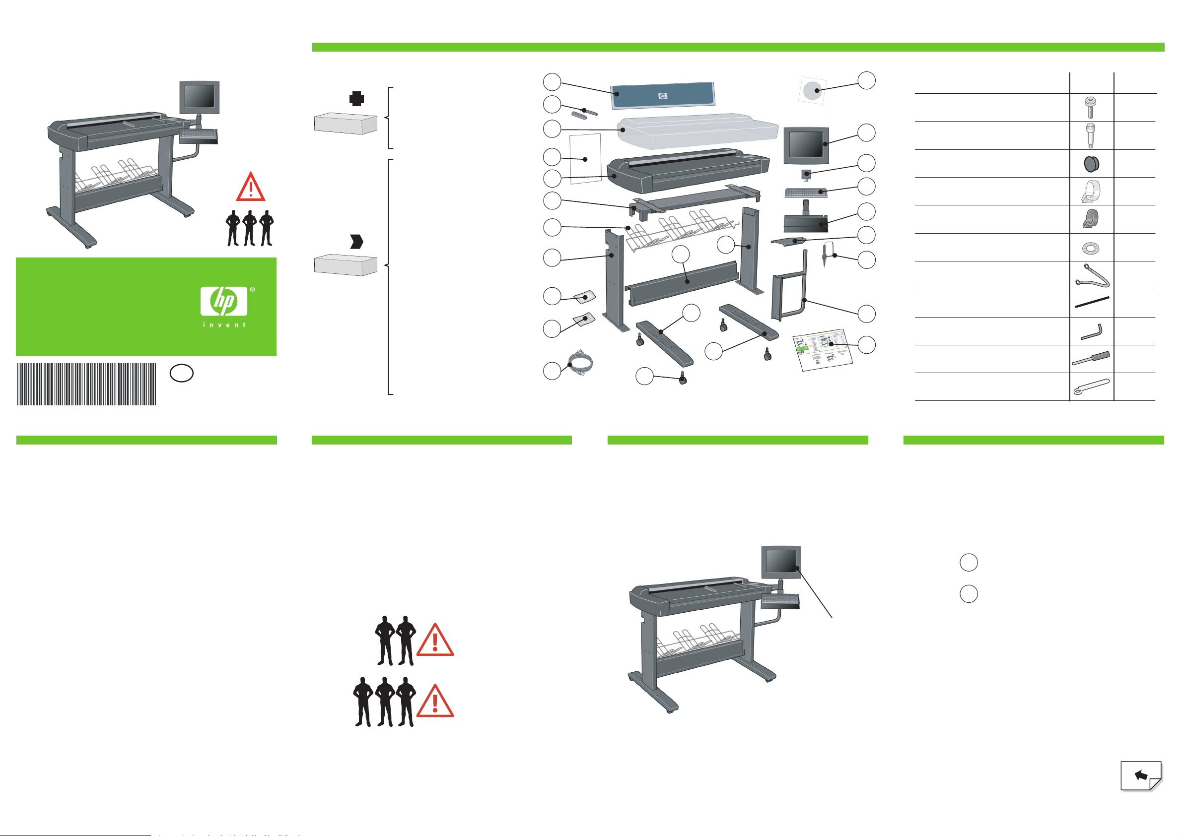
A
HP Designjet 4500
Scanner
Assembly
Instructions
Read these instructions carefully...
and complete each stage before you start the
next.
What you will need to do the job:
Because some of the components of the
scanner are bulky, you will need 2 or 3
people to lift them. See the descriptions that
follow for details, a symbol like this is used:
Touch screen
Assembly
Please note
The touch screen assembly can be mounted on
either the right or the left side of the stand.
Please note
During the stand assembly you will see some reference
to the following symbol labels which appear on some
items, standing for left side, and right side.
4
6
8
24
11
19
21
17
10
9
3
15
2
1
5
7
16
25
13
LRLeft side
Right side
23
18
20
22
Box contents
Maintenance sheet
Media guides (X2)
Plastic dust cover
A2 envelope
Scanner
Top bar
Basket
Left leg
Assembly kit
Maintenance kit
Cable bundle
Wheels (X4)
Left foot
Right foot
Lower bar
Right leg
System recovery DVD
Touch Screen
Monitor joint
Keyboard
Keyboard table
Bracket cover
Touch screen pen
Touch screen bracket
Assembly instructions
Box
Box
1.
2.
3.
4.
5.
6.
7.
8.
9.
10.
11.
12.
13.
14.
15.
16.
17.
18.
19.
20.
21.
22.
23.
24.
25.
Assembly kit contents
Description
Quantity
supplied
34
Allen key T20
Torx 25 key
Spanner for joint
Screw M5×14 (Torx T25) for stand assembly
Special screw for scanner (Torx T20) 5
1
1
1
Large power cable clips
3
Small power cable clips
12
Starwasher 5mm
7
Earth cable
1
Plastic strip
4
Plastic caps
4
14
12
Q1277-90031
EN
Page 3
21 3 4
65 7 8
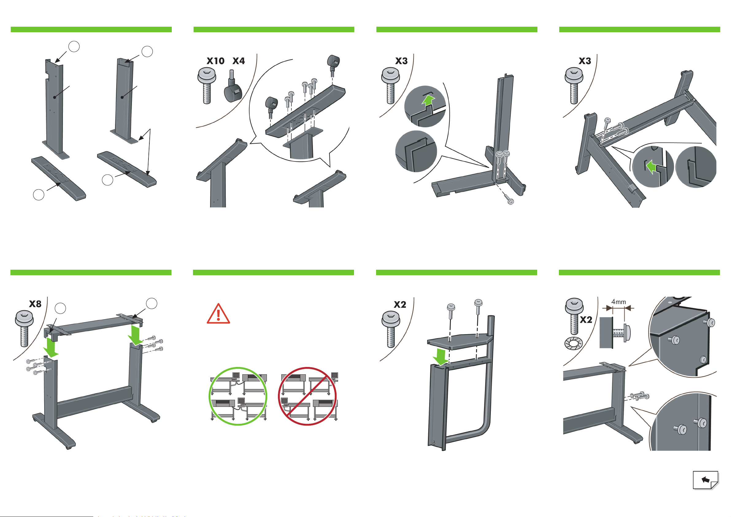
B
Using the letter symbols shown, identify the left and right
legs using the above image. The image is as seen from the
front of the scanner.
Lay one of the legs down and attach the lower bar, hooking
in the tab and fixing with three M5X14 screws.
Attach the lower bar to the other leg, hooking in the tab and
fixing with three M5X14 screws.
Put the two legs upright, and slide the top bar into the legs,
attaching with four M5X14 screws on each leg.
Turn the left and right legs upside down, and attach the feet
and wheels to the legs. Use five M5X14 screws, and two
wheels for each foot.
Longer part
towards
the front
Left leg Right leg
At this point you must decide on which
side you are going to fit the touch
screen assembly. This can be fitted on
the left or right side of the stand.
Please note: If you have a MFP unit or plan to use
your scanner with a printer, the printer must be
placed on the same side as the touch screen.
The next steps, explain how to fit the touch screen
assembly when the touch screen is located on the
right side of the stand.
To fit the touch screen assembly to the left side of
the stand, using the same parts, just ‘mirror’ the
assembly procedure.
L
L
R
R
L
R
Attach the bracket cover to touch screen bracket using two
M5X14 screws.
Loosen the two top screws on the outside of the
leg to leave a 4mm gap. Fix two M5X14 and
two starwashers to the middle two holes on the
outside of the leg. Do not fully tighten the
screws, also leave a 4mm gap.
Page 4
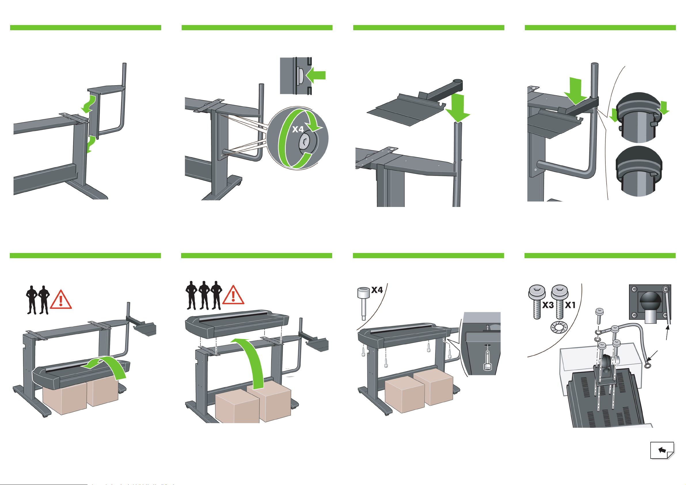
Slide the keyboard table onto the touch screen arm. Push the keyboard table down until the the pointer on the
touch screen arm.
Using 3 people; two to lift, and one to position, lift the
scanner into place locating the rubber feet in the holes
indicated.
Place some packaging boxes, or something about half the
height of the scanner stand in front of the stand, and lift the
scanner up onto them.
With the protective foam in place, put the touch
screen face down and attach the monitor joint
to the rear along with one end of the earth
cable where shown, using four M5×14 screws
and one star washer for the earth cable.
Slide the touch screen bracket assembly down over the 4
screws.
Tighten the 4 screws.
Fix with the four special screws.
109 11 12
1413 15 16
C
Earth cable
Page 5

Remove the protective foam ends, and slide the hub of the
touch screen assembly into the touch screen arm.
Fix the touch screen pen to the side of the touch screen. The unit is now assembled and should appear as in the
above illustration.
Push down the two locks, and open the
scanner cover to expose the scan
area.
Connect the earth cable from the touch screen assembly to
the touch screen arm using a M5X14 screw and
starwasher.
Unfold the bin. From the back of the stand, insert the left and
right arms of the bin into the two slots on the rear of the
legs. Make sure they are fully inserted.
Place the keyboard onto the keyboard table.
Cleaning the scan area...
You are now required to clean the scan area. To
do so you will need the cleaning tools provided in
the maintenance kit and a cleaning fluid (not
included in the maintenance kit).
Caution: do not use abrasives, acetone, benzene,
or fluids that contain these chemicals. Do not
spray liquids directly onto the scanner glass plate
or anywhere else in the scanner.
1817 19 20
2221 23 24
D
Page 6
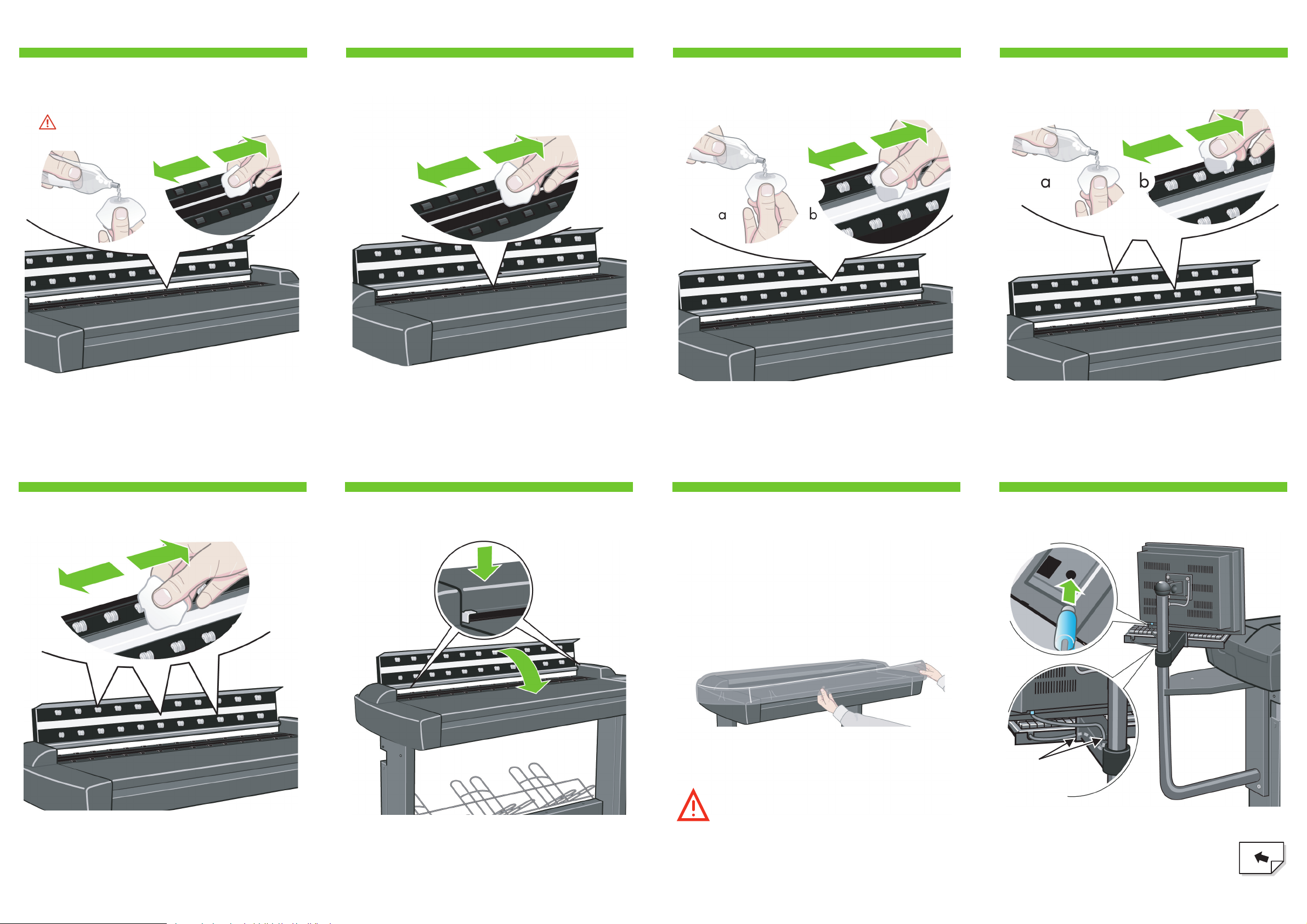
Clean the glass with a lint-free cloth and a mild, streak-free,
glass cleaner.
caution: see note in step 23
2625 27 28
3029 31 32
E
Dry the glass fully using a separate clean, dry lint-free cloth
like the one provided with the maintenance kit.
Clean the white background plate with a lint-free cloth and a
mild, streak-free, glass cleaner.
Clean the transport rollers and surrounding area.
Dry the white background plate, rollers, and surrounding
area fully using a separate clean, dry lint-free cloth.
Close the scanner cover and push down on the top to lock it
into place.
Connect the keyboard to the touch screen,
passing the cable along the inside of the arm
and up through the hole in the keyboard
bracket as shown.
Cable
through
holes.
Keep out dust and reduce maintenance time
Cover your scanner with the plastic dust cover when not
in use.
Caution: make sure the scanner power is OFF when
using the scanner dust cover.
Page 7

3433 35 36
3837 39 40
F
Connect the cable bundle to the touch screen as shown;
inserting the Power, two FireWire, and Network
connections.
Connect the power cable to the scanner. Fit the power cable coming from the scanner
into five clips. Then attach the clips to the stand.
Remove the cover on the side of the scanner, and insert one
of the FireWire cables through the slot at the back.
Fit the protected part of the bundle cable coming from the
screen into two large clips. Attach the clips to the holes in
the underside of the touch screen bracket.
Insert the other end of the FireWire cable into one of the
sockets in the scanner, and replace the cover on the side of
the scanner.
Power
FireWire
Network
Remove the cover from the leg; push up (A), and remove
(B).
Place the excess cables into the slot in the leg.
Make sure that the end of the power cable, the
FireWire and the Network cables are visible as
shown above.
Page 8

4241 43 44
4645 47 48
G
Note: if when switching on the touch screen a ‘not present’
message appears, please press the ‘Rescan’ option on the
touch screen.
Camera alignment & calibration
(height alignment, stitching, basic calibration, and color
calibration)
You are now required to calibrate the scanner. For this you
will need the scanner maintenance sheet, found in the
protective folder shown above.
Replace the cover onto the leg. Connect the power cable extension, and then connect to a
power outlet.
Switch on the scanner and leave it to warm up
for some minutes until the green (ready status)
light appears.
When the green (ready status) light has appeared, switch on
the touch screen.
Important: when setting up for the first time, make sure
that the scanner is turned on for at least one hour
before moving on to the next step of camera alignment
calibration. Slight light intensity changes and camera
shifting can occur just after turning the scanner on, and
warm-up time will ensure that light conditions and
camera heights have stabilized. During this time if you
are installing the MFP unit, go and start the printer
assembly.
To start the maintenance procedure:
a) On the touch screen, press the Setup tab.
b) Press the Scan Options button.
c) Press the Scanner Maintenance button.
1 hour
Page 9

5049 51 52
5453 55 56
H
The maintenance wizard will ask you to insert the
maintenance sheet. The sheet’s printed side must be face
down. Feed the paper in aligning the two midpoint arrows.
Press ‘Next’ to continue.
When the maintenance procedure has completed, remove
the scanner maintenance sheet and return it to its protective
cover. Store the folder in the slot at the front of the stand.
The scanner comes equipped with two magnetic media
guides; these can be placed and moved as required.
Insert two plastic caps in the holes in the touch screen arm. The scanner’s ruler can be changed between
centimeters and inches by sliding it out, turning it over, and
reinserting it.
The scanner is connected to the printer by inserting the
FireWire cable where shown above.
For MFP or if using an
optional printer!
The MFP printer comes with a replacement label
containing support information, this should be
placed over (replace) the existing label found on
the back of the scanner.
Now follow the instructions that appear on the touch screen.
For MFP units only!
Page 10

5857 59 60
For any further information on how to use your
scanner, see the online help system available
from your touch screen using the button below.
I
Keep these instructions
In order to perform routine maintenance (once a
month) you will find it
useful to refer again to the following sections:
• cleaning the scan area
• camera alignment and calibration
To add an HP Designjet printer to the printer list
in your scanner software, follow these steps:
1: On the touch screen go to the setup tab.
2: Press option button and select system.
3: Press the button for the printer you wish to install.
4: Follow the instructions on the screen.
Next, you should check the TCP/IP settings in
your touch screen, and correct them if necessary.
If you intend to scan to the network, with the
HP Designjet scan software, files to be
shared across the network should be placed in
the D:\images directory.
Once a files is saved to this directory it can be
accessed through the network, from any
computer with any operating system.
For more guidance on this issue, see the
user documentation that came with your unit.
Page 11

Printed in
Imprimé en
Stampato in
Hewlett Packard Company
Avenida Graells, 501
08174 Sant Cugat del Vallés
Barcelona
Spain
© Hewlett-Packard Company, 2005
 Loading...