

Page 1
assembly instructions and
routine maintenance procedures
hp designjet scanner 4200
s
y
s
t
e
m
r
e
c
o
v
e
r
y
c
d
r
o
1
m
h
p
d
e
s
i
g
n
j
e
t
c
o
p
i
e
r
c
c
8
0
0
p
s
2
s
designjet copier cc800p
hp
18
17
16
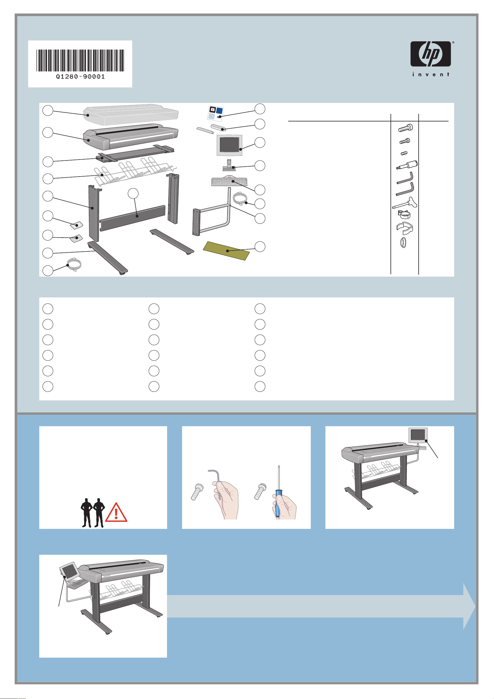
screw M5×14 (Torx T25) for stand assembly
screw M4×8 for keyboard table and touch screen
screw M3×8 for touch screen bracket
3
15
4
5
10
14
13
6
12
special screw for scanner 4
Allen key 2.0mm for keyboard table and touch screen 1
Allen key 2.5mm for touch screen bracket
Torx 25 key
power cable clips
wire routing clips
7
plastic caps
assembly kit contents
description quantity
20
5
1
1
1
12
5
4
11
8
9
1
plastic dust cover
2
scanner
3
top bar
4
basket
5
leg (×2)
6
maintenance kit
7
8
9
10
11
12
read these instructions carefully...
and complete each stage before you start the
next.
what you will need to do the job
Because some of the components of the
scanner are bulky, you will need 2 or 3
people to lift them. See the descriptions that
follow for details, a symbol like this is used:
assembly kit
feet (×2)
power cables
lower bar
scanner maintenance sheet
touch screen arm
a note about fixings
When initially assembling the scanner stand
do not fully tighten the screws; you will be
asked to do this later.
13
FireWire cable
14
keyboard table
15
touch screen bracket
16
touch screen
17
media guides (×2)
18
system recovery CD-ROM
touch screen
assembly
touch screen
assembly
please note
The touch screen assembly can be mounted on
either the right or the left side of the stand.
please note
The touch screen assembly can be mounted on
either the right or the left side of the stand.
1
Page 2
left leg
tabs
right leg
cut
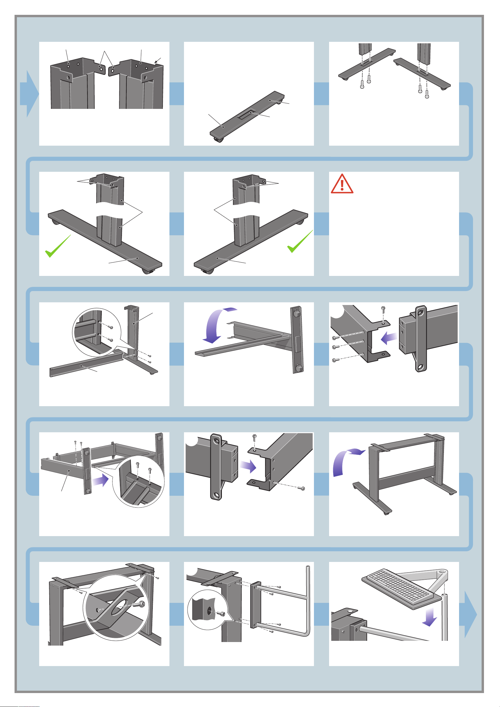
In step 1 you will attach the left and right feet to
the left and right legs.
Each foot has a slot for the leg. This slot is not in
the center of the foot. When you attach the leg,
make sure the shorter length of the foot is at the
front.
1
Identify the left and right legs. They are slightly
different in shape at the top of the leg. The right
leg has a small cut at the top.
tabs
right leg
shorter length
at the front
shorter length
at the front
left leg
slot
shorter length
at the front
tabs
foot
Attach the feet to the left and right legs using
four M5×14 screws (two for each foot). Tighten
the screws with the Torx key found in the
assembly kit. Make sure the tabs at the top of
each leg face in towards the middle of the
assembly.
At this point you must decide on which
side you are going to fit the touch
screen assembly. This can be fitted on
the left or right side of the stand.
The next steps, 2 to 15, explain how to fit the
top bar and the touch screen assembly when the
touch screen is located on the right side of the
stand.
To fit the touch screen assembly to the left side of
the stand, using the same parts, just ‘mirror’ the
assembly procedure.
2
cross bar
Slide the cross bar into the slot on the left leg and
secure with two M5×14 screws using the Torx
key.
left leg
3
Lay the left leg and cross bar down into the
position shown.
65 7
4
Slide the top bar onto the left leg and s
four M5×14 screws using the
position of the screw holes.
Torx key. Note the
ecure with
right leg
Slide the right leg onto the cross bar and top bar.
Secure the cross bar to the right leg using two
M5×14 screws and the Torx key.
8
Secure the front of the top bar using two
M5×14 screws and the Torx key.
Attach the right side of the top bar to the top of
the right leg and secure with two M5×14 screws.
Use only the two screws shown above.
Raise the stand assembly carefully into the upright
position.
910
Attach the touch screen arm to the right leg using
four M5×12 screws.
Slide the keyboard assembly down as far as it
will go on the touch screen arm.
2
Page 3

E
E
X
T
E
N
D
E
D
E
X
I
T
E
X
I
T
N
O
R
M
A
L
E
X
T
E
N
D
E
D
N
O
R
M
A
L
I
n
c
h
e
s
m
m
0
.
6
3
0
.
5
5
0
.
4
7
0
.
3
9
0
.
3
1
0
.
2
4
0
.
1
6
0
.
0
8
1
6
1
4
1
2
1
0
8
6
4
2
E
X
T
E
N
D
E
D
E
X
I
T
E
X
I
T
N
O
R
M
A
L
E
X
T
E
N
D
E
D
N
O
R
M
A
L
I
n
c
h
es
m
m
0
.
6
3
0
.
5
5
0
.
4
7
0
.
3
9
0
.
3
1
0
.
2
4
0
.
1
6
0
.
0
8
1
6
1
4
1
2
1
0
8
6
4
2
E
X
T
E
N
D
E
D
E
X
I
T
E
X
I
T
N
O
R
M
A
L
E
X
T
E
N
D
E
D
N
O
R
M
A
L
I
n
c
h
e
s
m
m
0.63
0.
55
0.
47
0.3
9
0.3
1
0.
2
4
0.
1
6
0.0
8
1
6
1
4
1
2
1
0
8
6
4
2
E
X
T
E
N
D
E
D
E
X
I
T
E
X
I
T
N
O
R
M
A
L
E
X
T
E
N
D
E
D
N
O
R
M
A
L
I
n
c
h
e
s
m
m
0.63
0.55
0.47
0.3
9
0.3
1
0.2
4
0.1
6
0.0
8
1
6
1
4
1
2
1
0
8
6
4
2
11
12
13
Lock the keyboard assembly to the touch screen
arm using one M4×8 screw.
14
Attach with three more M4×8 screws as shown.
Lift the scanner into place, locating the rubber
feet in the holes indicated, and fixing with the
four special screws.
Rest the touch screen face down on a table.
Attach the touch screen bracket to the rear of the
touch screen using two M4×8 screws as shown.
15 16
Slide the hub of the touch screen assembly into
the touch screen arm.
Secure the hub of the touch screen bracket using
an M3×8 screw.
17
Unfold the bin. Insert the left and right arms of
the bin into the two slots on the rear of the legs.
Make sure they are fully inserted.
19
E
X
T
E
N
D
E
E
X
I
D
T
6
1
4
1
2
N
1
0
1
O
8
R
6
4
M
2
A
m
L
m
3
6
5
.
5
7
0
.
4
9
0
.
3
1
0
.
3
4
E
0
.
E
2
6
0
X
.
s
X
1
I
8
0
T
.
e
0
T
0
.
E
h
0
N
c
D
n
I
E
D
N
O
R
M
A
L
L
A
M
R
O
N
D
m
E
m
D
N
T
2
I
E
4
X
T
6
E
X
8
0
E
1
2
1
4
1
6
1
s
e
h
c
8
L
In
0
6
.
A
1
4
0
.
M
2
1
0
.
R
3
9
0
.
3
7
O
0
.
4
5
0
N
.
5
3
0
.
6
T
0
.
I
0
D
X
E
E
D
N
E
T
X
E
18
The unit is now assembled and should appear
as in the above illustration.
20 21
cleaning the scan area...
You are now required to clean the scan
area. To do so you will need the cleaning
tools provided in the maintenance kit and a
cleaning fluid (not included in the
maintenance kit).
Caution: do not use abrasives, acetone,
benzene, or fluids that contain these
chemicals. Do not spray liquids directly
onto the scanner glass plate or anywhere
else in the scanner.
E
X
T
E
N
D
E
E
X
I
D
T
6
1
4
1
2
N
1
0
1
O
8
R
6
4
M
2
A
m
L
m
5
5
0.63
.
47
9
0
.
1
0
.3
E
4
0
.3
E
2
6
X
0
.
X
s
1
I
8
0
T
.
e
T
0
.0
E
h
0
N
c
D
n
I
E
D
N
O
R
M
A
L
Open the scanner cover to expose the scan
area.
E
X
T
E
N
D
E
E
X
I
D
T
6
1
4
1
2
N
1
0
1
O
8
R
6
4
M
2
A
m
L
m
3
6
5
.
5
7
0
.
4
9
0
.
3
1
0
.
3
4
E
0
.
2
E
6
0
X
.
X
1
I
8
0
T
.
es
0
T
0
.
E
h
0
N
D
nc
I
E
D
N
O
R
M
A
L
A
M
R
O
N
D
m
E
m
D
N
2
T
I
E
4
X
T
6
E
X
8
0
E
1
2
1
4
1
6
1
s
e
h
c
L
8
n
I
0
6
.
A
1
4
0
.
M
2
1
0
.
R
3
9
0
.
3
O
7
0
.
4
5
N
0
.
5
3
0
.
6
T
0
.
I
0
D
X
E
E
D
N
E
T
X
E
L
Position your fingers in the four lock slots (two at
each end of the platen indicated by the green
arrows above), and press down (blue arrows).
23 2422
caution: see note after step 18
L
A
M
R
O
N
D
m
E
m
D
N
2
T
I
E
4
X
T
6
E
X
8
0
E
1
2
1
4
1
6
1
s
e
h
c
L
8
n
I
6
.0
A
1
4
0
M
2
1
0.
R
3
9
0.
.
7
O
0
4
0.3
N
55
3
0.
T
0.
.6
I
0
D
X
E
E
D
N
E
T
X
E
With the platen pushed down, slide the two locks
inwards until the pins at either end pop up,
locking the platen open and ready to be removed.
Dry the glass fully using a separate clean, dry
Raise the two handles, and remove the pressure
platen.
Clean the glass with a lint-free cloth and a mild,
streak-free, glass cleaner.
3
lint-free cloth like the one provided with the
maintenance kit.
Page 4

E
X
T
E
N
D
E
D
E
X
I
T
E
X
I
T
N
O
R
M
A
L
E
X
T
E
N
D
E
D
N
O
R
M
A
L
I
n
c
h
e
s
m
m
0
.6
3
0
.
5
5
0
.
47
0
.
3
9
0
.3
1
0
.
24
0
.
1
6
0
.
0
8
1
6
1
4
1
2
1
0
8
6
4
2
E
X
T
E
N
D
E
D
E
X
I
T
E
X
I
T
N
O
R
M
A
L
E
X
T
E
N
D
E
D
N
O
R
M
A
L
I
n
c
h
e
s
m
m
0
.
6
3
0
.
5
5
0
.
4
7
0
.
3
9
0
.
3
1
0
.
2
4
0
.
1
6
0
.
0
8
1
6
1
4
1
2
1
0
8
6
4
2
T
E
X
T
E
N
D
E
D
E
X
I
T
E
X
I
T
N
O
R
M
A
L
E
X
T
E
N
D
E
D
N
O
R
M
A
L
In
c
h
e
s
m
m
0
.
6
3
0
.
5
5
0
.
4
7
0
.
3
9
0
.
3
1
0
.
2
4
0
.
1
6
0
.
0
8
1
6
1
4
1
2
1
0
8
6
4
2
E
X
T
E
N
D
E
D
E
X
I
T
E
X
I
T
N
O
R
M
A
L
E
X
T
E
N
D
E
D
N
O
R
M
A
L
I
n
c
h
e
s
m
m
0
.
6
3
0
.
5
5
0
.
4
7
0
.
3
9
0
.
3
1
0
.
2
4
0
.
1
6
0
.
08
1
6
1
4
1
2
1
0
8
6
4
2
25
E
X
T
E
N
D
E
E
X
I
D
T
6
1
4
1
2
N
1
10
O
8
R
6
4
M
2
A
m
L
m
3
.6
55
0
.
47
9
0
.
3
1
0
3
4
E
0.
2
E
6
0.
X
X
s
I
1
8
0.
T
e
T
0.
E
h
0.0
N
c
D
n
I
E
D
N
O
R
M
A
L
L
A
M
R
O
N
D
m
E
m
D
N
2
T
I
E
4
T
X
6
E
X
8
E
10
2
1
14
6
1
s
e
h
c
L
n
8
I
0
.
A
16
0
.
M
24
1
0
.
R
3
9
0
.
3
7
O
0
.
4
5
0
N
.
5
3
0
.
6
T
0
.
I
0
D
X
E
E
D
N
E
T
X
E
ab
a
Turn the pressure platen over to expose the white
background plate.
28
Dry the white background plate, rollers, and
surrounding area fully using a separate clean,
dry lint-free cloth.
Clean the white background plate with a lint-free
cloth and a mild, streak-free, glass cleaner.
29
Replace the pressure platen and lower the two
handles.
Clean the transport rollers and surrounding area.
30
ba
X
E
L
A
M
R
O
N
D
m
E
m
D
N
2
T
I
E
4
X
T
6
E
X
8
0
E
1
2
1
4
1
6
1
s
e
ch
L
8
n
I
0
6
.
A
1
4
0
.
M
2
1
0
.
R
3
9
0
.
3
O
7
0
.
4
5
0
N
.
5
3
0
.
6
T
0
.
I
0
D
X
E
E
D
N
E
T
X
E
L
A
M
R
O
N
D
m
E
m
D
N
2
T
I
E
4
X
T
6
E
X
8
0
E
1
2
1
4
1
6
1
s
e
h
c
L
8
In
6
A
1
4
0.0
.
M
1
0
.2
R
3
9
0
O
0.
47
5
0.3
N
0.
T
0.5
.63
I
0
D
X
E
E
D
N
E
T
X
E
Pushing downwards on the left side of the
pressure platen, push in the pin (a) and slide in
the lock (b) locking the platen end into place.
31
a
X
E
b
L
A
M
R
O
N
D
m
E
m
D
N
2
T
I
E
4
X
T
6
E
X
8
0
E
1
2
1
4
1
6
1
s
e
h
c
L
8
n
I
6
.0
A
1
4
0
M
2
1
0.
R
9
0.
.3
3
7
O
0
.
4
0
N
55
3
0.
.
T
0
.6
I
0
D
X
E
E
D
N
E
T
X
E
E
X
T
E
N
D
E
E
X
I
D
T
6
1
4
1
2
N
1
0
1
O
8
R
6
4
M
A
2
m
L
m
3
6
5
.
5
7
0
.
4
9
0
.
3
1
0
.
3
E
4
0
.
E
6
X
0
.2
X
1
I
8
T
0
.
es
0
T
0
.
E
h
0
N
c
D
n
I
E
D
N
O
R
M
A
L
Pushing downwards on the right side of the
pressure platen, push in the pin (a) and slide in
the lock (b) locking the platen end into place.
33
32
keep out dust and reduce maintenance
time
Cover your scanner with the plastic dust cover
when not in use.
ps
0
80
c
r c
e
i
p
o
c
t
e
j
ign
s
e
d
p
h
Caution: make sure the scanner power is
With the platen firmly locked into place, close
the scanner cover.
OFF when using the scanner dust cover.
34 35
If you have mounted the touch screen assembly on
the right leg you will find that the FireWire cable
Connect the touch screen to the scanner using the
FireWire cable, fastening with the clips on the
touch screen arm.
36
is longer than needed. Please keep the cable
bundled. You will attach this bundled cable to a
clip later.
37
Connect the keyboard to the touch screen.
38
Attach the "Y" power cable into the clips on the
Connect the ‘Y’ power cable to the touch screen.
Connect the ‘Y’ power cable to the scanner.
touch screen arm.
4
Page 5

39 40
41
Fit the ‘Y’ power cable into the clips. Then attach
the clips to the stand.
42
Connect the ‘Y’ power cable to a power outlet.
Fit the ‘Y’ power cable and the bundled FireWire
cable into the clip. Then attach the clip to the
stand.
camera alignment & calibration
(height alignment, stitching, basic calibration,
and color calibration)
You are now required to calibrate the scanner.
For this you will need the scanner maintenance
sheet, found in the protective folder shown below.
If the touch screen assembly has been mounted
on the left, the ‘Y’ power cable should be
attached only to the left leg and the cross bar.
43
Switch on the scanner and leave it to warm up
for some minutes until the green (ready status)
light appears.
44
When the green (ready status) light has
appeared, switch on the touch screen.
45
Note: if when switching on the touch screen a
‘not present’ message appears, please press the
‘Rescan’ option on the touch screen.
Important: make sure that the
scanner is turned on for at least one
hour before moving on to the next step
of camera alignment calibration. Slight
light intensity changes and camera
shifting can occur just after turning the
scanner on, and warm-up time will
ensure that light conditions and camera
heights have stabilized.
1 hour
4746
To start the maintenance procedure:
a) On the touch screen, press the Setup tab.
b) Press the Scan Options button.
c) Press the Scanner Maintenance button
(shown above).
48
When the maintenance procedure has
completed, remove the scanner maintenance
sheet and return it to its protective cover. Store
the folder in a dry place away from light.
The maintenance wizard will ask you to insert the
maintenance sheet. The sheet’s printed side must
be face down. Feed the paper in aligning the
two midpoint arrows. Press ‘Next’ to continue.
The scanner comes equipped with two magnetic
media guides; these can be placed and moved
as required.
Now follow the instructions that appear on the
touch screen.
Insert the plastic caps in the holes in the touch
screen arm.
5
Page 6

The scanner’s ruler can be changed between
centimeters and inches by sliding it out, turning it
over, and reinserting it.
2
9
93
94
95
96
97
98
91
2
9
93
0
Inches
40
Inches
87
88
89
90
D
N
I
E
X
T
E
X
E
4
1
6
1
83
4
8
85
6
8
L
A
M
R
O
N
D
m
E
m
T
2
4
6
8
0
1
2
1
s
e
h
c
8
L
In
0
6
.
A
4
0
.1
M
2
1
0
.
R
3
9
0
.
3
7
O
0
.
5
0
N
.4
5
3
0
.
6
T
0
.
I
0
D
X
E
E
D
N
E
T
X
E
When System Administrators configure your
system in a network domain, they will also need
to set up automatic login. This procedure is
documented in “how do I set up automatic
login” in your online help.
To connect your scanner to a network, first
connect the network cable to the Ethernet socket
at the back of your touch screen as shown.
To add an HP Designjet printer to the printer list
in your scanner software, follow these steps:
1. On the touch screen, press the
Quit button and then the Exit
button to exit the scanner
software.
2. Press the System Setup button.
Next, you should check the TCP/IP settings in
your touch screen, and correct them if necessary.
If you intend to scan to the network, you will also
need to create a workgroup. You may want to
share the Images folder in your touch screen so
that it can be accessed from elsewhere on the
network. For more guidance on these steps, see
the online help system.
For any further information on how to use your
scanner, see the online help system available
from your touch screen using the button below.
1
2
3
4
5
6
7
8
9
1
plastic dust cover
2
scanner
3
top bar
4
basket
5
leg (×2)
6
maintenance kit
read these instructions carefully...
and complete each stage before you start the
next.
what you will need to do the job
Because some of the components of the
scanner are bulky, you will need 2 or 3
people to lift them. See the descriptions that
follow for details, a symbol like this is used:
touch screen
assembly
please note
The touch screen assembly can be mounted on
either the right or the left side of the stand.
assembly instructions and
routine maintenance procedures
hp designjet scanner 4200
s
y
s
te
m
r
e
c
o
v
e
r
y
c
d
r
o
m
h
p
d
e
s
i
g
n
j
e
t
c
o
p
i
e
r
c
c
8
0
0
p
s
s
p
0
0
8
c
c
r
e
i
p
o
c
t
e
j
n
g
i
s
e
d
p
h
10
7
assembly kit
8
feet (×2)
9
power cables
10
lower bar
11
scanner maintenance sheet
12
touch screen arm
a note about fixings
When initially assembling the scanner stand
do not fully tighten the screws; you will be
asked to do this later.
1
assembly kit contents
18
description quantity
17
screw M5×14 (Torx T25) for stand assembly
screw M4×8 for keyboard table and touch screen
16
screw M3×8 for touch screen bracket
special screw for scanner 4
15
Allen key 2.0mm for keyboard table and touch screen 1
Allen key 2.5mm for touch screen bracket
14
Torx 25 key
13
power cable clips
12
wire routing clips
plastic caps
11
13
FireWire cable
14
keyboard table
15
touch screen bracket
16
touch screen
17
media guides (×2)
18
system recovery CD-ROM
please note
The touch screen assembly can be mounted on
either the right or the left side of the stand.
3. Press the Install HP Designjet button.
4. Follow the instructions on the screen.
20
5
1
1
1
12
5
4
keep these instructions
In order to perform routine maintenance (once a month) you will find it
useful to refer again to the following sections:
touch screen
assembly
• cleaning the scan area: steps 19 to 32
• camera alignment and calibration: steps 43 to 48
You can also find these steps described in the online help topic
how do I... maintenance procedures and on the using your scanner CD.
not for resale
© 2003 Hewlett-Packard Company
all rights reserved
printed in
Q1280-90001
6
 Loading...