

Page 1
HP Designjet 3D Removal System
Service Guide
Page 2

Legal Notice
© 2012 Hewlett-Packard Development
Company, L.P.
The information contained herein is subject
to change without notice.
The only warranties for HP Products and services
are set forth in the express warranty statement
accompanying such products and services.
Nothing herein should be construed as
constituting an additional warranty.
HP shall not be liable for technical or editorial
errors or omissions contained herein.
Conforms to ANSI/UL std. 60950-1-2003
Certified to CAN/CSA C22.2 no. 60950-1-03
conform with the following standards, in accordance with the
EU Machinery, Low Voltage and Electromagnetic
HP Designjet 3D Removal System
Compatibility Directives.
.
Page 3

Introduction
The HP Designjet 3D Removal System is specifically developed to provide
efficient removal of support material from a model. The system removes support material by immersing models in a bath of water with a specific amount
of cleaning agent bags added to the cleaning agent receptacle.
Welcome to the new dimension of HP Designjet 3D Removal System!
How to use this guide
This Service Guide is laid out in easy to follow sections that cover Set-up,
Operation, Maintenance, and Troubleshooting. Read each section carefully
so that you will get the best performance from your HP Designjet 3D
Removal System.
3
Page 4
Safety
The following classifications are used throughout this guide.
CAUTION: Indicates a potentially hazardous situation
which, if not avoided, may result in minor or
moderate injury.
WARNING: Indicates a potentially hazardous situation
which, if not avoided, could result in serious injury.
Recycle: Use proper recycling techniques for materials and
packaging.
ESD: Use standard electrostatic
discharge (ESD) precautions
when working on or near
electrical components.
4
Page 5

Table of Contents
Introduction
How to use this guide .....................................................................page 3
Safety ............................................................................................page 4
<> <>
System Overview
How the system works ...................................................................page 7
Setup
Connecting the system ....................................................................page 9
Operation
Cleaning Models ..........................................................................page 11
Other information ........................................................................page 15
Maintenance
Inspecting and cleaning the strainer ..............................................page 17
Cleaning .................................................................................... ..page 17
Model bag ...................................................................................page 17
Troubleshooting
Troubleshooting ...........................................................................page 19
Non-Coded Error Conditions ..........................................................page 19
Error Detection .............................................................................. page 21
Diagnostic and Test Specifications ................................................. page 25
Functional Description ....................................................................page 25
Subtest details ...............................................................................page 29
Service Procedures
Maintenance Preparation .............................................................page 32
Cabinet Components ....................... ....... ....... ....... ....... ........ ......... page 34
5
Page 6

System Lid ....................................................................................page 34
Lower Housing Assembly ................................................................page 36
Upper Housing Assembly ............................................................... page 38
Hardware Components ................................................................page 39
Back Panel ...................................................................................page 39
Line Filter ......................................................................................page 44
Thermostat .................................................................................... page 45
Thermometer Board ....................................................................... page 47
User Interface Board ...................................................................... page 49
Power Entry Module ......................................................................page 52
Main Control Board .......................................................................page 54
Cleaning Tank Assembly ................................................................page 60
Agitation Assembly ........................................................................page 65
Drive Belt .....................................................................................page 68
Induction Motor Assembly ..............................................................page 70
Float Level Sensor Assembly ...........................................................page 72
Lid Switch Assembly ......................................................................page 74
Lid Lock Assembly .........................................................................page 76
Appendix
System Components .....................................................................page 80
Upper Components ......................................................................page 81
Internal Components .................................................................. ..page 82
6
Page 7
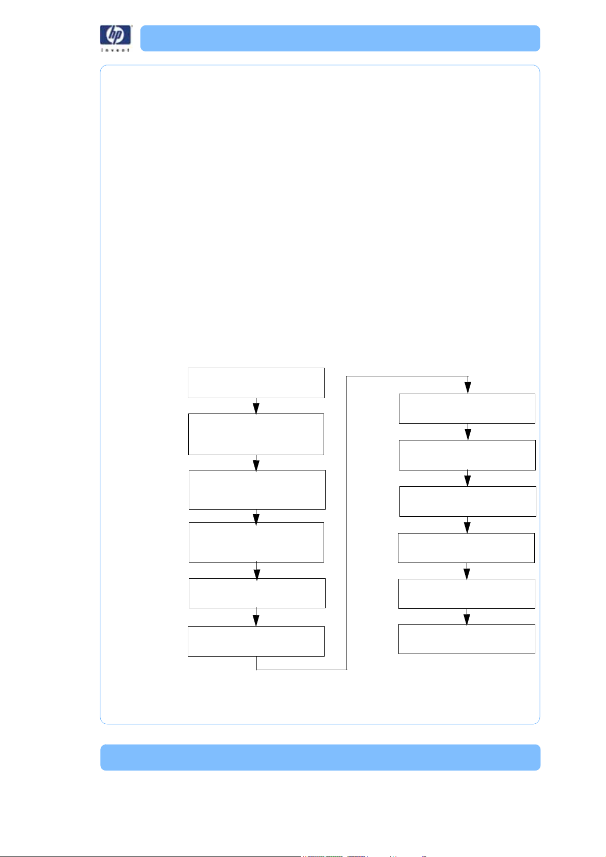
System Overvie w
Place model(s) in model basket
Select:
Cleaning tank level
Cycle length
Lid locks
Drain
Rinse cycle
Drain
Lid unlocks
Remove model(s)
Power on the System
Pour in all the contents of the
cleaning agent bag(s)
Press start cycle button
Wash cycle
How the system works
The system removes support material by immersing models in a bath of
water with a specific amount of cleaning agent bags added to the cleaning
agent receptacle. The system heats and circulates solution around the models
in the cleaning tank. The solution dissolves the support material without
harming the underlying model material. Over time, depending on geometry
and the amount of support material, all the support material is dissolved and
the models are ready to be removed, dried and used for their intended purpose.
The system incorporates the following functions:
•Automatic water fill
• User selectable cleaning tank level (half or full)
• Automatic water drain
• Automatic timing device for user selectable short, medium, or long cycles
• Automatic lock/unlock before and after cycling
• Automatic rinse and drain cycle
Figure 1: Sequence of Operation
7
Page 8

8
Page 9

Setup
Connec ting the system
Make sure the following preparations of the physical site are met:
• The system must be placed on a flat and stable surface able to support
36 kg (80 lbs.) to avoid the risk of falling.
• The work area for unpacking the system should be 76.2 cm (30 in.) high,
76.39 cm (28.5 in.) wide and 69.95 cm (27 in.) deep.
• The system must be located at least 20 cm (8 in.) higher than the wastewater drain.
• The drain facility must accept a drain pH level between 6.5 and 10.0.
• The drain must accept a wastewater temperature of at least 75°C (167°F).
• The water source connection must have a 3/4 in. hose thread.
• The water source temperature must be ≥15 ° C ( 59 ° F ) .
A hot water connection is highly recommended to speed up heating, but
is not required.
• The water pressure must be between 0.5 bars and 10 bars (7.25 psi and
145 p s i ) .
• The water source hardness should be ≤300 ppm.
• The grounded electrical outlet (220–240V~ 9A 50 Hz 1200W) must connect to either a Euro or a UK power cord plug provided and must be
located within 2 m (5 ft.) of the system.
• The operating environmental temperature must be between 15°C to 30°C
(59°F to 86°F).
• The operating environmental humidity must be between 20% to 80%,
non condensing.
• Consult your area's requirements regarding the disposal of the HP
Designjet 3D Removal System effluent prior to use. A permit or form of
pre-treatment may be required in your area.
9
Page 10
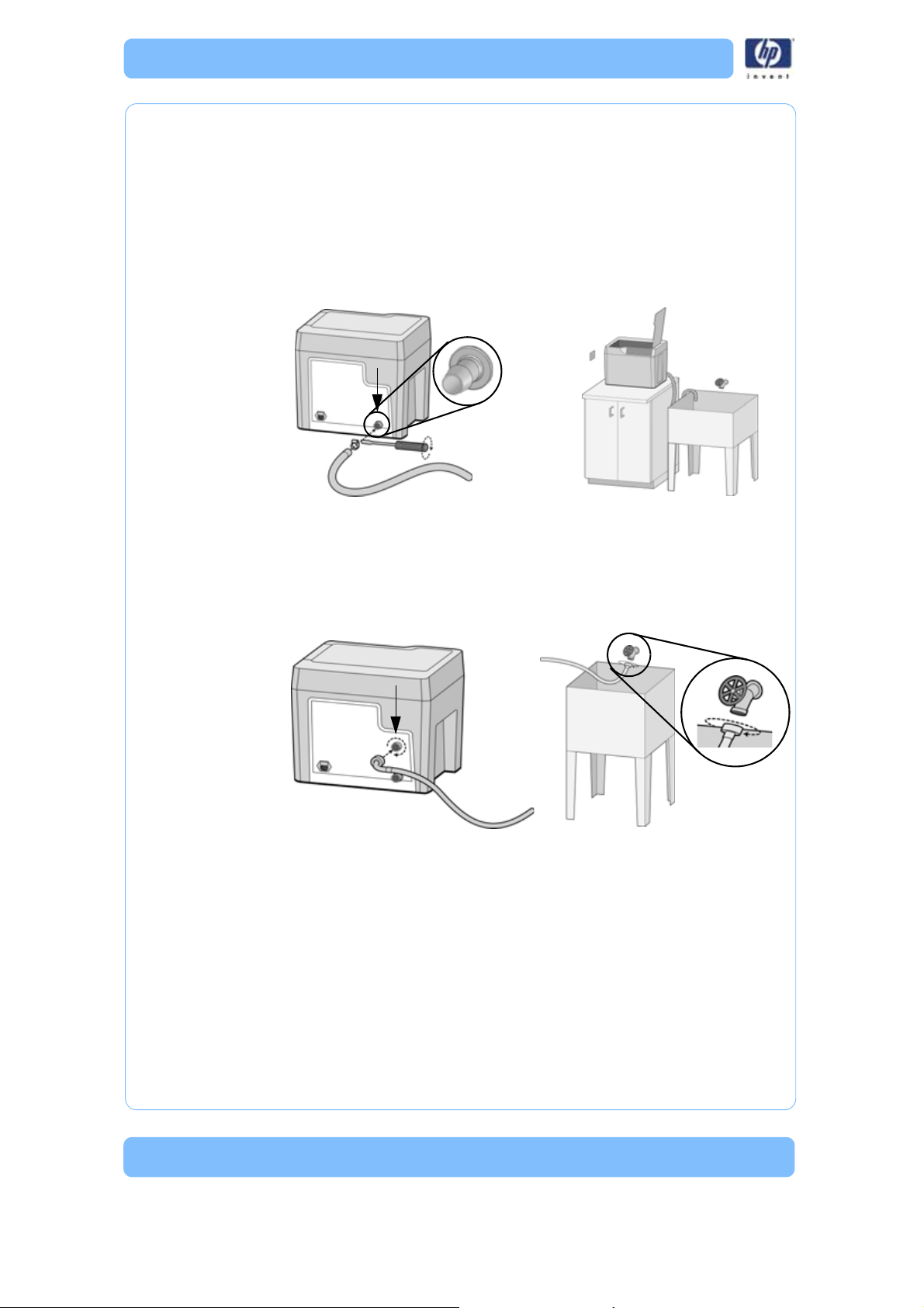
Connect the drain hose
Make sure the drain hose is attached by pushing the end of the drain hose
onto the barbed connection on the back panel of the system. Secure the
hose with the hose clamp using a flat bladed screwdriver. Route the free end
of the drain hose to the wastewater location. Make sure the system is at least
20 cm (8 in.) above the drain hose discharge and there are no kinks in the
hose. The system relies on gravity to drain the wastewater from the cleaning
tank.
Figure 2: Drain hose connections
Connect the water hose
Screw on the end of the water supply hose to the back panel of the system.
Securely tighten the fitting clockwise. Turn on the water and make sure there
are no leaks.
Figure 3: Water hose connections
Plug in the system
Securely plug one end of the supplied power cord into the receptacle at the
back of the system and the other end of the power cord into a grounded
receptacle. Only use the power cord provided.
10
Page 11
Operation
Upper Lid Position
Lower Lid Position
Cleaning Models
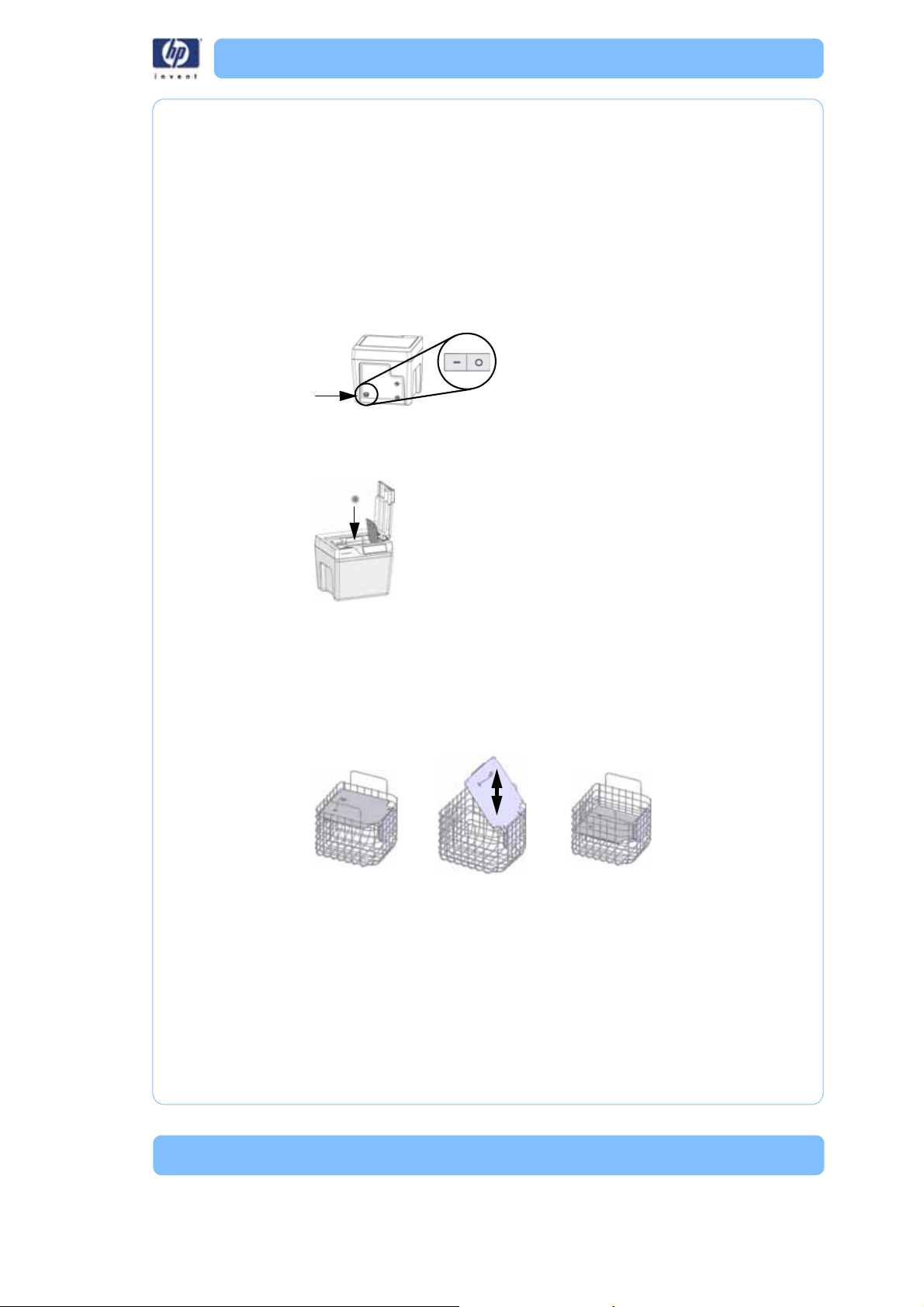
Power on the system
Power on the system using the On/Off switch above the power cord receptacle on the back of the system.
Add models
All models must be placed in the model basket and the model lid adjusted.
The model basket lid ensures the models remain submerged during the
cleaning process. The lid can be adjusted to two heights.
• Use the upper lid position for larger models > 8.89 cm (3.5 in.).
• Use the lower lid position for smaller size models ≤ 8.89 cm (3.5 in.).
• Many models may be cleaned at one time as long as they are submerged during the cleaning process with the model basket lid in either
position.
Delicate and flat models should be placed in the model bag on the model
basket lid. When using the model bag, always select the lower lid position
and do not add other models to the model basket.
• Delicate models have features with a cross sectional areas under 19
sq. mm (0.03 sq. in.).
• Flat models have large flat areas that are greater than 64 mm x 64
mm (2.5 in x 2.5 in) and less than 3 mm (1/8 in) thick).
11
Page 12
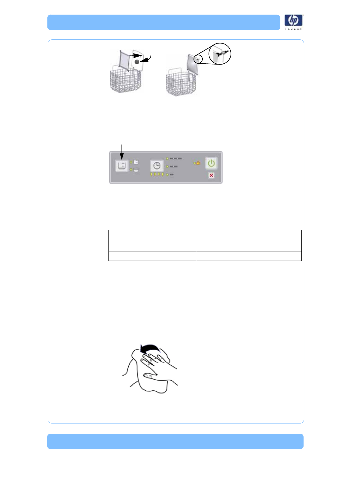
Cleaning tank level
Based on the model lid position, select either a full (upper lid position) or
half (lower lid position) cleaning tank level by pressing the cleaning tank
level button. A full cleaning tank level is approximately 15.14 L (4 gals.) and
a half cleaning tank level is approximately 7.57 L (2 gals).
Cleaning agent bag(s)
Select the number of cleaning agent bag(s) to be used based on Table 1
below.
Table 1: Cleaning Tank Level and Cleaning Agent Bags
Cleaning Tank Level Cleaning Agent Bag
Half cleaning tank level 1 cleaning agent bag
Full cleaning tank level 2 cleaning agent bags
Note:
Do not use more than the specified amount of cleaning agent
bags. Doing so will exceed pH levels for wastewater dis-
posal.
Add cleaning agent bag
Follow the instructions below for adding the contents of the cleaning agent
bag(s) to the cleaning agent receptacle.
1. Dry hands before opening the cleaning agent bag.
12
Page 13
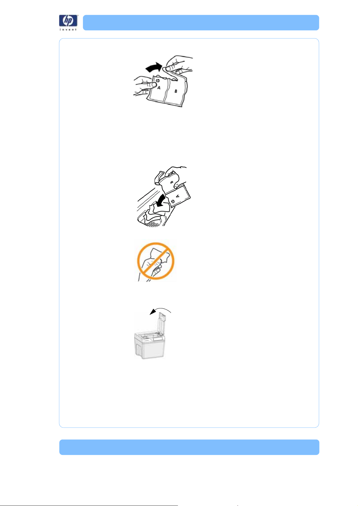
2. Open the cleaning agent bag as shown.
3. Empty all the contents of the specified number of cleaning agent
bag into the cleaning agent receptacle as directed (see
<Reference>Table 1).
Note:
Do not use more than the specified amount of cleaning agent
bags. Doing so will exceed pH levels for wastewater dis-
posal.
4. Avoid handling the contents of the cleaning agent bag.
After adding all the contents of the cleaning agent bag(s), properly dispose
of bag(s) and close the system lid.
13
Page 14
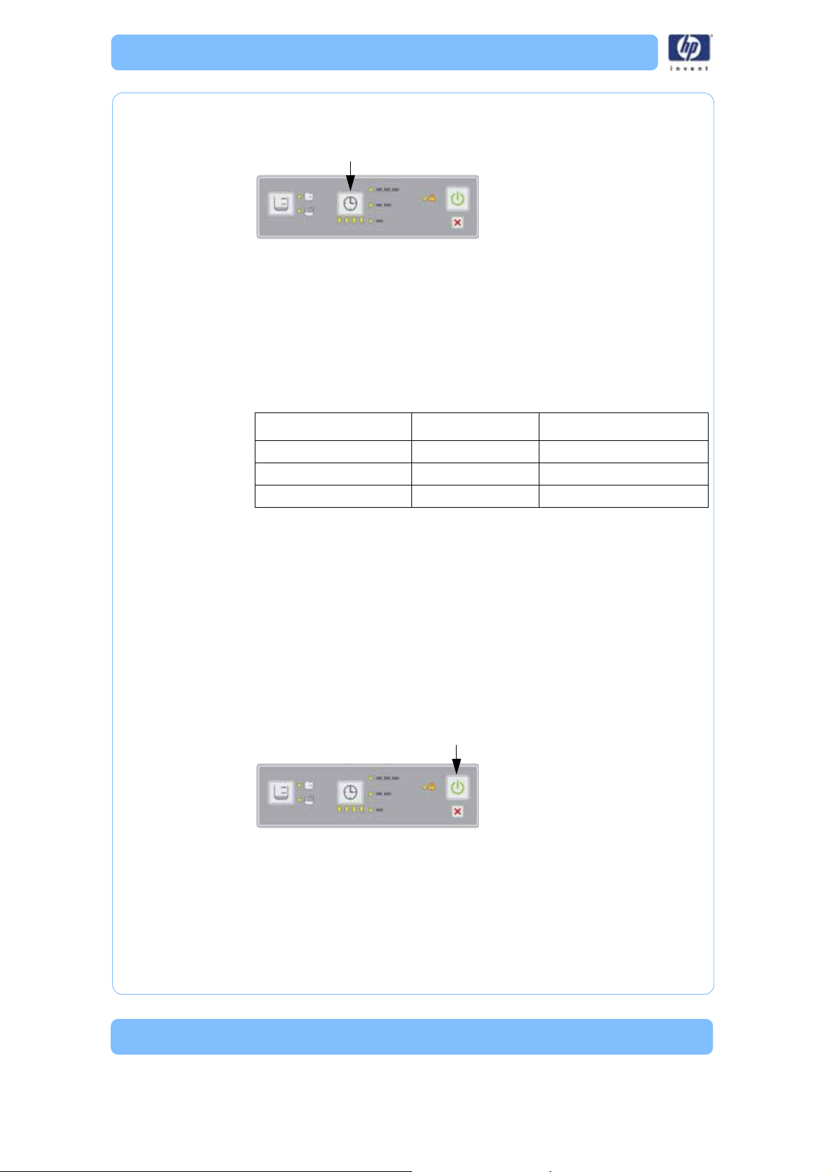
Cycle Length
Select one of the three cycle lengths by pressing the cycle length button.
Each press of the cycle length button increases from a short cycle to a
medium cycle or to a long cycle length. Pressing the cycle length button once
more returns to the short cycle length.
Table 2 should also be used as a general guideline for selecting cycle
lengths for most models.There are some factors that cause the support
removal process to take longer such as model geometry, small support filled
crevices, small blind holes, or low water temperature coming into the system.
Table 2: Cycle Length Settings
Combined Build Times Cycle Selection Approximate Cycle Times
≤ 4 hrs. Short 3 hrs.
4 to 12 hrs. Medium 6 hrs.
> 12 hrs. Long 12 hrs.
Note:
When placing more than one model in the same cleaning
cycle, use the combined build times of all the models to deter-
mine the correct cycle length setting. Combined build time
means the sum of the individual build times of each model
put into the model basket.
Start cycle
When the proper cleaning tank level and cycle length are set, press the start
cycle button. The system locks the lid and begins the process of filling the
cleaning tank, heating the solution, and starts the cleaning of models inside
the cleaning tank.
After the initial cleaning of the models, the system drains and then refills with
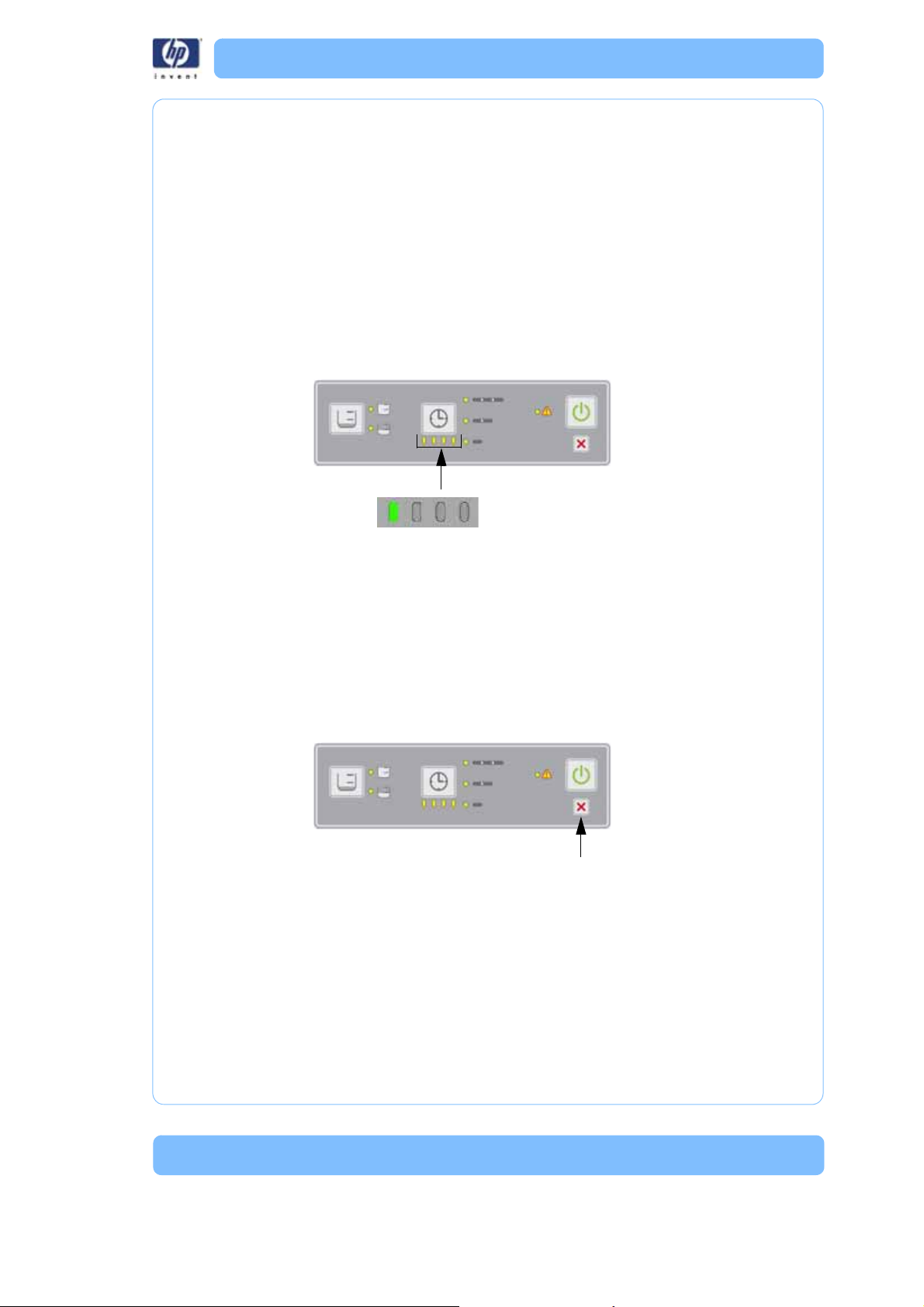
clean water for a final rinse and drain cycle. When the cleaning cycle completes, the left-hand progress LED will turn from yellow to green and the lid
unlocks.
14
Page 15
Remove the models
Cycle
complete
Let the solution drain off of the models for a few minutes then remove the
models, wash off any remaining solution and dry with a clean cloth or paper
towel.
Other informati on
Progress LEDs
When the cleaning cycle is started, all the progress LEDs are illuminated in
yellow. Each progress LED from right to left will turn off as the cycle time progresses. When the cleaning cycle is complete, the left-hand progress LED will
turn from yellow to green.
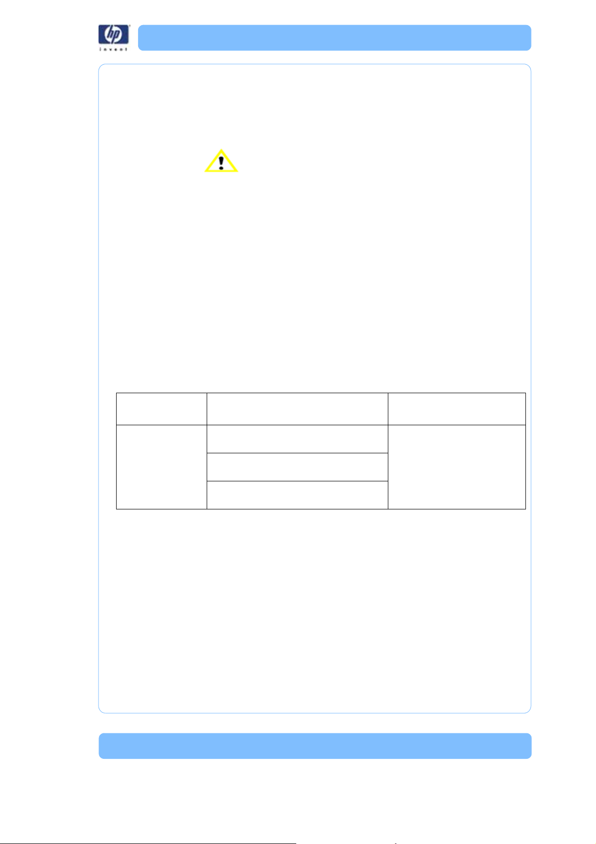
Canceling the cleaning cycle
To cancel the cleaning cycle at anytime, press the cancel button on the control panel. The system will stop and drain the cleaning tank. Before the system completely turns off, the cleaning tank may refill with water for a final
rinse (depending on where the system is in the cleaning cycle) and then
drains again. After the cleaning tank has drained, the lid unlocks so the
model basket can be removed. The drained solution cannot be reused. Models may not be fully cleaned if you cancel the operation.
15
Page 16

Process error LED
A flashing yellow process error LED indicates a warning. See “Troubleshoot-
ing” on page 19 for details.
A red process error LED indicates that the system is experiencing a system
error. See “Troubleshooting” on page 19 for details.
Turning the system off
Once the cleaning cycle is complete and the models have been removed,
the system should be turned off by toggling the power switch on the back
panel to the OFF position. If the system is not going to be used for an
extended period of time, remove all models from the model basket, make
sure the system is completely dry, and the power cord is disconnected from
the power cord receptacle.
16
Page 17

Maintenance
Inspecting and cleaning the strainer
The strainer at the bottom of the cleaning tank should be cleaned before
every use of the system to maintain optimal system performance. Remove the
strainer from the cleaning tank and rinse under water until the strainer is
clean. Place the strainer back in the cleaning tank after cleaning.
Cleaning
The system should be cleaned once a month or sooner as needed. Clean the
exterior and the interior of the cleaning tank with mild soap and water using
a sponge or cloth only. Hard to remove residue can be cleaned with isopropyl alcohol. Never immerse the system or use a spray nozzle or hose to
clean it. Any liquid in the electronics area behind the back panel of the system may damage the system and void the warranty.
Model bag
The model bag should be replaced after 40 cycles. Replace the bag if the
elastic cord starts to droop or the bag shows signs of wear.
17
Page 18

18
Page 19
Troubleshooting
In the presence of unusual electromagnet phenomena, such as strong electromagnetic fields or severe electrical disturbances, the system might behave
strangely, or even stop working. In this case, turn off the system, wait until the
electromagnetic environment has returned to normal and then turn it on
again.
The HP Designjet 3D Removal System has been designed to allow the end
user to resolve most operating problems. When a problem is encountered,
read through this troubleshooting section for possible solutions.
Troubleshooting
Non-Coded Error Conditions
Table 3: Non-Coded Error Conditions
Problem Recommendation
No power Verify that the power cord is securely
plugged in.
Verify that the power switch is in the
ON position.
Verify that AC power is present at the
power outlet.
Replacement Parts
* Part most likely to resolve issue
** Part less likely to resolve issue
* Main controller board
** Line filter
** Thermostat
19
Page 20
Problem Recommendation
Water has not
fully drained from
the cleaning tank
assembly
Verify that the strainer and cleaning
tank drain are not clogged.
Verify that the drain hose is not
clogged.
Verify that there are no kinks in the
drain hoses.
Make sure the system is at least 20 cm
(8 in.) above the drain hose discharge.
Make sure that no section of the drain
hose is higher than the system
discharge.
Verify that the power cord is securely
plugged in.
Verify that the power switch is in the
ON position.
Verify that AC power is present at the
power outlet.
Models not clean Make sure all the contents of the speci-
fied number of cleaning agent bag(s) is
used.
Make sure the correct cleaning tank
assembly level is selected.
Make sure the correct cycle length is
selected.
Repeat the cleaning cycle.
Make sure the model basket is used to
submerge models in the cleaning solution and the correct system lid position
is selected.
Cleaning tank assembly not heating. Note: Verify that the tank has
The system is
leaking
Yellow flashing
process error LED
Verify that the inlet and drain hose
connections are tight.
Open and close the system lid and then
make sure the lid is fully closed.
If recovering from a power loss, press
the cancel button.
Replacement Parts
* Part most likely to resolve issue
** Part less likely to resolve issue
* Agitation drive belt
** Induction motor
** Agitation assembly
** Cleaning tank assembly
failed to heat before
replacing the cleaning tank
assembly, by touching the
tank during unit operation.
*System lid
** System lid sensor
** Cleaning tank assembly
20
Page 21
Error Detection
Error Type
4
2
1
Value
Error Code
Value
8
4
2
1
Error Type
Each error type LED carries a weight value (4, 2, or 1). To obtain the error
type number, add up the weight value associated with the illuminated LED.
For example; if the top LED (4) and the bottom LED (1) are both illuminated,
the value equals 5 (4+1=5).
Figure 4: Error Type
21
Page 22
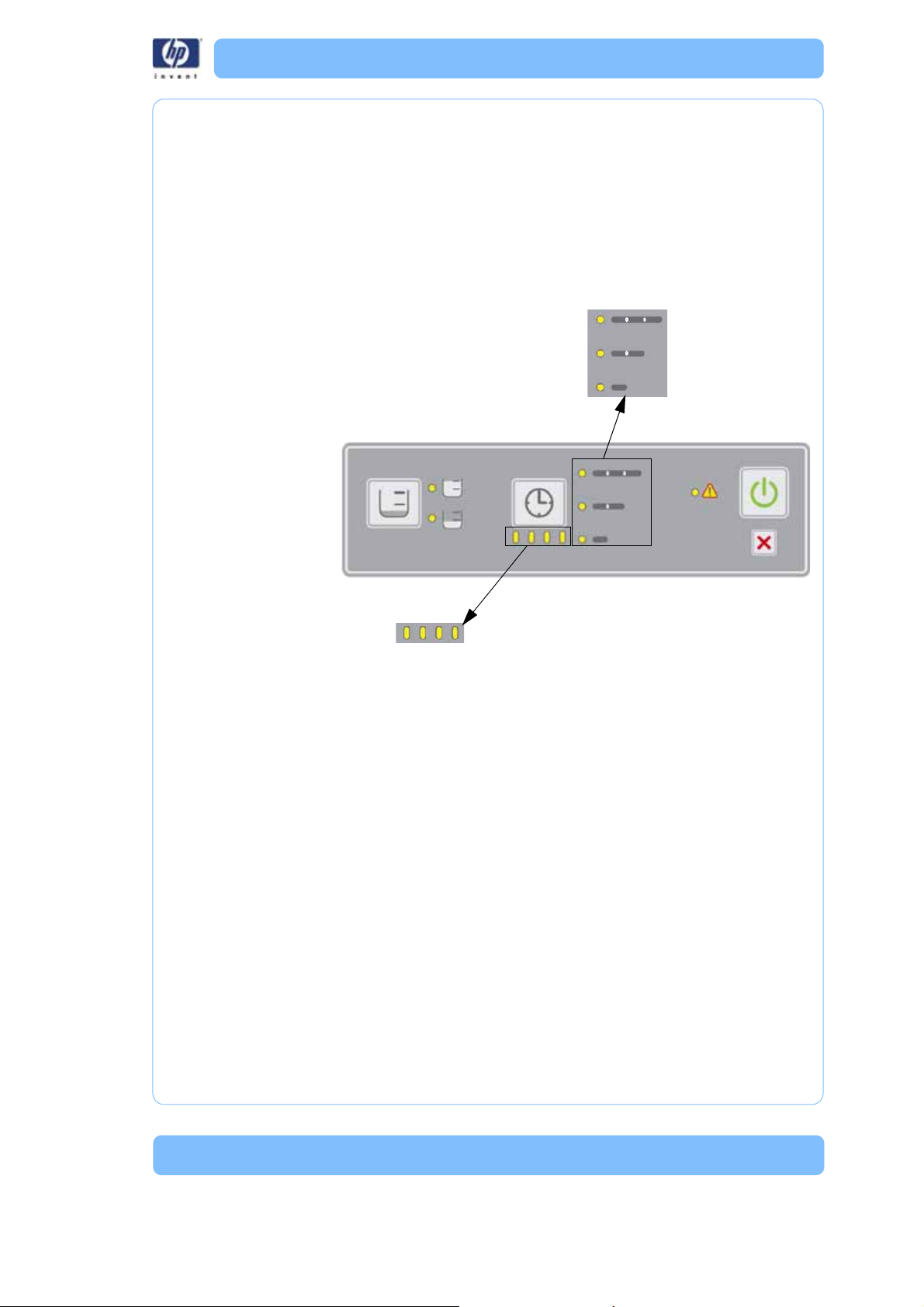
Error Code
Each error code LED carries a weight value (8, 4, 2, or 1). To obtain the
error code number, add up the weight value associated with the illuminated
LED. For example; if the right LED (1) and the third from the right LED (4) are
both illuminated, the value equals 5 (1+4=5).
Note: To obtain error codes, see “Entering Diagnostic
Mode” on page 25 for details.
Table 4: Error Code Chart
Error
Type -Code Description
Replacement Parts
* Part most likely to resolve issue
** Part less likely to resolve issue
1-1 Failed or open thermometer * Thermometer board
** Main controller board
1-8 Set point temperature not reached * Cleaning Tank Assembly
* Main controller board
** Thermometer board
** User interface board
2-1 Ambient temperature error * Thermometer board
** User interface board
** Main controller board
2-2 Wait for high temperature failed * Cleaning Tank Assembly
* Main controller board
** Thermometer board
** User interface board
2-3 Wait for low temperature failed * Thermometer board
** Main controller board
2-4 Wait for the system lid to close failed
1. Check to see if the system lid is closed
2. Check to see if magnet is present in
system lid
CRU:
*System lid
FRU:
* Lid switch assembly
** User interface board
2-5 User interface to main controller
communication error
* User interface board
* Main controller board
2-6 Thermometer communication error * Thermometer board
* User interface board
2-7 Float level sensor assembly not empty
1. Check for drain hose blocked or
* Float level sensor assembly
** Cleaning tank assembly
mis-routed
2. Check to see if drain screen is clean
3-1 System lid open while washing
Check if magnet is secure in system lid
* System lid lock assembly
** System lid switch assembly
** User interface board
** Main controller board
22
Page 23
Error
Type -Code Description
3-2 System lid open while rinsing
Check if magnet is secure in system lid
Replacement Parts
* Part most likely to resolve issue
** Part less likely to resolve issue
* System lid lock assembly
** System switch assembly
** User interface board
** Main controller board
3-3 Power module fault detected * Main controller board
3-4 User interface to main controller
communication error
* User interface board
* Main control board
3-10 Invalid float level sensor assembly state * Float level sensor assembly
** Main controller board
4-1 Invalid float level sensor assembly state * Float level sensor assembly
** Main controller board
4-2 Timeout waiting for low water level
1. Check for water available at inlet
2. Check water pressure at inlet
* Cleaning tank assembly
** Inlet hose
** Main controller board
** Float level sensor assembly
4-3 Timeout waiting for mid water level
1. Check for water available at inlet
2. Check water pressure at inlet
* Cleaning tank assembly
** Float level sensor assembly
** Main controller board
4-4 Unexpected transition to overfill condition * Float level sensor assembly
** Cleaning tank assembly
** Main controller board
4-5 Timeout waiting for full water level
1. Check for water available at inlet
2. Check water pressure at inlet
4-6 Float level sensor assembly error - empty
switch stuck closed
4-7 Timeout waiting for full water level
1. Check for water available at inlet
2. Check water pressure at inlet
4-8 Overfill: Float level sensor assembly error -
mid switch stuck open
4-9 Float level sensor assembly error - mid
switch stuck open
4-10 Float level sensor assembly error - empty
switch stuck closed
* Float level sensor assembly
* Cleaning tank assembly
** Main controller board
* Float level sensor assembly
** Main controller board
* Float level sensor assembly
* Cleaning tank assembly
** Main controller board
* Float level sensor assembly
** Main controller board
* Float level sensor assembly
** Main controller board
* Float level sensor assembly
** Main controller board
4-11 Not empty at start of fill * Float level sensor assembly
** Main controller board
4-12 Float level sensor assembly error (full before
mid)
* Float level sensor assembly
** Main controller board
4-13 Not at target level at the end of fill * Float level sensor assembly
** Main controller board
5-1 Invalid float level sensor assembly state * Float level sensor assembly
** Main controller board
23
Page 24
Error
Type -Code Description
Replacement Parts
* Part most likely to resolve issue
** Part less likely to resolve issue
5-2 Unexpected loss of fluid * Cleaning tank assembly
** Float level board
** Main controller board
5-3 Overfill * Cleaning tank assembly
** Float level board
** Main controller board
5-4 Unexpected loss of fluid and invalid sensor
transition
* Float level sensor assembly
** Main controller board
** Cleaning tank assembly
6-1 Invalid float level sensor assembly state * Float level sensor assembly
** Main controller board
6-2 Timeout waiting for empty
1. Check for drain hose blocked or
* Float level sensor assembly
* Cleaning tank assembly
mis-routed
2. Check drain screen clean
6-3 Unexpected addition of fluid * Cleaning tank assembly
** Float level sensor assembly
** Main controller board
24
Page 25
Diagnostic and Test Specifications
Press Together
Functional Description
Overview
The diagnostic test feature is intended to allow the support engineer to confirm correct operation of a majority of the system’s hardware. Diagnostic testing does not require water be connected to the cleaning tank assembly for
the test sequence to complete successfully. The support engineer will be
required to verify certain hardware is operating properly where the cleaning
tank assembly itself is not capable of detecting it automatically.
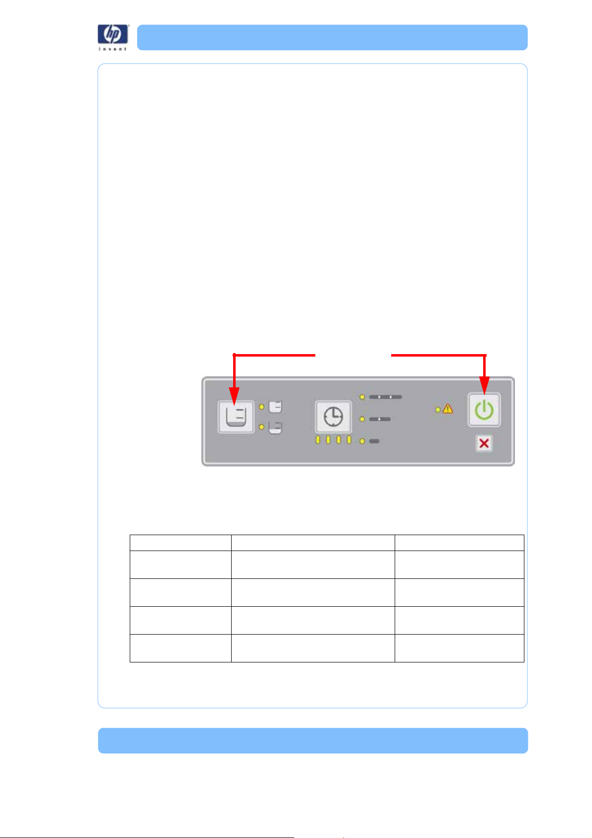
Entering Diagnostic Mode
Diagnostic mode can only be entered when the system is initially powered
off. To enter diagnostic mode, the support engineer must simultaneously hold
down only the ‘start’ and ‘load select’ buttons (farthest apart) when power is
turned on. The system is now in diagnostic mode (indicated by both 'cycle
load' LEDs being ON simultaneously and all ‘cycle length’ and ‘progress status’ LEDs OFF, neither of which should ever occur during normal operating
mode). Normal operation cannot be resumed until this mode is exited. Note
that the input buttons have different functions when in diagnostic mode.
Input functions in Diagnostic Mode
The affect of pressing the interface panel buttons changes when diagnostic
mode is active.
Button Normal mode (for reference only) Diagnostic model
Cycle ‘Load Select’ Rotate though water level options
(FullHalfFull...)
Cycle ‘Length Select’ Rotate though cycle length options
(Long Med Short Long...)
‘Start’ Begin selected cleaning operation Run all diagnostic subtests
‘Cancel’ Abort any operation in progress Exit diagnostic mode(abort
Select subtest (sequential
Run selected subtest
(run remaining subtests)
current subtest)
25
Page 26

Exiting Diagnostic Mode
As long as no errors have been detected, diagnostic mode can be exited
simply by pressing the ‘cancel’ button. If a test sequence is in progress when
the ‘cancel’ button is pressed, the current subtest sequence is aborted, but
the system remains in diagnostic mode. Pressing ‘cancel’ a second time
would then exit diagnostic mode. LEDs should return to their default state for
normal operating mode. Diagnostic mode can also be exited by powering
the system off and on again (without holding down any input buttons).
Initiating the Diagnostic Sequence
The diagnostic subtests can be initiated in one of two ways: 1) “Run all”: run
all subtests with a single button press (with only a short delay between each
subtest), or 2) “Interactive mode”: run one subtest at a time, allowing the
user control over individual subtests. All ‘cycle length’, ‘progress status’, and
‘warning’ LEDs are OFF when diagnostics mode is ready to initiate subtesting.
Run all (entire sequence, no pausing)
To initiate the entire diagnostic test sequence, simply press the ‘start’ button
while in diagnostic mode. This starts a predetermined sequence of subtests
that exercise the system’s hardware. The entire test sequence runs until completion, an error has been detected, or the ‘cancel’ button is pressed. Pressing the ‘load select’ or ‘length select’ button has no affect once the ‘start’
button has initiated the sequence. Note that only a short delay occurs
between subtests; no other input is required to complete the sequence. It
may be helpful to note that diagnostics are best run with the system lid open.
Interactive mode (select subtest to run)
This mode allows individual tests to be selected and executed. To select a
particular test use the ‘load select’ button. Pressing this button selects the next
subtest which is displayed on the ‘cycle length’, ‘progress status’, and the
‘warning’ LEDs. Once the desired subtest is selected the ‘length select’ button
is used to execute that subtest. Pressing the ‘start’ button runs the currently
selected subtest as well as all the remaining subtests from that point on stopping at the final subtest (not looping back to run the first subtest). After successful completion of any subtest, another subtest can be selected using the
‘load select’ button or that same subtest can be run again by pressing the
‘length select’ button. When in the interactive mode, the operator must wait
30 seconds after powering on the system before running the heater subtest.
26
Page 27

Test Sequence
The test sequence has been designed to exercise the hardware one component at a time. Wherever possible, the system automatically detects proper
component operation. Where the system cannot detect component operation, the support engineer is required to confirm component operation (visually or audibly). The test sequence is described below along with a brief
description of each subtest. The sequence runs each subtest in order, unless
an error is detected, in which case the system jumps to the reporting phase
at the end of the test sequence, which displays the code for that error. The
‘cycle length’ and ‘progress status’ LEDs are used to indicate progress
through the test sequence. They should turn on one at a time, from top to bot-
tom, left to right, one for each subtest.
Subtest #
1 LEDs Visual Turn all LEDs ON, then OFF and repeat
2Electronics
Subtest
Name
self-test
Error
Detection Subtest Summary Status Display
once more. Return LEDs to their initial state.
This will display between every test (see
below)
Automatic Perform at any power-up, not just diagnostic
mode. The ‘warning’ LED is ON after
power-up if this subtest ever fails.
All LEDs blink
Topmost ’cycle
length’ LED
(long) ON and
’warning’ LED
is ON.
3 Inlet Valve Audible Open and close valve multiple times. 2 ‘cycle length’
LEDs (long +
medium) ON
and ‘warning’
LED is ON.
4Drain
Valve
Audible Open and close valve multiple times. All 3 ‘cycle
length’ LEDs
ON and ‘warning’ LED is
ON.
27
Page 28

Subtest #
5Motor/
6 Float Level
7 Door Lock Visual The system lid can be either open or shut for
8 Door
Subtest
Name
Propeller
Sensor
Assemblies
Switch
Error
Detection Subtest Summary Status Display
Visual Enable motor (propeller should rotate), then
disable motor.
Visual Verify all float level sensor assemblies can
change state.
this subtest. Door lock is activated 4 times.
Automatic Blink ‘warning’ LED until the support engi-
neer opens and closes the system lid to verify both switch states.
All 3 ‘cycle
length’ and
rightmost
‘progress status’ LEDs ON.
‘Warning’ LED
is ON.
All 3 ‘cycle
length’ and
right 2 ‘progress status’
LEDs ON.
‘Warning’ LED
is ON.
All 3 ‘cycle
length’ and
right 3 ‘progress status’
LEDs ON.
‘Warning’ LED
is ON.
All 3 ‘cycle
length’ and all
4 ‘progress status’ LEDs ON.
‘Warning’ LED
is blinking.
9 Heater Automatic Enable heater until test temperature is
reached (or timeout occurs), then disable
heater.
Sequence Reporting
While the ‘cycle load’ LEDs indicate whether the system is in normal or diagnostic mode, the ‘cycle length’, ‘progress status’, and ‘warning’ LEDs (all yellow) indicate diagnostic status. Reporting is very similar for the “entire
sequence” and “interactive” modes, but subtest completion and error status
are handled differently. For either mode, while a subtest is in progress, the
‘cycle length’, ‘progress status’, and ‘warning’ LEDs indicate which subtest is
active.
All 3 ‘cycle
length’, all 4
‘progress status’, and ‘warning’ LEDs ON
28
Page 29

Run all
Once the test sequence is complete, the ‘cycle complete’ LED turns ON. If no
errors were detected, then all ‘cycle length’, ‘progress status’, and ‘warning’
LEDs are OFF, as is the ‘error’ LED. If an error was detected, then the ‘cycle
length’, ‘progress status’, and ‘warning’ LEDs display an error code. The
‘cycle complete’ LED is OFF while the ‘error’ LED blinks.
Interactive mode
After each subtest completes, the ‘cycle length’, ‘progress status’, and ‘warning’ LEDs momentarily turn OFF while the ‘cycle complete’ LED turns ON.
Note that the ‘cycle complete’ LED is green, but is co-located with the left
most ‘progress status’ LED (yellow). The ‘cycle length’, ‘progress status’, and
‘warning’ LEDs continue to indicate the subtest that is selected; they do not
update unless the ‘load select’ (or ‘start’) button is pressed. After the last subtest, pressing ‘load select’ returns the ‘cycle length’, ‘progress status’, and
‘warning’ LEDs to all OFF.
If a failure was detected in interactive mode, then the ‘error’ LED blinks and
the ‘cycle complete’ LED is OFF while the ‘cycle length’ and ‘progress status’
LEDs display an error code. Note that the ‘error’ LED is red, but is co-located
with the ‘warning’ LED (yellow).
Subtest details
LED subtest
Two of the LED locations are bi-color LEDs. These two are easiest to verify if
only one of each pair of LEDs within the package is turned on at a time during testing. The LED test sequence is as follows: first, turn on all yellow LEDs
(‘cycle length’, ‘progress status’, and ‘warning’) ON for ~2 seconds, turn
those OFF while simultaneously turning the green and red LEDs (‘cycle complete’ and ‘error’) ON for ~2 seconds, then all LEDs OFF for ~2 seconds.
Repeat that ON/OFF cycle once more. Return LEDs to proper state for next
subtest (both ‘cycle load’ LEDs ON, etc.).
This should allow support engineers sufficient time to verify that all LEDs can
turn both ON and OFF.
Electronics Selftest
This subtest is performed at any power-up to normal mode as well as during
the diagnostic test sequence. This subtest should perform an internal check of
any and all possible electronic circuits than can be verified automatically.
Inlet Valve subtest
This subtest opens (default state is closed) and then closes the water inlet
valve at a 2 Hz. rate for a total of 5 cycles. This should allow support engineers an opportunity to hear the valve functioning. The valve must be left in
the default state at the end of the subtest. If the system is connected to a
water source, some water will enter the cleaning tank assembly during this
subtest.
29
Page 30

Drain Valve subtest
This subtest opens (default state is closed) and then closes the drain valve at
a 2 Hz. rate for a total of 5 cycles. This should allow support engineers an
opportunity to hear the valve functioning. The valve must be left in the default
state at the end of the subtest.
Motor/Propeller subtest
This subtest enables the agitation motor for a total of approximately 5 seconds, and then disables the motor. The support engineer should be able to
see the propeller rotating during this time.
Float Level Sensor Assemblies subtest
Since there is currently no manual or automatic way of activating the float
level sensor assemblies, this subtest simply checks that the sensors are in
their default state for an empty cleaning tank assembly.
System Lid Lock subtest
This subtest enables (default state is disabled) and then disables the system
lid lock at a 2 Hz. rate for a total of 5 cycles. This should allow support engineers an opportunity to both see (if the system lid is open) and hear the lock
functioning. The lock must be left disabled at the end of this subtest.
System Lid Switch subtest
This subtest necessarily involves support engineer interaction. The support
engineer must open and close the system lid so that the system can verify
that the system lid switch assembly can reach both states. The support engineer must do this within a specified time limit (10 seconds) or the test fails.
Once both states have been verified, the subtest is complete. In order to help
prompt the support engineer to move the system lid, the ‘warning’ LED
should be blinked at a 2 Hz. rate for the duration of this subtest.
Heater subtest
This subtest starts by verifying that the cleaning tank assembly temperature is
within normal operating limits (T
cleaning tank assembly heater (at ~10% duty cycle) until either the temperature rises T
occurs – whichever comes first. If the temperature limit is reached first, then
the heater is disabled. It is an error if the time limit expires before the temperature limit is reached. The heater should be immediately disabled in case of
an error. During this subtest, the support engineer is allowed to keep the system lid open in order to touch the inside of the sink for manual verification.
Therefore, the subtest temperature limit (T
There is no delay to wait for the system to cool back down after this subtest,
so repeated execution of this subtest will eventually cause a failure due to the
starting temperature being above T
run within 30 seconds of powering on the system.
subtest –limit
above the subtest’s starting temperature or a time-out
env-min
env-max
°C to T
subtest-limit
°C. The heater subtest will fail if
°C). If so, it enables the
env-max
) should be kept < 50°C.
30
Page 31

Service Procedures
Maintenance Preparation............................................................. page 32
Cabinet Components.................................................................... page 34
System Lid .................................................................................... page 34
Lower Housing Assembly................................................................ page 36
Upper Housing Assembly ............................................................... page 38
Hardware Components ................................................................ page 39
Back Panel ................................................................................... page 39
Line Filter...................................................................................... page 44
Thermostat.................................................................................... page 45
Thermometer Board ....................................................................... page 47
User Interface Board...................................................................... page 49
Power Entry Module ...................................................................... page 52
Main Control Board....................................................................... page 54
Cleaning Tank Assembly ................................................................ page 60
Agitation Assembly........................................................................ page 65
Drive Belt ..................................................................................... page 68
Induction Motor Assembly .............................................................. page 70
Float Level Sensor Assembly ........................................................... page 72
Lid Switch Assembly ...................................................................... page 74
Lid Lock Assembly ......................................................................... page 76
31
Page 32

Maintenanc e Preparati on
Read these warnings before performing service on the HP
Designjet 3D Remove System!
WARNING: Make sure the power is disconnected when
performing any of the disassembly or
assembly instructions in this section. Failure
to do so can cause severe personal injury or
damage to the electronics.
WARNING: Servicing instruc tions outlined in this section
are intended for use by qualified personnel
only. Failure to follow these guidelines can
cause severe injury.
WARNING: The Power Switch located on the rear of the
HP Designjet 3D Removal System MUST be
off before service is performed on the
system. It is recommended that the AC power
cord be disconnected before performing
maintenance outlined in this section.
NOTE: All references within this procedure to ‘Left’ or
‘Right’ are made assuming that the system is being
viewed from the ‘Front’ of the system.
NOTE: Before disassembling, make sure all liquid is
removed from the system to prevent trapped liquid from
dripping on the system electronics.
32
Page 33

Required Tool List
1. #1 standard screwdriver
2. #2 standard screwdriver
3. #1 phillips screwdriver
4. #2 phillips screwdriver
5. Pliers
6. Small wire cutters
7. Gr o u n d i n g s t r a p
8. 11/32” box wrench (PN 208853-0001)
9. Box wren ches
Prerequisite procedures
1. Cancel any pending jobs and wait for the system to drain. If the
system is inoperable, see “Inoperable system” on page 33.
2. After the system has drained toggle the On/Off switch at the
back of the system to Off.
3. Remove the AC power cord from the system.
4. Remove the inlet hose and the drain hose from the system.
5. Open the lid and make sure there is no liquid in the cleaning
tank. Drain any liquid from the system making sure that all
trapped liquid is removed from the cleaning tank.
NOTE: Before disassembling, make sure all liquid is
removed from the system to prevent trapped liquid from
dripping on the system electronics.
Inoperable system
If the system lid is in the locked position and cannot be opened, do the
following:
1. Using a #1 standard screwdriver, place the blade of the
screwdriver on the solenoid latch and then force the latch back
into the upper housing. See Figure 10.
2. After the solenoid latch has been moved back into the upper
housing, the lid will be free to open.
Figure 10: Door lock solenoid latch
3. After the lid has been opened, drain any liquid from the system
making sure that all trapped liquid is removed from the cleaning
tank.
33
Page 34

Center hinge pin
Cabinet Components
System Lid Removing th e system li d
1. Open the system lid and then move the lid beyond its natural
stopping point. Continue to move the lid until the lid snaps off
the housing hinges. See Figure 11.
2. Set the lid aside.
Figure 11: System Lid
Installing the system lid
1. Make sure that both lid hinge pins are centered in the hinges.
See Figure 12.
Figure 12: Center hinge pins
2. Position the lid so the lid hinges and the housing hinges line up.
See Figure 13.
34
Page 35

Figure 13: Attaching the lid
Snap lid hinges
onto housing hinges
3. Firmly press the lid hinges onto the housing hinges so the hinges
snap together. A sharp blow with the heel of your hand is sufficient to snap the hinges into place. See Figure 14.
Figure 14: Snapping the lid in place
4. Close the lid.
35
Page 36

Remove 5
screws
Remove 4 screws
Lower Housing Assembly
Required Tools
•#2 phillips screwdriver
Hardware
•10-32 x 1⁄2” phillips screw (x5)
Removing the lower housing assembly
NOTE: Before disassembling, make sure all liquid is
removed from the system to prevent trapped liquid from
dripping on the system electronics.
1. Using a #2 phillips screwdriver, remove the 5 screws that attach
the lower housing to back panel as shown in Figure 15.
Figure 15: Lower Housing screw locations
2. Remove the system lid so it won’t get in the way when servicing
the system. See “Removing the system lid” on page 34.
3. Flip the system upside down to gain access to the bottom of the
system.
4. Using a magnetized #2 phillips screwdriver, remove 4 screws
from the left side and right side of the lower housing. See Figure
16 .
Figure 16: Lower Housing screw locations
5. Lift up the lower housing and set the housing aside.
36
Page 37

Installing the lower housing assembly
NOTE: Prior to reassembling the system, check that
there is no liquid on the system electronics.
1. Place the lower housing in position and attach using 4 screws.
2. Flip the system right-side up.
3. Using a #2 phillips screwdriver, attach 5 screws to the back of
the housing. See Figure 15.
4. Attach the lid to the system. See “Installing the system lid” on
page 34.
37
Page 38

Upper Housing Assembly
Removing the upper housing assembly
1. Remove the back panel. See “Removing the back panel” on
page 39.
2. Remove the user interface board. See “Removing the user inter-
face board” on page 49.
3. Remove the cleaning tank assembly. See “Removing the clean-
ing tank assembly” on page 60.
4. Remove the agitation assembly. See “Removing the agitation
assembly” on page 65.
Figure 17: Upper housing assembly
Installing the upper housing assembly
1. Install the agitation assembly. See “Installing the agitation
assembly” on page 67.
2. Install the cleaning tank assembly. See “Installing the cleaning
tank assembly” on page 61.
3. Install the user interface board. See “Installing the user interface
board” on page 51.
4. Install the back panel. See “Installing the back panel” on
page 42.
38
Page 39

Hardware Co mponents
Remove 2
mounting screws
Remove 2
mounting screws
Back Panel
Required Tools
• #2 phillips screwdriver
•Grounding strap
Hardware
• 8-32 x 3/8” phillips screw (x3)
• 4-0.7 x 10 mm screw (x4)
Removing the back panel
1. Remove the lower housing. See “Removing the lower housing
assembly” on page 36.
2. Using a #2 screwdriver, remove 2 mounting screws that attach
the wastewater drain components to the back panel. See Figure
18 .
3. Using a #2 screwdriver, remove 2 mounting screws that attach
the water inlet components to the back panel.
Figure 18: Back panel screw location
39
Page 40

4. Using a #2 phillips screwdriver, remove 3 locking screws that
Remove 3
locking screws
attach the back panel to the upper housing See Figure 19.
Figure 19: Back panel screw locations
5. Tilt the back panel to gain access the connectors. Be careful not
to put stress on any wire cables.
6. Disconnect the following cable connectors from the main control
board: (see Figure 20)
• P10 Power Cable (PN 208700)
• P8 Motor Power (PN 208709)
•P7 Inlet Valve (PN 208701)
• P6 Drain Valve (PN 208702)
• P1A Heater (PN 208723) (black wire)
• P1B Heater (PN 208723) (white wire)
• P5 Data Cable (PN 208726)
• P4 Level Sensor (PN 208725)
7. Remove 1 grounding screw and remove 2 green grounding
wires. See Figure 20.
40
Page 41

Figure 20: Main board connector locations
P8
P7
P6
P1A
P1B
P5
P4
P10
Grounding
screw
AC GND
EMI P
EMI N
8. Disconnect 1 ground wire from the power entry module (AC
GND). See Figure 21.
9. Disconnect 2 wires from the line filter. (EMI P and EMI N).
10. Remove the back panel from the system.
Figure 21: Main control board connections
41
Page 42

Installing the back panel
Remove 3
locking screws
1. Place the back panel in position.
2. Using a #2 phillips screwdriver, attach 2 green grounding wires
using 1 grounding screw. See Figure 20.
3. Connect the following cables to the main control board: (see
Figure 20)
• P10 Power Cable (PN 208700)
• P8 Motor Power (PN 208709)
•P7 Inlet Valve (PN 208701)
• P6 Drain Valve (PN 208702)
• P1A Heater (PN 208723) (black wire)
• P1B Heater (PN 208723) (white wire)
• P5 Data Cable (PN 208726)
• P4 Level Sensor (PN 208725)
4. Connect 1 ground wire to the power entry module (AC GND).
See Figure 21.
5. Connect 2 wires to the line filter. (EMI P and EMI N).
6. Using a #2 phillips screwdriver, attach the back panel to the
upper housing using 3 screws.
Figure 22: Back panel screw locations
42
Page 43

7. Using a #2 screwdriver, attach wastewater drain components to
Remove 2
mounting screws
Remove 2
mounting screws
the back panel using 2 screws. See Figure 23.
8. Using a #2 screwdriver, attach the water inlet components to
the back panel using 2 screws. See Figure 23
Figure 23: Back panel screw location
9. Install the lower housing. See “Installing the lower housing
assembly” on page 37.
43
Page 44

Line Filter
Remove 2 mounting
screws and 2 star
EMI P
EMI N
AC L
AC N
washers
Required Tools
• #2 phillips screwdriver
Hardware
• 8-32 x 1/4” phillips screw (x2)
Removing the line filter
1. Remove the lower housing. See “Removing the lower housing
assembly” on page 36.
2. Disconnect 2 input wires from the line filter. See Figure 24.
3. Disconnect 2 output wires from the line filter.
4. Using a #2 phillips screwdriver, remove 2 mounting screws that
attach the line filter to the back panel.
5. Remove the line filter from the back panel.
Figure 24: Line filter
Installing the line filter
1. Place the line filter in position and attach the filter to the back
panel using 2 mounting screws.
2. Attach the AC L and the AC N wires to the input of the line filter.
3. Attach the EMI P and the EMI N wires to output of the line filter.
4. Install the lower housing. See “Installing the lower housing
assembly” on page 37.
44
Page 45

Thermostat
Remove 2
mounting nuts
Hot In
Hot Out
Required Tools
• 11/32” box wrench (PN 208853-0001)
Hardware
• 6-32” nut (x2)
Removing the thermostat
1. Remove the lower housing. See “Removing the lower housing
assembly” on page 36.
2. Disconnect 2 wires from the thermostat. See Figure 25.
3. Using the 11/32” box wrench (PN 208853-0001), remove 2
11/32” mounting nuts that attach the thermostat to the cleaning
tank.
Figure 25: Thermostat nut locatio n
45
Page 46

4. Remove the thermostat and the thermal heat sink pad from the
Thermostat
Heat sink
pad
system. See Figure 26.
Figure 26: Thermostat removal
Installing the thermostat
1. Place the heat sink pad in position on the cleaning tank.
2. Place the thermostat in position over the heat sink pad.
3. Using the 11/32” box wrench (PN 208853-0001), attach the
thermostat to the cleaning tank using 2 11/32” mounting nuts.
Make sure the thermal heat sink pad is between the thermostat
and the cleaning tank and has not shifted.
4. Connect 2 wires on the thermostat. See Figure 25.
5. Install the lower housing. See “Installing the lower housing
assembly” on page 37.
46
Page 47

Thermometer Board
Remove 2
mounting nuts
J20
Required Tools
•5/16” wrench
•Grounding strap
Hardware
• 6-32” nut (x2)
Removing the thermometer board
1. Remove the lower housing. See “Removing the lower housing
assembly” on page 36.
2. Disconnect J20 from the thermometer board. See Figure 27.
3. Using a 5/16” wrench, remove the 2 mounting nuts that secure
the thermometer board to the cleaning tank.
Figure 27: Thermometer board
47
Page 48

4. Remove the thermometer board and the heat sink pad from the
Heat sink
pad
Thermometer
board
Stud spacers
remain in place
cleaning tank. Make sure the stud spacers remain in place. See
Figure 28.
Figure 28: Thermometer board removal
Installing the thermometer
1. Place the heat sink pad between the thermometer board and
the cleaning tank.
2. Using the 5/16” box wrench, attach the thermometer board to
the cleaning tank using 2 5/16” nuts. Make sure the heat sink
pad is positioned properly between the board and the cleaning
tank. Do not over tighten the 5/16” nuts.
3. Connect J20 to the thermometer board. See Figure 27
4. Install the lower housing. See “Installing the lower housing
assembly” on page 37.
48
Page 49

User Interface Board
P37
P33
P32
P31
P34
Required Tools
• #2 phillips screwdriver
• Ground strap
Hardware
• 6-32 3/16” phillips screw (x4)
Removing the user interface board
1. Remove the lower housing. See “Removing the lower housing
assembly” on page 36.
2. Disconnect the following cable connectors (see Figure 32) from
the user interface board:
• P33 Door sensor (PN 208705)
•P32 Door solenoid (PN 208704)
• P31 Thermal sensor (208706-0001)
•P34 Power strip
• P37 Data and power (PN 208726)
Figure 29: Connector locations
49
Page 50

3. To unlock connector bracket on P36, squeeze and pull up on
Pull up on the
data cable
P36
Squeeze and pull up
ends of connector bracket
Remove 3 mounting screws
Remove 1 mounting
screw and 1 grounding
wire
the ends of the connector bracket. See Figure 30.
4. Disconnect the flexible data cable by pulling the cable out of
connector P36. See Figure 30.
Figure 30: Flexible data cable removal
5. Using a #2 phillips screwdriver, remove 3 mounting screws that
attach the user interface board to the board mounting bracket.
See Figure 31.
6. Using a #2 phillips screwdriver, remove 1 mounting screw
along with 1 grounding wire. See Figure 31.
Figure 31: User interface board screw locations
7. Remove the user interface board.
50
Page 51

Installing the user interface board
1. Place the user interface board in position over the standoffs.
2. Using a #2 phillips screwdriver, attach the board to the stand-
offs using 3 mounting screws.
3. Using a #2 phillips screwdriver, attach 1 grounding wire and 1
mounting screw to secure the board to the system.
4. Connect the flexible data cable (P36) to the interface board.
Make sure to securely lock the connector bracket in position by
pushing down on the bracket.
5. Connect the following cable connectors to the interface board:
(see Figure 29)
• P33 Door sensor (PN 208705)
• P32 Door solenoid ( 208704)
• P31 Thermal sensor (208706-0001)
•P34 Power strip
• P37 Data and power (PN 208726)
6. Install the lower housing. See “Installing the lower housing
assembly” on page 37.
51
Page 52

Power Entry Module
Green wire
White wire
Black wire
(L)
(N)
(Ground)
Metal tab
Required Tools
• #2 standard screwdriver
Removing the power entry module
1. Remove the lower housing. See “Removing the lower housing
assembly” on page 36.
2. Disconnect 3 wires from the back of the power entry module.
See Figure 32.
Figure 32: Power Entry Module Wires
3. Using a #2 standard screwdriver, press the metal tabs on the
power entry module in and remove the module from the back
panel. See Figure 33.
Figure 33: Power Entry Module
52
Page 53

Installing the power entry module
1. Press the power entry module into the back panel making sure
the metal tabs lock in place.
2. Attach 3 wires to the back of the power entry module. See Fig-
ure 32 for wiring details.
3. Install the lower housing. See “Installing the system lid” on
page 34.
53
Page 54

Main Control Board
Required Tools
• #2 phillips screwdriver
•Grounding strap
Hardware
• 8-32 x 1-3/8” nylon phillips screw (x3)
• 6-32 x 3/16” phillips screw (x7)
• 8-32 x 3/8” phillips screw (x3)
• 4-0.7 x 10 mm screw (x4)
Removing the main control board
1. Remove the lower housing. See “Removing the lower housing
assembly” on page 36.
2. Using a #2 screwdriver, remove 2 mounting screws that attach
the wastewater drain components to the back panel. See Figure
34.
3. Using a #2 screwdriver, remove 2 mounting screws that attach
the water inlet components to the back panel.
54
Page 55

Figure 34: Back panel screw location
Remove 2
mounting screws
Remove 2
mounting screws
55
Page 56

4. Using a #2 phillips screwdriver, remove 3 locking screws that
Remove 3
locking screws
attach the back panel to the upper housing.
Figure 35: Back panel screw locations
5. Tilt the back panel to gain access the connectors. Be careful not
to put stress on any wire cables.
6. Disconnect the following cable connectors from the main control
board: (see Figure 36)
• P10 Power Cable (PN 208700)
• P8 Motor Power (PN 208709)
•P7 Inlet Valve (PN 208701)
• P6 Drain Valve (PN 208702)
• P1A Heater (PN 208723) (black wire)
• P1B Heater (PN 208723) (white wire)
• P5 Data Cable (PN 208726)
• P4 Level Sensor (PN 208725)
7. Remove 1 grounding screw and remove 2 green grounding
wires. See Figure 36.
56
Page 57

Figure 36: Main board connector locations
P8
P7
P6
P1A
P1B
P5
P4
P10
Grounding
screw
AC GND
EMI P
EMI N
8. Disconnect 1 ground wire from the power entry module (AC
GND). See Figure 37.
9. Disconnect 2 wires from the line filter. (EMI P and EMI N).
Figur e 37: Main control board connections
57
Page 58

Remove 3
nylon screws
Remove 7 mounting screws
Remove 3 wing
nuts and 3 nylon
screws
10. Remove 7 mounting screws that attach the main control board
to the back panel. See Figure 38.
11. Remove 3 nylon screw that attach the main control board to the
back panel.
Figure 38: Main control board mounting screws
12. Remove the main control board from the back panel.
Installing the main control board
1. Remove the 3 shipping wing nuts and 3 nylon screws before
installing the control board.
2. Place the main control board in position and using a #2 phillips
screwdriver, attach but do not tighten 7 mounting screws that
attach the main control board to the back panel.
3. Using a #2 phillips screwdriver, attach but do not tighten 3
nylon mounting screws to secure the main control board to the
back panel.
4. After all 7 screws and the 3 nylon screws are installed, go back
and tighten all the screws.
58
Page 59

5. Using a #2 phillips screwdriver, attach 2 green grounding wires
using 1 grounding screw. See Figure 36.
6. Connect the following cables to the main control board: (see
Figure 36)
• P10 Power Cable (PN 208700)
• P8 Motor Power (PN 208709)
•P7 Inlet Valve (PN 208701)
• P6 Drain Valve (PN 208702)
• P1A Heater (PN 208723) (black wire)
• P1B Heater (PN 208723) (white wire)
• P5 Data Cable (PN 208726)
• P4 Level Sensor (PN 208725)
7. Connect 1 ground wire to the power entry module (AC GND).
See Figure 37.
8. Connect 2 wires to the line filter. (EMI P and EMI N).
9. Install the lower housing. See “Installing the lower housing
assembly” on page 37.
59
Page 60

Cleaning Tank Assembly
Tank holding
clamps (X4)
Required Tools
• #2 phillips screwdriver
•Anti-seize compound
• Tank chassis seal
• Alcohol wipes
Hardware
• 8-32 x 3/8” phillips screw (x12)
Removing the cleaning tank assembly
1. Remove the back panel. See “Removing the back panel” on
page 39.
2. Remove the user interface board. See “Removing the user inter-
face board” on page 49.
3. Using a #2 phillips screwdriver, remove the 4 tank holding
clamps. Each clamp has 3 mounting screws securing each
clamp to the upper housing. See Figure 39.
Figure 39: Cleaning tank clamp removal
4. Disconnect the 2 spade connectors from the drain solenoid. See
Figure 40.
5. Disconnect the 2 spade connectors from the thermostat.
6. Remove 5 screws that attach the cleaning tank to the agitation
assembly and remove the agitation assembly.
60
Page 61

Figure 40: Cleaning tank removal locations
Drain solenoid
spade connectors
Thermostat spade
connectors
Remove 5 mounting screws
Remove and discard
the tank chassis
seal
7. Remove the cleaning tank from the system by slightly twisting
the cleaning tank to clear the agitation assembly.
8. Remove and discard the tank chassis seal from the upper hous-
ing. See Figure 41.
Figure 41: Cleaning tank assembly removal
Installing the cleaning tank assembly
1. Use alcohol wipes to clean any remnants left by the tank chassis
seal.
2. Position the tank chassis gasket over the agitation assembly as
show in Figure 42. Make sure the holes in the tank chassis gasket aligned over the threaded holes on the agitator assembly.
3. Install the cleaning tank on top of the lower housing making
sure to not wrinkle the tank chassis seal.
61
Page 62

Alignment holes (5X)
Figure 42: Agitation assembly tank chassis gasket alignment
4. Using a #2 phillips screwdriver, attach the cleaning tank to the
upper housing using 5 screws. Make sure to use anti-seize compound on the screws before installing.
5. Using a #2 phillips screwdriver, loosely attach 4 tank holding
clamps. Each holding clamp is secured to the upper housing by
3 screws each. The tank holding clamps are all a unique size so
make sure they are in their proper location.
62
Page 63

Tighten 3 screws on this tank clamp last.
Tighten 3 screws on this tank clamp next.
Tighten 3 screws on this tank clamp next.
Tighten 3 screws on this tank clamp first.
6. After all 4 tank clamps are in and their screws are holding the
cleaning tank in position, tighten the 4 tank clamps in the
sequence show in Figure 43.
Figure 43: Cleaning tank tightening sequence
63
Page 64

7. Install the user interface board. See “Installing the user interface
board” on page 51.
8. Install the back panel. See “Installing the back panel” on
page 42.
64
Page 65

Agitation Assembly
Remove
1 screw
Required Tools
• #2 phillips screwdriver
•Anti-seize compound
Hardware
• 8-32 x 3/8” phillips screw (x1)
• #8 lock washer (x1)
Removing the agitation assembly
1. Remove the back panel. See “Removing the back panel” on
page 39.
2. Remove the user interface board. See “Removing the user inter-
face board” on page 49.
3. Remove the cleaning tank assembly. See “Removing the clean-
ing tank assembly” on page 60.
4. Using a #2 phillips screwdriver, remove 1 mounting screw and
1 lock washer that attach the agitation assembly to the upper
housing. See Figure 44.
Figure 44: Agitation assembly removal
5. Lift up and remove the agitation assembly from the upper hous-
ing.
65
Page 66

Tension idler
pulley
Move to
relieve
tension
Remove 1
motor grounding
screw and 1
Remove 4
mounting screws
grounding wire
6. Move the tension idler pulley to relieve tension on the drive belt
and then remove the drive belt. See Figure 45.
Figur e 45: Drive belt replacement
7. Using a #2 screwdriver, remove 1 grounding screw and 1
grounding wire.
8. Using a #2 screwdriver, remove the 4 mounting screws.
Figure 46: Induction motor assembly
n
9. Remove the induction motor from the agitation assembly for
installation on the new agitation assembly.
66
Page 67

Installing the agitation assembly
1. Install the induction motor removed from the old agitation
assembly onto the new agitation assembly.
2. Move the tension idler pulley up and then install the drive belt
as shown in Figure 47.
Figur e 47: Drive belt installation
3. Place the agitation assembly in position on the upper housing.
4. Using a #2 phillips screwdriver, attach 1 screw and 1 lock
washer to secure the agitation assembly to the upper housing.
Make sure to use anti-seize compound on the screw before
installing.
5. Install the cleaning tank assembly. See “Installing the cleaning
tank assembly” on page 61.
6. Install the user interface board. See “Installing the user interface
board” on page 51.
7. Install the lower housing. See “Installing the lower housing
assembly” on page 37.
8. Install the back panel. See “Installing the back panel” on
page 42.
67
Page 68

Tension idler
pulley
Move to
relieve
tension
Drive Belt
Removing the drive belt
1. Remove the back panel. See “Removing the back panel” on
page 39.
2. Remove the user interface board. See “Removing the user inter-
face board” on page 49.
3. Remove the cleaning tank assembly. See “Removing the clean-
ing tank assembly” on page 60.
4. Remove the agitation assembly. See “Removing the agitation
assembly” on page 65.
5. Move the tension idler pulley to relieve tension on the drive belt
and then remove the belt. See Figure 48.
Figure 48: Drive belt replacement
Installing the drive belt
1. Move the tension idler pulley up and then install the drive belt
as shown in Figure 49.
Figure 49: Drive belt installation
68
Page 69

2. Install the agitation assembly. See “Installing the agitation
assembly” on page 67.
3. Install the cleaning tank assembly. See “Installing the cleaning
tank assembly” on page 61.
4. Install the user interface board. See “Installing the user interface
board” on page 51.
5. Install the back panel. See “Installing the back panel” on
page 42.
69
Page 70

Tension idler
pulley
Move to
relieve
tension
Induction Motor Assembly
Required Tools
• #2 phillips screwdriver
Hardware
• #10 lock washer (x4)
• #10 flat washer (x4)
• 10-32 x 3/4” phillips screw (x4)
Removing the induction motor assembly
1. Remove the back panel. See “Removing the back panel” on
page 39.
2. Remove the user interface board. See “Removing the user inter-
face board” on page 49.
3. Remove the cleaning tank assembly. See “Removing the clean-
ing tank assembly” on page 60.
4. Remove the agitation assembly. See “Removing the agitation
assembly” on page 65.
5. Move the tension idler pulley to relieve tension on the drive belt
and then remove the belt. See Figure 50.
Figur e 50: Drive belt replacement
70
Page 71

6. Using a #2 screwdriver, remove 1 grounding screw and 1
Remove 1
motor grounding
screw and 1
Remove 4
mounting screws
grounding wire
grounding wire.
7. Using a #2 screwdriver, remove the 4 mounting screws.
Figure 51: Induction motor assembly
8. Remove the induction motor from the agitation assembly.
Installing the induction motor assembly
n
1. Place the induction motor assembly in position and using a #2
phillips screwdriver, attach 4 screws to secure the motor to the
agitation assembly.
2. Using a #2 phillips screwdriver, attach 1 grounding wire to the
induction motor assembly.
3. Install the drive belt. See “Installing the drive belt” on page 68.
4. Install the agitation assembly. See “Installing the agitation
assembly” on page 67.
5. Install the cleaning tank assembly. See “Installing the cleaning
tank assembly” on page 61.
6. Install the user interface board. See “Installing the user interface
board” on page 51.
7. Install the back panel. See “Installing the back panel” on
page 42.
71
Page 72

Float Level Sensor Assembly
Required Tools
• #2 phillips screwdriver
•Anti-seize compound
Hardware
• #8 lock washer (x2)
• 8-32 x 3/8” phillips screw (x7)
Removing the float level sensor assembly
1. Remove the back panel. See “Removing the back panel” on
page 39.
2. Remove the user interface board. See “Removing the user inter-
face board” on page 49.
3. Remove the cleaning tank assembly. See “Removing the clean-
ing tank assembly” on page 60.
4. Remove the agitation assembly. See “Removing the agitation
assembly” on page 65.
5. Using a #2 phillips screwdriver, remove 5 cable routing clamps.
See Figure 52.
6. Lift the float level sensor assembly out of the agitation assembly.
7. Using a #2 phillips screwdriver, remove the 2 screws that attach
the float level sensor assembly to the agitation assembly.
8. Remove the float level sensor assembly from the agitation
assembly.
72
Page 73

Figure 52: Float level sensor assembly
Remove 5 screws
Remove
2 screws
and 2 lock
washers
Installing the float level sensor assembly
1. Place the float level sensor assembly in the agitation assembly.
2. Using a #2 phillips screwdriver, secure the float level sensor
assembly to the agitation assembly with 2 screws. Make sure to
use anti-seize compound on the screws before installing.
3. Using a #2 phillips screwdriver, secure 5 cable routing clamps
to the agitation assembly standoffs. Make sure to use anti-seize
compound on the screws before installing.
4. Install the agitation assembly. See “Installing the agitation
assembly” on page 67.
5. Install the cleaning tank assembly. See “Installing the cleaning
tank assembly” on page 61.
6. Install the user interface board. See “Installing the user interface
board” on page 51.
7. Install the lower housing. See “Installing the lower housing
assembly” on page 37.
8. Install the back panel. See “Installing the back panel” on
page 42
73
Page 74

Lid Switch Assembly
Remove 1 screw and 1 flat washer
Lid switch
Required Tools
• #2 phillips screwdriver
Hardware
• 0.174 x 0.375 flat washer (x1)
• 8-32 x 5/8” phillips screw (x1)
Removing the lid switch assembly
1. Remove the back panel. See “Removing the back panel” on
page 39.
2. Remove the user interface board. See “Removing the user inter-
face board” on page 49.
3. Remove the cleaning tank assembly. See “Removing the clean-
ing tank assembly” on page 60.
4. Remove the agitation assembly. See “Removing the agitation
assembly” on page 65.
5. Using a #2 phillips screwdriver, remove 1 screw that attaches
the lid switch assembly to the agitation assembly. See Figure
53.
Figure 53: Lid switch assembly
74
Page 75

Installing the lid switch assembly
Wire routing
1. Place the lid switch assembly in position and using a #2 phillips
screws, attach the lid switch assembly to the agitation assembly
2. Route the wiring as shown in Figure 54. Make sure no wiring is
pinched during installation.
Figure 54: Lid lock assembly wire routing
3. Install the agitation assembly. See “Installing the agitation
assembly” on page 67.
4. Install the cleaning tank assembly. See “Installing the cleaning
tank assembly” on page 61.
5. Install the user interface board. See “Installing the user interface
board” on page 51.
6. Install the back panel. See “Installing the back panel” on
page 42.
75
Page 76

Lid Lock Assembly
Remove 3
screws
Required Tools
• #2 phillips screwdriver
Hardware
• 8-32 x 3/8” phillips screw (x3)
• #8 lock washer (x3)
• 0.174 x 0.375 flat washer (x3)
Removing the lid lock assembly
1. Remove the back panel. See “Removing the back panel” on
page 39.
2. Remove the user interface board. See “Removing the user inter-
face board” on page 49.
3. Remove the cleaning tank assembly. See “Removing the clean-
ing tank assembly” on page 60.
4. Remove the agitation assembly. See “Removing the agitation
assembly” on page 65.
5. Using a #2 phillips screwdriver, remove 3 screws that attach the
lid lock assembly to the agitation assembly. See Figure 55
Figure 55: Lid lock assembly removal
6. Remove the lid lock assembly from the agitation assembly.
76
Page 77

Installing the lid lock assembly
Wire routing
1. Using a #2 phillips screwdriver, loosely attach the lid lock
assembly to the agitation assembly.
2. Temporarily place the agitation assembly in position and adjust
the lid lock assembly for smooth operation and with no binding.
Using a #2 phillips screwdriver, tighten 3 screws to secure the
solenoid to the agitation assembly.
3. Route the wiring as shown in Figure 56. Make sure no wiring is
pinched during installation.
Figure 56: Lid lock assembly wire routing
4. Install the agitation assembly. See “Installing the agitation
assembly” on page 67.
5. Install the cleaning tank assembly. See “Installing the cleaning
tank assembly” on page 61.
6. Install the user interface board. See “Installing the user interface
board” on page 51.
7. Install the back panel. See “Installing the back panel” on
page 42.
77
Page 78

78
Page 79

Appendix
Illustrated Parts Breakdown
Cabinet Components.................................................................... page 78
Upper Components...................................................................... page 79
Lower Components ...................................................................... page 80
79
Page 80

1
2
5
4
3
6
7
System Components
Figure 1: System component locations
Item Part Number Description Qty
1 CQ658-67014 Lower Housing Assembly 1
2 CQ658-67015 Upper Housing Assembly 1
3 CQ658-67019 System Lid 1
4 CQ658-67027 Dual Level Part Basket 1
5 CQ658-67026 Filter Sink Drain 1
6 CQ658-67024 Drain Hose (with clamp) 1
7 CQ658-67025 Inlet Hose 1
80
Page 81

Upper Components
1
2
3
4
5
6
Figure 2: Upper components location
Item Part Number Description Qty
1 CQ658-67005 Induction Motor Assembly 1
2 CQ658-67006 Drive Belt 1
3 CQ658-67007 Float Level Sensor Assembly 1
4 CQ658-67008 Lid Switch Assembly 1
5 CQ658-67009 Lid Lock Assembly 1
6 CQ658-67017 Agitation Assembly 1
81
Page 82

3
4
2
7
6
5
Cleaning Tank Assembly Back View
1
Internal Components
Figure 3: Inte rnal components location
Item Part Number Description Qty
1 CQ658-67011 Main Control Board 1
2 CQ658-67030 Line Filter 1
3 CQ658-67012 Thermometer Board 1
4 CQ658-67013 User Interface Board 1
5 CQ658-67017 Cleaning Tank Assembly 1
6 CQ658-67001 Thermostat 1
7 CQ658-67010 Power Entry Module 1
82
 Loading...