

Page 1

HP Designjet 3D Printer
HP Designjet Color 3D Printer
User Guide
Page 2

Legal Notice
The information contained herein is subject
to change without notice.
The only warranties for HP Products and
services are set forth in the express warranty
statement accompanying such products and
services. Nothing herein should be
construed as constituting an additional
warranty. HP shall not be liable for technical
or editorial errors or omissions contained
herein.
© 2011 Hewlett-Packard Development
Company, L.P.
Rev. B
Microsoft
trademarks of Microsoft Corporation.
.
®
and Windows
®
are U.S. registered
Page 3

Table of Contents
1 Introduction.............................................................................................................................. 1
How to use this guide.............................................................................................. 1
Learn More! ........................................................................................................... 1
Safety precautions .................................................................................................. 2
2 Overview ................................................................................................................................. 3
Finding more information ........................................................................................ 9
3 Setup ..................................................................................................................................... 10
Installing software................................................................................................. 10
Networking the printer .......................................................................................... 10
Establishing network communication with the printer ................................................. 11
Installing Firmware on printer ................................................................................. 14
Adding the second HP Designjet 3D Material Bay .................................................... 14
4 Operation .............................................................................................................................. 19
Display panel and keypad ..................................................................................... 19
System firmware overview ..................................................................................... 20
HP Designjet 3D Software Solution overview............................................................ 21
Processing your STL file for printing ......................................................................... 22
Building a part ..................................................................................................... 24
The display panel during build ............................................................................... 25
Chamber Lights .................................................................................................... 25
Pausing a build .................................................................................................... 25
Resuming after pause ............................................................................................ 25
Canceling a build ................................................................................................. 26
Removing a completed part ................................................................................... 26
Removing HP Designjet 3D Support Material............................................................ 27
Emptying the purge bucket..................................................................................... 27
Replacing material for single material bay ............................................................... 28
Replacing material for dual material bays ................................................................ 28
Material bay LEDs................................................................................................. 29
Replacing material spools ...................................................................................... 30
Storing material spools .......................................................................................... 30
Auto power down................................................................................................. 32
Powering off ........................................................................................................ 32
Resuming operations from Standby mode ................................................................ 32
Updating printer firmware:..................................................................................... 32
i
Page 4

5 Maintenance .......................................................................................................................... 34
Startup kit tools........................................................................................................... 34
Preventive Maintenance............................................................................................... 34
Daily................................................................................................................... 34
500 Hour maintenance ............................................................................................... 35
Tip wipe assembly ................................................................................................ 35
Tip shield replacement........................................................................................... 37
Remove debris from the Filament Present switch........................................................ 40
2000 Hour maintenance ............................................................................................. 41
Tip replacement and calibration ............................................................................. 41
Chamber light bar replacement .............................................................................. 47
6 Troubleshooting...................................................................................................................... 48
Troubleshooting................................................................................................... 48
Fault determination codes ...................................................................................... 50
Exporting printer configuration (.cfg) file.................................................................. 50
Cycling power...................................................................................................... 50
Diagnosing loss of extrusion................................................................................... 51
Clogged tip ......................................................................................................... 52
Material Jam ........................................................................................................ 53
Recovering from loss of extrusion ............................................................................ 55
7 Support.................................................................................................................................. 59
Introduction.......................................................................................................... 59
HP Professional Services ........................................................................................ 59
8 Recycling................................................................................................................................ 61
Removing the EEproms from the material guides ....................................................... 62
Removing the desiccant from the material spool........................................................ 62
9 Printer Specifications............................................................................................................... 63
Physical specifications ........................................................................................... 63
Facility specifications ............................................................................................ 63
Power specifications.............................................................................................. 64
Ecological specifications........................................................................................ 64
Environmental specifications................................................................................... 64
Acoustic specifications .......................................................................................... 64
10 Supplemental Information ....................................................................................................... 65
HP Designjet 3D and HP Designjet Color 3D Printer series ......................................... 65
Hewlett Packard Limited Warranty Statement ........................................................... 65
Declaration of conformity....................................................................................... 68
Regulatory and Environmental Information ............................................................... 69
ii
Page 5

Introduction
HP Designjet 3D printer and HP Designjet Color 3D printer are designed with ultimate simplicity
in mind. The printer enables you to build parts quickly and easily, even if you’ve never used a
3D printer before.
The printers build models with HP Designjet 3D ABS Material so parts are strong and durable.
HP Designjet 3D ABS Material also ensures you will be able to drill, tap, sand and paint your
creations. HP Designjet 3D printer and HP Designjet Color 3D printer are an innovative
combination of proprietary hardware, software and material technology.
Welcome to the new dimension of 3D modeling!
How to use this guide
Introduction
This User Guide is laid out in easy to follow sections which cover Set-up, Operation,
Maintenance, and Troubleshooting. Read each section carefully so that you will get the best
performance from your printer.
Throughout this User Guide, text representing Interface Messages that appear on the display
panel are presented in a bold font.
Learn More!
An electronic User Guide is available on the startup DVD. This guide provides information on the
following topics:
• Troubleshooting information
• Important safety notices and regulatory information
• Information about supported printing supplies
• Detailed user instructions
You can also find more information at HP’s support website.
http://www.hp.com/go/3dprinter/knowledgecenter/
1
Page 6
Safety precautions
Introduction
The following precautions ensure the proper use of the printer and prevent the printer from being
damaged. Follow these precautions at all times.
• Use the power supply voltage specified on the nameplate. Avoid overloading the printer’s
electrical outlet with multiple devices.
• Ensure the printer is well-grounded. Failure to ground the printer may result in electrical
shock, fire and susceptibility to electromagnetic interference.
• Before disassembling or repairing the printer yourself, contact your local Service
Representative. See Support section of User Guide.
• Use only the power cord supplied with the printer. Do not damage, cut or repair the power
cord. A damaged power cord has risk of fire and electric shock. Replace a damaged
power cord with an approved power cord.
• Do not allow metal or liquids to touch the internal parts of the printer. Doing so may cause
damage, fire, electric shock or other serious hazards.
• Power off the printer and disconnect the power cord from the power outlet in any of the
following cases:
• If there is smoke or an unusual smell coming from the printer.
• If the printer is making an unusual noise not heard during normal operation.
• A piece of metal or a liquid touches the internal parts of the printer.
• During an electrical (thunder/lightning) storm
• During a power failure
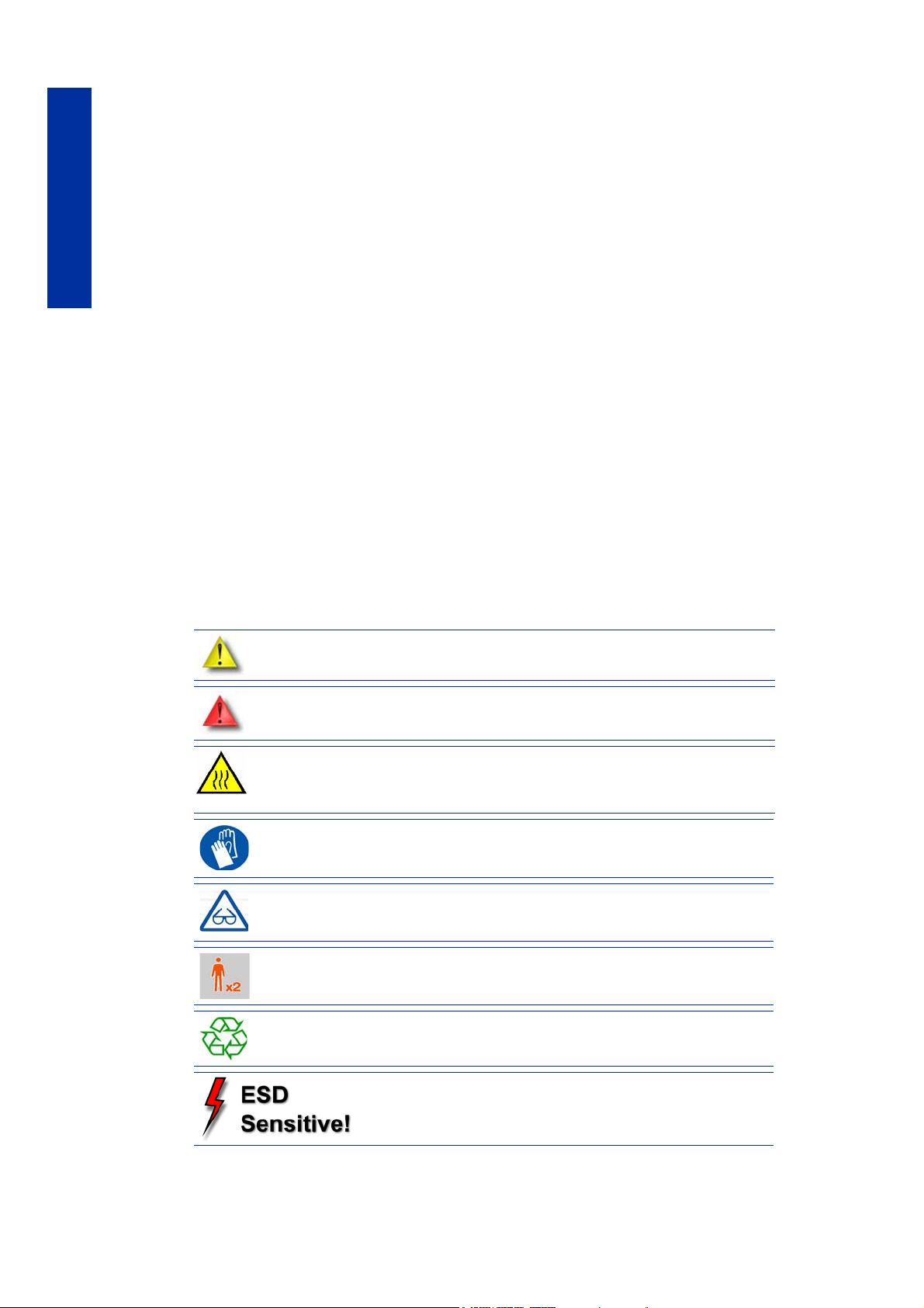
The following classifications are used throughout this guide:
CAUTION: Indicates a potentially hazardous situation which, if not avoided,
may result in minor or moderate injury.
WARNING: Indicates a potentially hazardous situation which, if not avoided,
could result in serious injury.
HOT SURFACE: The hot surface sign indicates the presence of devices with
high temperatures. Always use extra care, and wear safety gloves, when working around heated components
GLOVES: When performing some maintenance procedures, the machine
may be hot and gloves will be required to avoid burns.
SAFETY GLASSES: Wear safety glasses to avoid injury to your eyes.
LIFTING HAZARD: Lift with two or more people to avoid serious injury.
RECYCLE: Use proper recycling techniques for materials and packaging.
ESD: Use standard electrostatic discharge (ESD)
precautions when working on or near electrical
components.
2
Page 7

Overview
HP Designjet 3D Printer and HP Designjet Color 3D Printer build models from CAD STL files. The
printer builds three-dimensional parts by extruding a bead of ABS material through a computercontrolled extrusion head, producing high quality parts that are ready to use immediately after
completion.
HP Designjet 3D Printer and HP Designjet Color 3D Printer consist of two primary components
— the 3D printer and material bay. HP Designjet 3D Software Solution is the preprocessing
software that runs on Windows XP Pro, Windows Vista or Windows 7 platforms.
HP Designjet 3D Printer builds a maximum part size of 8 x 6 x 6 in (203 x 152 x 152 mm). HP
Designjet Color 3D Printer builds a maximum part size of 8 x 8 x 6 in (203 x 203 x 152 mm).
Each material carrier contains 40 cu. in (700 cc) of usable material — enough to build
continuously for about 48 hours without reloading. You can add an optional second material
bay for extended build times.
Overview
3
Page 8
Overview
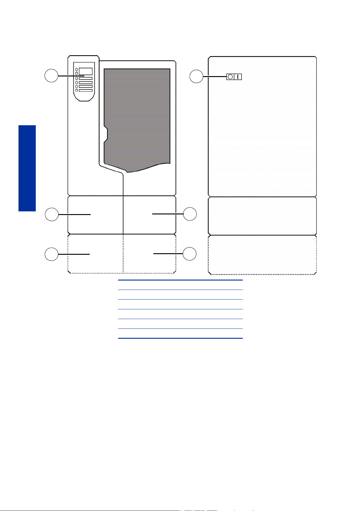
Front view
Left side view
2
3
4
5
1
6
Figure 1 Front and left side view of printer
1Display Panel
2 Material Bay, Support Side
3 Optional Material Bay, Support Side
4 Optional Material Bay, Model Side
5 Material Bay, Model Side
6Power ON/OFF Switch
4
Page 9
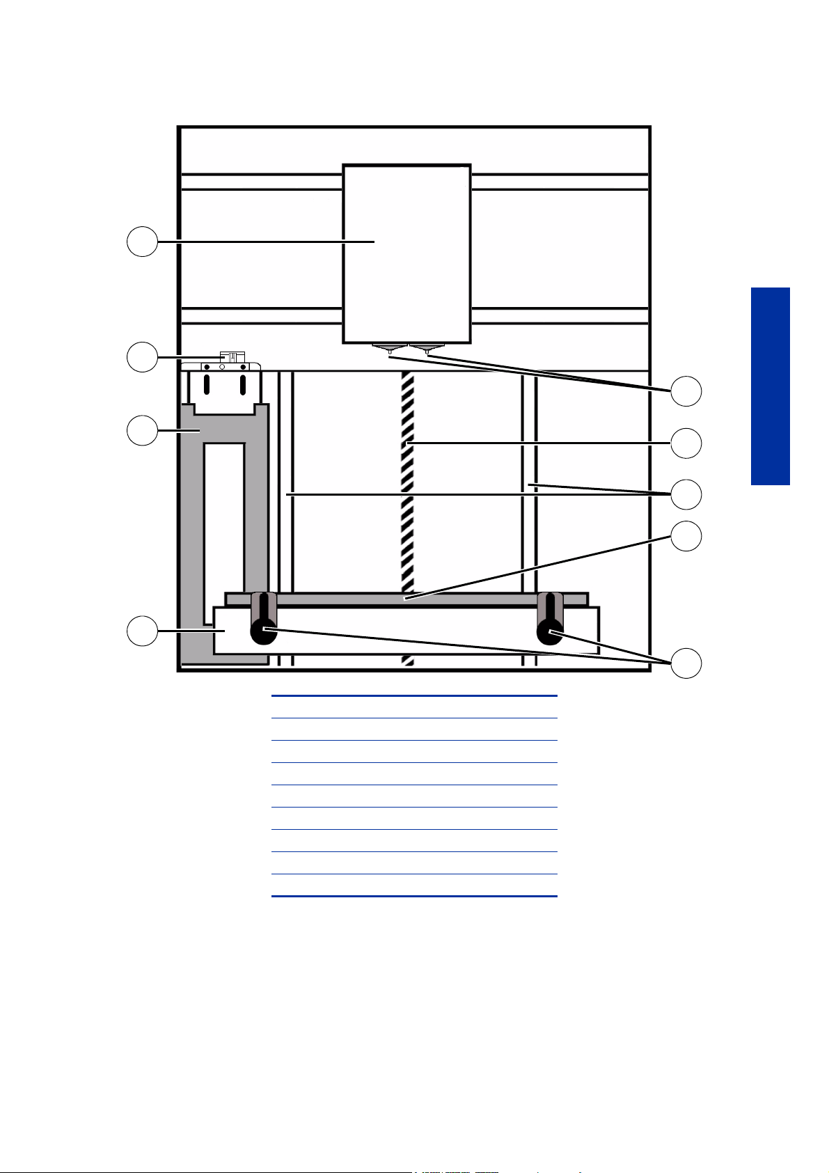
Figure 2 Interior chamber - front view
2
5
3
4
6
7
8
9
1
Overview
1Extrusion Head
2 Tip wipe assembly
3Purge bucket
4 Z stage platen
5 Modeling base retainers (x2)
6 Modeling base
7 Z stage lead screw
8 Z stage guide rods
9Extrusion Tips
5
Page 10
Overview
1
2
3
4
5
6
7
8
9
10
11
12
13
14
15
16
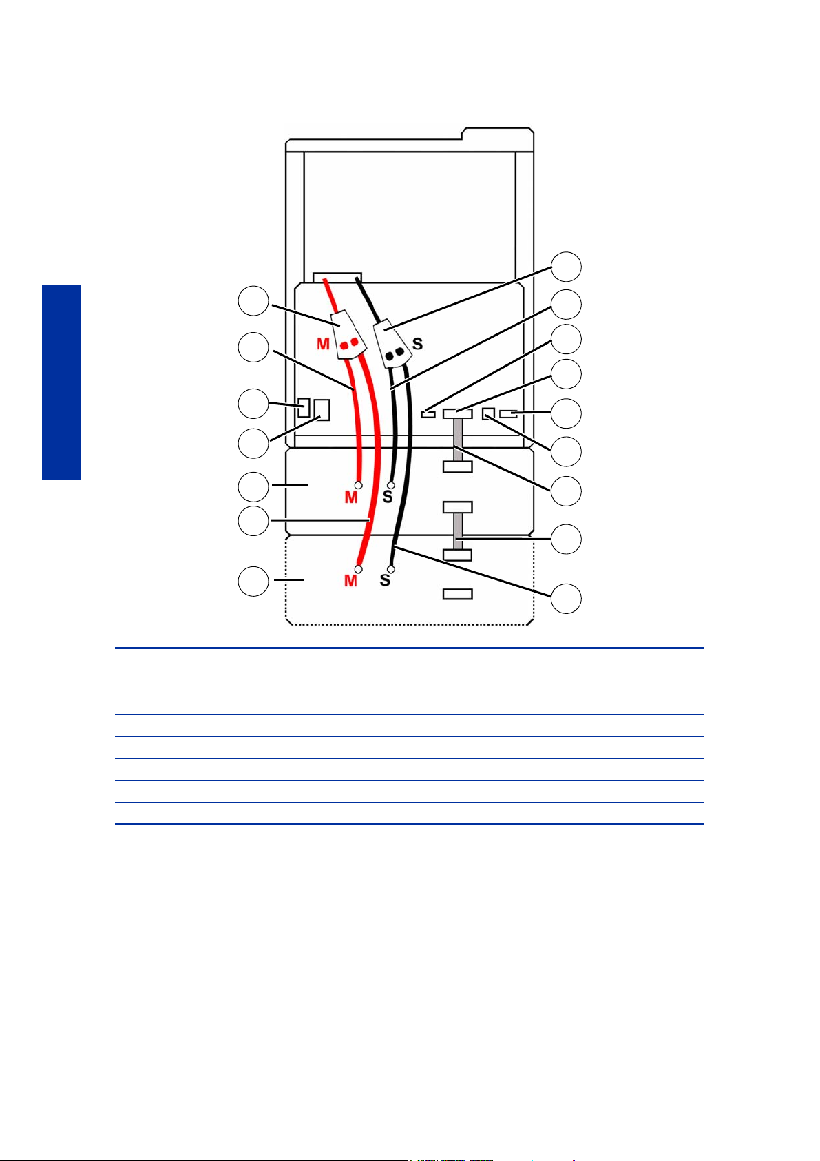
Figure 3 Rear view of printer
1 Model Material Y Connector 9 Support Material Tube
2Model Material Tube 10 UPS Connection
3 AC Power Cord Connector 11 Material Bay Cable Connector
4 Circuit Breaker 12 RJ-45 Network Connector
5 Material Bay 13 Diagnostics Cable Connector
6 Optional Model Material Tube 14 Material Bay Communications Cable
7 Optional Material Bay 15 Optional Material Bay Communications Cable
8 Support Material Y Connector 16 Optional Support Material Tube
6
Page 11
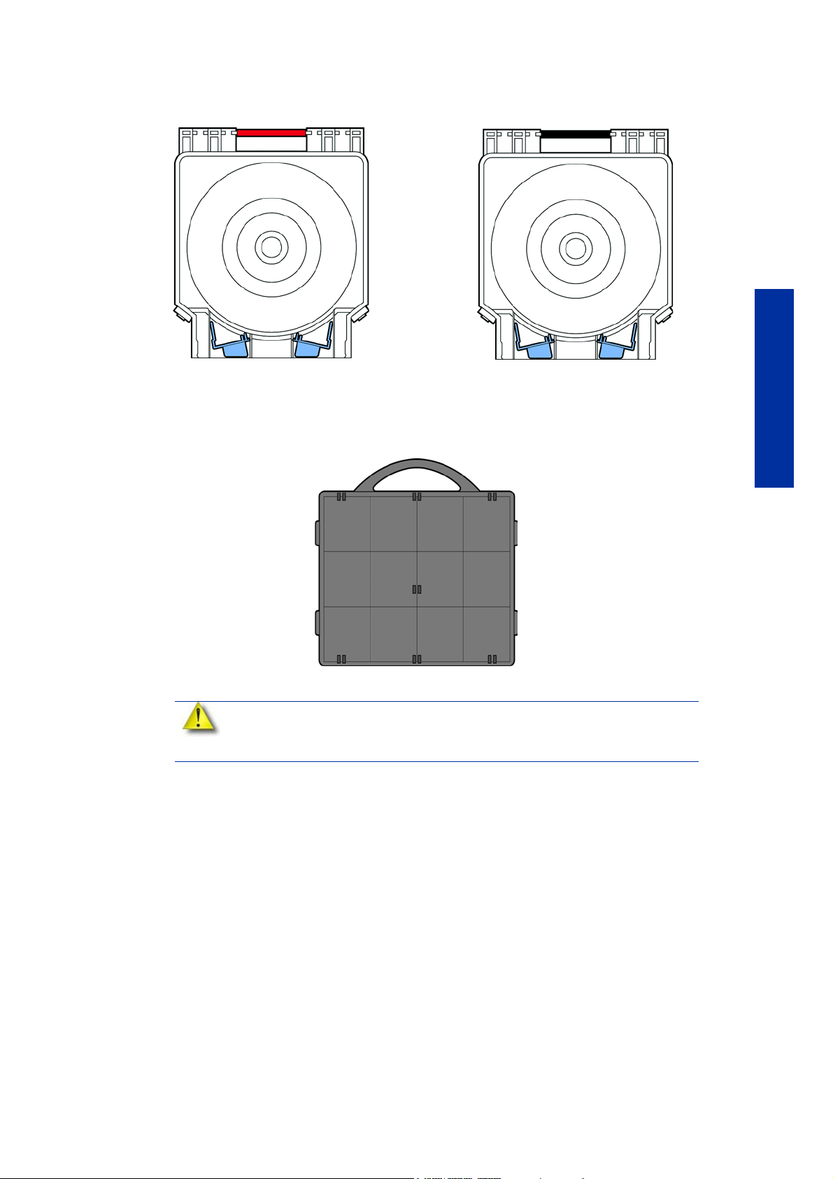
Figure 4 Material carriers
Support material carrier
Model material carrier
Modeling base
Figure 5 Modeling base
CAUTION: DO NOT reuse modeling bases. If a modeling base is reused,
calibration errors, poor part quality, and loss of extrusion may occur.
Additional modeling bases are available from your HP reseller.
Overview
7
Page 12
Overview
2
1
3
6
5
15
14
13
10
9
11
12
7
4
8
A
B
C
D
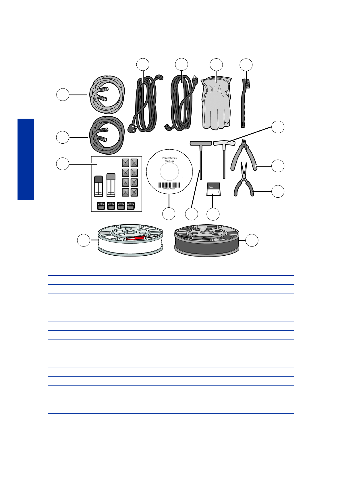
Figure 6 Startup Kit contents
1 Crossover cable (orange)
2 Network cable (blue)
3 Tip replacement kit (A. Support tip B. Model tip C. 8 Tip shields D. 4 Tip wipe assemblies)
4Model material spool
5Startup DVD
6 1/8 inch T-Handle wrench (red)
710x magnifier loupe
8 Support material spool
9 Needle nose pliers
10 Cut te rs
11 7/64 inch T-Handle wrench (yellow)
12 Wi re br u s h
13 G l o v e s
14 Power cord (Euro)
15 Pow e r c o r d ( UK )
8
Page 13
Finding more information
World Wide Web
Additional information is available at:
http://www.hp.com/go/3dprinter/knowledgecenter
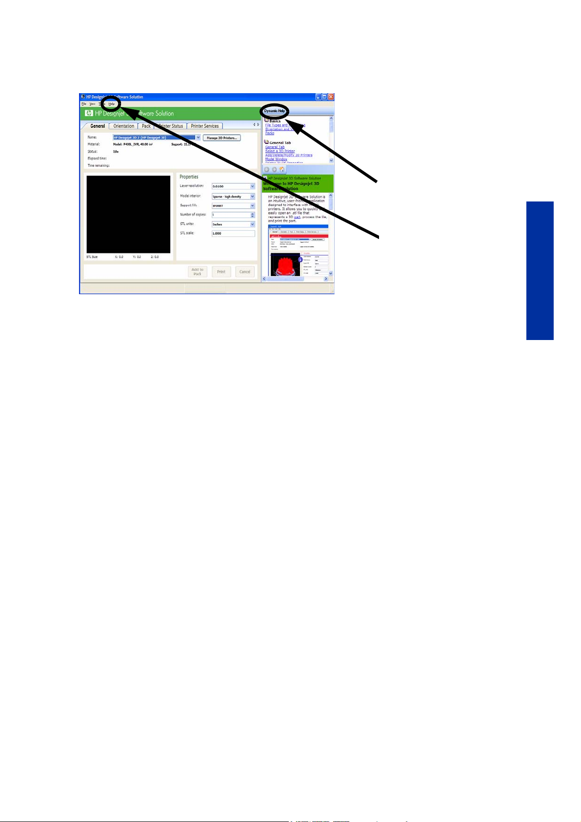
HP Designjet 3D Software
Solution Online Help
Simple operating
instructions for HP Designjet
3D Software Solution are
available in HP Designjet
3D Software Solution
Dynamic Help. You can
also see HP Designjet 3D
Software Solution Help from
the menu bar -
Help>Contents
Overview
9
Page 14

Setup
Set up the printer and material bay(s) per assembly instructions included with printer.
Installing software
There are two software programs that work with HP Designjet 3D and HP Designjet Color 3D:
1. HP Designjet 3D Software Solution, installed on your workstation, processes the STL files for
printing and communicates with the printer from your workstation.
2. System firmware, the operating software installed on the printer, controls printer functions.
Installing HP Designjet 3D Software Solution:
1. Locate the Startup DVD from startup kit and insert into workstation (PC).
Setup
2. Click the Install HP Designjet 3D Software Solution:
3. Follow prompts to finish loading HP Designjet 3D Software Solution on the workstation.
Installing firmware to the workstation:
1. Click the Install Firmware button to load firmware to your workstation. You will be asked to
load this firmware to your printer later.
2. Follow prompts to finish installing firmware on the workstation.
3. Install firmware to the printer, see “Installing Firmware on printer” on page14
Networking the printer
There are two methods of connecting your printer to your workstation, over a network or with a
direct connection to your workstation.
Connecting through a network:
1. Locate the network cable (blue) from the startup kit.
2. Connect the network cable between the printer and the network hub.
3. Establish communication, see “Establishing communication on a dynamic network:” on
page11 if you have a dynamic network, or “Establishing communication on a static
network:” on page11 if you have a static network.
button.
Connecting directly to a workstation:
1. Locate the crossover cable (orange) from the startup kit.
2. Connect the crossover cable between the printer and the network port on your workstation.
3. Establish communication, see “Establishing communication on a static network:” on
page11
10
Page 15

Establishing network communication with the printer
You will need to establish network communication between your workstation and printer before
you can send files to be built. How you establish this communication with an IP address is
dependent upon how your network and workstation are configured. If your network is
configured for DHCP (Dynamic Host Configuration Protocol), your DHCP server will
automatically assign a Dynamic IP address to your printer. This is the default setting for your HP
Designjet printer and commonly used in large networks. In some situations you may need to
manually enter a Static IP address for your printer and record the IP address in the HP Designjet
3D Software Solution. Static IP addresses are frequently used for smaller networks or for direct
connection between your workstation and printer. Follow the instructions below to configure
your workstation and network.
Establishing communication on a dynamic network:
If you are on a dynamic network (or not sure of your network type) follow these steps to allow HP
Designjet 3D Software Solution to find your printer and establish communication.
1. Connect a network cable between the printer and a network hub.
2. Make sure the printer is ON and determine the Unique Device Name (UDN) for your
printer.
a. From Idle (or Ready to Build), press Maintenance on the display panel. The display
will show Maintenance and the software version.
b. From the display panel press System.
c. From the display panel press Set Network. The top window will display: Network
Admin - Dynamic IP Address; UDN.
d. The Unique Device Name (UDN) for your printer is listed here. This is preset at the
factory and cannot be changed.
3. From your workstation, start the HP Designjet 3D Software Solution.
Setup
4. From the General tab, click the Manage 3D Printers button.
5. Click the Add from Network button in the lower right corner of the window.
6. A new window, A dd 3D Printer, should list your printer in the main window (identified by
its UDN). Click on the printer in this window and enter a name and location in the lower
portion of the window.
7. Click Add Printer and you are ready to print. Close the Add 3D Printer window.
NOTE: If your printer is not displayed in the “Add 3D Printer” window, you are
not using a dynamic network and you will need to set up a static network
address.
Establishing communication on a static network:
If you are using a static network or connecting the printer directly to a workstation, you will need
to enter the static IP address information into the workstation and the printer. If you are using a
static network and your computer already has network access, see “Setting the static network
on printer:” on page13
1. Set the static IP address information in the workstation:
a. For Windows XP, see “Setting the static network in Windows XP:” on page12
b. For Windows Vista, see “Setting the static network in Windows Vista:” on page12
c. For Windows 7, see “Setting the static network in Windows 7:” on page12
2. Set the static IP address information in the printer, see “Setting the static network on
printer:” on page13
3. Establish communication, see “Establish communication:” on page13
11
Page 16

Setting the static network in Windows XP:
1. From your workstation open the Control Panel and double click on Network Connections.
2. Right click on Local Area Connection and then left click on Properties.
3. Select Internet Protocol (TCP/IP) from the list.
4. Click on the Properties button.
5. Click on the Use the following IP address option.
6. Enter the IP Address, Subnet Mask and Default Gateway. Contact your IT Administrator or
Internet Service Provider for details regarding IP address information. The IP address should
be different from the workstation, the default gateway and subnet mask should match the
workstation. Enter the IP address, default gateway and subnet mask.
7. Click on the OK button when finished. Close any open networking windows.
Setting the static network in Windows Vista:
1. From your workstation click on the Start Menu.
2. Click on the Control Panel button.
3. Double click on Network and Internet.
4. Double click on the Network and Sharing Center icon.
5. Left click on Manage network connections.
Setup
6. Right click on the Local Area Connection icon then left click on Properties.
7. Select Internet Protocol Version 4 (TCP/IPv4) from the list.
8. Click on the Properties button.
9. Click on the Use the following IP address option.
10. Enter the IP address, Subnet Mask and Default Gateway. Contact your IT Administrator or
Internet Service Provider for details regarding IP address information. The IP address should
be different from the workstation, the default gateway and subnet mask should match the
workstation. Enter the IP address, default gateway and subnet mask.
11 . Click on the OK button when finished. Close any open networking windows.
Setting the static network in Windows 7:
1. From your workstation click on the Start Menu.
2. Click on the Control Panel button.
3. Double click on Network and Internet.
4. Double click on the Network and Sharing Center icon.
5. Double click Local Area Connection.
6. Click on the Properties button.
7. Select Internet Protocol Version 4 (TCP/IPv4) from the list.
12
8. Click on the Properties button.
9. Click on the Use the following IP address option.
10. Enter the IP address, Subnet Mask and Default Gateway. Contact your IT Administrator or
Internet Service Provider for details regarding IP address information. The IP address should
be different from the workstation, the default gateway and subnet mask should match the
workstation. Enter the IP address, default gateway and subnet mask.
11 . Click on the OK button when finished. Close any open networking windows.
Page 17

Setting the static network on printer:
1. Obtain your static network address from your Network Administrator.
2. From Idle (or Ready to Build), press Maintenance on the display panel. The display will
show Maintenance and the software version.
3. Press System.
4. Press Set Network. The top window displays: Network Admin - Static IP Address; UDN.
5. Press Static IP to display default settings.
IP Address:172.016.075.020 or 198.000.000.001
NM Address:255.255.000.000
GW Address:172.018.100.002
NOTE: These values are the factory defaults and MUST be changed. If these
values are not changed the printer will continue to restart until they are
changed.
NOTE: The IP address should be different from the workstation, the default
gateway and subnet mask should match the workstation. Enter the IP address,
default gateway and subnet mask.
6. Update the IP address:
Press Increment to increase the value one digit at a time.
Press Next Digit to move the cursor one place to the right.
Press Last Digit to move the cursor one place to the left.
7. Use the three functions listed above to set your IP address.
8. After setting the final digit of the Internet Protocol (IP) address, move the cursor one more
place to the right. The cursor moves to the Netmask (NM) address. Follow the same steps
for setting the Netmask (NM) and Gateway (GW) addresses.
9. When you have finished setting the addresses, press Done. The display will show: Change
IP, Netmask and Gateway?
10. Press Yes. The panel then displays Resetting Network.
11 . Press Done until Idle is displayed.
Establish communication:
1. From your workstation, start the HP Designjet 3D Software Solution.
a. From the General tab, click the Manage 3D Printers button.
b. Click the Add from Network button in the lower right corner of the window.
c. A new window, Add 3D Printer , should list your printer (identified by its UDN). Click
on the printer in this window and enter a name and location of your choice in the
lower portion of the window.
d. Click Add Printer to complete. Close the Add 3D Printer window.
Setup
2. If your printer is not displayed in the Add 3D Printer window, you will need to add the
printer IP address manually.
a. From the General tab, click the Manage 3D Printers button.
b. Click the Add Manually button in the lower right corner of the window.
c. In the Add 3D Printer window, enter a name and location of your choice in the
appropriate fields.
d. Enter the IP Address for your printer in the appropriate field. It will be the same
address as entered in step 6.
13
Page 18
Setup
e. Select your printer type from the drop down list, either HP Designjet 3D or HP
Designjet Color 3D.
NOTE: If you only have one printer connected, it will be the only printer in the
list.
f. Click Add Printer and close the Add 3D Printer window.
3. If you are unable to connect the printer to your workstation, contact your Network
Administrator.
Installing Firmware on printer
1. From the display panel, press Maintenance.
2. Press System.
3. Press Load Upgrade. “Send upgrade from workstation” and the printer IP address will be
displayed.
4. From your workstation, open the HP Designjet 3D Software Solution by double clicking on
the HP Designjet 3D Software Solution icon.
5. Click the Printer Services tab.
6. Select your printer from the drop down list then click the Update Software button.
7. Navigate the HP Designjet 3D Software Solution to the directory where the firmware file is
located and select the HP Designjet 3D.upg file for HP Designjet 3D or select the HP
Designjet Color 3D.upg file for HP Designjet Color 3D. Firmware will now begin to
download to the printer.
8. When firmware verification is complete, the printer display will show Reboot to complete
upgrade? Press Yes. The printer will then load the firmware then reboot and return to Idle.
NOTE: Loading firmware will take approximately 10 minutes.
Adding the second HP Designjet 3D Material Bay
You have the option of adding a second material bay to extend printing times without having to
reload material while the model is printing.
Installing the HP Designjet 3D Material Bay:
1. Remove the HP Designjet 3D Material Bay, material bay cable, material spools and
material carriers from the box.
2. Unload the model and support material from the printer.
3. Open the material bay doors by gently pressing in to release and pulling outwards.
4. Remove the material carriers by first pushing them in to unlatch and then pulling them
outwards.
5. Place the carriers on a flat stable surface.
CAUTION: Do not push the material through the material guide back into the
carrier, doing so can cause material to break or become tangled.
14
6. Open the carriers.
7. Rotate the spools to rewind the material, leaving 2 inches (50mm) remaining at the material
guide. See Figure 7.
Page 19
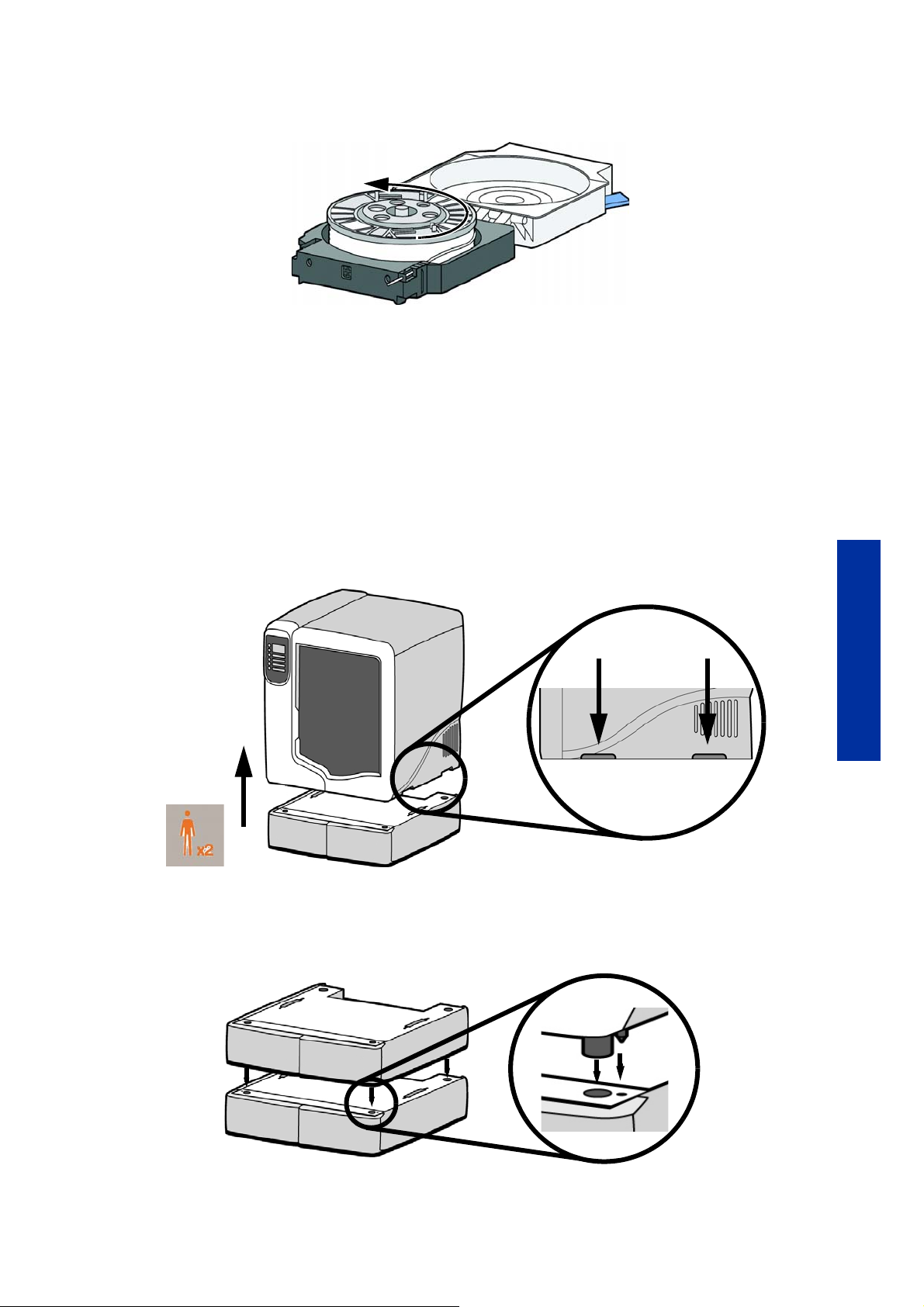
Figure 7 Rewinding the material spool
8. Using a cutters, cut the excess 2 inches (50mm) of material from the material guide. leaving
a blunt end.
9. Power the printer off at the power switch.
10. When the display is blank and the printer has shut down, turn the circuit breaker to the OFF
position.
11 . Disconnect the power cable, network cable and material bay cable.
12 . Disconnect the model and support material tubes from the printer and the material bay by
pressing in on the coupler ring and pulling the tubes outward.
13 . With 2 people, use the handgrips to lift the printer off of the material bay and place on a
flat stable surface. See Figure 8.
Figure 8 Separating the printer and material bay
14 . Position the second material bay on top of the existing material bay. Be sure the feet and
pins are properly aligned. See Figure 9.
Figure 9 Positioning material bays
Setup
15. With 2 people, position the printer on to the top of the material bays. Be sure the feet and
pins are properly aligned. See Figure 10.
15
Page 20
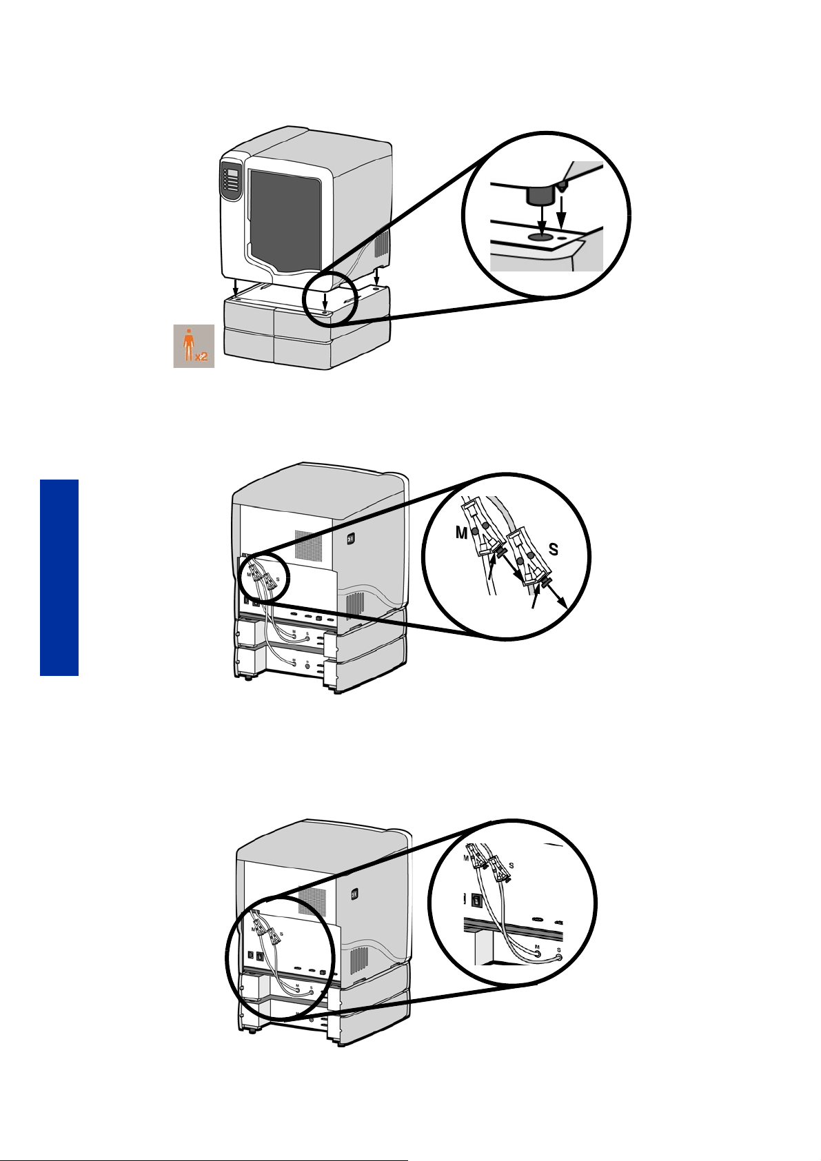
Figure 10 Positioning printer
16. Remove the black plugs from the model and support Y blocks by pushing in on the coupler
rings and pulling outward. See Figure 11.
Figure 11 Removing the Y block plugs
Setup
17. Connect the short red striped material tube (M1) from model (M) coupler of upper material
bay to left side of model Y block by inserting firmly into red couplers. Gently pull the tube
to ensure it is properly inserted.
18 . Repeat with the short black striped (S1) material tube for support side. See Figure 12.
Figure 12 Connecting the short material tubes
16
Page 21
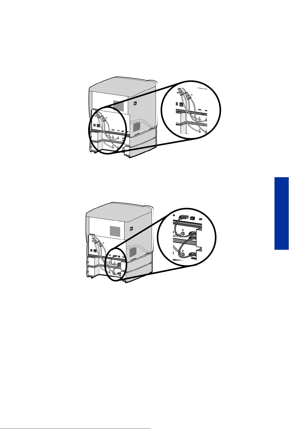
19. Connect the long red striped material tube (M2) from model (M) coupler of lower material
bay to right side of model Y block by inserting firmly into red couplers. Gently pull the
tube to ensure it is properly inserted.
20. Repeat with long black striped (S2) material tube for support side. See Figure 13.
Figure 13 Connecting the long material tubes
21. Connect a material bay cable between the printer and the top connector on the upper
material bay.
22. Connect the other material bay cable between the bottom connector of the upper material
bay to the top connector of the lower material bay. See Figure 14.
Figure 14 Connecting the material bay cables
23. Connect the power cable and network cable.
24. Switch the circuit breaker to the ON position.
25. Power the printer ON at the power switch.
26. After the printer has booted up, you may need to reload the printer firmware. If the printer
displays “Send Upgrade from Workstation”, See “Updating printer firmware:” on page32.
27. Insert model and support material spools into the new material carriers.
Setup
28. From display panel press Material. Display will show Add/Remove.
29. Open material bay doors and push both red handled model carriers into right side of the
material bays until they latch.
30. Push both black handled support carriers into left side of the material bays until they latch.
17
Page 22

31. Press Load Selected. The printer will load the first material bay and prepare the second
material bay for automatic loading. When the printer has finished loading material, S1
and M1 will be marked with asterisks. All material bay LED’s will be solid.
NOTE: Material may take up to ten minutes to load.
32. When finished loading material press Done. Display will show Idle and amount of material
remaining for model and support in both material bays.
Setup
18
Page 23
Operation
1
3
2
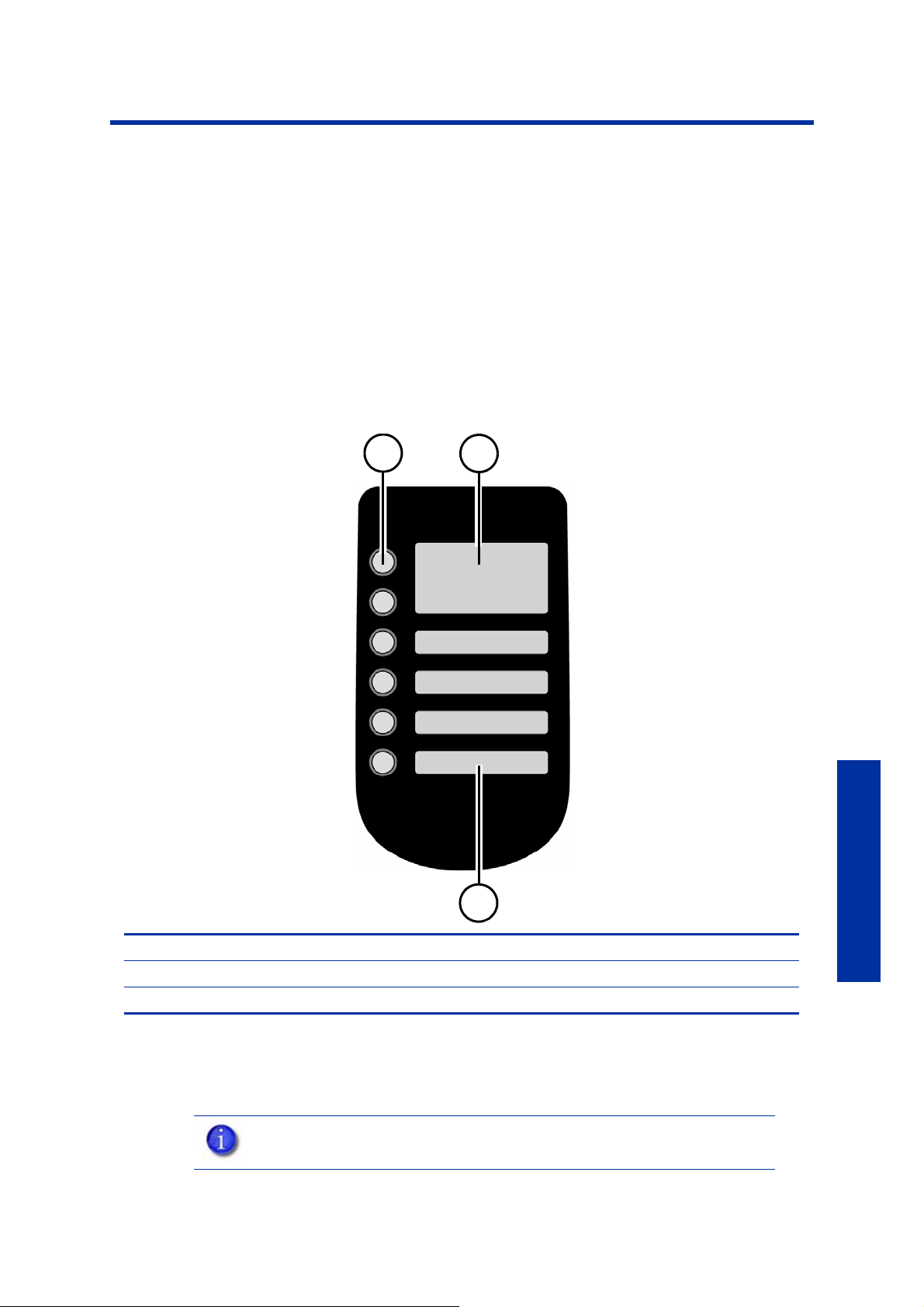
Display panel and keypad
The main user interface for the printer is the display panel and keypad. See Figure 15.
Figure 15 Display panel and keypad
1 Keypad buttons
2 Main display window
3Lower display windows
The HP Designjet 3D and HP Designjet Color 3D display panel and keypad consist of a multipleline LCD window with two buttons used for scrolling through messages and four single-line
windows, each with one button for making selections. The top line in the upper window always
shows the printer status.
NOTE: If an item is blinking in the lower displays, the blinking item is usually
the next most logical selection.
Operation
19
Page 24

System firmware overview
Idle
status
Material
Standby
Maintenance
System
Setup
Machine
• Set Network
• Test Parts
• Load Upgrade
• Lights Always On
• Select Language
• Gantry
• Head
• Tips
• Pause
• Lights Off
• Show Time
• Auto Power Down
• Load Material
• Unload Material
• Replace Material
Wait for Part
Start Part
Building
status
• Idle: If there is no part being built and no part in the build queue, the display will show that
the printer is Idle.
• Wait for Part or Start Part: If the printer is in Idle and the build queue is empty, you can set
it to wait for a part. If the printer has a part in the build queue, you can press Start Part to
start a build.
• Building: If the printer is building a part, you can choose to pause, set the lights either ON
or OFF, view the print time or material remaining and set the printer to auto power down.
• Material: From this section you can load material, unload material or replace material.
• Standby: From this section you can set the printer to Standby mode.
• Maintenance: From this section you can make changes to the System, Setup or Machine.
Figure 16 Display panel hierarchy
Operation
20
Page 25

HP Designjet 3D Software Solution overview
HP Designjet 3D Software Solution
• Auto orientation
• Part rotation
• STL scale
• Change views
• Insert Pause
• Insert CMB file
• Pack name
• Clear pack
• Printer status
• Job queue
• Manage queue
• Printer history
• Export configuration
• Printer time
• Printer password
• Printer information
• Update software
• Layer resolution
• Model fill style
• Support style
• Number of copies
• STL units
• STL scale
General tab
Orientation tab
Pack tab
Printer Status tab
Printer Services tab
• General tab: This section is where you can select the model fill, support style, change the
STL units and STL scale.
• Orientation tab: This section allows you to rotate, resize and auto-orient your parts. You
can also change the view and insert a pause.
• Pack tab: This section shows you which parts are in the pack for printing. You can add
parts, arrange the parts for a better fit or clear the pack from this section.
• Printer Status tab: This section shows you the amount of material remaining (both model
and support) as well as which parts are in the Build Queue.
• Printer Services tab: From this section you can check the printer history, set the printer time,
set the printer password, update printer software, get printer info and export configuration
files (files containing specific operating information regarding the printer).
Figure 17 HP Designjet 3D Software Solution hierarchy
NOTE: For detailed information refer to HP Designjet 3D Software Solution
Dynamic Help.
Operation
21
Page 26

Processing your STL file for printing
Opening your STL file with HP Designjet 3D Software Solution:
1. Create an STL file using your CAD software. Refer to your CAD software help section for
more information about converting your CAD drawings into STL files.
2. Open the HP Designjet 3D Software Solution.
3. From the File menu select Open STL...
4. Navigate to and select the STL file that you have created.
Selecting layer resolution:
Layer resolution can be changed on the HP Designjet Color 3D printer. Changing layer
resolution will effect surface finish and build times. Selecting a smaller layer resolution creates a
smoother surface finish, but takes longer to build. Layer resolution also affects the minimum wall
thickness. Minimum wall thickness applies to the horizontal (XY) plane of your part. If a feature
in an STL is smaller than the limit, the modeler will increase the size of the feature to the minimum
wall thickness.
Printer type Available layer resolutions Minimum Wall thickness
HP Designjet 3D .010 inch (.254 mm) .036 inch (.914 mm)
HP Designjet Color 3D .010 inch (.254 mm)
.013 inch (.3302 mm)
.036 inch (.914 mm)
.047 inch (1.194 mm)
Selecting model interior fill style:
This establishes the type of fill used for the interior areas of the part. There are three types of
model interior that you can choose from.
• Solid - Used when a stronger, more durable part is desired. Build times will be longer and
more material will be used.
• Sparse High Density - This is the default model interior style and is highly
recommended. Build times will be shorter, less material will be used and the possibility of
part curl for geometries with large mass will be greatly reduced.
• Sparse Low Density - The interior will be “honeycombed” or “hatched”. This style
Operation
allows for the shortest build times and lowest material usage but will decrease the strength
of the part.
Selecting support style:
HP Designjet 3D Support Material is used to support the model during the build process. It is
removed when the part is complete. Support styles will affect the support strength and build time
of the print. SMART support is the default support setting.
• Basic - May be used for most parts. Basic support uses a consistent spacing between
support toolpaths.
• SMART - minimizes the amount of support material used, reduces the build time, and
improves support removal for many parts. SMART supports use a wide spacing between
toolpath rasters and change the shape of the support region. As the supports descend from
the underside of the part feature to the base of the supports, the support region shrinks and
transforms to a simpler shape to reduce the amount of material used and the build time.
SMART supports are suitable for all parts, especially those with large support regions.
• Surround - The entire model is surrounded by support material. Typically used for tall, thin
models.
22
Page 27

Selecting the scale of your STL file:
Before you process a part for printing, you can change the size of the part within the build
envelope. Every part has a pre-defined size within the STL file. After you have opened the file
you can change the size of the part produced from the STL file by changing the scale. The scale
always relates to the original STL file size definition.
For example: a cube that is defined as 2 X 2 X 2 can be built to be 4 X 4 X 4 by simply
changing the scale to 2.0. If after changing the scale to 2.0, you decide that a size of 3 X 3 X 3
would be preferred, change the scale to 1.5 - the scale relates to the original size of 2.0, NOT
the resulting 4.0 from the first scale change.
Click within the scale input box to type a scale of your choice.
Selecting the orientation of your STL file:
The Orientation tab has an expanded preview window. It provides options for viewing a part,
measuring a part, orienting a part, processing a part and viewing the layers of a part. How a
part is oriented in the preview window will determine how the part is oriented when it prints.
Orientation impacts build speed, part strength, surface finish and material consumption.
Orientation can also affect the ability of HP Designjet 3D Software Solution to repair any
problems with the STL file.
You can choose to auto orient your part, which allows HP Designjet 3D Software Solution to
determine the best orientation for the part for the fastest build time and least material usage, or
you can manually change the orientation of your part.
Orientation Considerations:
• Build Speed - Closely related to material use. A lesser amount of supports will allow for a
faster build speed.
Another factor affecting build speed is the axis orientation. The printer can build faster
across the X-Y plane than it can along the Z axis. Orienting a part so that it is shorter within
the modeling envelope will produce a quicker build.
• Part Strength - A model is stronger within a layer than it is across layers. Depending
upon what features you want your part to demonstrate, you may need to orient your part to
have its greatest strength across a specific area. For example a tab that needs to be
pressed would be weakest if you are applying pressure across layers.
• Surface Finish - Much like orienting for strength, how the part is oriented will determine
how the surface finish will look and allow the printer to provide the smoothest finish for a
specific area. For example, if building a cylinder, orienting the cylinder upright will have a
smoother surface finish than building it on its side.
• STL File Repair - It is possible for an STL file to have errors while appearing to be trouble
free. If the STL file contains errors, HP Designjet 3D Software Solution may have problems
processing the file. HP Designjet 3D Software Solution has the ability to automatically
correct some STL file errors. How the part is oriented can impact this automated repair
function.
Operation
23
Page 28

Adding your STL file to the pack:
The Add to Pack button is found on the General, Orientation and Pack tabs.
When you click on the Add to Pack button, HP Designjet 3D Software Solution will add the file
that is currently in the preview window (General tab or Orientation tab) to the pack preview
window (Pack tab).
If the file in the preview window has not been processed for printing, processing will occur
before the file is added to the pack. Each additional click of the Add to Pack button will add
another copy of the file to the pack.
Printing your STL file:
The Print button is found on the General, Orientation and Pack tabs.
HP Designjet 3D Software Solution will now process all parts in the pack and create a CMB file
from which the printer will print the parts.
Building a part
If a part has not been sent to your printer for building, the build queue will be empty. If the build
queue is empty the display panel will show Idle or Ready to build.
Choose whether or not you want to start a build from a remote location or from the display
panel at the printer.
Starting a build from a remote location:
The lower display will show Wait for Part and it will be flashing.
1. From the display panel press Wait for Part. The display will ask Is Model Base Installed?
2. Insert a modeling base.
CAUTION: DO NOT reuse modeling bases. If a modeling base is reused,
calibration errors, poor part quality, and loss of extrusion may occur.
Additional modeling bases are available from your HP reseller.
3. Press Yes. Waiting for Part will now be on the display.
Operation
4. From your HP Designjet 3D Software Solution workstation, send a part to the printer. The
printer will automatically start to build the part. See “Processing your STL file for printing”
on page22 for detailed instructions.
Starting a build from the display panel:
If Wait for Part has not been activated, you can send the part to the printer and start the part
from the display panel after the part has been sent to the printer.
1. From your HP Designjet 3D Software Solution workstation, send a part to the printer. The
display will show Idle/Ready to Build and the name of the first file that is in the queue
waiting to be built.
24
2. Insert a modeling base.
CAUTION: DO NOT reuse modeling bases. If a modeling base is reused,
calibration errors, poor part quality, and loss of extrusion may occur.
Additional modeling bases are available from your HP reseller.
3. From the display panel press Start Model to start building the part.
Page 29
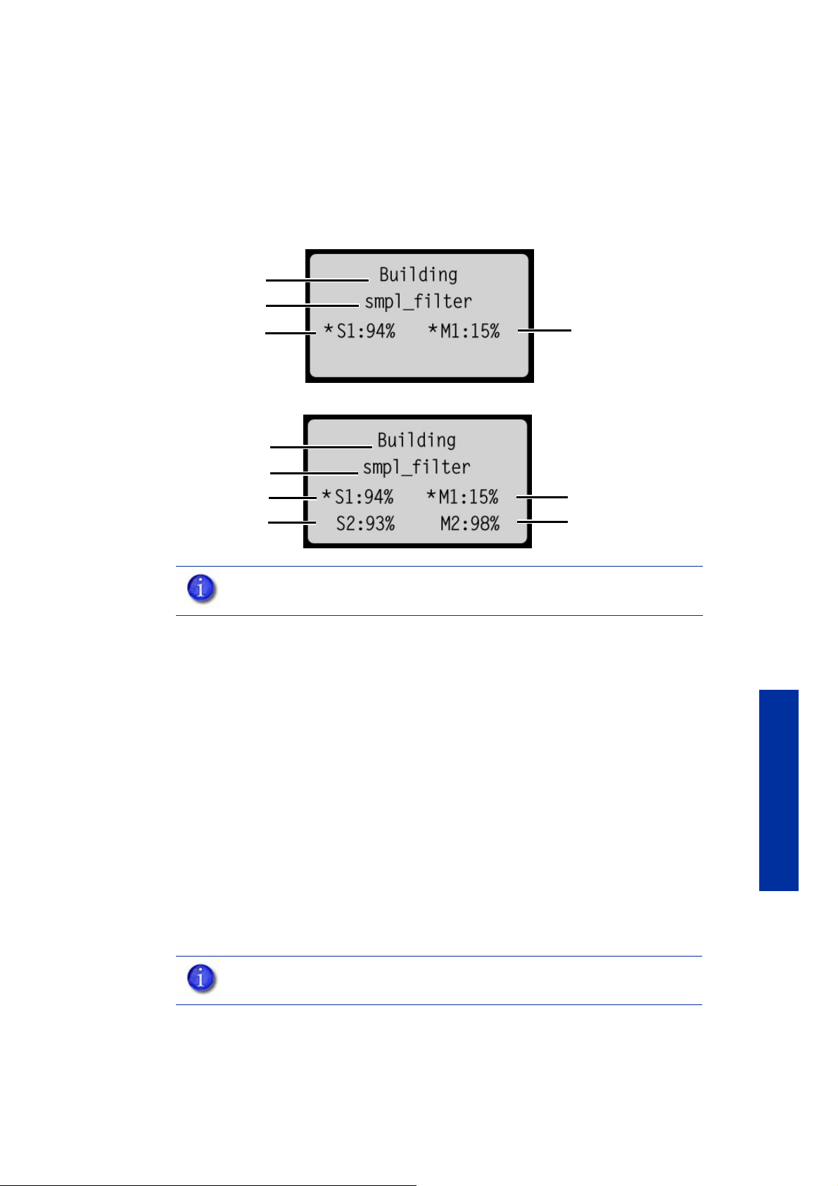
The display panel during build
Printer status
Model file name
Support material
remaining
Model material
remaining
Printer status
Model file name
Support material
remaining in bay 1
Support material
remaining in bay 2
Model material remaining
in bay1
Model material remaining
in bay2
Single material bay
Dual material bay
The top two lines of the display panel will show the printer status. See Figure 18. The bottom line
of the display panel will show the amount of model and support material that remains in the
carriers.
Figure 18 Display panel during build
Chamber Lights
When a part starts to build, the chamber lights are automatically ON. The default time-out for
the lights is 30 minutes. You can toggle the lights ON or OFF through the display panel.
You can set the chamber lights on permanently, however the chamber lights will return to factory
settings when power is cycled.
1. From Idle or Ready to Build, on the display panel press Maintenance.
Repeat this process to turn this option off.
Pausing a build
While building a part, you may want to pause the build to allow for material replacement. To
pause the build at any time, from the display panel press Pause.
NOTE: If a material amount is flashing, it indicates that the remaining material
will not be enough to complete the current build.
a. Press Setup.
b. Press Lights Always On.
NOTE: The printer will complete the current tool path before pausing.
Operation
Resuming after pause
If you have pressed Pause, and are ready to resume building the part, press Resume and the
printer will resume printing.
25
Page 30

Canceling a build
You can cancel a build at any time while the part is building.
1. From the display panel press Pause.
2. Once the printer stops building, press Cancel Build.
3. The display will ask Are you Sure? Press Yes.
4. The display will show Build Stopped followed by the file name. You will then be prompted
to remove the part and replace the modeling base.
5. Remove the part and replace the modeling base.
GLOVES: The modeling base will be hot, wear gloves when removing the
part from the printer.
6. Once the chamber door has been opened and closed, the display will ask Part Removed?
Press Yes ONLY after you have removed the part and replaced the modeling base.
CAUTION: If you press Yes before removing the part, the printer can be
damaged.
Removing a completed part
When the printer has completed building a part, the display will show Completed followed by
the file name. It will also show Remove Part and Replace Modeling Base.
GLOVES: The modeling base will be hot, wear gloves when removing the
part from the printer.
1. Open the chamber door.
2. Turn the modeling base retainers down and remove the modeling base by sliding out and
pulling up.
3. Insert a new modeling base by sliding in and pushing down, turn the retainers up to lock
Operation
the modeling base in place.
4. Close the chamber door.
5. After you have opened and closed the door, the display will show Part Removed? ONLY
after removing the part and replacing the modeling base, from the display panel press Yes.
CAUTION: If you press Yes before removing the part, the printer can be
damaged.
After you press Yes, the display will show the status as Idle or Ready to Build for the next part in
the queue.
Remove a part from the modeling base:
1. After removing the modeling base from the printer, firmly flex the modeling base back and
forth with your hands to loosen the part.
2. Pull the part off of the modeling base or use a putty knife to completely remove the part.
NOTE: Parts are easier to remove from the modeling base when still warm.
26
Page 31
Removing HP Designjet 3D Support Material
Purge bucket
HP Designjet 3D and HP Designjet Color 3D use HP Designjet 3D Support Material which is
designed to dissolve in a soap and water based solution. Your part is left with a smooth and
clean finish with the fine details intact. The support material can be removed by hand with
relative ease, but is designed to be dissolved from your parts for hands free finishing.
WARNING: Support material is sharp, wear safety glasses and gloves when
removing support material by hand.
Emptying the purge bucket
Empty the purge bucket after each build to avoid part quality issues or damage to the printer.
GLOVES: Wear gloves when emptying the purge bucket.
1. With a gloved hand, lift up on the purge bucket and pull it off of the two mounts. See
Figure 19.
Figure 19 Emptying the purge bucket
2. Empty the purge bucket.
3. Place the purge bucket over the two mounts and push down to lock in place.
CAUTION: When reinstalling the purge bucket, make sure that it locks on both
mounts and hangs flush with the chamber wall to avoid damage.
Operation
27
Page 32

Replacing material for single material bay
1. From the display panel press Material... The display will show Add/Remove and
S1(remaining%) and M1(remaining%). Asterisks will mark the currently active material
bays (the material bays that are currently loaded to the head).
2. Press Unload...
3. Select Unload both, Unload Model or Unload Support.
4. The printer will now unload material from the head. When the material has unloaded, you
will need to replace the material carriers.
5. Open the material bay doors by gently pressing in to release and pulling outwards.
6. Remove the material carriers by first pushing them in to unlatch and then pulling them
outwards.
7. Place the carrier on a flat stable surface.
CAUTION: Do not push the material through the material guide back into the
carrier, doing so can cause material to break or become tangled.
8. Open the carrier.
9. Rotate the spool to rewind the material, leaving 2 inches (50mm) remaining at the material
guide. See Figure 20.
Figure 20 Rewinding the material spool
10. Using a cutters, cut the excess 2 inches (50mm) of material from the material guide leaving
a blunt end.
Operation
11 . Replace the material spool.
12 . Close and latch the carrier.
13 . Once the material carriers have been replaced press Load...
14 . Select Load Model, Load Support or Load both.
15. After material has been loaded to the head press Done...
Replacing material for dual material bays
1. From the display panel press Material... The display will show Add/Remove and
S1(remaining%), S2(remaining%) and M1, M2 (remaining%). Asterisks will mark the
currently active material bays (the material bays that are currently loaded to the head).
28
2. Press Unload...
3. Press Unload both, Unload Model or Unload Support.
4. The printer will now unload material from the head. When the material has unloaded, you
will need to replace the material carriers.
5. Open the material bay doors by gently pressing in to release and pulling outwards.
Page 33

6. Remove the material carriers by first pushing them in to unlatch and then pulling them
outwards.
7. Place the carrier on a flat stable surface.
CAUTION: Do not push the material through the material guide back into the
carrier, doing so can cause material to break or become tangled.
8. Open the carrier.
9. Rotate the spool to rewind the material, leaving 2 inches (50mm) remaining at the material
guide. See Figure 21.
Figure 21 Rewinding the material spool
10. Using a cutters, cut the excess 2 inches (50mm) of material from the material guide, leaving
a blunt end.
11 . Replace the material spool.
12 . Close and latch the carrier.
13 . Once the material carriers have been replaced press Load...
14 . You can select which carriers you want to load to the head by selecting Next Model or Next
Support. When done selecting press Load Selected.
15. The printer will now load the selected material bays and prepare the other bays for
automatic loading. After they are done loading and preparing, press Done... the display
will show Wait for Part or Ready to Build.
Material bay LEDs
The table below will show the status indicated by the LEDs.
On
Off
Blinking
Material currently loaded to the head
No carrier present
Carrier present and ready to be loaded
Carrier needs replacement (is empty or has an error)
Operation
29
Page 34

Replacing material spools
Removing a spool of material from the carrier:
1. Place the carrier on a flat stable surface.
2. Unlatch the carrier and open.
3. Remove the spool of material. Discard any pieces of material that may remain in
the carrier.
4. Remove the material guide and recycle. See “Removing the EEproms from the material
guides” on page62
5. Recycle the empty material spool. See “Recycling” on page61
6. Install a new material spool into the material carrier.
Storing material spools
If you will not be using the printer for more than 72 hours, unload and store model and support
material in the storage bags provided to prevent moisture absorption.
1. Unload material from the printer.
2. Open the material bay doors by gently pressing in to release and pulling outwards.
3. Remove the material carriers by first pushing them in to unlatch and then pulling them
outwards.
4. Place the carrier on a flat stable surface.
CAUTION: Do not push the material through the material guide back into the
carrier, doing so can cause material to break or become tangled.
5. Open the carrier.
6. Rotate the spool to rewind the material, leaving 2 inches (50mm) remaining at the material
guide. See Figure 22.
Figure 22 Rewinding the material spool
Operation
7. Using a cutters, cut the excess 2 inches (50mm) of material from the material guide, leaving
a blunt end.
30
8. Locate the two material retaining clips on the carrier. See Figure 23.
Page 35

Figure 23 Material retaining clips
Material retaining clips
Place clip and push down to lock in place
9. Place the material guide in the material guide slot on the spool. See Figure 24.
10. Place the material in the material notches. See Figure 24.
Figure 24 Material guide slot and notches
11 . Cut the excess material from material guide.
12 . Place the material retaining clips on the spool before removing the spool from the carrier.
See Figure 25.
a. Push the material retaining clips over the material and clip on to
the material spool.
b. Push the material retaining clips down until they lock in place.
Figure 25 Installing material retaining clips
13 . Remove the material spool from the material carrier. See Figure 26.
Operation
31
Page 36

Figure 26 Properly installed material retaining clips.
14 . Place the material spool in the storage bag that came with the material carrier.
NOTE: When not loaded in the printer, always store material spools in the
material carrier or the storage bag that came with the carrier to prevent
moisture absorption.
Auto power down
You can set the printer to automatically power down when a build is complete. This option will
save energy usage.
1. While the printer is building, press the Auto Power Down button.
2. Turn the power switch, located on the left side of the printer, to the OFF position.
The printer will display Auto Power Down Mode and the printer will power down as soon as the
build is complete.
Cancelling auto power down:
1. Turn the power switch back to the ON position.
Powering off
To power off the printer, turn the power switch to the OFF position. You can do this at anytime
without harming the printer. No other steps are necessary. If this is done while the printer is
building a part, the current part will not be completed.
Operation
NOTE: System cooling fans and lights will continue to operate for several
minutes after the switch has been turned off.
Resuming operations from Standby mode
After several minutes of inactivity, the printer will enter Standby mode. During Standby, the head
temperature will decrease to conserve energy.
From the display panel press Resume.
Updating printer firmware:
Check http://www.hp.com/go/3dprinter/knowledgecenter for printer firmware updates. If
there is an upgrade to the printer firmware, download the upgrade and install on the printer.
Installing the firmware:
1. From the printer display panel, press Maintenance.
2. Press System.
32
Page 37

3. Press Load Upgrade. The printer will then display “Send upgrade from workstation”
followed by the printer’s IP address.
4. Open HP Designjet 3D Software Solution and click on the Printer Services tab.
5. Click on the Update Software button. HP Designjet 3D Software Solution will now connect
to the printer and will prompt you to locate the upgrade file. Navigate HP Designjet 3D
Software Solution to the directory where the upgrade file is located. The update will
automatically be loaded on to the printer. After the update has been loaded, the display
will show Verifying update.
6. When verification is complete, the display will show Reboot to complete. Press Yes. The
printer will now reboot and return to Idle.
7. Press the Maintenance button and verify the updated version was installed correctly then
exit maintenance.
33
Operation
Page 38

Maintenance
Startup kit tools
The startup kit contains a set of tools used to help you maintain the printer. The following is a list
of the tools contained in the startup kit.
• Needle nose pliers
• T-Handled allen wrench - 1/8 inch
• T-Handled allen wrench - 7/64 inch
• Gloves (Leather)
• Cutters
• Brush
• Magnifier
Preventive Maintenance
Daily
Empty the purge bucket
Inspect the tip wipe assembly
Inspect the tip shields
Remove debris buildup
Maintenance
Vacuum build chamber
Empty the purge bucket after each build has completed.
After each build you should inspect the tip wipe assembly to make sure there is no material build
up. If there is material build up, clean the tip wipe assembly. Material build up on the tip wipe
assembly can cause part quality issues. See “Tip wipe assembly” on page 5-35
After each build you should inspect the tip shields for damage or material build up. If there is
material build up remove it as needed. If the material will not break free or there is damage to
the tip shield, replace the tip shield. See “Tip shield replacement” on page 5-37
Remove all material buildup on the Z platform and around the lead screw. Failure to do so could
cause the base to not be level or the Z platform to jam at its upper limit.
Vacuum the build chamber to remove all debris and purged material.
Clean door
Do not use ammonia based glass cleaner on the door. It will damage the acrylic window.
34
CAUTION: ONLY use acrylic cleaner.
Page 39

500 Hour maintenance
Preventive Maintenance Alerts will be displayed on the workstation at the 500 hour time interval
as a reminder to perform preventive maintenance. See Figure 27.
Figure 27 Preventive Maintenance Alert
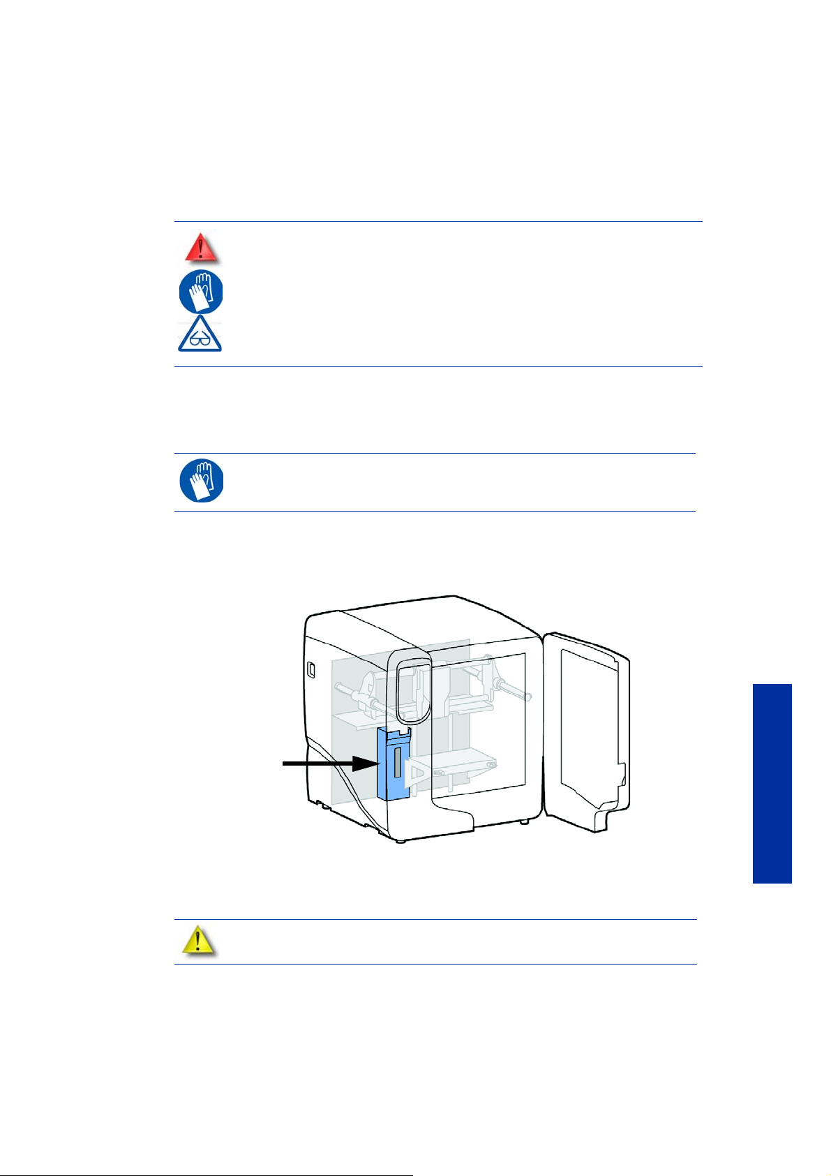
Tip wipe assembly
The tip wipe assembly should be replaced approximately every 500 hours.
1. Completely power down the printer.
2. Move the head to the right of the printer to gain access to the tip wipe assembly.
Figure 28 Move the toggle head to the right
3. Remove the tip wipe assembly by lifting the assembly up and out of the printer. Discard this
tip wipe assembly. See Figure 29.
35
Maintenance
Page 40

Figure 29 Replacing the tip wipe assembly
1. Place the new tip wipe assembly over the two mounting posts making sure the assembly is fully
installed. See Figure 30.
Figure 30 Installing tip wipe assembly
Maintenance
36
4. Power the printer back up.
Page 41

Tip shield replacement
New shield Worn shield
Press tabs in to remove
head cover
Head cover
Tip shields can become worn or damaged over time. This can have a negative impact on the
surface finish and detail of models. Replace the tip shields every 500 hours.
Figure 31 Tip Shield damage
1. Enter Head Maintenance.
a. From the display panel press Maintenance.
b. Press Machine.
c. Press Head. The head will come to rest in the center of the
chamber and the Z platform will change position.
GLOVES: The head area is hot, wear gloves when working in this area of the
printer.
2. Remove the head cover by pressing the tabs in and pulling away from the head. See Figure 32.
Figure 32 Head cover tab locations
2. Position the blade of a small screwdriver between the tip shield and tip plate. Use the blade
of the small screwdriver to separate the tip shield from the tip plate. See Figure 33.
Maintenance
37
Page 42

Figure 33 Tip Shield removal
Insert small standard
screwdriver to pry tip
shields from tips.
Tip shield
Tip plate
Clean the tips using a wire brush.
3. Clean the tip using the wire brush supplied with the Startup Kit to remove any debris. See
Figure 34.
Figure 34 Clean tips with wire brush
Maintenance
38
4. Install a new tip shield by pushing it, by hand, over the exposed tip, keeping the slotted
end towards the back of the tip. See Figure 35.
Page 43
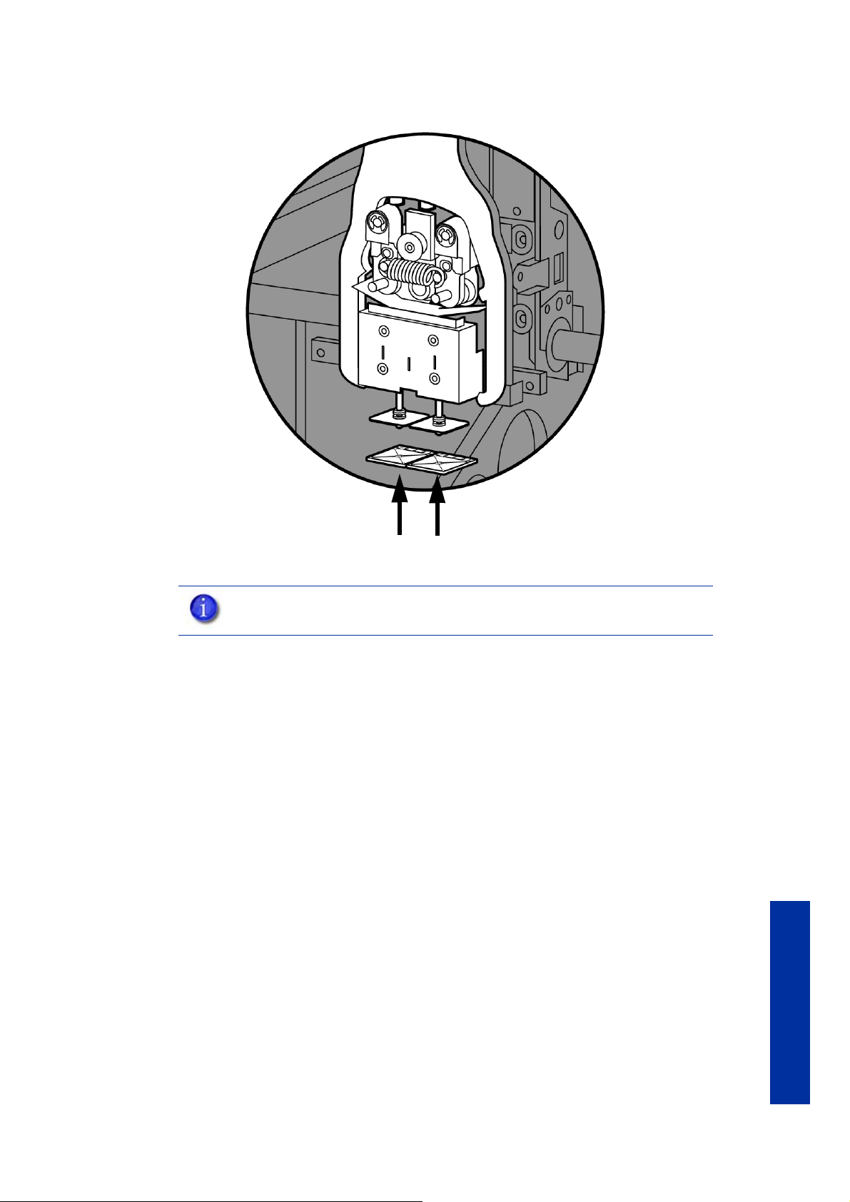
Figure 35 Tip Shield installation
5. Replace head cover.
NOTE: If the head cover is not replaced the printer may not function properly.
6. Exit Maintenance, press Done until back at Idle.
39
Maintenance
Page 44

Remove debris from the Filament Present switch
Support side Filament Present Switch
Model side Filament Present Switch
There may be a time when the Filament Present switch needs to be cleared in addition to the
500 hour maintenance. For example, if a Material Error-Filament blocked message appears
on the display panel; the recommendation may be to clear debris from the Filament present
switch.
1. Unload material from the printer.
2. Open the material bay doors by gently pressing in to release and pulling outwards.
3. Remove the material carriers by first pushing them in to unlatch and then pulling them
outwards.
4. Disconnect the material tubes from the rear of the material bay(s). Leave them attached to
the Y block.
5. Locate the entrance hole to the Filament Present Switch in the material bay(s). See Figure
36.
Figure 36 Filament Present Switch location
6. Obtain a can of compressed air.
7. Insert the canned air extension tube to its spray nozzle.
8. Align the canned air extension tube with the entrance hole of the Filament Present Switch.
Figure 37 Cleaning the Filament Present Switch
9. Squeeze the spray nozzle for one quick burst (approximately 2 seconds) to clear each
Maintenance
10. Reconnect the material tubes to the rear of the material bay(s).
11 . Replace the material carriers and load material.
See Figure 37.
Filament Present Switch on the model and support sides of the material bay. If an optional
material bay is installed, repeat this procedure for the second bay.
40
Page 45

2000 Hour maintenance
Tip replacement and calibration
A Preventive Maintenance Alert will be displayed after 2000 hours of run time informing you
that tips need to be replaced and calibrated. See Figure 38.
Figure 38 Preventive Maintenance Alert
Removing tips:
1. You will need to make sure the printer is powered ON before replacing the extrusion tips.
2. From the display panel press Maintenance.
3. Press Machine.
4. Press Tip.
5. Press Replace.
6. The printer will display Load Model - Unloading.
7. You can now open the printer door and replace the tips - or you can Cancel the tip
replacement procedure.
8. Remove plastic head cover by squeezing raised pads on sides of cover. See Figure 39.
NOTE: Tips can also be damaged by improper care while performing
maintenance in the area around the tips.
NOTE: HP Designjet 3D Software Solution displays the tip time (hrs) - from the
Printer Services Tab - Printer Info button (Tip time will reset to zero after
replacement).
41
Maintenance
Page 46

Figure 39 Head cover tab locations
Press tabs in to remove
head cover
Head cover
Loosen but do not
remove heater
block screws
Loosen but do not
remove heater
block screws
9. Remove tips:
a. Use 7/64 T-Handle Allen wrench to loosen the heater block
screws three to four full turns counterclockwise - or until the top of
the screws are flush with the metal cover. DO NOT remove the
screws entirely. See Figure 40.
Figure 40 Tip Removal
Maintenance
42
b. Use needle nose pliers to grasp the stainless steel shield of the
tip.
c. Pull the tip shield toward you, then pull down to remove the tip
from the heater block. Discard the used tip. See Figure 41.
Page 47

Figure 41 Remove the tips
Pull tips down to remove
Align the tip shield so the slotted end is
facing the back of the printer
Slotted end
Slotted end
Installing tips:
1. Place the tip shield on the tip. Be sure to install the proper tip. See Figure 42.
d. Repeat for second tip if necessary.
Figure 42 Tip shield alignment
2. With gloved hand, insert the new tip into the heater block. With the slotted side towards
the rear of the printer. See Figure 43.
Maintenance
43
Page 48
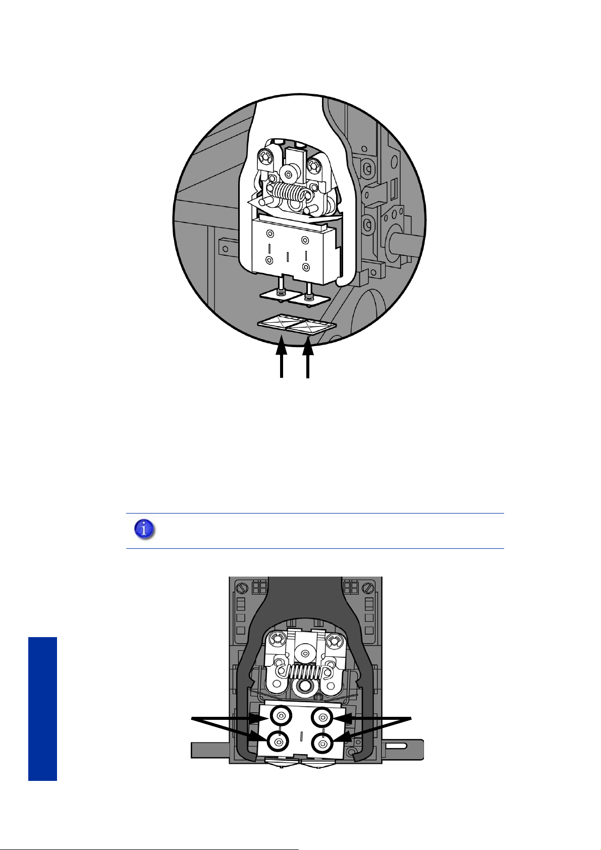
Figure 43 Install the tips
Tighten screws
Tighten screws
Maintenance
3. Use needle nose pliers to grasp the stainless steel shield of the tip.
4. Pull the tip shield toward you, then lift up to install the tip.
5. Push the tip toward the back of the printer once it is all the way up against the heater block.
6. Verify the tip is fully inserted into the heater block and that the stainless steel shield is
aligned. See Figure 44.
7. Use 7/64 T-Handle Allen wrench to firmly tighten the heater block clamp screws. See
Figure 44.
NOTE: Make sure the tip remains all the way up against the heater block as
you tighten the screws.
Figure 44 Tighten heater block clamp screws.
44
8. Repeat steps 3 through 7 for the other tip if necessary.
Page 49

9. Replace head cover and close the printer door.
NOTE: If the head cover is not replaced the printer may not function properly.
10. The printer will display Tip Maintenance - T i ps Replaced? - press Yes to begin material
load.
a. The printer will display Load Model - Replace Both Carriers
(flashing).
• If you want to replace a material carrier, do so now.
• If you do NOT want to change a material carrier, you must unlatch and latch
the carriers to continue (Push the carrier forward to unlatch, then push it
forward again to latch). Because the material ‘unloaded’ during the tip
replacement, the printer is in the material replacement mode. You must
unlatch and then latch the carriers to continue. If there is a delay in the
unlatch/latch process, the printer will display Both Carriers Not Replaced Or
Invalid. Select Retry, then unlatch and latch the carriers.
b. The printer will now begin to load material.
c. After material loading is complete the printer will display Tip
Calibration - Install Modeling Base And Build Calibration Part.
Tip calibration:
Tip replacement requires Tip Calibration.
1. Select Start Part (flashing) - the printer will run two calibration parts.
• The printer will automatically build a Z Calibration part, measure the part and
• The printer will then automatically build an XY Calibration part (approximately 10
2. When the XY Calibration part is complete the printer will display Remove Part and Select
XY Adjustment - X:0, Y:0
3. Remove the XY tip calibration part from the printer.
4. Inspect the part and calibrate the X and Y axis. See Figure 45.
a. Use the magnifier from the Startup kit to view the support road
b. Identify the location on the +X or –X side of the part where the
c. Read the number closest to this location. This is the required X
d. Select Increment or Decrement to input the X offset adjustment -
NOTE: Make sure a NEW modeling base is installed before starting
calibration. Calibration results will be incorrect if a NEW modeling base is not
used.
calibrate the Z Axis for tip depth and tip level (approximately 5 minutes). The Z
calibration is automatic.
minutes). You must inspect the XY Calibration part and calibrate the X and Y axis for
tip offset:
(shown in red).
support road is best centered within the model boundaries
(shown in blue).
Tip Offset adjustment. If the number is on the -X side, a negative
offset is required.
the value will change in the upper display window (by default,
the printer will be ready to accept the X value).
Maintenance
45
Page 50

e. When you are satisfied with your X offset value, Select Y and
repeat steps A- D to identify and input the required Y Tip Offset
adjustment.
Figure 45 Example XY Tip Offset Part.
This example requires an adjustment of X = + 2, Y = - 4
Maintenance
5. Select Done after you have input the X and Y offsets. The printer will return to Maintenance.
Run the XY calibration a second time to be sure the values changed the offset properly.
6. When finished, press Done until back at Idle.
46
Page 51

Chamber light bar replacement
1. Power down the printer.
2. Locate the wiring harness leading away from the top of the light bar.
3. Disconnect the light bar from the wiring harness by squeezing the wiring harness clip while
pulling down.
4. Remove the light bar by removing the three attachment screws (top, middle, bottom) - use
the 7/64 T-handle wrench supplied in the startup kit.
5. Install a replacement light bar with the three attachment screws - do not overtighten the
screws.
6. Re-attach the wiring harness lead.
Figure 46 Chamber light bar locations
47
Maintenance
Page 52

Troubleshooting
Troubleshooting
Troubleshooting
“Anomalous behavior” disclaimer:
In the presence of unusual electromagnet phenomena, such as strong
electromagnetic fields or severe electrical disturbances, the printer might
behave strangely, or even stop working. In this case, turn off the printer, wait
until the electromagnetic environment has returned to normal and then turn it on
again. If you still experience problems, call HP support.
Problem Recommendation
No power 1. Verify power cord is securely plugged in.
2. Verify that the circuit breaker (at rear of printer) and the power
switch (on left side panel of printer) are both in the ON position.
3. Verify AC power is present at wall outlet.
Material not extruding Material may be clogged in tip see “Clogged tip” on page52.
Purge material
accumulating on part.
No text displayed on
Display Panel
Cannot communicate with
printer through network or
crossover cable
Error code displayed on
display panel
Build Error Partial or bad part file sent to printer. Check STL file in CAD software
Check condition of tip wipe assembly. Replace if worn. See “Tip wipe
assembly” on page35
Cycle power. see “Cycling power” on page50.
1. Make sure network cables are connected - at the printer, at the PC,
or where cables connect to network hubs.
2. Re-configure network settings.
3. If using a static network address, verify that the IP address entered
in HP Designjet 3D Software Solution matches the IP address
entered in the printer.
4. Your network configuration may have changed. Contact your Net-
work Administrator.
Contact Technical Support. For more information, refer to“Fault
determination codes” on page50
for errors; reprocess STL in HP Designjet 3D Software Solution and redownload to printer.
48
Page 53

Error message on display
panel
Can’t Find Home – Check
Modeling Base
Recommendation
1. Verify a modeling base is inserted.
2. Modeling base may be used or defective – replace.
Material Error
Filament error
Material Error
Filament blocked
Material Error
Carrier invalid
Material Error
Filament broken
Load Error
Filament blocked
Load Error
Purge failed
Unload Error
Unload failed
Model/Support Jam
in head
clear before resuming
Pausing 1. Press Resume.
1. Remove the carrier and verify material is coming out of the material
guide.
2. Verify material pulls freely from the carrier.
3. Verify the material tubes are free of material.
4. Reload material.
1. Remove carrier and verify material pulls freely from carrier.
2. Verify the material tubes are free of material.
3. If the path is not obstructed, clean debris from Filament Present
Switch. See “Remove debris from the Filament Present switch” on
page40
4. Reload material.
1. Remove carrier and verify it is not empty.
2. Replace material spool.
3. Reload material.
1. Remove the carrier and verify material is coming out of the material
guide.
2. Verify material pulls freely from the carrier.
3. Verify the material tubes are free of material.
4. Reload material.
1. Remove the carrier and verify material is coming out of the material
guide.
2. Verify the material pulls freely from the carrier.
3. Verify the material tubes are free of material.
4. If the path is not obstructed, clean debris from Filament Present
Switch. See “Remove debris from the Filament Present switch” on
page40
5. Reload material.
1. Remove the carrier and verify material is coming out of the material
guide.
2. Verify the material pulls freely from the carrier.
3. Verify the material tubes are free of material.
4. Check for and clear any excess material build up around the tips.
Remove the carrier and verify the material tubes are free of material.
See “Material Jam” on page53.
2. Unload the material carriers and reinstall.
Troubleshooting
NOTE: Certain Filament related error messages will allow you to enter
maintenance mode after a 30 second timeout.
49
Page 54

Fault determination codes
Troubleshooting
Exporting printer configuration (.cfg) file
Exporting configuration file from printer:
If a fault occurs which would prevent the printer from executing an operator request, the printer
will begin to shut down and cool. The panel will display an error code. An error-code list (with
the filename “error.txt”) can be found on the DVD-ROM for the printer firmware. (Because this list
may change with each new software version, be sure to check the error.txt attachment when you
install new firmware upgrades.)
After the printer has finished cooling, the only option displayed is Continue. Press Continue and
the printer will reboot and try to return to normal operation. If pressing Continue does not
eliminate the error, power should be cycled (see “Cycling power” on page50.); wait 60
seconds before switching power on again. In most cases you will be able to continue operation.
However, if the printer continues to shut down and display the same error, contact technical
support.
If your printer is receiving fault determination codes, you may need to export a configuration
(.cfg) file from your printer to send to Customer Care.
1. Open HP Designjet 3D Software Solution from your workstation.
2. Click on the Printer Services tab.
3. Click on the Export Configuration button.
4. Browse to the directory where you wish to save the configuration file.
5. Click on the Save button.
6. Close HP Designjet 3D Software Solution.
Cycling power
1. Turn the power switch to the OFF position. The display will show Shutting Down.
2. After the printer has cooled down enough to shut down, the display will go blank.
3. When the display is blank and the printer has shut down, turn the circuit breaker to the OFF
position.
4. Once the circuit breaker has been turned to the OFF position, wait 60 seconds and turn the
circuit breaker back to the ON position.
5. Turn the power switch to the ON position. The printer display will show that it is starting up.
Once the display shows Idle or Read y to Pr int, you can send a file to the printer to be printed.
50
Page 55

Diagnosing loss of extrusion
Occasionally, the printer’s head may experience loss of extrusion. This will be evident by
observing one of the following:
• The head is moving with no material coming out of either tip
• The height of the model and support materials are not equal
• Sagging structures due to lack of support materials
GLOVES: The head area is hot. Use gloves when working in this area of
printer.
1. From the display panel press Cancel and remove parts from the printer.
2. Insert a new modeling base.
3. From Idle, press Maintenance
4. Press Machine.
5. Press Head. The head will move to the center of the chamber and the Z platform will
change position. The display will read: Model Drive Motor Stopped
6. Determine if there is a model material extrusion problem by pressing Forward (command
will be available after head reaches operating temperature). Watch the model tip (right tip)
for any extrusion (material purge).
Troubleshooting
NOTE: You may need to wait up to 30 seconds before extrusion will begin as
the tip may need to reach operating temperature.
7. Press Stop to stop the extrusion.
8. If material did NOT flow from the model tip, see “Recovering from loss of extrusion” on
page55. If material steadily flowed from the model tip, the model tip is functioning
properly.
9. Test the support material tip by choosing: Select Drive.
10. Determine if there is a support material extrusion problem by pressing Forward. Watch the
support tip (left tip) for any extrusion (material purge).
11 . Press Stop to stop the extrusion.
12 . If material did NOT flow from the support tip, see “Recovering from loss of extrusion” on
page55. If material steadily flowed from the support tip, the support tip is functioning
properly.
13 . Return the printer to the Maintenance state - Press Done, then press Yes when the printer
displays Is Material Loaded?
14 . Press Done until back at Idle.
51
Page 56

Clogged tip
Press tabs in to remove
head cover
Head Cover
Troubleshooting
Occasionally, a tip may clog with material. This will often result in a loss of extrusion (LOE). A
clogged tip will prohibit material load and part building.
1. Remove the head cover by pressing the tabs in and pulling away from the head. See Figure
47.
GLOVES: The head area is hot. Use leather gloves when working in this area
of printer.
Figure 47 Remove the head cover
2. Inspect to of tips for material build up. If there is excess material build up see “Recovering
from loss of extrusion” on page55. If there is no excess material build up close the
chamber door and continue.
3. From the display panel press Maintenance.
4. Press Machine. The printer will calibrate which will take approximately 3 minutes.
5. Press Head. The head will heat up to operating temperature which will take approximately
3 minutes.
6. Press Select Drive and choose the drive that may have the clogged tip.
7. Press Forward, the drive wheel will turn the selected drive forward.
8. Press Blower Off, this will turn the head cooling fan off for 10 seconds, allowing the tip to
heat up beyond operating temperature. If material starts to extrude the tip is no longer
clogged. If material does not extrude see “Recovering from loss of extrusion” on page55
9. Press Done.
10. Replace head cover.
NOTE: If the head cover is not replaced the printer may not function properly.
11 . Display will ask Which Materials Loaded? Press Both.
12 . Press Done until back to Idle.
52
Page 57

Material Jam
Press tabs in to remove
head cover
Head Cover
Occasionally, material may become jammed in the head. The printer will notify you of a
material jam through a message shown on the display panel. If a material jam is detected,
follow these steps to clear the jam.
1. From the display panel, press Continue.
2. Press Maintenance.
3. Press Machine.
4. Press Head.
5. Once in head maintenance mode, remove the head cover by pressing the tabs in and
pulling away from the head. See Figure 48.
Figure 48 Remove the head cover
Troubleshooting
GLOVES: The head area is hot. Use leather gloves when working in this area
of printer.
6. Inspect tip inlets for material build up see Figure 49. If there is excess material build up see
“Recovering from loss of extrusion” on page55. If there is no excess material build up
close the chamber door and continue.
53
Page 58
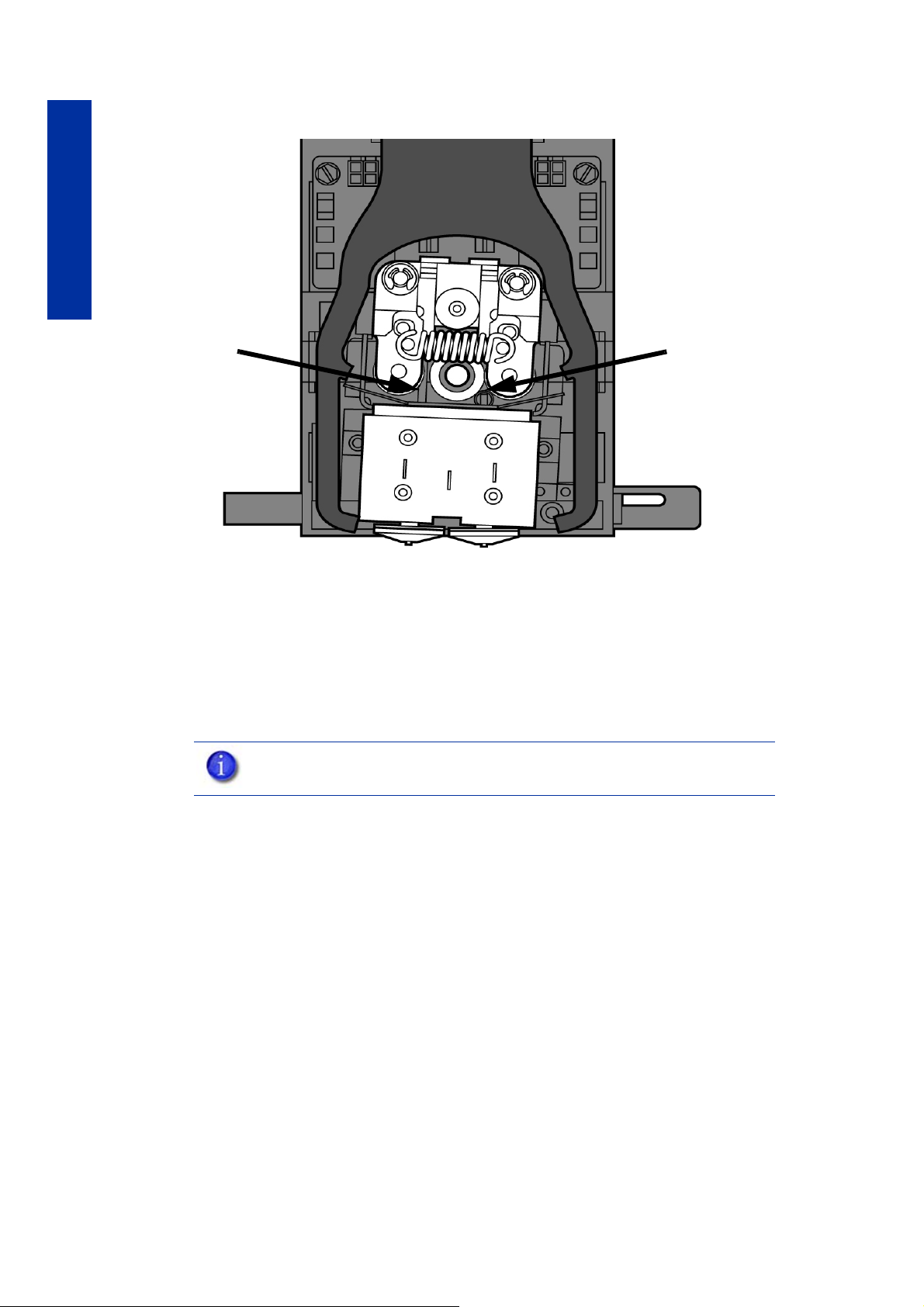
Troubleshooting
Model tip inlet
Support tip inlet
Figure 49 Tip inlet locations
7. Press Select Drive and choose the drive that may have the clogged tip.
8. Press Forward, the drive wheel will turn the selected drive forward.
9. Press Blower Off, this will turn the head cooling fan off for 10 seconds, allowing the tip to
heat up beyond operating temperature. If material starts to extrude the tip is no longer
clogged. If material does not extrude see “Recovering from loss of extrusion” on page55.
If material extrudes, you can continue building your part.
10. Replace head cover.
NOTE: If the head cover is not replaced the printer may not function properly.
11 . Press Done.
12 . Display will ask Which Materials Loaded? Press Both.
13 . Press Done until back to Pause screen.
14 . Press Resume to continue building the part.
54
Page 59
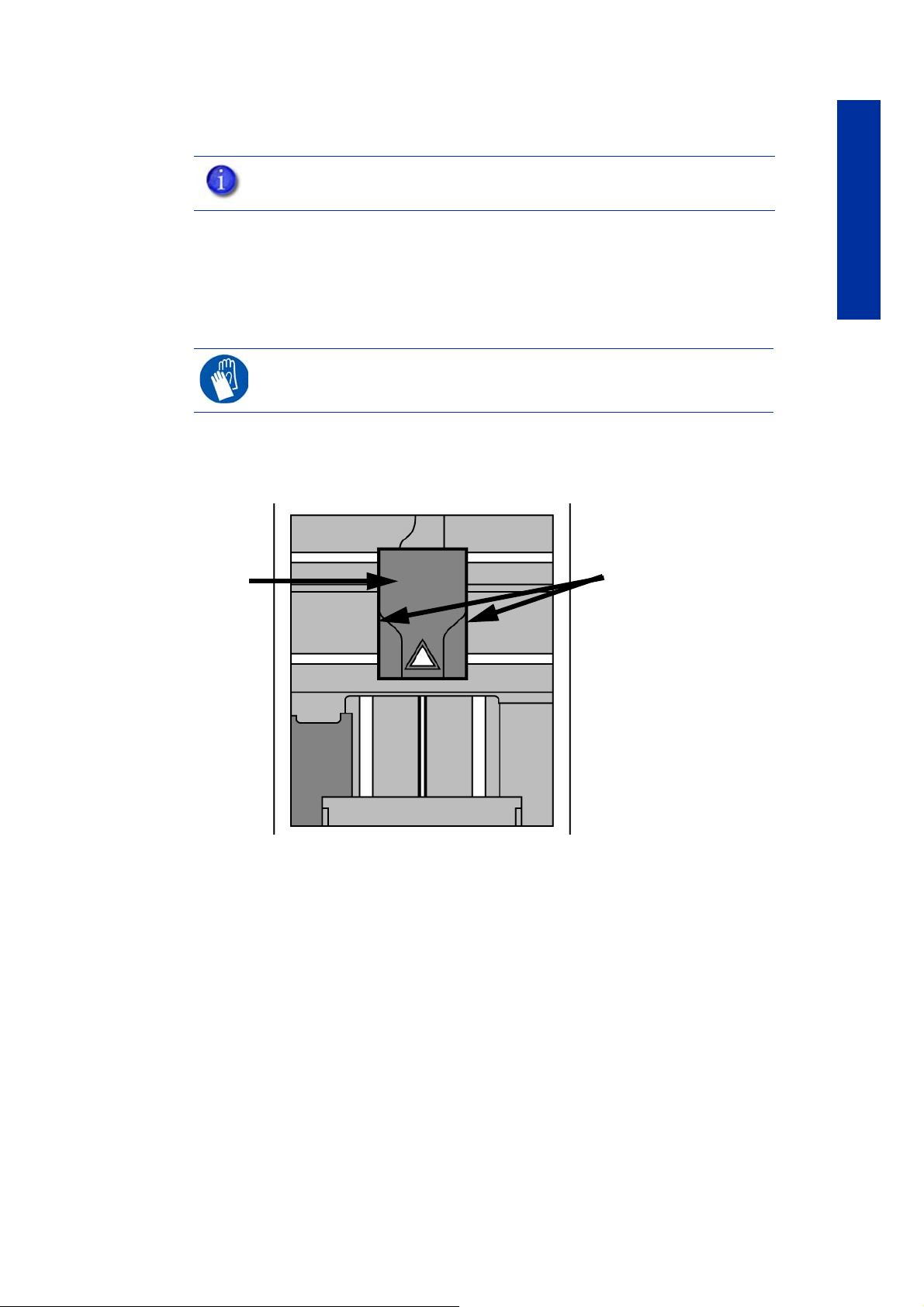
Recovering from loss of extrusion
Press tabs in to remove
head cover
Head Cover
NOTE: It is recommended that you read and understand this entire procedure
before performing any of the work.
1. Enter Head Maintenance mode.
a. From Idle, press Maintenance.
b. Press Machine.
c. Press Head. The head will heat up to operating temperature
which will take approximately 3 minutes.
GLOVES: The head area is hot. Use leather gloves when working in this area
of printer.
2. Remove the head cover by pressing the tabs in and pulling away from the head. See Figure
50.
Figure 50 Remove the head cover
Troubleshooting
3. Place the toggle bar in neutral position (bar will extend equally from both sides of head).
This can be done manually - push on the extended bar end. See Fi gu re 51.
55
Page 60

Troubleshooting
Support side
idler wheel
Model side idler
wheel
Toggle spring
Heater block
Drive wheel
Toggle bar
Figure 51 Head Components
Figure 52 Toggle bar in neutral position
4. Remove any excess material found around the head area.
NOTE: Material fed to the tip can sometimes jam causing a build-up of
material under the head cover.
a. Clean out as much of the material as possible using needle nose
pliers, a probe, or equivalent tool.
CAUTION: The end of the tip where the material enters is called the extrusion
tube. Extrusion tubes are fragile. Use care when working in this area so as to
avoid damage to the tubes.
56
Page 61

b. For easier access to areas that may need to be cleaned, move
Position toggle
bar to same
side of head as
T-Handle.
Toggle spring
post
Idler wheel post
the material idler wheels out of the way (there is one idler wheel
for support material and one for model material, see Fi gu re 51.)
NOTE: Move only one idler wheel assembly at a time. Finish cleaning around
the moved wheel and restore it to its normal position before moving the other
idler wheel. Having both wheels out of position simultaneously could stretch the
spring.
i. Place a 7/64 T-Handle Allen wrench between the toggle spring post and
the idler wheel post as illustrated in Figure 53. (model side shown).
ii. Position toggle bar to the same side of the head as the T-Handle allen
wrench. See Figure 53. (model side shown).
Figure 53 Create access space for cleaning - model side shown
Troubleshooting
iii. Move idler wheel assembly by pushing with 7/64 inch T-Handle Allen
wrench against spring tension. Insert a 1/8 T-handled Allen wrench (from
startup kit) into the fixture hole. See Figure 54.
57
Page 62
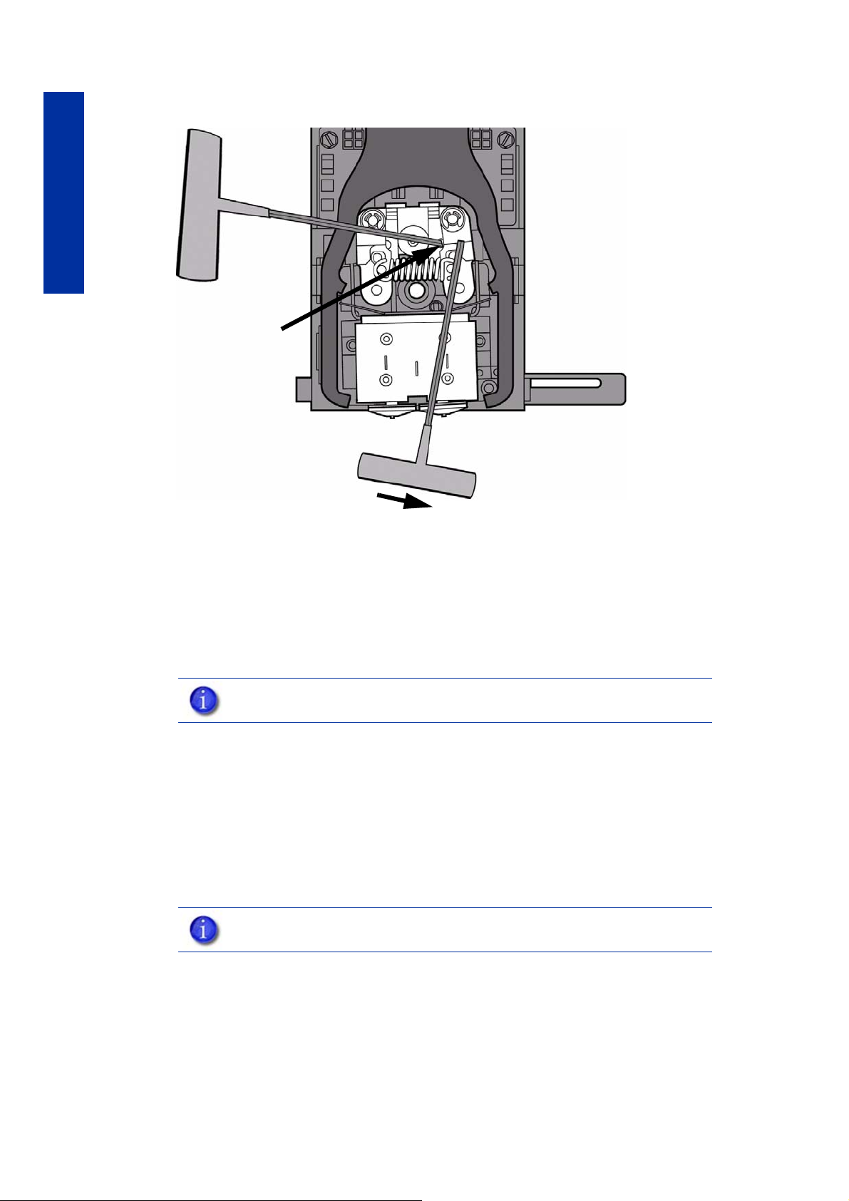
Troubleshooting
Insert 1/8 inch
T-Handle into
fixture hole.
Figure 54 Holding access space open - model side shown
iv. Ease pressure on the 7/64 T-Handle Allen wrench to carefully return the
leveraged idler wheel back toward its original position - until the idler
assembly is resting against the 1/8 T-Handle Allen wrench.
v. Remove the 7/64 T-Handle Allen wrench.
c. Cut the material above the idler wheel using a cutters.
d. Clean the area that is now accessible using a needle nose
pliers, a probe or equivalent tool.
NOTE: Make sure that all loose material is removed from the affected area.
e. Reposition the 7/64 T-Handle Allen wrench between the toggle
spring post and the idler wheel post.
f. Move idler wheel assembly by pushing with 7/64 inch T-Handle
Allen wrench against spring tension and remove the 1/8 Thandled Allen wrench.
g. Remove the 7/64 T-Handle Allen wrench.
5. Repeat for the opposite side as needed.
6. Replace head cover.
NOTE: If the head cover is not replaced the printer may not function properly.
7. Press Done on the display panel.
58
8. Display will ask Which Materials Loaded? Press Model if only model material is loaded,
9. Display will ask you to remove the carrier of the materials that are not loaded. Remove the
10. Press Done until back at Idle.
11 . Reload the material that is not loaded.
press Support if only support material is loaded or press Both if both model and support
material are still loaded. Press None if neither are loaded.
carrier and cut the excess material.
Page 63

Support
Introduction
HP Customer Care offers award-winning support to ensure you get the most from your HP
Designjet 3D printer, providing comprehensive, proven support expertise and new technologies
to give you unique end-to-end support. Services include setup and installation, troubleshooting
tools, warranty upgrades, repair and exchange services, phone and Web support, software
updates and self-maintenance services. To find out more about HP Customer Care, please visit us
at:
http://www.hp.com/go/graphic-arts/
or call us on the telephone, See “Contact HP Support” on page60.
To register your warranty:
Support
http://register.hp.com/
HP Professional Services
Knowledge Center
Enjoy a world of dedicated services and resources to ensure you always get the best
performance from you HP Designjet 3D products and solutions.
Join the HP community at the Knowledge Center, your large-format printing community, for 24x7
access to:
• Multimedia tutorials.
• Step-by-step how-to guides.
• Downloads - the latest printer firmware, drivers, software, etc.
• Technical support - online troubleshooting, customer care contacts and more.
• Workflows and detailed advice for completing various printing tasks from particular
software applications.
• Forums for direct contact with the experts, both HP and your colleagues.
• Warranty tracking online, for your peace of mind.
• Latest product information - printers, supplies, accessories, software, etc.
• Supplies Center for all you need to know about material.
The Knowledge Center can be found at the following locations, depending on your printer:
• http://www.hp.com/go/3dprinter/knowledgecenter/
By customizing your registration for the products you have purchased and your type of business,
and by setting your communication preferences, you decide the information you need.
59
Page 64

HP Care Packs and Warranty Extensions
HP Care Packs and Warranty Extensions allow you to extend your printer’s warranty beyond the
standard period.
They include remote support. On-site service is also provided if necessary, with two alternative
response-time options.
• Next business day.
• Same business day, within four hours (may not be available in all countries).
For more information on HP Care Packs, please visit http://www.hp.com/go/printservices/.
HP Installation
The HP Installation service unpacks, sets up and connects the printer for you.
Support
This is one of the HP Care Pack services; for more information, please visit http://www.hp.com/
go/printservices/.
Contact HP Support
HP Support is available to you by telephone. What to do before you call:
• Review the troubleshooting suggestions in this guide.
• If you call one of the Hewlett-Packard offices, please have the following information
available to help us answer your questions more quickly:
• The printer you are using (the product number and the serial number, found on the label at
the back of the printer).
• If there is an error code on the display panel, note it down; See “Fault determination
codes” on page50.
• The computer you are using.
• Any special equipment or software you are using (for example, networks, switch-boxes,
modems or special software drivers.
• The network cable you are using (by part number) and where you purchased it.
• The software name and version you are currently using.
• If possible, download the configuration file (.CFG) from the printer; you may be asked to
email it to the support center helping you. See “Exporting printer configuration (.cfg) file”
on page50.
Telephone number
Your HP Support telephone number is available on the Web: please visit
http://welcome.hp.com/country/us/en/wwcontact_us.html
60
Page 65
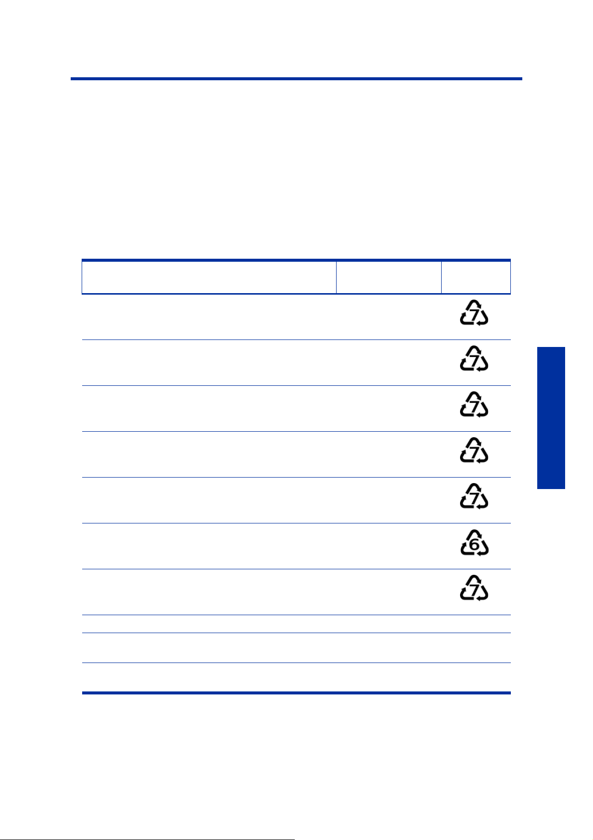
Recycling
Recycle all materials per your local recycling guidelines.
Figure 55 Recycling Codes
System Component Materials
X (2) and Y (4) guide rod restraints (orange) ABS
Model material guide (red, both halves) ABS
Support material guide (black, both halves) ACETAL
Material retaining clip (blue) ABS
Material Carrier (clear top, black bottom and bottom
cover. Latches, hinge pin and electronics not included)
Material Spool & lid (gray) PS - HI
PC
Recycling
Code
Recycling
Modeling bases ABS
EEproms Electronics
Desiccants can be recycled per your local recycling
guidelines
All packaging materials can be recycled per your local
recycling guidelines.
Follow your local recycling guidelines when recycling electronic components.
61
Page 66
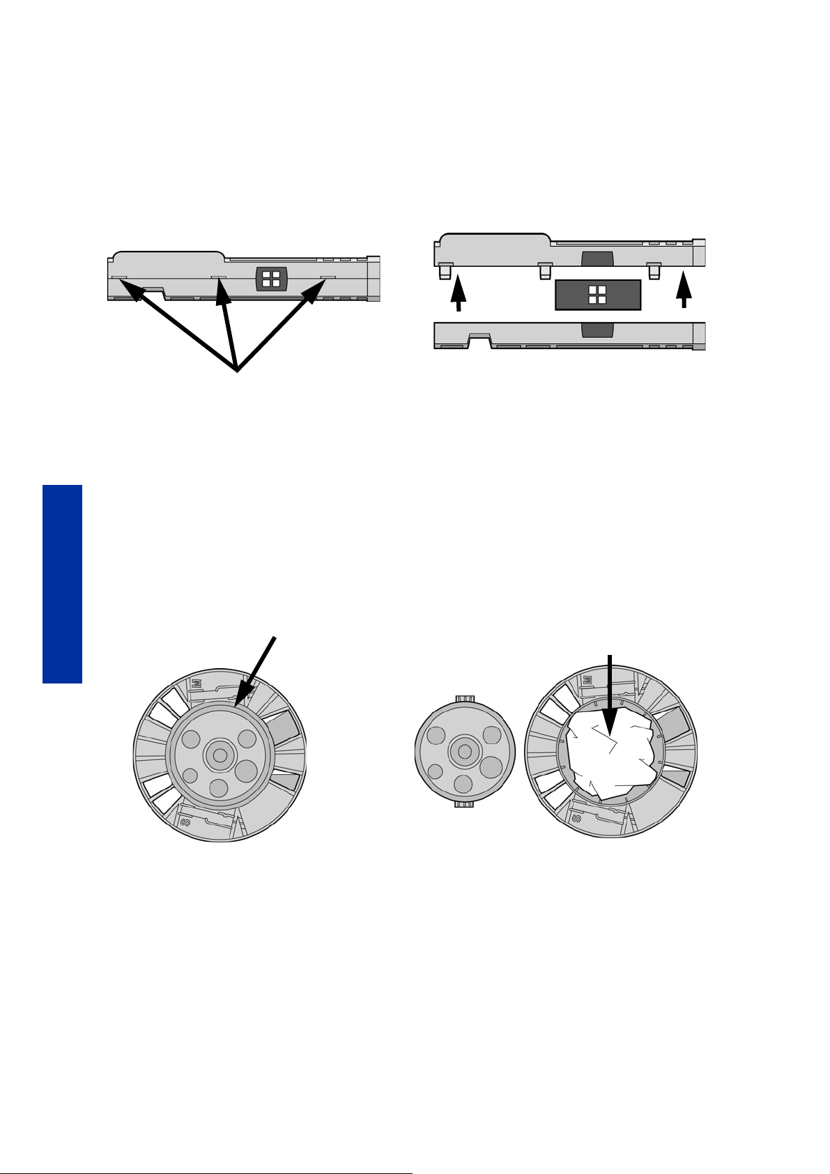
Removing the EEproms from the material guides
Pry apart with a small standard screwdriver
Pry apart with a standard
screwdriver
Remove the desiccant and
recycle. Recycle the
material spool.
1. Open the model and support material carriers and remove the material guides.
2. With a small standard screwdriver, pry the two material guide halves apart. See Figure 56.
Figure 56 Pry the model material guide apart
3. Recycle the EEPROM per your local electronics recycling guidelines.
4. Recycle the material guides per your local guidelines. See Figure 55.
Removing the desiccant from the material spool
1. Remove the excess material from the material spool.
Recycling
2. Use a standard screwdriver to pry the desiccant cover open. See Figure 57.
Figure 57 Removing the desiccant
3. Remove the desiccant and recycle per your local guidelines.
4. Recycle the material spool per your local guidelines.
62
Page 67

Printer Specifications
The information in this section is applicable to both HP Designjet 3D and HP Designjet Color 3D
printers.
Physical specifications
Height 30 in (762 mm)
Width 26 in (660 mm)
Depth 26 in (660 mm)
Weight 130 lbs (59 kg)
Material bay height 6 in (153 mm)
Material bay width 26 in (660 mm)
Material bay depth 26 in (660 mm)
Material bay weight 37 lbs (17 kg)
Facility specifications
Installation location Stable flat surface capable of holding 220 lbs (100 kg), with a height
clearance of 36 - 40 in (90 - 100 cm).
Note - if using additional material bay:
Stable flat surface capable of holding 260 lbs (120 kg), with a height
clearance of 46 - 50 in (117 - 127 cm).
Power Requirements 100–240VAC ~ 12 - 7A 50/60Hz 1200W dedicated circuit within 80 in (2
m)
Do not use an extension cord or a power strip, using these can possibly
cause intermittent power issues.)
Air Circulation 4.5 in (115 mm) minimum space behind printer for air circulation.
6 in (153 mm) minimum space around printer for air circulation.
Network Connection Ethernet 10/100 Base T within 14 ft (4m).
Printer Specifications
63
Page 68

Workstation specifications
Operating System Microsoft Windows XP, Microsoft Windows Vista or Microsoft Windows 7
Processor Minimum: 2.4 GHz
Faster processors will shorten job processing times
RAM Minimum: 1GB (2GB for Windows Vista or Windows 7)
Recommended: 2GB (3GB for Windows Vista or Windows 7)
Hard Disk Installation: 90MB
Monitor graphics
resolution
Video Card Required: OpenGL compliant accelerated graphics card
Minimum: 1024x768
Recommended: 1280x1024 (wide screen acceptable)
Recommended: Hardware support for OpenGL
Recommended 128MB graphics card memory
Power specifications
Source (nominal) 100–240VAC ~ 12 - 7A 50/60Hz 1200W
Do not use an extension cord or a power strip, using these can possibly
cause intermittent power issues.
Ecological specifications
For the up-to-date ecological specifications of your printer, please go to http://www.hp.com/
and search for “ecological specifications”.
Environmental specifications
Temperature range
Relative humidity range 30 to 70 percent, non condensing
.
59◦F to 86◦F (15◦C to 30◦C)
Printer Specifications
Acoustic specifications
Heat emission 2550 BTU/hr typical
Idle sound pressure at bystander
Operating sound pressure at
bystander
55 dBA
62 dBA
64
Page 69

Supplemental Information
HP Designjet 3D and HP Designjet Color 3D Printer series
Hewlett Packard Limited Warranty Statement
HP Product Limited Warranty Period
HP Designjet 3D Printer
HP Designjet Color 3D Printer
HP Designjet 3D Material Bay
HP Designjet 3D ABS Material
HP Designjet 3D Software Solution 90 days
1 year
A. Extent of HP Limited Warranty
1. HP warrants to you, end-user customer, that the HP hardware products, accessories and
supplies specified above will be free from defects in materials and workmanship under
normal usage during the Limited Warranty Period specified above. The Limited Warranty
Period starts on the date of purchase by you. Your dated sales or delivery receipt, showing
the date of purchase of the product, is your proof of purchase date. You may be required to
provide proof of purchase as a condition of receiving warranty service.
2. For software products, HP’s Limited Warranty applies only to a failure to execute
programming instructions for the Limited Warranty Period specified above, due to defects in
material, and workmanship when properly installed and used on the device designated by
HP. HP further warrants that HP owned standard software will substantially conform to
specifications. HP does not warrant that software will operate in hardware and software
combinations selected by you, or meet requirements specified by you.
3. HP does not warrant that the operation of any product will be uninterrupted or error free.
4. HP’s Limited Warranty covers only those defects that arise as a result of normal use of the
HP products, and does not cover any other problems, including those that arise as result of:
a. Improper or inadequate maintenance or calibration;
b. Accessories, software, interfacing, paper, parts, ink or supplies
not provided or supported by HP; a
c. Operation outside the product’s specifications;
d. Improper site preparation or maintenance; or
e. Unauthorized modification or misuse.
Routine printer maintenance operations in the HP Printer, such as cleaning and preventive
maintenance services (including parts contained in any preventive maintenance kit and HP
service engineer visits), are not covered by HP’s Limited Warranty.
l
65
Supplemental Information
Page 70

5. For HP Printer, the use of a refilled or non-original HP consumable product (ink, printhead
or ink cartridge) does not affect either HP’s Limited Warranty to you or any HP support
contract with you. However, if printer failure or damage is attributable to the use of a nonHP consumable product, HP will charge its standard time and materials charges to service
the printer for the particular failure or damage.
6. If HP or a HP authorized service provider receives, during the applicable warranty period,
notice of a defect in any product covered by this HP’s Limited Warranty, HP shall, at its
option, either repair or replace the defective product which proves to be defective.
7. Customer self-repair warranty service. HP products are designed with many
Customer Self Repair (CSR) parts to minimize repair time and allow for greater flexibility in
performing defective parts replacement. If during the diagnosis period, HP identifies that
the repair can be accomplished by the use of a CSR part, HP will ship that part directly to
you for replacement. There are two categories of CSR parts: 1) Parts for which customer self
repair is mandatory. If you request HP to replace these parts, you will be charged for the
travel and labor costs of this service. 2) Parts for which customer self repair is optional.
These parts are also designed for Customer Self Repair. If, however, you require that HP
replace them for you, this may be done at no additional charge under the type of warranty
service designated for your product.
Based on availability and where geography permits, CSR parts will be shipped for next
business day delivery. Same-day or four-hour delivery may be offered at an additional
charge where geography permits. If assistance is required, you can call the HP Technical
Support Center and a technician will help you over the phone. HP specifies in the materials
shipped with a replacement CSR part whether a defective part must be returned to HP. In
cases where it is required to return the defective part to HP, you must ship the defective part
back to HP within a defined period of time, normally five (5) business days. The defective
part must be returned with the associated documentation in the provided shipping material.
Failure to return the defective part may result in HP billing you for the replacement. With a
customer self repair, HP will pay all shipping and part return costs and determine the
courier/carrier to be used.
Supplemental Information
8. Should HP elect to replace or repair the defective product or part onsite, such products will
be serviced at the end-user customer's facility at no charge only within designated local
service travel areas. Outside designated local service travel areas, warranty services will
be performed at the end-user customer's facility only upon prior agreement; you may be
required to pay travel expenses and other applicable expenses for such services. Contact
your local HP authorized service provider for details on local travel areas.
9. You will make all reasonable efforts to support and cooperate with HP or a HP authorized
service provider in resolving the problem remotely, for example, starting and executing self
tests or diagnostic programs, providing all necessary information, or performing basic
remedial activities upon HP’s or a HP authorized service provider request.
10. If HP is unable to repair or replace, as applicable, a defective product which is covered by
this Limited Warranty, HP shall, within a reasonable time after being notified of the defect,
refund the residual value of the product. The residual value will be the purchase price paid
to HP or HP Authorized Reseller minus depreciation and amortization.
11 . HP shall have no obligation to replace or refund until you return the defective components,
parts, supplies or hardware product to HP, including its associated documentation. All
components, parts, supplies or hardware products, removed under this Limited Warranty
become the property of HP. Notwithstanding the above mentioned, HP may waive the
requirement for you to return the defective product.
12 . Unless otherwise stated, and to the extent permitted by local law, HP products may be
manufactured using new materials or new and used materials equivalent to new in
performance and reliability. HP may repair or replace products (i) with equivalent products
to the products being repaired or replaced but which may have been subject to prior use;
or (ii) with an equivalent product to an original product that has been discontinued.
66
Page 71

13 . This Limited Warranty is valid in any country/region where HP or its authorized providers
offer warranty services and HP has marketed the HP product covered by this Limited
Warranty. However, warranty service availability and response time may vary from
country/region to country/region. HP will not alter form, fit, or function of the product to
make it operate in a country for which it was never intended to function for legal or
regulatory reasons. This HP Limited Warranty is subject to all applicable laws and
regulations including US and other national export and import laws and regulations.
14 . Contracts for additional services may be available for any authorized HP service facility
where the listed HP product is distributed by HP or an authorized importer.
15. You are responsible for the security of your proprietary and confidential information and for
maintaining a procedure external to the printer for reconstruction of lost, or altered files,
data, or programs. HP IS NOT RESPONSIBLE FOR DAMAGE TO OR LOSS OF ANY FILES,
STORED BY YOU ON THE PRINTER'S HARD DISK OR OTHER STORAGE DEVICES. HP IS
NOT RESPONSIBLE FOR THE RECOVERY OF LOST FILES OR DATA.
B. Limitation of warranty
TO THE EXTENT ALLOWED BY LOCAL LAW, NEITHER HP NOR ITS THIRD PARTY SUPPLIERS
MAKE ANY OTHER WARRANTY OR CONDITION OF ANY KIND, WHETHER EXPRESS OR
IMPLIED, AND SPECIFICALLY DISCLAIM THE IMPLIED WARRANTIES OR CONDITIONS OF
MERCHANTABILITY, SATISFACTORY QUALITY, AND FITNESS FOR A PARTICULAR PURPOSE.
C. Limitations of liability
TO THE EXTENT ALLOWED BY LOCAL LAW, THE REMEDIES IN THIS LIMITED WARRANTY ARE
YOUR SOLE AND EXCLUSIVE REMEDIES. EXCEPT AS INDICATED ABOVE, IN NO EVENT WILL
HP OR ITS THIRD PARTY SUPPLIERS BE LIABLE FOR LOST OF DATA, DIRECT, INDIRECT,
SPECIAL, INCIDENTAL, OR CONSEQUENTIAL DAMAGES (INCLUDING ANY LOSS OF
PROFITS OR SAVINGS), WHETHER BASED ON CONTRACT, TORT, OR ANY OTHER LEGAL
THEORY AND WHETHER ADVISED OF THE POSSIBILITY OF SUCH DAMAGES.
D. Local law
1. This Limited Warranty gives you specific legal rights. You may also have other rights which
2. To the extent that this Warranty Statement is inconsistent with local law, this Warranty
vary from state to state in the United States, from province to province in Canada, and from
country to country elsewhere in the world. You are advised to consult applicable state,
province, or national laws for full determination of your rights.
Statement shall be deemed modified to be consistent with such local law. THE WARRANTY
TERMS CONTAINED IN THIS LIMITED WARRANTY, EXCEPT TO THE EXTENT LAWFULLY
PERMITTED, DO NOT EXCLUDE, RESTRICT, OR MODIFY AND ARE IN ADDITION TO THE
MANDATORY STATUTORY RIGHTS APPLICABLE TO THE SALE OF THIS PRODUCT TO
YOU.
Rev. 05/09
67
Supplemental Information
Page 72

Declaration of conformity
according to ISO/IEC 17050-1 and EN 17050-1
Declaration of conformity number BCLAA-0903
Supplier’s name: Hewlett-Packard Company
Supplier’s address: Cami de Can Graells, 1-21
declares that the product
08174 Sant Cugat del Vallès
Barcelona, Spain
Product name and
model:
Regulatory Model
Number(1):
Product options: All
HP Designjet 3D printer series
HP Designjet Color 3D printer series
BCLAA-0903
conforms to the following product specifications
Safety: IEC 60950-1:2007 (2nd Edition) / EN 60950-1:2007
CAN/CSA-C22.2 No. 60950-1-07 / UL 60950-1:2007
EMC: EN 55022:2006 / CISPR 22:2005 Class A
EN 55024:1998 + A1:2001 + A2:2003
EN 61000-3-2:2006 / IEC 61000-3-2:2005
EN 61000-3-3:1995 + A1:2001 + A2:2006 / IEC 61000-3-3:1994 +
A1:2001
FCC Title 47 CFR, Part 15 Class A
The product herewith complies with the requirements of the Low-Voltage Directive 2006/95/EC
and the EMC Directive 2004/108/EEC, and carries the marking accordingly. In addition,
it complies with the WEEE Directive 2002/96/EC and RoHS Directive 2002/95/EC.
Supplemental Information
This device complies with part 15 of the FCC Rules. Operation is subject to the following two
conditions:
• This device may not cause harmful interference.
• This device must accept any interference received, including interference that may cause
undesired operation.
Additional information
The product is assigned a Regulatory Model Number which stays with the regulatory aspects of
the design. The Regulatory Model Number is the main product identifier in the regulatory
documentation and test reports; this number should not be confused with the marketing name or
the product numbers.
Local contacts for regulatory topics only
http://www.hp.com/go/certificates/
EMEA contact: Hewlett-Packard GmBH, HQ-TRE, Herrenberger Strasse 140, 71034 Böblingen,
Germany.
USA contact: Hewlett-Packard Company, Corporate Product Regulations Manager, 3000
Hanover Street, Palo Alto, CA 94304, USA. Phone: (650) 857 1501.
68
Page 73

Regulatory and Environmental Information
Regulatory Model Identification Number
For regulatory identification purposes, your product is assigned a Regulatory Model Number.
The Regulatory Model Number for your product is BCLAA-0903. This regulatory number should
not be confused with the marketing name (such as HP Designjet 3D printer) or product numbers
(such as Z####X, where Z and X are any single letter and # is any number).
EMC Class A Warning
WARNING: This is a Class A product. In a domestic environment this product
may cause radio interference in which case the user may be required to take
adequate measures.
FCC Statements (U.S.A.)
The U.S. Federal Communications Commission (in 47 cfr1 5.105) has specified that the following
notices be brought to the attention of users of this product.
This device complies with part 15 of the FCC rules. Operation is subject to the following two
conditions:(1) this device may not cause harmful interference, and (2) this device must accept any
interference received, including interference that may cause undesired operation.
Shielded cables: use of shielded data cables is required to comply with the Class A limits of
Part 15 of the FCC Rules.
Caution: Pursuant to Part 15.21 of the FCC Rules, any changes or modifications to this equipment
not expressly approved by the Hewlett-Packard Company may cause harmful interference and
void the FCC authorization to operate this equipment.
Note: This equipment has been tested and found to comply with the limits for a Class A digital
device, pursuant to Part 15 of the FCC Rules. These limits are designed to provide reasonable
protection against harmful interference in a commercial environment. This equipment generates,
uses and can radiate radio frequency energy and, if not installed and used in accordance with
the instructions, may cause harmful interference to radio communications. Operation of this
equipment in a residential area is likely to cause harmful interference, in which case the user will
be required to correct the interference at their own expense.
Canada Electromagnetic compatibility (EMC)
Normes de sécurité (Canada)
Le présent appareil numérique n’émet pas de bruits radioélectriques dépassant les limites
applicables aux appareils numériques de Classe A prescrites dans le réglement sur le
brouillage radioélectrique édicté par le Ministère des Communications du Canada.
DOC statement (Canada)
This digital apparatus does not exceed the Class A limits for radio noise emissions from digital
apparatus set out in the Radio Interference Regulations of the Canadian Department of
Communications.
69
Supplemental Information
Page 74
MSDS (Material Safety Data Sheet)
You can obtain current Material Safety Data Sheets for the material used in the printer by,
mailing a request to this address: Hewlett-Packard Customer Information Center, 19310
Pruneridge Avenue, Dept. MSDS, Cupertino, CA 95014, U.S.A.
There is also a Web page: http://www.hp.com/hpinfo/globalcitizenship/environment/
products/msds-specs.html
Disposal of waste equipment by users in private households in the European Union
This symbol on the product or on its packaging indicates that this product must not be disposed
of with your other household waste. Instead, it is your responsibility to dispose of your waste
equipment by handing it over to a designated collection point for the recycling of waste
electrical and electronic equipment. The separate collection and recycling of your waste
equipment at the time of disposal will help to conserve natural resources and ensure that it is
recycled in a manner that protects human health and the environment. For more information
about where you can drop off your waste equipment for recycling, please contact your local city
office, your household waste disposal service or the shop where you purchased the product.
Supplemental Information
Chemical Substances
HP is committed to providing our customers with information about the chemical substances in
our products as needed to comply with legal requirements such as REACH (Regulation EC No
1907/2006 of the European Parliament and the Council). A chemical information report for this
product can be found at:
http://www.hp.com/go/reach
Eco-Tips
HP is committed to helping customers reduce their environmental footprint. HP has provided the
Eco-Tips below to help you focus on ways to assess and reduce the impact of your printing
choices. In addition to specific features in this product, please visit the HP Eco Solutions website
for more information on HP’s environmental initiatives.
http://www.hp.com/hpinfo/globalcitizenship/environment/
Environmental product stewardship program
Hewlett-Packard is committed to providing quality products in an environmentally sound manner.
Design for recycling has been incorporated into this product. The number of materials has been
kept to a minimum while ensuring proper functionality and reliability. Dissimilar materials have
been designed to separate easily. Fasteners and other connections are easy to locate, access
and remove using common tools. High priority parts have been designed to access quickly for
efficient disassembly and repair. For more information, visit HP’s Commitment to the Environment
website at:
70
http://www.hp.com/hpinfo/globalcitizenship/environment/
Page 75

Recycling Program
HP offers an increasing number of product return and recycling programs in many countries/
regions, and partners with some of the largest electronics recycling centers throughout the world.
HP conserves resources by reselling some of its most popular products.
For more information regarding recycling of HP products, please visit:
http://www.hp.com/hpinfo/globalcitizenship/environment/recycle/
71
Supplemental Information
 Loading...