

Page 1
LASERJET PRO CP1020
COLOR PRINTER SERIES
Service Manual
Page 2

Copyright and License
Trademark Credits
© 2010 Copyright Hewlett-Packard
Development Company, L.P.
Reproduction, adaptation, or translation
without prior written permission is
prohibited, except as allowed under the
copyright laws.
The information contained herein is subject
to change without notice.
The only warranties for HP products and
services are set forth in the express warranty
statements accompanying such products and
services. Nothing herein should be
construed as constituting an additional
warranty. HP shall not be liable for technical
or editorial errors or omissions contained
herein.
Part number: CE913-90943
Edition 1, 10/2010
Microsoft®, Windows®, Windows® XP,
and Windows Vista® are U.S. registered
trademarks of Microsoft Corporation.
Page 3

Conventions used in this guide
TIP: Tips provide helpful hints or shortcuts.
NOTE: Notes provide important information to explain a concept or to complete a task.
CAUTION: Cautions indicate procedures that you should follow to avoid losing data or damaging
the product.
WARNING! Warnings alert you to specific procedures that you should follow to avoid personal
injury, catastrophic loss of data, or extensive damage to the product.
ENWW iii
Page 4

Table of contents
1 Removal and replacement ................................................................................................ 1
Introduction ............................................................................................................................. 2
Removal and replacement strategy ............................................................................................. 2
Electrostatic discharge .............................................................................................................. 3
Required tools .......................................................................................................................... 3
Service approach ..................................................................................................................... 4
Before performing service .......................................................................................... 4
After performing service ............................................................................................. 4
Post-service test ......................................................................................................... 4
Print-quality test .......................................................................................... 4
Parts removal order ................................................................................................... 5
Removal and replacement procedures ........................................................................................ 6
Replace the print cartridges ........................................................................................ 6
Replace the imaging drum .......................................................................................... 9
Input tray ............................................................................................................... 13
Secondary transfer roller .......................................................................................... 14
Separation pad assembly ......................................................................................... 15
Remove the separation pad assembly ......................................................... 15
Pickup roller ........................................................................................................... 16
Remove the pickup roller assembly ............................................................. 17
Covers ................................................................................................................... 18
Right cover assembly ................................................................................ 18
Remove the right cover assembly ................................................. 18
Left cover assembly ................................................................................... 19
Remove the left cover assembly ................................................... 19
Top door assembly ................................................................................... 20
Remove the top door assembly .................................................... 20
Rear top cover assembly ........................................................................... 22
Remove the rear top cover assembly ............................................ 22
Rear door assembly .................................................................................. 23
Remove the rear door assembly .................................................. 23
Rear lower cover assembly ........................................................................ 24
Remove the rear lower cover assembly ......................................... 24
Control panel .......................................................................................... 25
ENWW v
Page 5

Remove the control panel ........................................................... 25
Front door ............................................................................................... 27
Remove the front door ................................................................ 27
Main assemblies ..................................................................................................... 29
ITB assembly ............................................................................................ 29
Remove the ITB assembly ............................................................ 29
Fuser delivery assembly ............................................................................ 38
Remove the fuser delivery assembly ............................................. 39
Formatter PCA (base model) ...................................................................... 43
Remove the formatter PCA (base model) ....................................... 43
Formatter and wireless PCA (plus model) ..................................................... 44
Remove the formatter and wireless PCA (plus model) ..................... 44
Engine controller assembly ........................................................................ 46
Remove the engine controller assembly ........................................ 46
Low-voltage power supply assembly ........................................................... 49
Remove the low-voltage power supply assembly ............................ 49
2 Solve problems ............................................................................................................... 53
Solve problems checklist ......................................................................................................... 54
Step 1: Make sure that the product is set up correctly .................................................. 54
Step 2: Check the cabling or wireless connection (network models only) ........................ 54
Step 3: Check to see if any control-panel lights are lit .................................................. 54
Step 4: Check the paper .......................................................................................... 54
Step 5: Check the software ....................................................................................... 55
Step 6: Test print functionality ................................................................................... 55
Step 7: Check the supplies ....................................................................................... 55
Step 8: Try sending a print job from a computer ......................................................... 55
Troubleshooting process .......................................................................................................... 56
Determine the problem source ................................................................................... 56
Power subsystem ..................................................................................................... 57
Power-on checks ...................................................................................... 57
Tools for troubleshooting ......................................................................................................... 58
Component diagnostics ............................................................................................ 58
Engine diagnostics ................................................................................... 58
Engine test page ...................................................................................... 58
Diagrams ............................................................................................................... 59
Plug/jack locations ................................................................................... 59
Locations of connectors ............................................................................. 60
Locations of major components .................................................................. 61
General timing chart ................................................................................. 63
General circuit diagram ............................................................................ 64
Internal print-quality test pages .................................................................................. 65
Print quality troubleshooting page .............................................................. 65
vi ENWW
Page 6

Interpret the Print Quality Page .................................................... 65
Clean the paper path ............................................................................... 66
Print configuration page ............................................................................ 66
Print-quality troubleshooting tools .............................................................................. 67
Repetitive image defects ruler .................................................................... 67
Calibrate the product ................................................................................ 67
Interpret control panel light patterns ........................................................................... 68
Status alert messages ............................................................................................... 71
Clear jams ............................................................................................................................ 77
Prevent paper jams .................................................................................................. 77
Jam locations .......................................................................................................... 78
Clear jams from the input tray ................................................................................... 78
Clear jams from the output bin .................................................................................. 80
Clear jams from the rear door ................................................................................... 81
The product does not feed automatically ................................................................................... 82
The product feeds multiple sheets ............................................................................................. 82
Solve image-quality problems .................................................................................................. 83
Image defects table ................................................................................................. 83
Clean the product .................................................................................................................. 89
Clean the separation pad or pickup roller .................................................................. 89
Clean the paper path .............................................................................................. 90
Clean the exterior ................................................................................................... 90
Solve performance problems ................................................................................................... 91
The product does not print ........................................................................................ 91
The product prints slowly .......................................................................................... 91
Solve connectivity problems ..................................................................................................... 92
Solve direct-connect problems ................................................................................... 92
Solve network problems ........................................................................................... 92
Poor physical connection ........................................................................... 92
The computer is using the incorrect IP address for the product ........................ 92
The computer is unable to communicate with the product .............................. 93
The product is using incorrect link and duplex settings for the network ............ 93
New software programs might be causing compatibility problems .................. 93
The computer or workstation might be set up incorrectly ................................ 93
The product is disabled, or other network settings are incorrect ...................... 93
Solve wireless network problems (wireless models only) ............................................... 94
Wireless connectivity checklist ................................................................... 94
The product does not print after the wireless configuration completes .............. 94
The product does not print, and the computer has a third-party firewall
installed .................................................................................................. 95
The wireless connection does not work after moving the wireless router or
product ................................................................................................... 95
Cannot connect more computers to the wireless product ................................ 95
The wireless product loses communication when connected to a VPN ............. 95
ENWW vii
Page 7

The network does not appear in the wireless networks list ............................. 95
The wireless network is not functioning ........................................................ 95
Service mode functions ........................................................................................................... 97
Product resets ......................................................................................................... 97
Product updates ..................................................................................................................... 97
3 Parts and diagrams ........................................................................................................ 99
Order parts by authorized service providers ............................................................................ 100
Order replacement parts ........................................................................................ 100
Related documentation and software ....................................................................... 100
Supplies part numbers ........................................................................................... 100
Service parts ........................................................................................................ 100
Whole-unit replacement part numbers ...................................................................... 101
How to use the parts lists and diagrams .................................................................................. 102
Assembly locations ............................................................................................................... 103
Base product (no optional trays or accessories) ......................................................... 103
Covers, panels, and doors .................................................................................................... 104
Internal assembly ................................................................................................................. 106
Internal assembly .................................................................................................. 106
PCAs .................................................................................................................................. 108
Alphabetical parts list ........................................................................................................... 110
Numerical parts list .............................................................................................................. 112
Appendix A Service and support ..................................................................................... 115
Hewlett-Packard limited warranty statement ............................................................................. 116
HP's Premium Protection Warranty: LaserJet print cartridge limited warranty statement .................. 118
HP's LaserJet imaging drum limited warranty statement for replacement imaging drums ................ 119
Data stored on the print cartridge and imaging drum ............................................................... 120
End User License Agreement .................................................................................................. 121
OpenSSL ............................................................................................................................. 123
Customer self-repair warranty service ..................................................................................... 124
Customer support ................................................................................................................. 124
Repack the product .............................................................................................................. 125
Appendix B Specifications ................................................................................................ 127
Physical specifications .......................................................................................................... 128
Power consumption .............................................................................................................. 128
Acoustic specifications .......................................................................................................... 129
Environmental specifications .................................................................................................. 129
Appendix C Regulatory information ................................................................................. 131
FCC regulations ................................................................................................................... 132
Declaration of conformity (base models) ................................................................................. 133
viii ENWW
Page 8

Declaration of conformity (wireless models) ............................................................................. 135
Certificate of Volatility .......................................................................................................... 137
Safety statements ................................................................................................................. 139
Laser safety .......................................................................................................... 139
Canadian DOC regulations .................................................................................... 139
VCCI statement (Japan) .......................................................................................... 139
Power cord instructions .......................................................................................... 139
Power cord statement (Japan) ................................................................................. 139
EMC statement (Korea) .......................................................................................... 140
Laser statement for Finland ..................................................................................... 140
GS statement (Germany) ........................................................................................ 140
Substances Table (China) ....................................................................................... 141
Restriction on Hazardous Substances statement (Turkey) ............................................. 141
Additional statements for wireless products .............................................................................. 142
FCC compliance statement—United States ................................................................ 142
Australia statement ................................................................................................ 142
Brazil ANATEL statement ........................................................................................ 142
Canadian statements ............................................................................................. 142
European Union regulatory notice ........................................................................... 142
Notice for use in France ......................................................................................... 143
Notice for use in Russia ......................................................................................... 143
Korean statement .................................................................................................. 143
Taiwan statement .................................................................................................. 143
Index ............................................................................................................................... 145
ENWW ix
Page 9

List of tables
Table 2-1 Status light legend ................................................................................................................ 68
Table 2-2 Control-panel light patterns .................................................................................................... 68
Table 2-3 Wireless light patterns ........................................................................................................... 70
Table 3-1 Order parts, accessories, and supplies .................................................................................. 100
Table 3-2 Related documentation and software .................................................................................... 100
Table 3-3 Supplies part numbers ......................................................................................................... 100
Table 3-4 Whole-unit replacement part numbers ................................................................................... 101
Table 3-5 Base product ..................................................................................................................... 103
Table 3-6 Covers, panels, and doors ................................................................................................... 105
Table 3-7 Internal assembly) ............................................................................................................... 107
Table 3-8 PCAs ................................................................................................................................ 109
Table 3-9 Alphabetical parts list ......................................................................................................... 110
Table 3-10 Numerical parts list ........................................................................................................... 112
Table B-1 Physical specifications
Table B-2 HP LaserJet Pro CP1020 Color Printer Series (average in watts)
Table B-3 HP LaserJet Pro CP1020 Color Printer Series
Table B-4 Environmental specifications ................................................................................................ 129
1
........................................................................................................ 128
123
............................................ 128
1,2
...................................................................... 129
ENWW xi
Page 10

List of figures
Figure 1-1 Phillips and Pozidriv screwdriver comparison ............................................................................ 3
Figure 1-2 Parts removal order ............................................................................................................... 5
Figure 1-3 Remove the tray .................................................................................................................. 13
Figure 1-4 Remove the secondary transfer roller ...................................................................................... 14
Figure 1-5 Remove the separation pad assembly (1 of 1) ......................................................................... 15
Figure 1-6 Remove the pickup roller assembly (1 of 2) ............................................................................. 17
Figure 1-7 Remove the pickup roller assembly (2 of 2) ............................................................................. 17
Figure 1-8 Remove the right cover (1 of 2) ............................................................................................. 18
Figure 1-9 Remove the right cover (2 of 2) ............................................................................................. 18
Figure 1-10 Remove the left cover (1 of 2) ............................................................................................. 19
Figure 1-11 Remove the left cover, duplex product (2 of 2) ...................................................................... 19
Figure 1-12 Remove the top door assembly (1 of 3) ................................................................................ 20
Figure 1-13 Remove the top door assembly (2 of 3) ................................................................................ 20
Figure 1-14 Remove the top door assembly (3 of 3) ................................................................................ 21
Figure 1-15 Remove the top door (1 of 2) .............................................................................................. 22
Figure 1-16 Remove the top door (2 of 2) .............................................................................................. 22
Figure 1-17 Remove the rear door assembly (1 of 2) ............................................................................... 23
Figure 1-18 Remove the rear door assembly (2 of 2) ............................................................................... 23
Figure 1-19 Remove the lower cover assembly ....................................................................................... 24
Figure 1-20 Remove the control panel (1 of 2) ........................................................................................ 25
Figure 1-21 Remove the control panel (2 of 2) ........................................................................................ 26
Figure 1-22 Remove the front door (1 of 2) ............................................................................................ 27
Figure 1-23 Remove the front door (2 of 3) ............................................................................................ 28
Figure 1-24 Remove the ITB assembly (1 of 16) ...................................................................................... 29
Figure 1-25 Remove the ITB assembly (2 of 16) ...................................................................................... 30
Figure 1-26 Remove the ITB assembly (3 of 16) ...................................................................................... 30
Figure 1-27 Remove the ITB assembly (4 of 16) ...................................................................................... 31
Figure 1-28 Remove the ITB assembly (5 of 16) ...................................................................................... 31
Figure 1-29 Remove the ITB assembly (6 of 16) ...................................................................................... 32
Figure 1-30 Remove the ITB assembly (7 of 16) ...................................................................................... 32
Figure 1-31 Remove the ITB assembly (8 of 16) ...................................................................................... 33
Figure 1-32
Figure 1-
Figure 1-34 Remove the ITB assembly (11 of 16) .................................................................................... 34
R
emove the ITB assembly (9 of 16) ...................................................................................... 33
33 Remove the ITB assembly (10 of 16) .................................................................................... 34
ENWW xiii
Page 11

Figure 1-35 Remove the ITB assembly (12 of 16) .................................................................................... 35
Figure 1-36 Remove the ITB assembly (13 of 16) .................................................................................... 35
Figure 1-37 Remove the ITB assembly (14 of 16) .................................................................................... 36
Figure 1-38 Remove the ITB assembly (15 of 16) .................................................................................... 36
Figure 1-39 Remove the ITB assembly (16 of 16) .................................................................................... 37
Figure 1-40 Remove the fuser delivery assembly (1 of 6) .......................................................................... 39
Figure 1-41 Remove the fuser delivery assembly (2 of 6) .......................................................................... 39
Figure 1-42 Remove the fuser delivery assembly (3 of 6) .......................................................................... 40
Figure 1-43 Remove the fuser delivery assembly (4 of 6) .......................................................................... 40
Figure 1-44 Remove the fuser delivery assembly (5 of 6) .......................................................................... 41
Figure 1-45 Remove the fuser delivery assembly (6 of 6) .......................................................................... 41
Figure 1-46 Reassemble the fuser delivery assembly (1 of 2) .................................................................... 42
Figure 1-47 Reassemble the fuser delivery assembly (2 of 2) .................................................................... 42
Figure 1-48 Remove the formatter PCA (base model; 1 of 2) .................................................................... 43
Figure 1-49 Remove the formatter PCA (base model; 2 of 2) .................................................................... 43
Figure 1-50 Remove the formatter and wireless PCA (plus model; 1 of 2) ................................................... 44
Figure 1-51 Remove the formatter and wireless PCA (plus mode; 2 of 2) ................................................... 45
Figure 1-52 Remove the engine controller assembly (1 of 5) ..................................................................... 46
Figure 1-53 Remove the engine controller assembly (2 of 5) ..................................................................... 47
Figure 1-54 Remove the engine controller assembly (3 of 5) ..................................................................... 47
Figure 1-55 Remove the engine controller assembly (4 of 5) ..................................................................... 48
Figure 1-56 Remove the engine controller assembly (5 of 5) ..................................................................... 48
Figure 1-57 Remove the low-voltage power supply assembly (1 of 6) ........................................................ 49
Figure 1-58 Remove the low-voltage power supply assembly (2 of 6) ........................................................ 50
Figure 1-59 Remove the low-voltage power supply assembly (3 of 6) ........................................................ 50
Figure 1-60 Remove the low-voltage power supply assembly (4 of 6) ........................................................ 51
Figure 1-61 Remove the low voltage power supply assembly (5 of 6) ........................................................ 51
Figure 1-62 Remove the low-voltage power supply assembly (6 of 6) ........................................................ 52
Figure 2-1 Engine test page ................................................................................................................. 58
Figure 2-2
Figure 2-
Figure 2-4 External view ...................................................................................................................... 61
Figure 2-5 Cross section view ............................................................................................................... 62
Figure 2-6 General timing diagram ....................................................................................................... 63
Figure 2-7 Circuit diagram ................................................................................................................... 64
Figure 3-1 Base product (no optional trays or accessories) ..................................................................... 103
Figure 3-2 Covers, panels, and doors ................................................................................................. 104
Figure 3-3 Internal assembly ............................................................................................................... 106
Figure 3-4 PCAs ............................................................................................................................... 108
Plug/jack locations ..............................................................................................................
3 Locations of connectors ........................................................................................................ 60
59
xiv ENWW
Page 12

1 Removal and replacement
Introduction
●
Removal and replacement strategy
●
Electrostatic discharge
●
Required tools
●
Service approach
●
Removal and replacement procedures
●
ENWW 1
Page 13

Introduction
This chapter describes the removal and replacement of field-replaceable units (FRUs) only.
Replacing FRUs is generally the reverse of removal. Occasionally, notes and tips are included to
provide directions for difficult or critical replacement procedures.
HP does not support repairing individual subassemblies or troubleshooting to the component level.
Note the length, diameter, color, type, and location of each screw. Be sure to return each screw to its
original location during reassembly.
Incorrectly routed or loose wire harnesses can interfere with other internal components and can become
damaged or broken. Frayed or pinched harness wires can be difficult to find. When replacing wire
harnesses, always use the provided wire loops, lance points, or wire-harness guides and retainers.
Removal and replacement strategy
WARNING! Turn the product off, wait 5 seconds, and then remove the power cord before
attempting to service the product. If this warning is not followed, severe injury can result, in addition to
damage to the product. The power must be on for certain functional checks during troubleshooting.
However, disconnect the power supply during parts removal.
Never operate or service the product with the protective cover removed from the laser/scanner
assembly. The reflected beam, although invisible, can damage your eyes.
The sheet-metal parts can have sharp edges. Be careful when handling sheet-metal parts.
CAUTION: Do not bend or fold the flat flexible cables (FFCs) during removal or installation. Also, do
not straighten pre-folds in the FFCs. You must fully seat all FFCs in their connectors. Failure to fully seat
an FFC into a connector can cause a short circuit in a PCA.
NOTE: To install a self-tapping screw, first turn it counterclockwise to align it with the existing thread
pattern, and then carefully turn it clockwise to tighten. Do not overtighten. If a self-tapping screw-hole
becomes stripped, repair the screw-hole or replace the affected assembly.
TIP: For clarity, some photos in this chapter show components removed that would not be removed to
service the product. If necessary, remove the components listed at the beginning of a procedure before
proceeding to service the product.
2 Chapter 1 Removal and replacement ENWW
Page 14
Electrostatic discharge
CAUTION: Some parts are sensitive to electrostatic discharge (ESD). Look for the ESD reminder
when removing product parts. Always perform service work at an ESD-protected workstation or mat, or
use an ESD strap. If an ESD workstation, mat, or strap is not available, ground yourself by touching the
sheet-metal chassis before touching an ESD-sensitive part.
Protect the ESD-sensitive parts by placing them in ESD pouches when they are out of the product.
Required tools
#2 Phillips screwdriver with a magnetic tip and a 152-mm (6-inch) shaft length
●
Small flat-blade screwdriver
●
Needle-nose pliers
●
ESD mat or ESD strap (if one is available)
●
Penlight (optional)
●
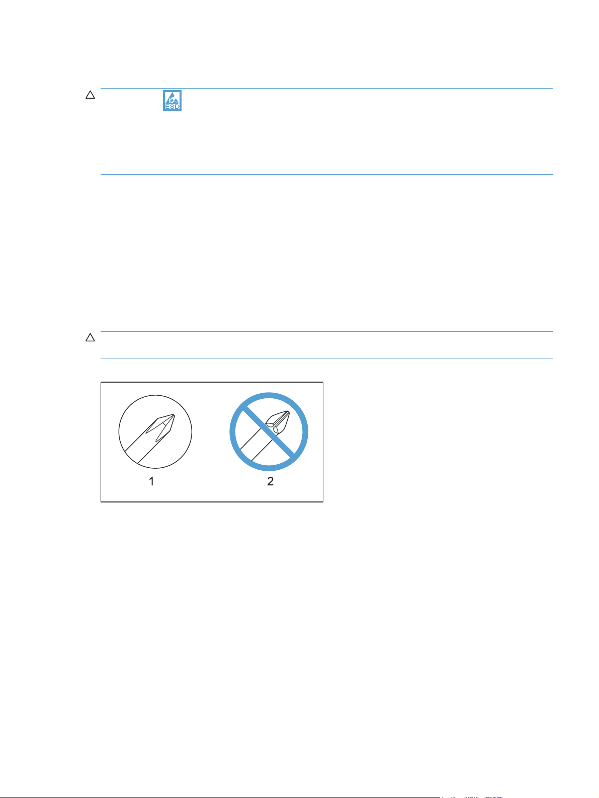
CAUTION: Always use a Phillips screwdriver (callout 1). Do not use a Pozidriv screwdriver
(callout 2) or any motorized screwdriver. These can damage screws or screw threads.
Figure 1-1 Phillips and Pozidriv screwdriver comparison
ENWW
Electrostatic discharge
3
Page 15

Service approach
Before performing service
Remove all paper from the product.
●
Turn off the power using the power button.
●
WARNING! The power button must be turned off before performing service. Failure to turn off
the power leaves the fuser engaged and prevents it removal.
Unplug the power cable and interface cable or cables.
●
Place the product on an ESD workstation or mat, or use an ESD strap (if one is available). If an
●
ESD workstation, mat, or strap is not available, ground yourself by touching the sheet-metal
chassis before touching an ESD-sensitive part.
Remove the print cartridges and imaging drum.
●
After performing service
Plug in the power cable.
●
Reinstall the print cartridge.
●
Load paper in the product.
●
Post-service test
Perform the following test to verify that the repair or replacement was successful.
Print-quality test
1. Verify that you have completed the necessary reassembly steps.
2. Make sure that the tray contains clean, unmarked paper.
3. Attach the power cord and interface cable or interface cables, and then turn on the product.
4. Verify that the expected startup sounds occur.
5. Print a configuration page, and then verify that the expected printing sounds occur.
6. Send a print job from the host computer, and then verify that the output meets expectations.
7. Clean the outside of the product with a damp cloth.
4 Chapter 1 Removal and replacement ENWW
Page 16

Parts removal order
Figure 1-2 Parts removal order
Print cartridges
Imaging drum
Input tray
Separation pad
Pickup roller
Right cover assembly
Left cover assembly
Top door assembly
Rear top cover assembly
Rear door assembly
Rear lower cover assembly
Control Panel
Front door
ITB
Fuser delivery assembly
Formatter PCA (base model)
Formatter and wireless PCA (plus model)
Engine controller assembly
Low-voltage power supply assembly
Separation pad
Right cover Left cover
Right cover Left cover
Right cover
Right cover Left cover
Right cover
Left cover
Imaging drum
Right cover
Left cover
Right cover Left cover
Left cover
Input tray Right cover Left cover
Control Panel
Rear top cover
Left cover
Rear door
Rear lower cover
Rear top cover
Top door
Rear lower cover
ENWW
Service approach
5
Page 17
Removal and replacement procedures
Replace the print cartridges
When a print cartridge approaches the end of its useful life, you can continue printing with the current
print cartridge until it no longer yields acceptable print quality.
Once an HP print cartridge has reached “very low’, HP’s Premium Protection Warranty on that supply
has ended. All print defects or print cartridge failures incurred when an HP supply is used in continue at
very low mode will not be considered to be defects in materials or workmanship in the supply under the
HP Print Cartridge Warranty Statement.
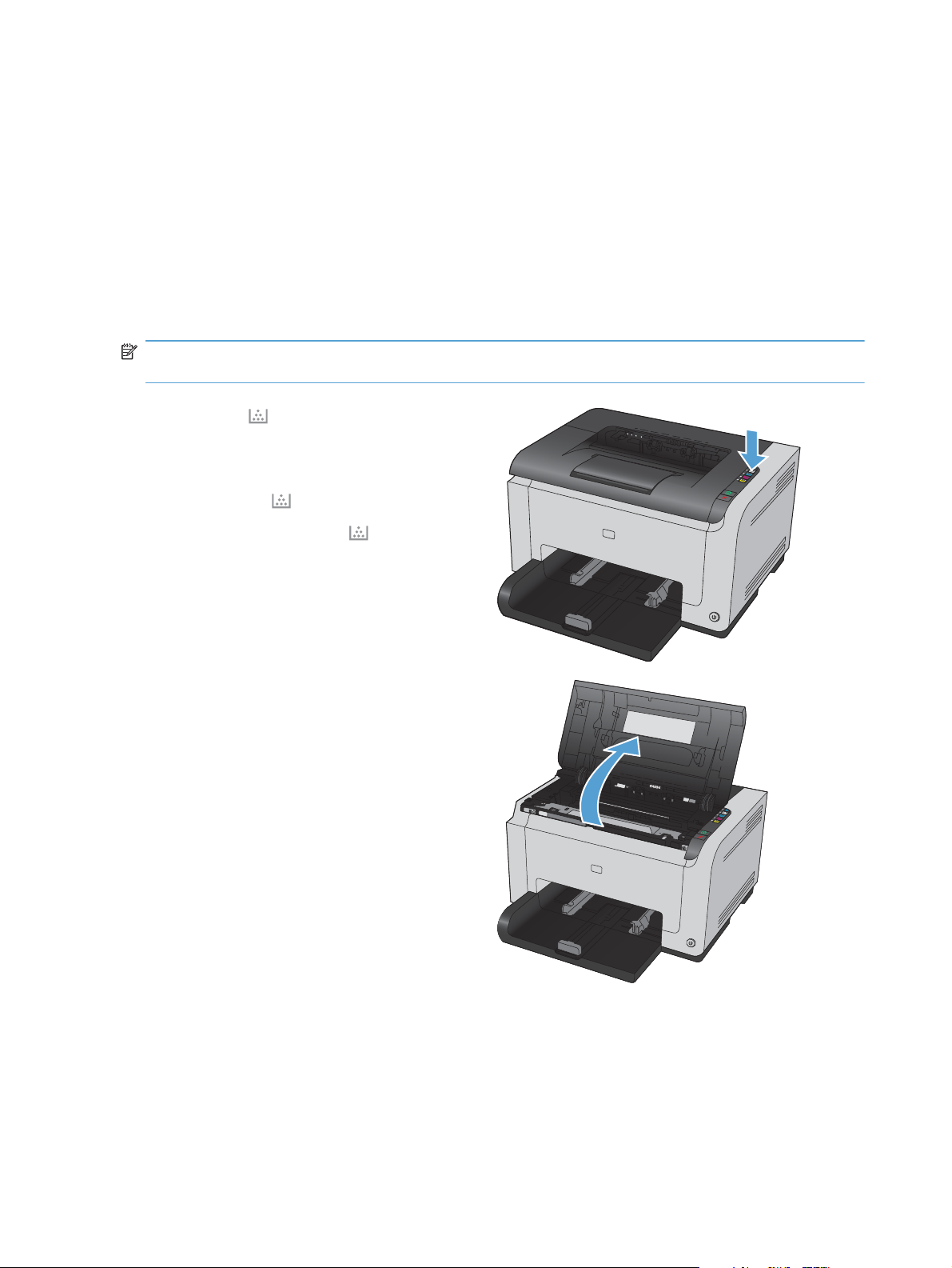
NOTE: Once an HP print cartridge has reached “very low’, the corresponding cartridge light on the
control panel turns on.
1. Press the Cartridge button of the print
cartridge that requires replacement to rotate
the print cartridge carousel for removal.
NOTE: All doors must be closed when
pressing the Cartridge
NOTE: Wait until the Cartridge
not flashing and the rotation sounds stops
before opening the print cartridge door.
2. Open the print cartridge door.
button.
light is
6 Chapter 1 Removal and replacement ENWW
Page 18
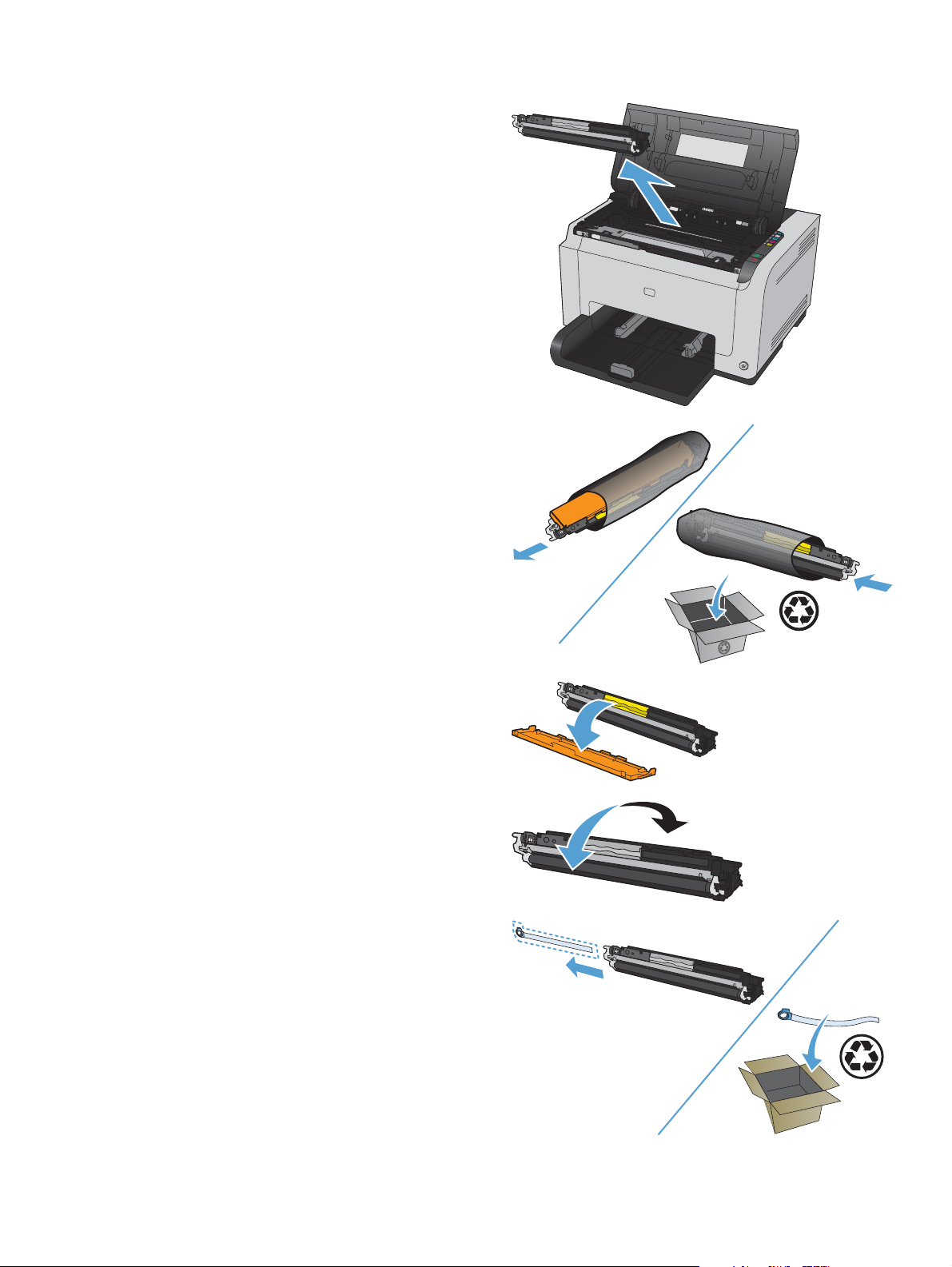
3. Grasp the old print cartridge by the center
handle and remove.
4. Remove the new print cartridge from the
packaging. Place the used print cartridge in
the bag and box for recycling.
CAUTION: To prevent damage to the print
cartridge, hold the print cartridge at each end.
Do not touch the roller on the print cartridge.
5. Remove the protective shielding from the new
print cartridge.
6. Grasp both sides of the print cartridge and
gently rock the print cartridge to distribute the
toner evenly inside the print cartridge.
7. Remove the tape from the print cartridge. Place
the tape in the print-cartridge box to return for
recycling.
ENWW
Removal and replacement procedures
7
Page 19
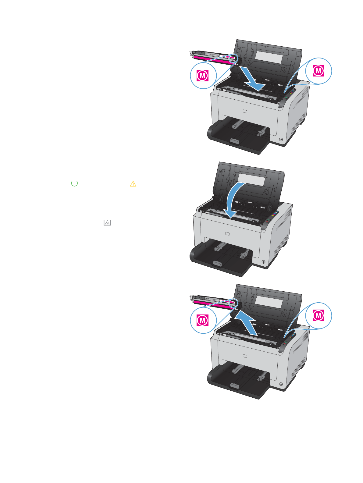
8. Grasp the print cartridge by the center handle
and insert into the product.
NOTE: Compare the color label on the print
cartridge to the color label in the carousel slot
to make sure the print cartridge color matches
the carousel position.
CAUTION: If toner gets on your clothing,
wipe it off with a dry cloth and wash the
clothing in cold water. Hot water sets toner
into the fabric.
9. Close the print cartridge door.
NOTE: After closing the print cartridge door,
the Ready
light and Attention light will
flash. Allow up to three minutes for the product
to calibrate.
NOTE: If replacing another print cartridge,
you must close the print cartridge door before
pressing the Cartridge
button of the next
print cartridge.
10. When printing, if you receive the status alert
message Wrong Cartridge in <Color>
Slot, remove the print cartridge from the
specified slot and compare the color label on
the print cartridge to the color label in the slot
to determine the correct print cartridge for the
slot.
8 Chapter 1 Removal and replacement ENWW
Page 20
Replace the imaging drum
NOTE: The imaging drum installed in this product is covered by the product warranty. Replacement
imaging drums have a one-year limited warranty from the date of installation. The imaging drum
installation date displays on both the configuration page and on the supplies status page when the
imaging drum reaches approximately 30% of its estimated remaining life. HP's Premium Protection
Warranty applies only to the print cartridges for the product.
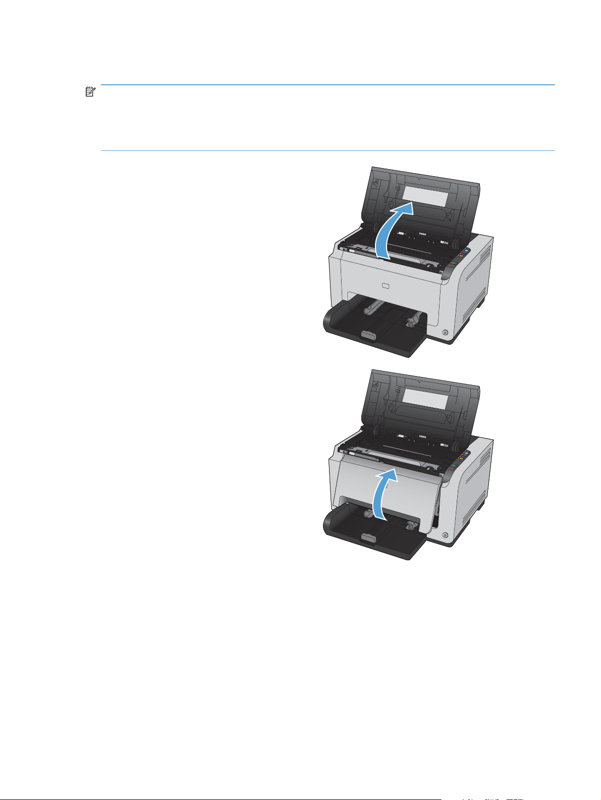
1. Open the print cartridge door.
2. Open the front cover.
ENWW
Removal and replacement procedures
9
Page 21
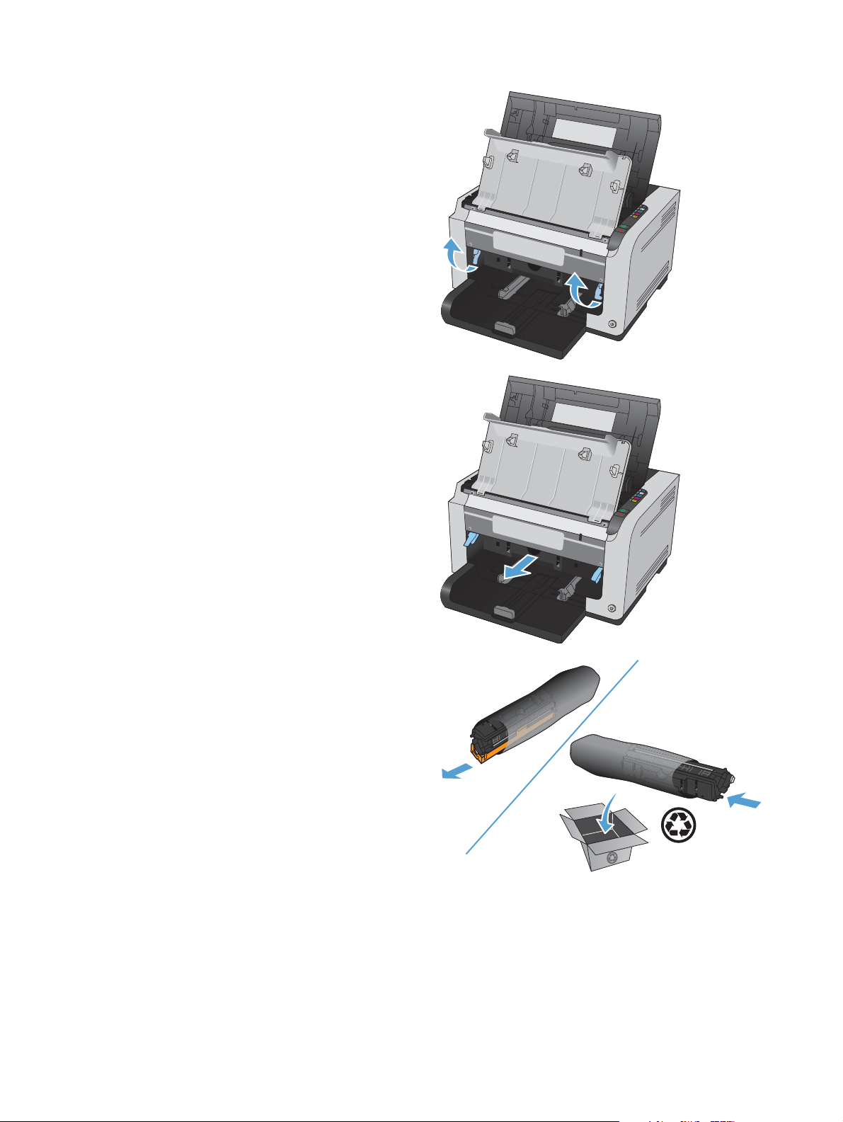
3. Lift the two levers that hold the imaging drum.
4. Remove the old imaging drum.
5. Remove the new imaging drum from the
packaging. Place the used imaging drum in
the bag and box for recycling.
10 Chapter 1 Removal and replacement ENWW
Page 22
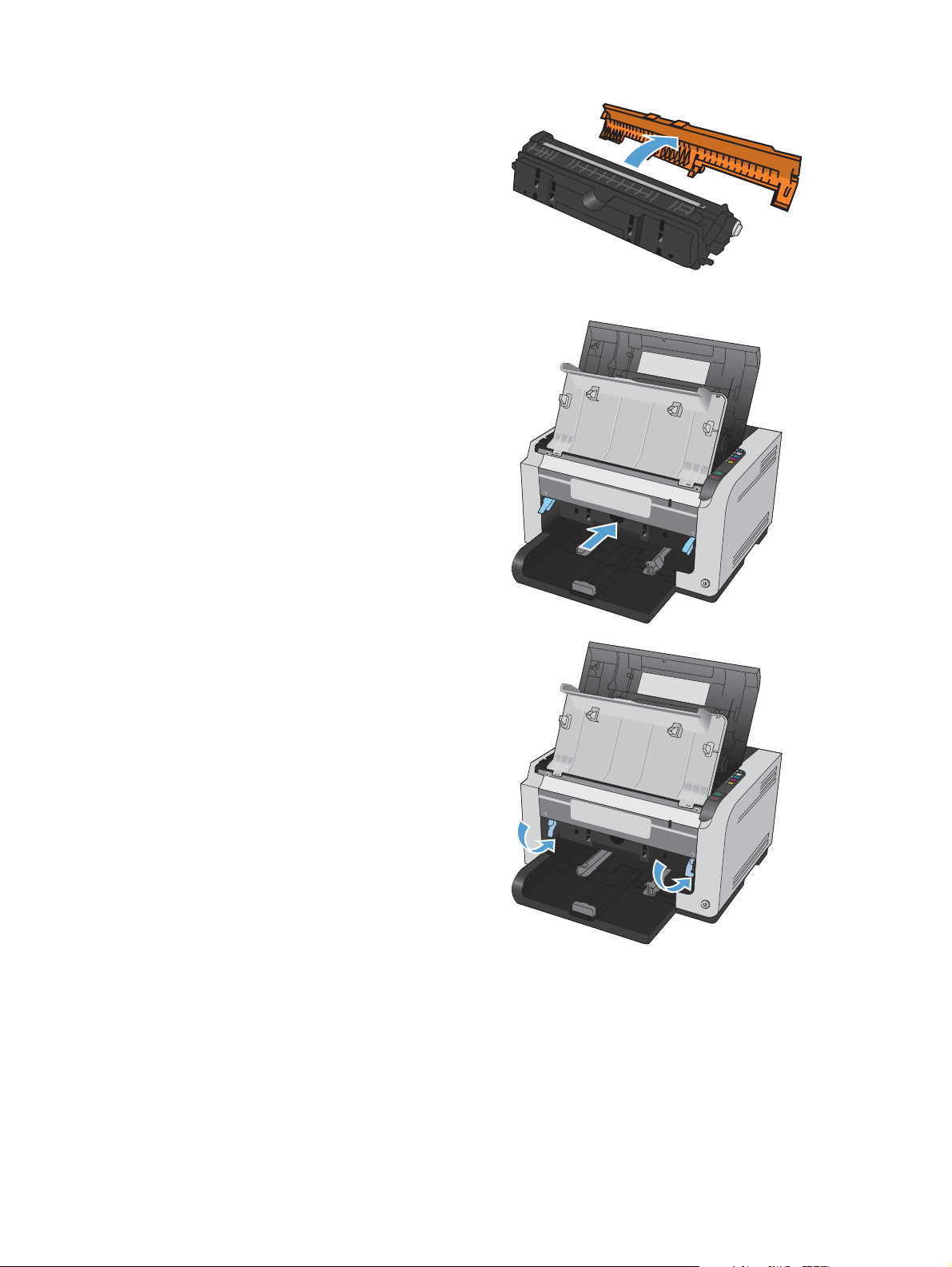
6. Remove the protective shielding from the new
imaging drum.
CAUTION: To prevent damage, do not
expose the imaging drum to light for an
extended period of time. Cover the imaging
drum with a piece of paper if it can not be
installed immediately.
CAUTION: Do not touch the green drum.
Fingerprints on the imaging drum can cause
print-quality problems.
7. Insert the new imaging drum in the product.
8. Lower the two levers that hold the imaging
drum.
ENWW
Removal and replacement procedures
11
Page 23
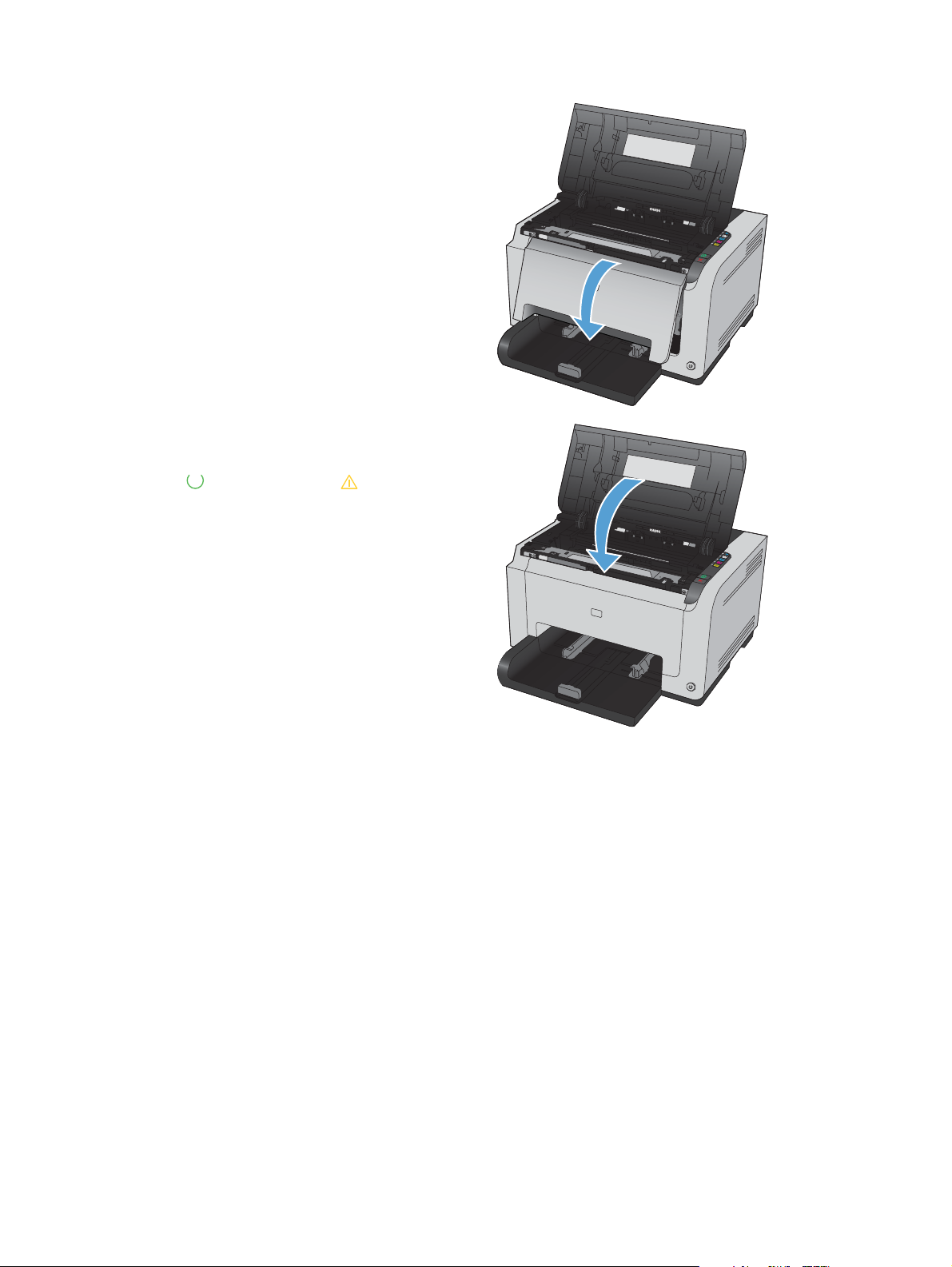
9. Close the front cover.
10. Close the print cartridge door.
NOTE: After closing the print cartridge door,
the Ready
flash. Allow up to a minute for the product to
calibrate.
light and Attention light will
12 Chapter 1 Removal and replacement ENWW
Page 24
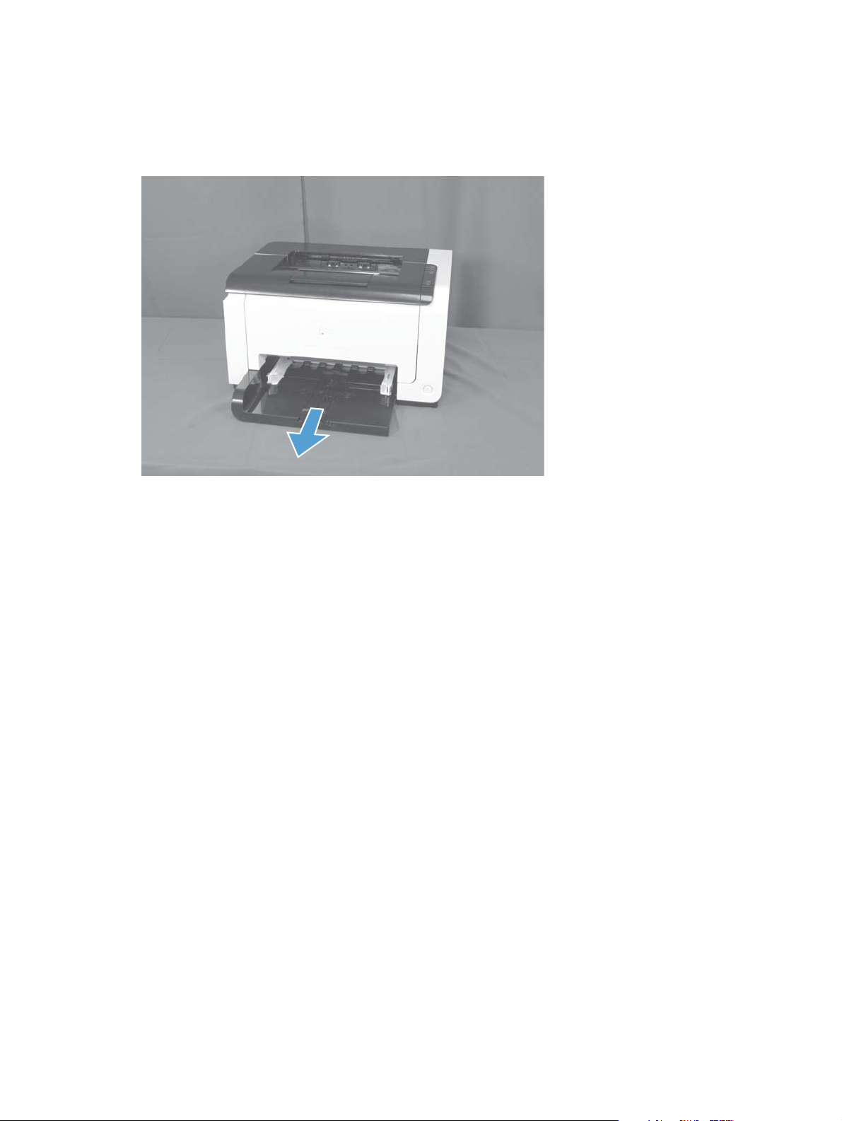
Input tray
Pull the tray away from the printer to remove.
Figure 1-3 Remove the tray
ENWW
Removal and replacement procedures
13
Page 25
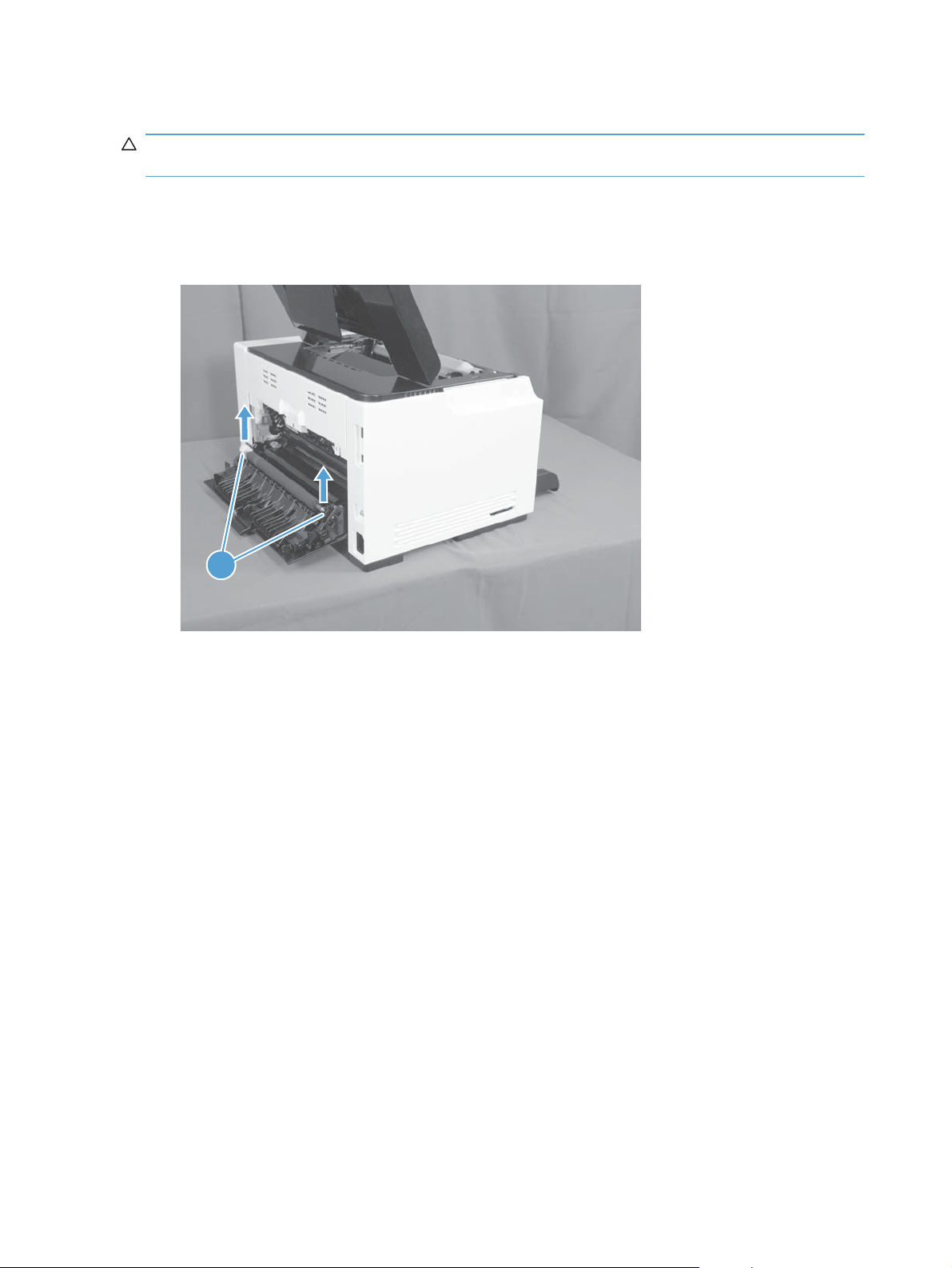
Secondary transfer roller
CAUTION: Do not touch the black spongy part of the roller. Skin oils might cause print-quality
problems.
1. Open the rear door.
2. Release two clips (callout 1), and then remove the roller form the product.
Figure 1-4 Remove the secondary transfer roller
1
14 Chapter 1 Removal and replacement ENWW
Page 26
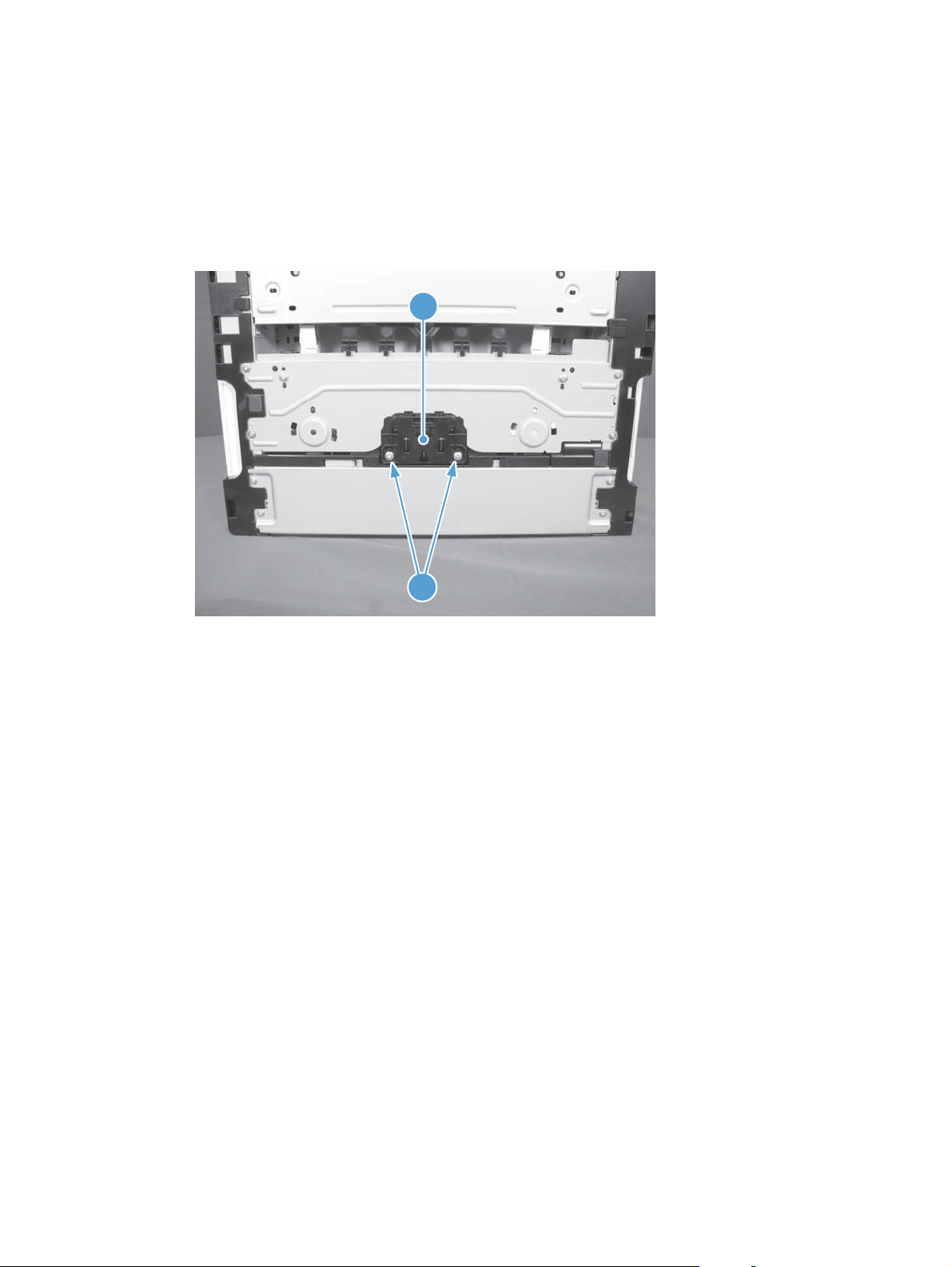
Separation pad assembly
Remove the separation pad assembly
1. Turn the product front side up.
2. Remove two screws (callout 1) and the separation pad assembly (callout 2).
Figure 1-5 Remove the separation pad assembly (1 of 1)
2
1
ENWW
Removal and replacement procedures
15
Page 27

Pickup roller
Rotate the pickup roller to the service position
To gain access to the roller locking tabs you must rotate the roller to the correct position for removal.
1. When the product is in the Ready state, press and hold the Auto-On/Auto-Off (power) button for
about seven seconds or until the Ready
TIP: Optionally, unplug the power cord, and then plug the cord back in.
2. Make sure that one sheet of paper is loaded in the input tray.
NOTE: If more than one sheet of paper is loaded in the tray, this procedure will not be
successful.
3. Press and release the Auto-On/Auto-Off (power) button and within two seconds press and hold
down the cyan cartridge button. Hold the cyan button down for about five seconds, or until the
initialization process begins.
NOTE: Immediately after the Auto-On/Auto-Off (power) button is pressed, all of the control
panel lights illuminate briefly (for about two seconds). You must press the cyan cartridge button
while the lights are illuminated.
4. When the product finishes initializing, the roller rotates into the removal position. Turn the product
off. Unplug the product before removing any components.
light turns off.
NOTE: When the roller is in the removal position, the sheet of paper will have been pulled into
the paper path by about 12 mm (.5 in). This is visual confirmation that the roller has rotated to the
removal position.
Before proceeding, remove the following components:
Right cover assembly. See
●
Left cover assembly. See
●
Separation pad assembly. See
●
Right cover assembly on page 18.
Left cover assembly on page 19.
Separation pad assembly on page 15.
16 Chapter 1 Removal and replacement ENWW
Page 28
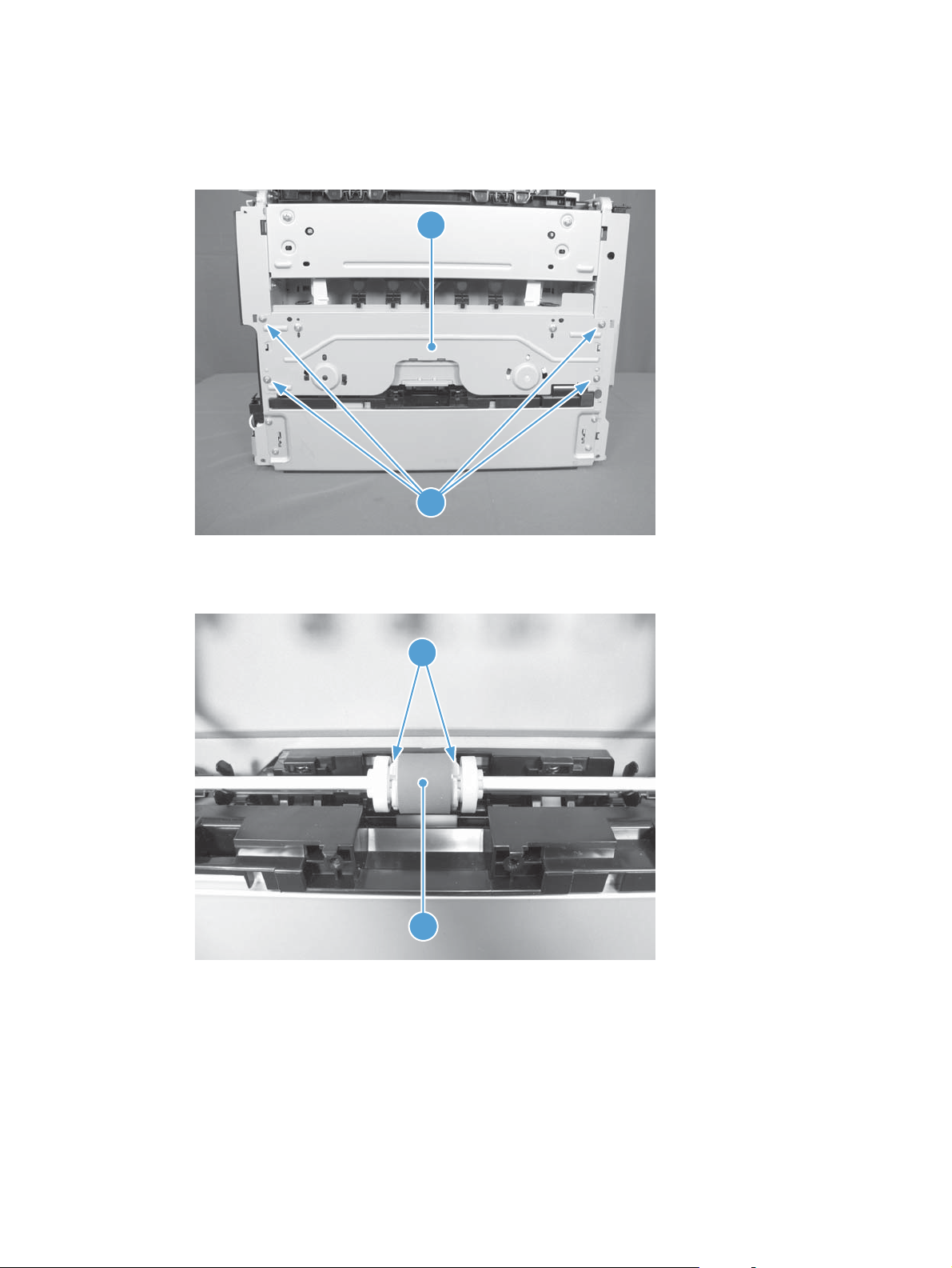
Remove the pickup roller assembly
1. Remove four screws (callout 1) and the lower stay part (callout 2).
Figure 1-6 Remove the pickup roller assembly (1 of 2)
2
1
2. Release two tabs (callout 1) and remove the pickup roller (callout 2).
Figure 1-7 Remove the pickup roller assembly (2 of 2)
1
2
ENWW
Removal and replacement procedures
17
Page 29
Covers
Right cover assembly
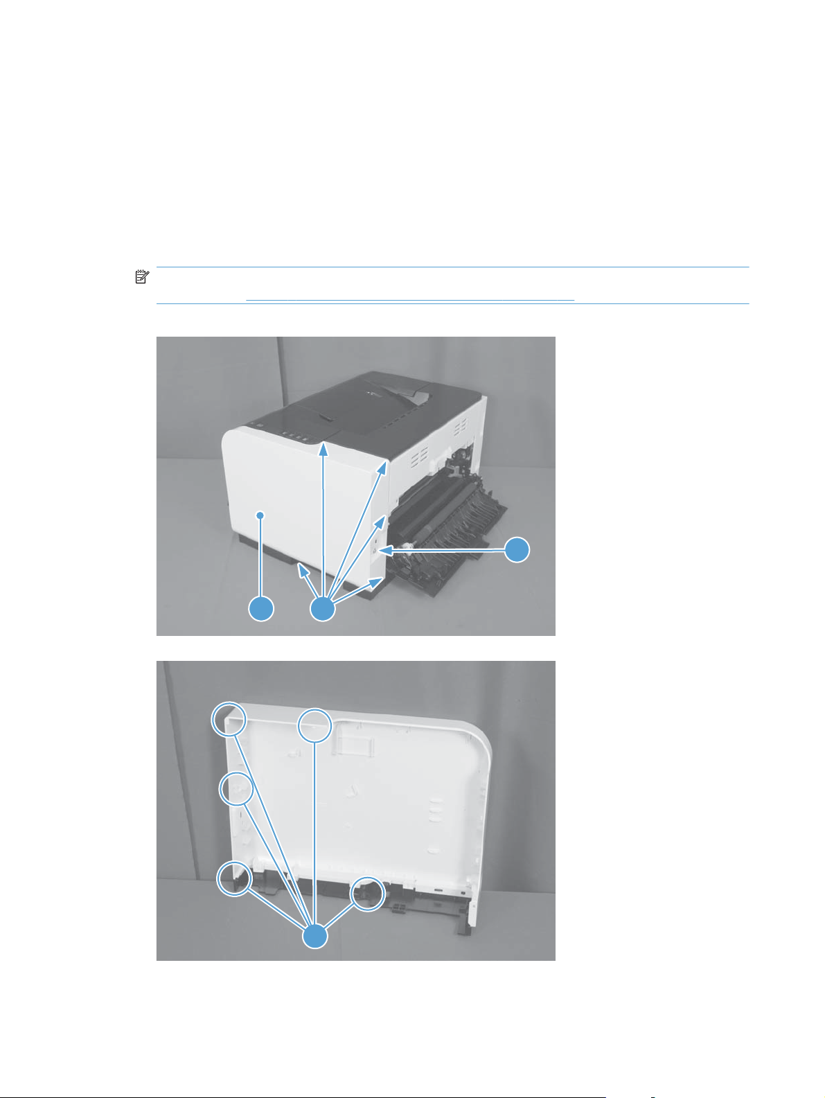
Remove the right cover assembly
1. Open the top and rear door assemblies.
2. Remove one screw (callout 1), and then starting at the rear vertical edge, release five tabs (callout
2) and remove the right cover assembly (callout 3).
NOTE: Before proceeding, take note of the locations of the tabs (callout 1) on the back side of
the cover. See
Figure 1-8 Remove the right cover (1 of 2)
Figure 1-9 Remove the right cover (2 of 2) on page 18.
3
Figure 1-9 Remove the right cover (2 of 2)
2
2
1
18 Chapter 1 Removal and replacement ENWW
Page 30
Left cover assembly
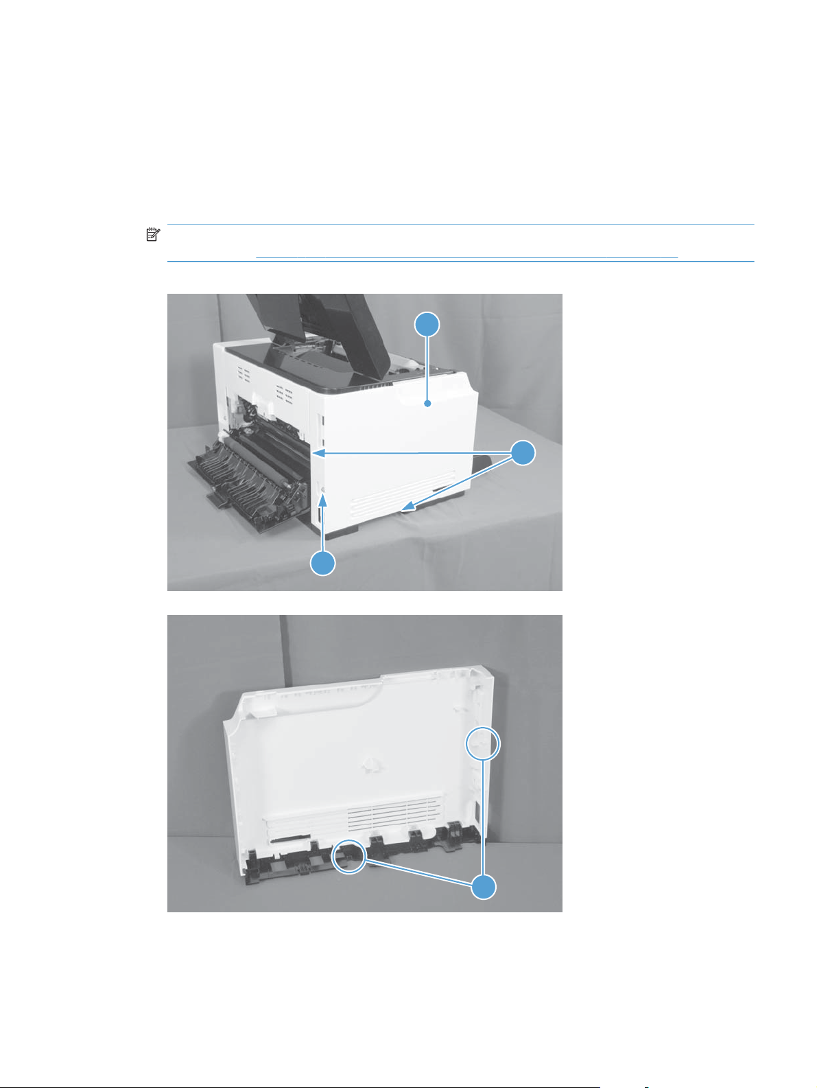
Remove the left cover assembly
1. Open the top door.
2. Remove one screw (callout 1), and then starting at the rear vertical edge, release two tabs (callout
2) and remove the left cover assembly (callout 3).
NOTE: Before proceeding, take note of the locations of the tabs (callout 2) on the back side of
the cover. See
Figure 1-10 Remove the left cover (1 of 2)
Figure 1-11 Remove the left cover, duplex product (2 of 2) on page 19.
3
2
1
Figure 1-11 Remove the left cover, duplex product (2 of 2)
2
ENWW
Removal and replacement procedures
19
Page 31

Top door assembly
Before proceeding, remove the following components:
Right cover assembly. See
●
Left cover assembly. See
●
Remove the top door assembly
1. Remove one screw (callout 1).
Figure 1-12 Remove the top door assembly (1 of 3)
Right cover assembly on page 18.
Left cover assembly on page 19.
1
2. Use a small, flat blade screwdriver to release the five tabs between the top door assembly and the
rear top cover.
Figure 1-13 Remove the top door assembly (2 of 3)
20 Chapter 1 Removal and replacement ENWW
Page 32

3. Lift the top door and rear edge, then slide the top door assembly forward to release the two tabs
from the drive shaft at the top of the product.
Figure 1-14 Remove the top door assembly (3 of 3)
ENWW
Removal and replacement procedures
21
Page 33

Rear top cover assembly
Before proceeding, remove the following components:
Right cover assembly. See
●
Left cover assembly. See
●
Top door assembly. See
●
Remove the rear top cover assembly
Release one tab (callout 1) and remove the rear top cover (callout 2).
▲
Figure 1-15 Remove the top door (1 of 2)
Left cover assembly on page 19.
Top door assembly on page 20.
Right cover assembly on page 18.
2
1
Figure 1-16 Remove the top door (2 of 2)
1
22 Chapter 1 Removal and replacement ENWW
Page 34

Rear door assembly
Before proceeding, remove the following components:
Right cover assembly. See
●
Remove the rear door assembly
1. Remove one screw (callout 1) and the bushing (callout 2).
Figure 1-17 Remove the rear door assembly (1 of 2)
Right cover assembly on page 18.
1
2
2. Pull out the shaft (callout 1) and remove the rear door assembly (callout 2).
Figure 1-18 Remove the rear door assembly (2 of 2)
1
2
ENWW
Removal and replacement procedures
23
Page 35

Rear lower cover assembly
Before proceeding, remove the following components:
Right cover assembly. See
●
Left cover assembly. See
●
Rear door assembly. See
●
Remove the rear lower cover assembly
Remove two screws (callout 1) and the rear lower cover assembly (callout 2).
Figure 1-19 Remove the lower cover assembly
Right cover assembly on page 18.
Left cover assembly on page 19.
Rear door assembly on page 23.
1
2
24 Chapter 1 Removal and replacement ENWW
Page 36

Control panel
CAUTION: ESD sensitive.
Before proceeding, remove the following components:
Right cover assembly. See
●
Remove the control panel
1. Open the top door assembly.
2. Remove two screws (callout 1) and disconnect one connector (callout 2).
Figure 1-20 Remove the control panel (1 of 2)
Right cover assembly on page 18.
1
4
2
ENWW
Removal and replacement procedures
25
Page 37

3. Release one tab (callout 3) and remove the control panel (callout 4).
Figure 1-21 Remove the control panel (2 of 2)
3
26 Chapter 1 Removal and replacement ENWW
Page 38

Front door
Before proceeding, remove the following components:
Right cover assembly. See
●
Left cover assembly. See
●
Control panel. See
●
Remove the front door
1. Open the front door.
2. Remove four screws (callout 1) and the scanner cover (callout 2).
Figure 1-22 Remove the front door (1 of 2)
Right cover assembly on page 18.
Left cover assembly on page 19.
Control panel on page 25.
1
2
ENWW
Removal and replacement procedures
27
Page 39

3. Release one tab (callout 1) and slide the front door (callout 2) in the direction that the arrow
indicates to remove it.
Figure 1-23 Remove the front door (2 of 3)
2
1
28 Chapter 1 Removal and replacement ENWW
Page 40

Main assemblies
ITB assembly
CAUTION: ESD sensitive.
Before proceeding, remove the following components:
Imaging drum. See
●
Rear top cover assembly. See
●
Rear lower cover assembly. See
●
Remove the ITB assembly
1. For wireless products, follow these steps to remove the wireless PCA.
a. Release one tab (callout 1) and disconnect one connector (callout 2) on the back of the
wireless PCA.
Figure 1-24 Remove the ITB assembly (1 of 16)
Replace the imaging drum on page 9.
Rear top cover assembly on page 22.
Rear lower cover assembly on page 24.
1
2
ENWW
b. Remove three screws (callout 1).
NOTE: Base products have only two screws and the appearance of the formatter may be
slightly different from what appears in
on page 29.
Figure 1-24 Remove the ITB assembly (1 of 16)
Removal and replacement procedures
29
Page 41

2. Disconnect three connectors (callout 2) and remove the formatter (callout 3).
Figure 1-25 Remove the ITB assembly (2 of 16)
3
2
1
3. Release one tab (callout 1) and remove the cable cover (callout 2).
Figure 1-26 Remove the ITB assembly (3 of 16)
2
1
4. Disconnect one connector (callout 1).
30 Chapter 1 Removal and replacement ENWW
Page 42

5. Release cables (callout 4) from the cable clips (callout 2) and the cable guide (callout 3).
Figure 1-27 Remove the ITB assembly (4 of 16)
4
1
3
2
6. Release one tab (callout 1) and remove the left side arm (callout 2) of the rear door.
Figure 1-28 Remove the ITB assembly (5 of 16)
ENWW
2
1
Removal and replacement procedures
31
Page 43

7. Release the hook (callout 1) of the ITB fuser spring and turn the spring (callout 2) frontward.
Figure 1-29 Remove the ITB assembly (6 of 16)
3
2
Figure 1-30 Remove the ITB assembly (7 of 16)
2
32 Chapter 1 Removal and replacement ENWW
Page 44

8. Turn the ITB fuser part (callout 1) frontward (callout 2).
Figure 1-31 Remove the ITB assembly (8 of 16)
1
Figure 1-32 Remove the ITB assembly (9 of 16)
2
ENWW
Removal and replacement procedures
33
Page 45

9. Release two tabs (callout 1) and remove the spring cover (callout 2).
Figure 1-33 Remove the ITB assembly (10 of 16)
1
2
10. Release one tab (callout 1) and remove the right side arm (callout 2) of the rear door.
Figure 1-34 Remove the ITB assembly (11 of 16)
1
2
34 Chapter 1 Removal and replacement ENWW
Page 46

11. Pull out the cables (callout 1), release the hook (callout 2) of the ITB fuser spring, and then turn the
spring (callout 3) frontward.
Figure 1-35 Remove the ITB assembly (12 of 16)
1
2
3
Figure 1-36 Remove the ITB assembly (13 of 16)
ENWW
2
Removal and replacement procedures
35
Page 47

12. Turn the ITB fuser part (callout 1) frontward.
Figure 1-37 Remove the ITB assembly (14 of 16)
Figure 1-38 Remove the ITB assembly (15 of 16)
1
1
36 Chapter 1 Removal and replacement ENWW
Page 48

13. Pull out the ITB assembly (callout 1).
CAUTION: Avoid touching the black plastic transfer belt. Skin oils on the belt might cause print-
quality problems.
Figure 1-39 Remove the ITB assembly (16 of 16)
1
ENWW
Removal and replacement procedures
37
Page 49

Fuser delivery assembly
NOTE: For this product, the fuser and the paper delivery components are one assembly.
Position the fuser pressure roller for removal
You must rotate the pressure roller to the correct position before removing the fuser delivery assembly.
1. When the product is in the Ready state, press and hold the Auto-On/Auto-Off (power) button for
about seven seconds or until you hear subtle movement within the product and the Ready
turns off.
2. Release the Auto-On/Auto-Off (power) button. The product power will be off and the fuser
pressure roller is in the removal position. Unplug the product before removing any components.
Before proceeding, remove the following components:
light
●
Left cover assembly. See
●
Top door assembly. See
●
Rear top cover assembly. See
●
Formatter (base model) or formatter and wireless PCA (plus model). See
●
model) on page 43 or Formatter and wireless PCA (plus model) on page 44.
Left cover assembly on page 19.
Top door assembly on page 20.
Rear top cover assembly on page 22.
Right cover assembly. See
Right cover assembly on page 18 .
Formatter PCA (base
38 Chapter 1 Removal and replacement ENWW
Page 50

Remove the fuser delivery assembly
CAUTION: ESD sensitive.
1. Release one tab (callout 1) and disconnect one connector (callout 2) on the back of the wireless
PCA.
Figure 1-40 Remove the fuser delivery assembly (1 of 6)
2
1
2. Remove three screws (callout 1).
3. Disconnect three connectors (callout 2) and the formatter (callout 3).
Figure 1-41 Remove the fuser delivery assembly (2 of 6)
3
2
1
ENWW
Removal and replacement procedures
39
Page 51

4. Release one tab (callout 1) and remove the cable cover (callout 2).
Figure 1-42 Remove the fuser delivery assembly (3 of 6)
2
1
5. Disconnect four connectors (callout 1).
6. Release cables (callout 4) from the cable clips (callout 2) and the cable guide (callout 3).
Figure 1-43 Remove the fuser delivery assembly (4 of 6)
2
3
4
1
40 Chapter 1 Removal and replacement ENWW
Page 52

7. Remove two screws (callout 1) and the carousel cover (callout 2).
Figure 1-44 Remove the fuser delivery assembly (5 of 6)
2
1
8. Remove six screws (callout 1) and the fuser delivery assembly (callout 2).
Figure 1-45 Remove the fuser delivery assembly (6 of 6)
1
2
ENWW
Removal and replacement procedures
41
Page 53

Reassemble the fuser delivery assembly
When reassembling the fuser delivery assembly, be sure the drive cam (callout 1) for fuser
▲
pressure release is positioned as shown in the figures below.
Figure 1-46 Reassemble the fuser delivery assembly (1 of 2)
1
Figure 1-47 Reassemble the fuser delivery assembly (2 of 2)
1
42 Chapter 1 Removal and replacement ENWW
Page 54

Formatter PCA (base model)
CAUTION: ESD sensitive.
Before proceeding, remove the following components:
Left cover assembly. See
●
Remove the formatter PCA (base model)
1. Disconnect three connectors (callout 1).
Figure 1-48 Remove the formatter PCA (base model; 1 of 2)
Left cover assembly on page 19.
1
ENWW
2. Remove three screws (callout 1), and then remove the formatter PCA.
Figure 1-49 Remove the formatter PCA (base model; 2 of 2)
1
Removal and replacement procedures
43
Page 55

Formatter and wireless PCA (plus model)
CAUTION: ESD sensitive.
Before proceeding, remove the following components:
Right cover assembly. See
●
Left cover assembly. See
●
Top door assembly. See
●
Remove the formatter and wireless PCA (plus model)
1. Release two tabs (callout 1), and then remove the wireless PCA (callout 2).
Figure 1-50 Remove the formatter and wireless PCA (plus model; 1 of 2)
Right cover assembly on page 18.
Left cover assembly on page 19.
Top door assembly on page 20.
2
1
44 Chapter 1 Removal and replacement ENWW
Page 56

2. Disconnect three connectors (callout 1), remove three screws (callout 2), and then remove the
formatter PCA.
Figure 1-51 Remove the formatter and wireless PCA (plus mode; 2 of 2)
2
1
ENWW
Removal and replacement procedures
45
Page 57

Engine controller assembly
CAUTION: ESD sensitive.
Before proceeding, remove the following components:
Left cover assembly. See
●
Remove the engine controller assembly
1. Release one tab (callout 1) and disconnect one connector (callout 2) on the back of the wireless
PCA.
Figure 1-52 Remove the engine controller assembly (1 of 5)
Left cover assembly on page 19.
1
2
2. Remove three screws (callout 1).
46 Chapter 1 Removal and replacement ENWW
Page 58

3. Disconnect three connectors (callout 2) and the formatter (callout 3).
Figure 1-53 Remove the engine controller assembly (2 of 5)
3
2
1
4. Release one tab (callout 1) and remove the cable cover (callout 2).
Figure 1-54 Remove the engine controller assembly (3 of 5)
ENWW
2
1
Removal and replacement procedures
47
Page 59

5. Disconnect all of eleven connectors (callout 1) on the engine controller assembly.
Figure 1-55 Remove the engine controller assembly (4 of 5)
1
6. Remove six screws (callout 1).
7. Release two tabs (callout 2) and the engine controller assembly (callout 3).
Figure 1-56 Remove the engine controller assembly (5 of 5)
1
2
3
48 Chapter 1 Removal and replacement ENWW
Page 60

Low-voltage power supply assembly
CAUTION: ESD sensitive.
Before proceeding, remove the following components:
Input tray. See
●
Right cover assembly. See
●
Left cover assembly. See
●
Rear lower cover assembly. See
●
Remove the low-voltage power supply assembly
1. Remove two screws (callout 1) and disconnect one connector (callout 2).
Figure 1-57 Remove the low-voltage power supply assembly (1 of 6)
Input tray on page 13.
Right cover assembly on page 18.
Left cover assembly on page 19.
Rear lower cover assembly on page 24.
1
ENWW
2
2. Release the cables (callout 1).
Removal and replacement procedures
49
Page 61

3. Release two tabs (callout inlet part (callout 3).
Figure 1-58 Remove the low-voltage power supply assembly (2 of 6)
2
3
4. Disconnect one connector (callout 1).
5. Release the cables (callout 3) from the cable guide (callout 2).
Figure 1-59 Remove the low-voltage power supply assembly (3 of 6)
1
1
3
2
6. Turn the product rear side up.
50 Chapter 1 Removal and replacement ENWW
Page 62

7. Remove four screws (callout 1).
Figure 1-60 Remove the low-voltage power supply assembly (4 of 6)
1
8. Remove three screws (callout 1).
9. Disconnect one connector (callout 2) and pull out the low-voltage power supply assembly
(callout 3).
Figure 1-61 Remove the low voltage power supply assembly (5 of 6)
2 3
1
ENWW
Removal and replacement procedures
51
Page 63

10. Disconnect three connectors (callout 1) and remove the low-voltage power supply assembly
(callout 2).
Figure 1-62 Remove the low-voltage power supply assembly (6 of 6)
1
2
52 Chapter 1 Removal and replacement ENWW
Page 64

2 Solve problems
Solve problems checklist
●
Troubleshooting process
●
Tools for troubleshooting
●
Clear jams
●
The product does not feed automatically
●
The product feeds multiple sheets
●
Solve image-quality problems
●
Clean the product
●
Solve performance problems
●
Solve connectivity problems
●
Service mode functions
●
Product updates
●
ENWW 53
Page 65

Solve problems checklist
Follow these steps when trying to solve a problem with the product.
Step 1: Make sure that the product is set up correctly
●
Step 2: Check the cabling or wireless connection (network models only)
●
Step 3: Check to see if any control-panel lights are lit
●
Step 4: Check the paper
●
Step 5: Check the software
●
Step 6: Test print functionality
●
Step 7: Check the supplies
●
Step 8: Try sending a print job from a computer
●
Step 1: Make sure that the product is set up correctly
Make sure that the product is set up correctly.
1. Press the power button to turn on the product or to deactivate the Auto-On\Auto-Off mode.
2. Check the power-cable connections.
3. Make sure that the line voltage is correct for the product power configuration. (See the label that is
on the back of the product for voltage requirements.) If you are using a power strip and its voltage
is not within specifications, plug the product directly into the wall. If it is already plugged into the
wall, try a different outlet.
4. Make sure that the imaging-drum-cartridges are installed correctly.
5. Print an engine test page to verify the engine is functioning.
Step 2: Check the cabling or wireless connection (network models
only)
1. Check the cable connection between the product and the computer. Make sure that the connection
is secure.
2. Make sure that the cable itself is not faulty by using a different cable, if possible.
Step 3: Check to see if any control-panel lights are lit
The control panel should indicate ready status. If an error message appears, resolve the error.
Step 4: Check the paper
1. Make sure that the paper that you are using meets specifications.
2. Make sure that the paper is loaded correctly in the input tray.
54 Chapter 2 Solve problems ENWW
Page 66

Step 5: Check the software
1. Make sure that the product software is installed correctly.
2. Verify that you have installed the printer driver for this product. Check the program to make sure
that you are using the printer driver for this product.
Step 6: Test print functionality
1. Print a configuration page. Select Print configuration page on the Services tab in the Printer
Preferences.
2. If the page does not print, verify that the input tray contains paper.
3. If the page jams in the product, clear the jam.
Step 7: Check the supplies
Print a supplies status page and check remaining life of the print cartridges and imaging drum.
Step 8: Try sending a print job from a computer
1. Try printing the job from another computer that has the product software installed.
2. Check the USB cable connection. Direct the product to the correct port, or reinstall the software,
selecting the connection type that you are using.
3. If the print quality is unacceptable, complete the following steps:
Verify that the print settings are correct for the media that you are using.
●
ENWW
Solve problems checklist
55
Page 67

Troubleshooting process
Determine the problem source
The following table includes basic questions to ask the customer to quickly help define the problem or
problems.
General topic Questions
Environment
Paper
Input tray
Is the product installed on a solid, level surface (± 1°)?
●
Is the power-supply voltage within ± 10 volts of the specified power source?
●
Is the power-supply plug inserted in the product and the outlet?
●
Is the operating environment within the specified parameters?
●
Is the product exposed to ammonia gas, such as that produced by diazo
●
copiers or office cleaning materials?
NOTE: Diazo copiers produce ammonia gas as part of the coping
processes. Ammonia gas (from cleaning supplies or a diazo copier) can have
an adverse affect on some product components (for example, the imaging
drum).
Is the product exposed to direct sunlight?
●
Does the customer use only supported paper?
●
Is the paper in good condition (no curls, folds, or distortion)?
●
Is the paper stored correctly and within environmental limits?
●
Is the amount of paper in the tray within specifications?
●
Is the paper correctly placed in the tray?
●
Are the paper guides aligned with the stack?
●
Cartridge
Transfer roller and fuser
Covers
Condensation
Miscellaneous
Are the developing cartridges and the imaging-drum installed correctly and
●
firmly seated?
Are the transfer roller and fuser installed correctly?
●
Are the top, front and rear doors firmly closed?
●
Does condensation occur following a temperature change (particularly in
●
winter following cold storage)? If so, wipe affected parts dry or leave the
product on for 90 to 120 minutes.
Was a cartridge opened soon after being moved from a cold to a warm
●
room? If so, allow the cartridge to sit at room temperature for 1 to 2 hours.
Check for and remove any non-HP components (for example, a print cartridge)
●
from the product.
Remove the product from the network and make sure that the failure is with the
●
product before beginning troubleshooting.
56 Chapter 2 Solve problems ENWW
Page 68

Power subsystem
Power-on checks
Turn on the power. If the control-panel LEDs do not illuminate, perform the power-on checks to find the
cause of the problem.
1. Verify that the product is plugged into an active electrical outlet that delivers the correct voltage.
2. Verify that the power button is in the on position.
3. Make sure that the product makes the expected start up sounds.
NOTE: The overcurrent/overvoltage protection circuit in the low-voltage power supply unit might
be functioning. Turn the product off, unplug the power cord, and turn the product on. If the
product does not function, the fuse melts, or the power supply is malfunctioning, replace the
engine controller unit. See
Engine controller assembly on page 46.
ENWW
Troubleshooting process
57
Page 69

Tools for troubleshooting
Component diagnostics
Engine diagnostics
Printing an engine test page helps determine if the product engine is functioning. Use the following
procedure to print a test page to make sure that the product engine is functioning
Engine test page
NOTE: The product does not have a test-print switch.
1. When the product is in the Ready state, press and hold the Auto-On/Auto-Off (power) button for
about seven seconds or until the Ready
TIP: Optionally, unplug the power cord, and then plug the cord back in.
2. Make sure that at least one sheet of paper is loaded in the input tray.
3. Open the top door (print-cartridge door).
4. Release the rear door and allow it to open to its first stop position; open about 19 mm (.75 in).
light turns off.
5. Press and hold the Auto-On/Auto-Off (power) button.
NOTE: The control-panel lights cycle on and off sequentially twice, starting with the black-
cartridge light (top) and ending with the Ready
6. When the black-cartridge light turns on for the second time—the beginning of the second cycle—
close the rear door, and then within five seconds close the top door (print-cartridge door).
7. When the product finishes initializing, an engine test page prints.
Figure 2-1 Engine test page
light.
58 Chapter 2 Solve problems ENWW
Page 70

Diagrams
Plug/jack locations
Figure 2-2 Plug/jack locations
1
1 Kensington lock
2 Rear jam-access door
2
3
4
5
3 HP internal network port (network models only)
4 USB port
5 Power receptacle
ENWW
Tools for troubleshooting
59
Page 71

Locations of connectors
Figure 2-3 Locations of connectors
J103
Item Description Item Description Item Description
J128
J130
J106
J107
J119
J102
J108
J101
J109
J152
J104
J110
J112
J140
J101 Not used J107 Media width
sensor (SR1)
Delivery sensor
(SR2)
J102 Not used J108 Low-voltage power
supply
TOP sensor (SR6)
J103 Formatter J109 Memory tag
Scanner motor
(M5)
Power switch PCA
Carousel home
sensor (SR7)
J104 Scanner assembly
(laser drive PCA)
J110 Carousel motor
(M1)
Fuser motor (M2)
J106 Loop sensor (SR3) J112 Pickup motor (M3)
T2 roller and ITB
cleaner solenoid
(SL1)
J119 Fuser pressure
release sensor
(SR4)
J128 Rear door open
detection switch
(SW1)
J130 ITB
J140 Low-voltage power
supply
J152 Not used
60 Chapter 2 Solve problems ENWW
Page 72

Locations of major components
Figure 2-4 External view
1
9
8
7
6
5
2
3
4
ENWW
Item Description Item Description
1 Top door assembly 6 Rear door assembly
2 Control panel 7 Rear top cover
3 Right cover 8 Input tray
4 Left cover 9 Front door
5 rear bottom cover
Tools for troubleshooting
61
Page 73

Figure 2-5 Cross section view
Item Description Item Description
1 Pressure roller 10 T1 pad
2 Delivery roller 11 ITB
3 Fuser film assembly 12 Pickup roller
4 Density ITB_TOP sensor 13 Separation pad
5 Developing-cartridge 14 Feed roller
6 Imaging drum 15 T2 roller
7 Imaging-drum 16 ITB drive roller
8 Laser scanner assembly 17 ITB cleaning brush
9 Input tray 18 ITB cleaning roller
62 Chapter 2 Solve problems ENWW
Page 74

General timing chart
Figure 2-6 General timing diagram
PRINTINTR LSTR
ENWW
Print command
STBY STBY
Operation
Timing chart two consecutive prints on LTR paper (Full-color 1/1 speed mode)
1 Cassette pickup solenoid
TOP sensor3
2 Pickup motor
Fuser motor
4 Delivery sensor
5
Main motor7
6 Scanner motor
8 TOP signal
9 ITB_TOP signal
12 Developing bias
11 Carousel motor
10 Primary charging bias
T1 bias
T2 roller ITB cleaner solenoid
13
14
15 T2 bias
Tools for troubleshooting
63
Page 75

General circuit diagram
Figure 2-7 Circuit diagram
D
Laser Driver PCA
/BDI
+3.3T
10
11
ITB Ass’y
J801
11
412356789
SGND
LDPWM
SGND
J104
1
DNSP
DNSGAIN1
ITBTOPPWM
98 2345617
SR3
J601
123
LOOPSNS
SGND
321
J106
LDCNT0
+3.3T
11
DNSGAIN0
LDCNT1
SGND
412356789
J130
6543289
DNSPWM
ITBTOPSNS
J611
TH801
12
21
J7L
J7D
J7DH
Scanner Ass’y
10
11
SOLD3
SOLD4
Memory TAG
12
J8L
21
J8D
SGND
VDO
/VDO
J8DH
VIN
CVSS
18 17 16 15 14 13 12 11 10 9 8 234561719
J128
7
+24V
DNSS
12
12
Sensor
Density/ITBTOP
SGND
DOORSNS_R
SOLD10
SOLD9
SGND
SW1
SR2SR1
J8002
J8003
J8004
J8001
POUTSNS(Y)
MAINTH
SGND
SGND(BL)
+3.3T(R)
PWSNS(GY)
123456
J107
1
2
C
B
A
M4
M
J704
/SCNDEC
SR4
J9001
VIN(V)
J119
4321
/SCNACC
Memory TAG
J9002
SGND(Y)
J118
+24V
SOLD7
21
J9003
+3.3T(BL)
12345678
+24B
+24B
GNDB
J706
/MAINMDEC
/MAINMFG
+24V
PWSW
J109
SOLD8
J9006
J9005
J9004
FSRPRESNS(GY)
N.C.
1234567
/MAINMDEC
/MAINMFG
/MAINMACC
MAINMFR
GNDB
12345678
J705
Power Switch
PCA
PGND
PGND
+24B
/MAINMACC
MAINMFR
Control Panel
(Base model)
+3.3V
FEED/CLR SW
13 12 11 10 9 8 2345617
Formatter(Base model)
Engine Controller Ass’y
SL1
MM
J701
1234
ROTMB
ROTMBN
ROTMA
ROTMAN
87654321
J110
SG
SW Y
SW C
SW M
FSRMB
M2M1
J702
4321
FSRMBN
FSRMA
FSRMAN
654321
13 12 11 10 9 8 2345617
SW K
SR7
J607
123
10 9 8 2345617
+24B
ROTHPSNS
SGND
+3.3T
J7
LED Y
LED K
LED C
LED M
ATT LE D
RDY LED
M3
M
J703
1234
FEEDMB
FEEDMBN
J112
FEEDMAN
SL
21
J115L
21
J115DH
J115D
FEEDMA
TR2ICLSLD
+24V
Control Panel
(Plus model)
+3.3V
LED Y
ATT LED
RDY LED
FEED/CLR SW
15 14 13 12 11 10 9 8 23457
J7WL
716543289101112131415
SG
SW Y
SW M
LED K
LED C
LED M
J5WL
SW K
SW C
WL SW
WL LED
Formatter(Plus model)
4
VDI
SGND
/VDI
987653214
10
J3
11
9
8765321
SC
SCLK
/TOP
/BDO
SGND
11
10
/CCRT
SLPWUP
J4
123456
11
J103
J140
21
17 16 15 14 13 12 11 10 9 8 2345617
J5
SGND
11
J108
M5
M
J802
PGND
DVSS(R)
N.C.
H801B
21
J2B
TB2B
TP1B
TB1B
TP
21
21
FU NEUTRAL(W)
231
FU LIVE(W)
J302B
RLD-
RLD+
SGND
PWSV
FSRD-
FSRD+
LVT100V
/REM3V V
FREQSNS
+3.3T
+3.3R
+3.3R
SGND
SGND
SGND
PISNS
321
+24R (R)
PGND (BL)
J606
FEEDSLD
SR6
21
J2A
TP1A
TB2A
TB1A
TP
100V 200V
21
H801A
12
SOLD2
65 4 3
Inlet
J1001
SOLD1
FU NEUTRAL(BK)
132
FU LIVE(BK)
LIVE1 (BK)
2341
NEUTRAL1 (W)
J302A
J201
231
J301
Intermediate PCA
FU LIVE(BK)
J101
FU NEUTRAL(W)
J102
SL2
SL
+24R
13 12 11 10 9 8 2345617
J203
21
J205
Low-voltage Power Supply Ass’y
FEEDSLD
+3.3V
+3.3V
+3.3V
SGND
SGND
SGND
21
J204
123456
J206
64 Chapter 2 Solve problems ENWW
Page 76

Internal print-quality test pages
Print quality troubleshooting page
Interpret the Print Quality Page
1. Make sure that the product is idle and the Ready
light is on.
2. Load paper in the input tray.
3.
In the Windows system tray, right-click the Device Settings
icon and then click the product
name.
4. Click the Device Settings button.
5. Click the Print PQ Troubleshooting Page button.
This page contains five bands of color, which are divided into four groups as indicated in the following
illustration. By examining each group, you can isolate the problem to a particular print cartridge.
Section Print-cartridge
1Yellow
2Cyan
3Black
4Magenta
If dots or streaks appear in only one of the groups, replace the print cartridge that correlates with
●
that group.
If dots appear in more than one group, print a cleaning page. If this does not solve the problem,
●
determine if the dots are always the same color; for example, if magenta dots appear in all five
color bands. If the dots are all the same color, replace that print cartridge.
If streaks appear in multiple color bands, print a supplies status page to determine if the imaging
●
drum has reached its estimated end of life. If imaging drum has not reached its estimated end of
life, inspect the imaging drum for damage. If the imaging drum is not damaged, contact HP.
ENWW
Tools for troubleshooting
65
Page 77

Clean the paper path
If you are experiencing toner specks or dots on the printouts, clean the paper path. This process uses a
transparency to remove dust and toner from the paper path. Do not use bond or rough paper.
NOTE: For best results use a sheet of LaserJet transparency. If you do not have any transparencies,
you can use copier-grade media (60 to 163 g/m
1. Make sure that the product is idle and the Ready light is on.
2. Load paper in the input tray.
2
(16 to 43 lb)) that has a smooth surface.
3.
In the Windows system tray, right-click the Device Settings
name.
4. Click the Device Settings tab.
5. Click the Print Cleaning Page button.
NOTE: The cleaning process takes about 2 minutes. The cleaning page stops periodically during the
cleaning process. Do not turn the product off until the cleaning process has finished. You might need to
repeat the cleaning process several times to thoroughly clean the product.
Print configuration page
The configuration page lists current product settings and properties. This page also contains a status log
report. To print a configuration page, do one of the following:
Select Print configuration page on the Services tab in the Printer Preferences.
●
Press and hold the Resume
●
supplies status page (English only).
icon and then click the product
button for two to three seconds to print a configuration page and a
66 Chapter 2 Solve problems ENWW
Page 78

Print-quality troubleshooting tools
Repetitive image defects ruler
If the product output has a consistent, repetitive defect, then use the table in this section to determine
which part needs to be cleaned or replaced based on the measured distance between the repetitions of
the defect.
NOTE: Spots can be dark or white (dropouts), bands can be all shapes and sizes.
Component Distance between defects (mm) Type of defects
Developing roller
Primary charging roller
RS roller About 29 Dropouts
Secondary transfer roller About 47 Dropouts
Fuser film About 58 Dropouts
Pressure roller About 63 Dirt on page
ITB drive roller About 76 Spots
Photosensitive drum
1
The primary charging roller, photosensitive drum, and developing drum cannot be cleaned. If these rollers cause a repetitive
defect, replace the corresponding cartridge, either the imaging-drum cartridge, or developing cartridge.
1
1
1
About 22 Dropouts
Dark, sharp bands
About 26 Dropouts
Dirt on the back of page
Dirt on page
Loose toner
Dirt on the back of page
Loose toner
About 95 Dropouts
Dirt on page
Calibrate the product
If you experience any print-quality problems, calibrate the product.
1. Make sure that the product is idle and the Ready
2. Load paper in the input tray.
3.
In the Windows system tray, right-click the Device Settings
name.
4. Click the Device Settings button.
5. Click the Calibrate Now button.
ENWW
light is on.
icon and then click the product
Tools for troubleshooting
67
Page 79

Interpret control panel light patterns
Table 2-1 Status light legend
Symbol for "light off"
Symbol for "light on"
Symbol for "light blinking"
Table 2-2 Control-panel light patterns
Light status State of the product Action
All lights are off.
The attention and ready lights are
cycling.
Ready light is on.
The product is turned off. Press the power button to turn on the
product.
The Auto-On/Auto-Off feature has turned
off the product.
The lights cycle during the formatter
initialization period or when the product
is processing a cleaning page.
The product is in the ready state. No action is required. The product is
No action is required.
No action is required. Wait for the
initialization period to end. The product
should enter the ready state when the
initialization period is finished.
ready to receive a print job.
Ready light blinks.
The product is receiving or processing
data.
No action is required. The product is
receiving or processing a print job.
68 Chapter 2 Solve problems ENWW
Page 80

Table 2-2 Control-panel light patterns (continued)
Light status State of the product Action
Attention light blinks. Ready light is on.
Attention light blinks.
Attention and ready lights are on.
The product is in manual-feed mode. Load the correct paper type and size into
the input tray.
The product is waiting to print the second
side of a manual duplex print job.
The input tray is empty. Load the tray.
Paper is jammed in the product. Clear the jam.
The product has experienced a fatal error
from which it cannot recover.
Load the input tray with the paper from
the output bin.
1. Turn off the product and disconnect
the power cable from the product.
2. Wait 30 seconds and then
reconnect the power cord and turn
on the product.
3. Wait for the product to initialize.
Attention and ready lights blink.
Cartridge light blinks.
If the error persists, contact HP customer
support.
Paper is jammed in the product. Clear the jam.
The print cartridge has rotated and is
now accessible.
The print cartridge is missing or is not
installed correctly.
Access the print cartridge.
Install the print cartridge.
ENWW
Tools for troubleshooting
69
Page 81

Table 2-2 Control-panel light patterns (continued)
Light status State of the product Action
Cartridge and attention lights blink.
Cartridge and ready lights are on.
The print cartridge is very low and has
reached the end of its estimated useful
life. When the supply has reached this
condition, the HP Premium Protection
warranty for that supply has ended.
A non-HP print cartridge in use. You do not need to replace the print
Print cartridge is rotating. No action is required. Wait for the
The print cartridge has reached the end
of its estimated useful life. When the
supply has reached this condition, the HP
Premium Protection warranty for that
supply has ended.
Non-HP print cartridge in use and is very
low.
You do not need to replace the print
cartridge at this time unless print quality
is no longer acceptable. Press the
Resume
cartridge at this time unless print quality
is no longer acceptable. Press the
Resume
rotation period to end. The product
should enter the previous state when the
rotation period is finished.
You do not need to replace the print
cartridge at this time unless print quality
is no longer acceptable.
No action is required.
button to continue.
button to continue.
Table 2-3 Wireless light patterns
Light status State of the product Action
Wireless light is off.
Wireless light blinks.
Wireless light is on.
The wireless connection is turned off.
The Ethernet is connected. No action is required.
The product is trying to establish a
wireless connection.
There is a WPS error. Attempt to connect again.
The product has established a wireless
connection.
Press and hold the Wireless
2 seconds to turn on the WPS.
No action is required.
No action is required.
button for
70 Chapter 2 Solve problems ENWW
Page 82

Status alert messages
Status alert messages appear on the computer screen when the product has certain problems. Use the
information in the following table to solve these problems.
Alert message Description Recommended action
Black Cartridge Low The Black Cartridge Low setting is
customer configured on this product. If it is
customer configured, the print cartridge is
nearing the estimated end of its useful life.
Black Cartridge Very Low The print cartridge is at the estimated end of
its useful life.
Print quality may decrease. Choose a
reminder option or replace print cartridge
when quality becomes unacceptable.
If a customer has configured this setting, the
product indicates when a print cartridge
level is low. Actual cartridge life remaining
may vary. Consider having a replacement
available to install when print quality is no
longer acceptable. The print cartridge does
not need to be replaced now.
This alert displays only if the product is
configured to stop when the print cartridge
reaches the “very low” threshold.
To ensure optimal print quality, HP
recommends replacing the print cartridge at
this point. You do not need to replace the
print cartridge at this time unless print quality
is no longer acceptable. Actual print
cartridge life may vary.
Once an HP print cartridge has reached
“very low”, HP's Premium Protection
Warranty on that print cartridge has ended.
All print defects or cartridge failures incurred
when an HP supply is used in continue at
very low mode will not be considered to be
defects in materials or workmanship in the
supply under the HP Print Cartridge
Warranty Statement.
Calibrating The product is performing the internal
calibration process to ensure the best
possible print quality.
Cartridge Memory Error on <Color> The e-label for one of the print cartridges
cannot be read or is missing.
Cool Down Mode After prolonged, continuous operation, or
after printing on narrow paper, the product
must pause to cool.
ENWW
Wait for the process to complete.
Reinstall the print cartridge.
●
Turn off the product and disconnect the
●
power cable from the product. Wait
30 seconds and then reconnect the
power cord and turn on the product.
If the problem is not solved, replace the
●
cartridge.
Printing will continue when the product has
cooled.
Tools for troubleshooting
71
Page 83

Alert message Description Recommended action
Cyan Cartridge Low The Cyan Cartridge Low setting is
customer configured on this product. If it is
customer configured, the print cartridge is
nearing the estimated end of its useful life.
Cyan Cartridge Very Low The print cartridge is at the estimated end of
its useful life.
Print quality may decrease. Choose a
reminder option or replace print cartridge
when quality becomes unacceptable.
If a customer has configured this setting, the
product indicates when a print cartridge
level is low. Actual cartridge life remaining
may vary. Consider having a replacement
available to install when print quality is no
longer acceptable. The print cartridge does
not need to be replaced now.
This alert displays only if the product is
configured to stop when the print cartridge
reaches the “very low” threshold.
To ensure optimal print quality, HP
recommends replacing the print cartridge at
this point. You do not need to replace the
print cartridge at this time unless print quality
is no longer acceptable. Actual print
cartridge life may vary.
Once an HP print cartridge has reached
“very low”, HP's Premium Protection
Warranty on that print cartridge has ended.
All print defects or cartridge failures incurred
when an HP supply is used in continue at
very low mode will not be considered to be
defects in materials or workmanship in the
supply under the HP Print Cartridge
Warranty Statement.
DC Controller Error The product has experienced an internal
error.
Engine Communication Error The product experienced an internal
communication error.
Front Access Door Open The door is open. Close the door.
Turn off the product and disconnect the
power cable from the product. Wait
30 seconds and then reconnect the power
cord and turn on the product. Wait for the
product to initialize.
If you are using a surge protector, remove it.
Plug the product directly into the wall socket.
Use the power button to turn on the product.
If the problem persists, replace the engine
controller assembly.
Turn off the product and disconnect the
power cable from the product. Wait
30 seconds and then reconnect the power
cord and turn on the product. Wait for the
product to initialize.
If you are using a surge protector, remove it.
Plug the product directly into the wall socket.
Use the power button to turn on the product.
72 Chapter 2 Solve problems ENWW
Page 84

Alert message Description Recommended action
Fuser Error The product has experienced an error with
the fuser.
Imaging Drum Very Low The imaging drum is at the end of its useful
life.
Turn off the product and disconnect the
power cable from the product. Wait
30 seconds and then reconnect the power
cord and turn on the product. Wait for the
product to initialize.
If the error continues, turn off the product,
disconnect the power cable, wait at least
25 minutes, and then reconnect the power
cable and turn on the product.
If you are using a surge protector, remove it.
Plug the product directly into the wall socket.
Use the power button to turn on the product.
If the problem persists, replace the fuser
delivery assembly.
To ensure optimal print quality, HP
recommends replacing the imaging drum at
this point. You do not need to replace the
imaging drum at this time unless print quality
is no longer acceptable. Actual imaging
drum life may vary.
The imaging drum installed in this product is
covered by the product warranty.
Replacement imaging drums have a one-year
limited warranty from the date of installation.
HP's Premium Protection Warranty applies
only to the print cartridge for this product.
The imaging drum installation date displays
on both the configuration page and on the
supplies status page when the imaging drum
reaches approximately 30% of its estimated
remaining life.
Install <Color> Cartridge The cartridge is either not installed or not
correctly installed in the product.
Jam in <location>
(<location> indicates the area where the jam
has occurred)
Load Paper <Type> The tray is empty. Load print media into the tray.
The product has detected a jam. Clear the jam from the area indicated in the
ENWW
Install the print cartridge.
message. The job should continue to print. If
it does not, try reprinting the job.
If message persists after loading media into
the tray, check the TOP sensor flag. If the
flag is damaged, replace the product.
Tools for troubleshooting
73
Page 85

Alert message Description Recommended action
Magenta Cartridge Low The Magenta Cartridge Low setting is
customer configured on this product. If it is
customer configured, the print cartridge is
nearing the estimated end of its useful life.
Magenta Cartridge Very Low The print cartridge is at the estimated end of
its useful life.
Print quality may decrease. Choose a
reminder option or replace print cartridge
when quality becomes unacceptable.
If a customer has configured this setting, the
product indicates when a print cartridge
level is low. Actual cartridge life remaining
may vary. Consider having a replacement
available to install when print quality is no
longer acceptable. The print cartridge does
not need to be replaced now.
This alert displays only if the product is
configured to stop when the print cartridge
reaches the “very low” threshold.
To ensure optimal print quality, HP
recommends replacing the print cartridge at
this point. You do not need to replace the
print cartridge at this time unless print quality
is no longer acceptable. Actual print
cartridge life may vary.
Once an HP print cartridge has reached
“very low”, HP's Premium Protection
Warranty on that print cartridge has ended.
All print defects or cartridge failures incurred
when an HP supply is used in continue at
very low mode will not be considered to be
defects in materials or workmanship in the
supply under the HP Print Cartridge
Warranty Statement.
Manual feed The product is set for manual feed mode. Load the correct media into the tray, and
button to print the
button to continue
Non-HP <Color> Cartridge A non-HP supply has been installed. This
message appears until an HP supply is
installed or you press the Resume
Not Connected The product software cannot communicate
with the product.
Page Too Complex The product cannot process the page.
button.
then press the Resume
job.
If you believe you purchased an HP supply,
www.hp.com/go/anticounterfeit. Any
go to
product repair required as a result of using
used supplies is not covered under warranty.
Supply status and features depending on
supply status will not be available
Service or repairs that are required as a
result of using non-HP supplies are not
covered under HP warranty.
To continue printing, press the Resume
button.
1. Make sure the product is turned on.
2. Make sure the USB cable is connected
securely to the product and the
computer.
Press the Resume
printing the job, but output might be
affected.
Printer Mispick The print engine has failed to pick up a
piece of media.
Reload the media in the input tray and press
the Resume
button to continue the job.
74 Chapter 2 Solve problems ENWW
Page 86

Alert message Description Recommended action
Printing The product is printing a document. Wait for printing to finish.
Rear Access Door Open The door is open. Close the door.
If the message persists when the door is
closed, check the sensor flag of the rear door
assembly. If the flag is damaged, replace the
rear door assembly.
Replace <Color> cartridge The product has been configured to stop
when the supply level is very low.
Scanner Error An internal error has occurred. Turn off the product and disconnect the
Supplies Very Low More than one print cartridge is at the end of
its useful life.
The corresponding cartridge lights on the
control panel remain on.
The product indicates when a supply level is
very low. Actual cartridge life remaining may
vary. Consider having a replacement
available to install when print quality is no
longer acceptable. The supply does not need
to be replaced now unless the print quality is
no longer acceptable. Once an HP supply
has reached “Very Low”, HP’s warranty on
that supply has ended.
power cable from the product. Wait
30 seconds and then reconnect the power
cord and turn on the product. Wait for the
product to initialize.
If you are using a surge protector, remove it.
Plug the product directly into the wall socket.
Use the power button to turn on the product.
The product indicates when a supply level is
very low. Actual cartridge life remaining may
vary. Consider having a replacement
available to install when print quality is no
longer acceptable. The supply does not need
to be replaced now unless the print quality is
no longer acceptable. Once an HP supply
has reached “Very Low”, HP’s warranty on
that supply has ended.
Tray 1 Jam The product has detected a jam in the tray. Clear the jam.
Unexpected Paper Size The paper in the tray is not the size specified
by the print job.
Used <Color> cartridge A used supply has been installed. This
message appears until an HP supply is
installed or you press the Resume
button.
ENWW
Load the correct paper size in the input tray
and then press the Resume
the job.
If you believe you purchased an HP supply,
www.hp.com/go/anticounterfeit. Any
go to
product repair required as a result of using
used supplies is not covered under warranty.
Supply status and features depending on
supply status will not be available
Service or repairs that are required as a
result of using non-HP supplies are not
covered under HP warranty.
To continue printing, press the Resume
button.
Tools for troubleshooting
button to print
75
Page 87

Alert message Description Recommended action
Wrong Cartridge in <Color> Slot A print cartridge is installed in the incorrect
slot.
Yellow Cartridge Low The Yellow Cartridge Low setting is
customer configured on this product. If it is
customer configured, the print cartridge is
nearing the estimated end of its useful life.
Yellow Cartridge Very Low The print cartridge is at the estimated end of
its useful life.
Print quality may decrease. Choose a
reminder option or replace print cartridge
when quality becomes unacceptable.
Be sure that each print cartridge is in the
correct slot. Compare the color label on the
print cartridge with the color label in the slot.
If a customer has configured this setting, the
product indicates when a print cartridge
level is low. Actual cartridge life remaining
may vary. Consider having a replacement
available to install when print quality is no
longer acceptable. The print cartridge does
not need to be replaced now.
This alert displays only if the product is
configured to stop when the print cartridge
reaches the “very low” threshold.
To ensure optimal print quality, HP
recommends replacing the print cartridge at
this point. You do not need to replace the
print cartridge at this time unless print quality
is no longer acceptable. Actual print
cartridge life may vary.
Once an HP print cartridge has reached
“very low”, HP's Premium Protection
Warranty on that print cartridge has ended.
All print defects or cartridge failures incurred
when an HP supply is used in continue at
very low mode will not be considered to be
defects in materials or workmanship in the
supply under the HP Print Cartridge
Warranty Statement.
76 Chapter 2 Solve problems ENWW
Page 88

Clear jams
Prevent paper jams
To reduce the number of paper jams, try these solutions.
1. Use only paper that meets HP specifications for this product.
2. Use paper that is not wrinkled, folded, or damaged. If necessary, use paper from a different
package.
3. Use paper that has not previously been printed or copied on and does not have staples.
4. Make sure the tray is not overfilled. If it is, remove the entire stack of paper from the tray,
straighten the stack, and then return some of the paper to the tray.
5. Make sure the paper guides in the tray are adjusted correctly for the size of paper. Adjust the
guides so they are touching the paper stack without bending it.
6. If you are printing on heavy, embossed, or perforated paper, use the manual feed feature and
feed sheets one at a time.
ENWW
Clear jams
77
Page 89

Jam locations
Jams can occur in these locations:
1 Output bin
1
2
3
2 Rear door
3Input tray
Loose toner might remain in the product after a jam. This problem typically resolves itself after a few
sheets have been printed.
Clear jams from the input tray
1. Remove the paper from the input tray.
78 Chapter 2 Solve problems ENWW
Page 90

2. With both hands, grasp the paper, and
carefully pull it free from the product.
3. Open and close the print cartridge door to
reset the product.
ENWW
Clear jams
79
Page 91

Clear jams from the output bin
CAUTION: Do not use sharp objects, such as tweezers or needle-nose pliers, to remove jams.
Damage caused by sharp objects will not be covered by the warranty.
1. With both hands, grasp the paper, and
carefully pull it free from the product.
80 Chapter 2 Solve problems ENWW
Page 92

Clear jams from the rear door
1. Open the rear door.
2. With both hands, grasp the paper, and
carefully pull it free from the product.
3. Close the rear door.
ENWW
Clear jams
81
Page 93

The product does not feed automatically
If the product does not pick up paper from the tray, try these solutions.
1. Open the product and remove any jammed sheets of paper.
2. Load the tray with the correct size of paper for your job.
3. Make sure the paper guides in the tray are adjusted correctly for the size of paper. Adjust the
guides so they are touching the paper stack without bending it.
4. Check the product control panel to see if the product is waiting for you to acknowledge a prompt
to feed the paper manually. Load paper, and continue.
The product feeds multiple sheets
If the product picks up multiple sheets of paper from the tray, try these solutions.
1. Remove the stack of paper from the tray and flex it, rotate it 180 degrees, and flip it over. Do not
fan the paper. Return the stack of paper to the tray.
2. Use only paper that meets HP specifications for this product.
3. Use paper that is not wrinkled, folded, or damaged. If necessary, use paper from a different
package.
4. Make sure the tray is not overfilled. If it is, remove the entire stack of paper from the tray,
straighten the stack, and then return some of the paper to the tray.
5. Make sure the paper guides in the tray are adjusted correctly for the size of paper. Adjust the
guides so they are touching the paper stack without bending it.
82 Chapter 2 Solve problems ENWW
Page 94

Solve image-quality problems
This section helps you define print-quality problems and what to do to correct them. Often print-quality
problems can be handled easily by making sure that the product is maintained, using paper that meets
HP specifications, or running a cleaning page.
Image defects table
The following examples illustrate problems that would affect all the pages that you print, whether you
print in color or in black only. The topics that follow list the typical cause and solution for each of these
examples.
Problem Sample Cause Solution
Print is light or faded on entire
page.
Poor contact exist between the
ITB and the product ground
contacts.
Poor contact exists in the T1
bias and the ITB.
Poor contact with the
secondary transfer roller.
Clean the grounding contacts.
●
If the problem remains after
cleaning, check the contacts for
damage. Replace any
deformed or damaged parts.
Replace the ITB.
●
If the problem persists, replace
●
the product.
Clean the contacts. If the
●
problem remains after
cleaning, check the contacts for
damage. Replace any
deformed or damaged parts.
Replace the ITB.
●
If the problem persists, replace
●
the product.
Clean the contacts (product
●
and secondary transfer roller).
If the problem remains after
cleaning, check the contacts for
damage. Replace any
deformed or damaged parts.
ENWW
If the problem persists, replace
●
the rear door assembly.
Solve image-quality problems
83
Page 95

Problem Sample Cause Solution
Print is light or faded in a
particular color.
Image is too dark.
A poor contact exists in the
developing bias contacts of
the developing cartridge.
The density ITB_TOP sensor is
defective.
If dirty, clean the contacts of
●
the product and developing
cartridge (reapply black
conductive grease).
Check the contacts for
●
damage. Replace any
deformed or damaged parts.
Verify that black conductive
●
grease is applied to the
contact. If the contacts are not
greased, apply grease to the
contacts.
Replace the developing
●
cartridge.
If the problem persists, replace
●
the product.
Replace the ITB.
Page is blank.
The page is all black or a solid
color.
The high-voltage power-supply
is defective (no developing
bias output).
Poor contact exists in the
primary charging bias of the
imaging-drum-cartridge.
Replace the ECU.
Clean the contacts of both the
●
imaging-drum-cartridge and the
product
If the error persists, replace the
●
imaging-drum-cartridge.
If the error persists, replace the
●
product.
84 Chapter 2 Solve problems ENWW
Page 96

Problem Sample Cause Solution
White spots appear in an image
The back of the page is dirty.
Vertical streaks or bands appear
on the page.
The static charge eliminator is
dirty.
The T1 pad is deformed or
has deteriorated.
The secondary transfer roller
is deformed or has
deteriorated.
The secondary transfer roller
is dirty.
The fuser inlet guide or
separation guide is dirty.
The pressure roller is dirty. Run the cleaning page several times.
Scratches are present on the
circumference of the
photosensitive drum.
Scratches are present on the
circumference of the fuser
roller.
Clean the static charge eliminator.
Replace the ITB.
Replace the secondary transfer
roller.
Replace the secondary transfer
roller.
Clean the dirty parts. If the dirt does
not come off, replace the fuser
delivery assembly.
If the dirt does not come off, replace
the fuser delivery assembly.
Replace the imaging-drum-cartridge.
Replace the fuser delivery assembly.
Vertical white lines appear in a
particular color.
Vertical white lines appear in all
colors.
Scratches are present on the
circumference of the ITB.
The ITB drive roller is
deformed or has deteriorated.
The ITB cleaning mechanism is
malfunctioning.
The laser beam window is
dirty.
Scratches are present on the
circumference of the
developing roller.
The laser/scanner-unit mirror
is dirty.
Horizontal scratches on the
fuser film.
Scratches are present on the
circumference of the ITB.
Scratches are present on the
circumference of the
photosensitive drum.
Replace the ITB.
Clean the window and remove any
foreign substances.
Replace the developing cartridge for
affected color.
Replace the product.
Replace the fuser delivery assembly.
Replace the ITB.
Replace the imaging-drum-cartridge.
ENWW
No scratches are present on
any of the components above.
Solve image-quality problems
Replace the ITB.
85
Page 97

Problem Sample Cause Solution
Horizontal lines appear on the
page.
A horizontal white line appears
on the page.
Image in a particular color does
not print in the correct color.
Repetitive horizontal lines
appear.
Horizontal scratches are
present on the fuser roller.
Repetitive horizontal white
lines appear.
Horizontal scratches are
present on the ITB.
Poor contact exists in the
developing bias contacts of
the developing cartridge.
Use the repetitive defects ruler to
identify the dirty roller. Clean the
roller. If the roller cannot be
cleaned, replace the corresponding
assembly.
Replace the fuser delivery assembly.
Use the repetitive defects ruler to
identify the dirty roller. Clean the
roller. If the roller cannot be
cleaned, replace the corresponding
assembly.
Replace the ITB.
Clean the contacts of the
●
product and developing
cartridge.
Verify that black conductive
●
grease is applied to the
contact. If the contacts are not
greased, apply grease to the
contacts.
Dropouts appear.
The developing cartridge
(developing roller) is
defective.
The high-voltage power-supply
is defective (no primary
charging bias or developing
bias output).
The secondary transfer roller
is deformed or has
deteriorated.
The developing roller is
deformed or has deteriorated.
The primary charging roller or
photosensitive drum is
deformed or deteriorated.
The fuser film is deformed or
has deteriorated.
Replace the developing
●
cartridge.
If the problem persists, replace
●
the product.
Replace the developing cartridge of
the color that matches the defect.
Replace the high-voltage powersupply lower.
Replace the secondary transfer
roller.
Replace the developing cartridge of
the color that matches the defect.
Replace the image drum cartridge.
Replace the fuser delivery assembly.
The high-voltage power-supply
is defective (no transfer bias
output).
Replace the ECU.
86 Chapter 2 Solve problems ENWW
Page 98

Problem Sample Cause Solution
The toner is not fully fused to the
paper.
Some color is misregistered.
Toner smears appear on the
media.
The fuser film or pressure
roller is scarred or deformed.
The fuser control circuit is
defective.
The thermistor is defective. Replace the fuser delivery assembly.
The fuser heater is defective. Replace the fuser delivery assembly.
The product is incorrectly
calibrated.
The ITB unit is defective.
The ITB_TOP sensor is
defective.
The product has residual
paper.
Poor contact exists in the
primary charging bias of the
imaging-drum-cartridge.
The fuser inlet guide is dirty. Clean the fuser inlet guide.
Replace the fuser delivery assembly.
Replace the low-voltage power
supply.
Calibrate the product.
Replace the ITB.
Remove the residual paper.
Clean the contacts of both the
●
imaging-drum-cartridge and the
product
If the error persists, replace the
●
imaging-drum-cartridge.
The printed page contains
misformed characters.
Text or graphics are skewed on
the printed page.
The printed page contains
wrinkles or creases.
The product is experiencing
page skew.
The laser/scanner unit is
defective.
The pickup roller is deformed
or deteriorated.
The roller or feed guide is
dirty.
The feed roller is deformed or
has deteriorated.
The paper feed guide is
damaged.
See the “Text or graphics are
skewed on the printed page” row in
this table.
Replace the product.
Replace the pickup roller.
Clean any dirty components.
Replace the corresponding
components that include the roller or
the product.
Replace the corresponding
components that include the roller or
the product.
ENWW
Solve image-quality problems
87
Page 99

Problem Sample Cause Solution
The front of the page is dirty.
Repetitive horizontal lines
Pages have flecks of toner
Pages have one or more skewed
color planes (can appear on the
right or left side of the page)
The photosensitive drum is
dirty.
The fuser roller or pressure
roller is dirty.
See repetitive image defect ruler.
Run the cleaning page several times.
Remove, and then reinstall the
Replace the imaging-drum-cartridge.
Run the cleaning page several times.
If the dirt does not come off, replace
the fuser delivery assembly.
Clean the indicated roller. If the
contaminate does not come off,
replace appropriate roller or
assembly.
If the dirt does not come off, replace
the fuser delivery assembly.
imaging-drum-cartridge associated
with the defect.
88 Chapter 2 Solve problems ENWW
Page 100

Clean the product
Clean the separation pad or pickup roller
NOTE: The illustrations in this section show the pickup roller, however, cleaning the separation pad is
similar.
If you want to clean the separation pad or pickup roller before deciding to replace it, follow these
instructions:
1. Unplug the power cord from the product, and then remove the pickup roller. See
assembly on page 15 or Pickup roller on page 16.
2. Dab a lint-free cloth in isopropyl alcohol, and then scrub the pad or roller.
WARNING! Alcohol is flammable. Keep the alcohol and cloth away from an open flame.
Before you close the product and plug in the power cord, allow the alcohol to dry completely.
NOTE: In certain areas of California, air pollution control regulations restrict the use of liquid
isopropyl alcohol (IPA) as a cleaning agent. In those areas of California, disregard the previous
recommendations and use a dry, lint-free cloth, moistened with water, to clean the pickup roller.
3. Use a dry, lint-free cloth, to wipe the pad or roller to remove loose dirt.
Separation pad
ENWW
Clean the product
89
 Loading...