

Page 1
LASERJET PRO 200 COLOR MFP
Troubleshooting Manual
M276
Page 2

Page 3

HP LaserJet Pro 200 color MFP M276
Series
Troubleshooting Manual
Page 4

Copyright and License
Trademark Credits
© 2012 Copyright Hewlett-Packard
Development Company, L.P.
Reproduction, adaptation, or translation
without prior written permission is
prohibited, except as allowed under the
copyright laws.
The information contained herein is subject
to change without notice.
The only warranties for HP products and
services are set forth in the express warranty
statements accompanying such products and
services. Nothing herein should be
construed as constituting an additional
warranty. HP shall not be liable for technical
or editorial errors or omissions contained
herein.
Part number: CF144-90996
Edition 1, 9/2012
Microsoft®, Windows®, Windows® XP,
and Windows Vista® are U.S. registered
trademarks of Microsoft Corporation.
ENERGY STAR and the ENERGY STAR mark
are registered U.S. marks.
Page 5

Conventions used in this guide
TIP: Tips provide helpful hints or shortcuts.
NOTE: Notes provide important information to explain a concept or to complete a task.
CAUTION: Cautions indicate procedures that you should follow to avoid losing data or damaging
the product.
WARNING! Warnings alert you to specific procedures that you should follow to avoid personal
injury, catastrophic loss of data, or extensive damage to the product.
ENWW iii
Page 6

iv Conventions used in this guide ENWW
Page 7

Table of contents
1 Theory of operation .......................................................................................................... 1
Basic operation ........................................................................................................................ 2
Major product systems ............................................................................................... 2
Product components .................................................................................................. 3
Sequence of operation ............................................................................................... 4
Engine control system ............................................................................................................... 5
DC controller ............................................................................................................ 6
Low-voltage power supply .......................................................................................... 7
High-voltage power supply ......................................................................................... 8
Laser/scanner system ............................................................................................................... 9
Laser failure detection ................................................................................................ 9
Image-formation system ........................................................................................................... 10
Image-formation process .......................................................................................... 10
Latent-image formation stage .................................................................................... 11
Step 1: primary charging .......................................................................... 12
Step 2: laser-beam exposure ..................................................................... 12
Developing stage .................................................................................................... 12
Step 3: development ................................................................................. 13
Transfer stage ......................................................................................................... 14
Step 4: primary transfer ............................................................................ 14
Step 5: secondary transfer ......................................................................... 14
Step 6: separation from the ITB .................................................................. 15
Fusing stage ........................................................................................................... 15
Step 7: fusing .......................................................................................... 15
ITB cleaning stage ................................................................................................... 16
Step 8: ITB cleaning ................................................................................. 16
Drum cleaning stage ................................................................................................ 17
Step 9: drum cleaning .............................................................................. 17
Pickup-and-feed system ........................................................................................................... 18
Jam detection ......................................................................................................... 19
Scanner system (base models) ................................................................................................. 20
Scanner power-on sequence of events .......................................................................
20
ENWW v
Page 8

Copy or scan-to-computer sequence of events ............................................................. 21
Fax functions and operation (fax models only) ........................................................................... 22
Computer and network security features ..................................................................... 22
PSTN operation ...................................................................................................... 22
Receive faxes when you hear fax tones ...................................................................... 22
Distinctive ring function ............................................................................................ 23
Fax by using Voice over IP services ........................................................................... 23
The fax subsystem ................................................................................................... 24
Fax card in the fax subsystem ................................................................................... 24
Safety isolation ........................................................................................ 24
Safety-protection circuitry .......................................................................... 25
Data path ................................................................................................ 25
Hook state ............................................................................................... 25
Downstream device detection .................................................................... 26
Hook switch control .................................................................................. 26
Ring detect .............................................................................................. 26
Line current control ................................................................................... 26
Billing- (metering-) tone filters ..................................................................... 26
Fax page storage in flash memory ............................................................................ 26
Stored fax pages ...................................................................................... 27
Advantages of flash memory storage .......................................................... 27
USB Flash Drive ..................................................................................................................... 28
2 Solve problems ............................................................................................................... 29
Solve problems checklist ......................................................................................................... 30
Menu map ............................................................................................................................ 32
Troubleshooting process .......................................................................................................... 32
Pre-troubleshooting checklist ..................................................................................... 32
Power-on checks ..................................................................................................... 34
Tools for troubleshooting ......................................................................................................... 35
Component diagnostics ............................................................................................ 35
LED diagnostics ........................................................................................ 35
Networ
Control panel LEDs .................................................................... 36
Control-panel diagnostics .......................................................................... 37
Engine Diagnostics ................................................................................... 37
Engine test ................................................................................ 37
Diagrams ............................................................................................................... 38
Plug/jack locations ................................................................................... 38
DC controller PCA .................................................................................... 39
Locations of major components .................................................................. 41
k LEDs ........................................................................... 35
vi ENWW
Page 9

General timing charts ............................................................................... 43
General circuit diagram ............................................................................ 44
Internal print-quality test pages .................................................................................. 44
Interpret the Print Quality Page ................................................................... 44
Print a cleaning page ............................................................................... 45
Print a cleaning page ................................................................ 45
Configuration page .................................................................................. 46
Print a configuration page .......................................................... 46
Print-quality troubleshooting tools .............................................................................. 46
Repetitive image defects ............................................................................ 46
Calibrate the product to align the colors ...................................................... 47
Control panel menus ................................................................................................ 48
Setup Menu ............................................................................................. 48
HP Web Services ...................................................................... 48
Reports menu ............................................................................ 49
Self Diagnostics menu ................................................................ 50
Fax Setup menu ........................................................................ 50
System Setup menu .................................................................... 53
Service menu ............................................................................ 57
Network Setup menu ................................................................. 59
Quick Forms menu .................................................................... 60
Function specific menus ............................................................................. 61
USB Flash Drive ........................................................................ 61
Fax Menu ................................................................................. 61
Copy Menu .............................................................................. 63
Scan Menu ............................................................................... 65
Apps ....................................................................................... 66
Interpret control panel messages ............................................................................... 67
Control panel message types ..................................................................... 67
Control panel messages ............................................................................ 67
10.X00Y Supply Error ................................................................ 67
49 Error, Turn off then on ........................................................... 68
50.x Fuser Error ........................................................................ 68
51.XX Error .............................................................................. 68
54.XX Error .............................................................................. 68
55.X Error ................................................................................ 69
57 Fan Error, Turn off then on ..................................................... 69
59.X Error ................................................................................ 69
79 Error Turn off then on ............................................................ 70
Black Cartr
Black in wrong position .............................................................. 70
idge Low .................................................................. 70
ENWW vii
Page 10

Black Very Low ......................................................................... 70
Cleaning .................................................................................. 71
Cyan Cartridge Low .................................................................. 71
Cyan in wrong position .............................................................. 71
Cyan Very Low ......................................................................... 71
Device error, press OK .............................................................. 72
Door open ................................................................................ 72
Genuine HP supply installed ....................................................... 72
Incompatible <color> ................................................................. 72
Incorrect supplies ...................................................................... 72
Install <color> cartridge ............................................................. 73
Invalid driver Press [OK] ............................................................ 73
Jam in Tray 1, Clear jam and then press OK ................................ 73
Load tray 1 Press [OK] for available media .................................. 73
Load Tray 1 <TYPE> <SIZE>, Press OK to use available media ....... 73
Load Tray 1, <PLAIN> <SIZE> / Cleaning mode, OK to start ......... 73
Magenta Cartridge Low ............................................................. 74
Magenta in wrong position ........................................................ 74
Magenta Very Low .................................................................... 74
Manual Duplex Load Tray 1, Press OK ........................................ 74
Memory is low. Press OK. .......................................................... 75
Misprint, Press OK ..................................................................... 75
Print failure, press OK. If error repeats, turn off then on. ................. 75
Rear door open ......................................................................... 75
Remove shipping lock from <color> cartridge ............................... 76
Remove shipping locks from cartridges ........................................ 76
Replace <color> ....................................................................... 76
Supplies low ............................................................................. 76
Unexpected size in tray 1 Load <size> Press [OK] ........................ 76
Unsupported <color> Press [OK] to continue ................................. 77
Used <color> in use .................................................................. 77
Used <color> installed, to accept press OK .................................. 77
Used supplies in use .................................................................. 77
Yellow Cartridge Low ................................................................ 77
Yellow in wrong position ............................................................ 78
Yellow Very Low ....................................................................... 78
Event-log messages ................................................................................................. 79
Clear jams ............................................................................................................................ 85
Jam locations .......................................................................................................... 85
Clear jams from the document feeder ........................................................................ 86
Clear jams in the paper input tray ............................................................................. 87
viii ENWW
Page 11

Clear jams from the output bin .................................................................................. 89
Clear jams from the rear door ................................................................................... 89
Solve paper-handling problems ................................................................................................ 91
The product picks up multiple sheets of paper ............................................................. 91
The product does not pick up paper .......................................................................... 91
Solve image quality problems .................................................................................................. 92
Use the correct paper type setting in the printer driver ................................................. 92
Change the paper type setting for Windows ................................................ 92
Change the paper type setting for Mac ....................................................... 92
Adjust color settings in the printer driver ..................................................................... 93
Change the color theme for a print job ....................................................... 93
Change the color options .......................................................................... 94
Use paper that meets HP specifications ...................................................................... 94
Print a cleaning page .............................................................................................. 95
Calibrate the product to align the colors .................................................................... 95
Check the toner cartridges ........................................................................................ 96
Print the Supplies Status page .................................................................... 96
Inspect the print cartridge for damage ........................................................ 96
Repeating defects ..................................................................................... 97
Use the printer driver that best meets your printing needs ............................................. 97
Solve performance problems ................................................................................................... 99
Factors affecting print performance ........................................................................... 99
Print speeds ........................................................................................... 100
The product does not print or it prints slowly ............................................................. 101
The product does not print ....................................................................... 101
The product prints slowly ......................................................................... 102
Solve product connectivity problems ....................................................................................... 103
Solve direct-connect problems ................................................................................. 103
Solve network problems ......................................................................................... 103
Poor physical connection ......................................................................... 103
The computer is using the incorrect IP address for the product ...................... 103
The computer is unable to communicate with the product ............................ 104
The product is using incorrect link and duplex settings for the network .......... 104
New software programs might be causing compatibility problems ................ 104
The computer or workstation might be set up incorrectly .............................. 104
The product is disabled, or other network settin
Solve wireless network problems ............................................................................. 105
Wireless connectivity checklist ................................................................. 105
The control panel displays the message: The wireless feature on this product
has been turned off ................................................................................ 106
The product does not print after the wireless configuration completes ............ 106
gs are incorrect .................... 104
ENWW ix
Page 12

The product does not print, and the computer has a third-party firewall
installed ................................................................................................ 106
The wireless connection does not work after moving the wireless router or
product ................................................................................................. 106
Cannot connect more computers to the wireless product .............................. 107
The wireless product loses communication when connected to a VPN ........... 107
The network does not appear in the wireless networks list ........................... 107
The wireless network is not functioning ...................................................... 108
Service mode functions ......................................................................................................... 109
Secondary service menu ........................................................................................ 109
Open the secondary service menu ............................................................ 109
Secondary service menu structure ............................................................. 109
Product resets ....................................................................................................... 110
Restore the factory-set defaults ................................................................. 111
NVRAM initialization .............................................................................. 111
Solve fax problems ............................................................................................................... 112
Fax troubleshooting checklist .................................................................................. 112
Solve problems receiving faxes ............................................................................... 114
The fax does not respond ........................................................................ 114
The fax has a dedicated phone line ........................................... 114
An answering machine is connected to the product ..................... 114
A telephone handset is connected to the product ......................... 115
The Answer Mode setting is set to the Manual setting ................... 115
Voice mail is available on the fax line ........................................ 115
The product is connected to a DSL phone service ........................ 116
The product uses a fax over IP or VoIP phone service ................... 116
An error message displays on the control panel ......................................... 117
The No fax detected. message displays ..................................... 117
The Communication error. message displays .............................. 117
The Fax storage is full. message displays ................................... 118
The Fax is busy. message displays ............................................ 118
A fax is received but does not print .......................................................... 119
The Private Receive feature is on ............................................... 119
Sender receives a busy signal .................................................................. 119
A handset is connected to the product ........................................ 119
A phone line splitter is being used ............................................. 119
No dial tone .......................................................................................... 119
Fax cuts off or prints on two pages ........................................................... 120
Solve problems sending faxes ................................................................................. 120
An error message displays on the c
The Communication error. message displays .............................. 121
ontrol panel ......................................... 121
x ENWW
Page 13

No dial tone. .......................................................................... 121
The Fax is busy. message displays ............................................ 122
The No fax answer. message displays ....................................... 122
Document feeder paper jam ..................................................... 123
The Fax storage is full. message displays ................................... 123
Scanner error ......................................................................... 123
The control panel displays a Ready message with no attempt to send the fax . 124
The control panel displays the message "Storing page 1" and does not
progress beyond that message ................................................................. 124
Faxes can be received, but not sent .......................................................... 124
Unable to use fax functions from the control panel ...................................... 125
Unable to use speed dials ....................................................................... 125
Unable to use group dials ....................................................................... 125
Receive a recorded error message from the phone company when trying to
send a fax ............................................................................................. 126
Unable to send a fax when a phone is connected to the product .................. 126
Solve fax performance problems ............................................................................. 127
Faxes are sending slowly ........................................................................ 127
Fax quality is poor ................................................................................. 128
Solve DSL problems ............................................................................................... 128
Cannot send or receive a fax on a PBX line ............................................... 128
Product updates ................................................................................................................... 128
Appendix A Service and support ..................................................................................... 129
Hewlett-Packard limited warranty statement ............................................................................. 130
HP's Premium Protection Warranty: LaserJet print cartridge limited warranty statement .................. 132
Data stored on the print cartridge ........................................................................................... 133
End User License Agreement .................................................................................................. 134
OpenSSL ............................................................................................................................. 136
Customer support ................................................................................................................. 136
Repack the product .............................................................................................................. 137
Appendix B Product specifications ................................................................................... 139
Physical specifications .......................................................................................................... 140
Power consumption, electrical specifications, and acoustic emissions .......................................... 140
Environmental specifications .................................................................................................. 140
Appendix C Regulatory information .........
FCC regulations ................................................................................................................... 142
Environmental product stewardship program ........................................................................... 143
Protecting the environment ...................................................................................... 143
........................................................................ 141
ENWW xi
Page 14

Ozone production ................................................................................................. 143
Power consumption ............................................................................................... 143
Paper use ............................................................................................................. 143
Plastics ................................................................................................................. 143
HP LaserJet print supplies ....................................................................................... 143
Return and recycling instructions ............................................................................. 144
United States and Puerto Rico .................................................................. 144
Multiple returns (more than one cartridge) .................................. 144
Single returns .......................................................................... 144
Shipping ................................................................................ 144
Non-U.S. returns .................................................................................... 145
Paper .................................................................................................................. 145
Material restrictions ............................................................................................... 145
Disposal of waste equipment by users in private households in the European Union ...... 146
Chemical substances ............................................................................................. 146
Material Safety Data Sheet (MSDS) ......................................................................... 146
For more information ............................................................................................. 146
Declaration of conformity ...................................................................................................... 147
Declaration of conformity (wireless model) .............................................................................. 149
Certificate of Volatility .......................................................................................................... 151
Safety statements ................................................................................................................. 152
Laser safety .......................................................................................................... 152
Canadian DOC regulations .................................................................................... 152
VCCI statement (Japan) .......................................................................................... 152
Power cord instructions .......................................................................................... 152
Power cord statement (Japan) ................................................................................. 152
EMC statement (Korea) .......................................................................................... 153
Laser statement for Finland ..................................................................................... 153
GS statement (Germany) ........................................................................................ 153
Substances Table (China) ....................................................................................... 154
Restriction on Hazardous Substances statement (Turkey) ............................................. 154
Additional statements for telecom (fax) products ....................................................................... 155
EU Statement for Telecom Operation ....................................................................... 155
New Zealand Telecom Statements ........................................................................... 155
Additio
Telephone Consumer Protection Act (US) .................................................................. 156
Industry Canada CS-03 requirements ...................................................................... 156
Additional statements for wireless products .............................................................................. 158
FCC compliance statement—United States ................................................................ 158
Australia statement ................................................................................................ 158
Brazil ANATEL statement ........................................................................................ 158
nal FCC statement for telecom products (US) .................................................. 155
xii ENWW
Page 15

Canadian statements ............................................................................................. 158
European Union regulatory notice ........................................................................... 158
Notice for use in France ......................................................................................... 159
Notice for use in Russia ......................................................................................... 159
Korean statement .................................................................................................. 159
Taiwan statement .................................................................................................. 160
Index ............................................................................................................................... 161
ENWW xiii
Page 16

xiv ENWW
Page 17

List of tables
Table 1-1 Sequence of operation ............................................................................................................ 4
Table 2-1 DC controller connectors ....................................................................................................... 39
Table 2-2 Major components ............................................................................................................... 41
Table 2-3 Repetitive image defects ........................................................................................................ 46
Table 2-4 Event-log messages ............................................................................................................... 79
Table 2-5 Fax event log codes .............................................................................................................. 84
Table 2-6 Secondary service menu ...................................................................................................... 109
Table B-1 Physical specifications ......................................................................................................... 140
1
Table B-2 Environmental specifications
............................................................................................... 140
ENWW xv
Page 18

xvi ENWW
Page 19

List of figures
Figure 1-1 Product systems ..................................................................................................................... 2
Figure 1-2 Product components ............................................................................................................... 3
Figure 1-3 Engine control system components ........................................................................................... 5
Figure 1-4 DC controller circuit diagram .................................................................................................. 6
Figure 1-5 Low-voltage power supply ...................................................................................................... 7
Figure 1-6 High-voltage power supply ..................................................................................................... 8
Figure 1-7 Laser/scanner system ............................................................................................................. 9
Figure 1-8 Image-formation system ........................................................................................................ 10
Figure 1-9 Image-formation process ...................................................................................................... 11
Figure 1-10 Primary charging ............................................................................................................... 12
Figure 1-11 Laser-beam exposure ......................................................................................................... 12
Figure 1-12 Development ..................................................................................................................... 13
Figure 1-13 Primary transfer ................................................................................................................. 14
Figure 1-14 Secondary transfer ............................................................................................................ 14
Figure 1-15 Separation from the ITB ...................................................................................................... 15
Figure 1-16 Fusing .............................................................................................................................. 15
Figure 1-17 ITB cleaning ...................................................................................................................... 16
Figure 1-18 Drum cleaning .................................................................................................................. 17
Figure 1-19 Pickup-and-feed system ..........................................................
Figure 2-1 DC controller connectors ...................................................................................................... 39
Figure 2-2 Major components .............................................................................................................. 41
Figure 2-3 Timing diagram ................................................................................................................... 43
Figure 2-4 Circuit diagram ................................................................................................................... 44
............................................. 18
ENWW xvii
Page 20

xviii ENWW
Page 21

1 Theory of operation
This chapter presents an overview of the major components of the product, and includes a detailed
discussion of the image-formation system.
Basic operation
●
Engine control system
●
Laser/scanner system
●
Image-formation system
●
Pickup-and-feed system
●
Scanner system (base models)
●
Fax functions and operation (fax models only)
●
USB Flash Drive
●
ENWW 1
Page 22
Basic operation
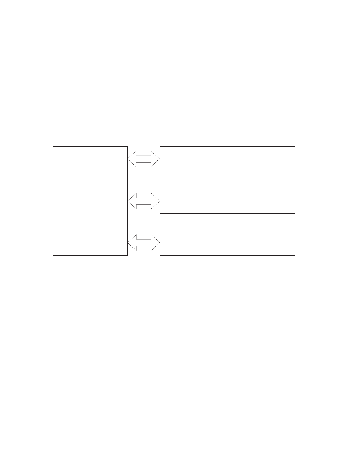
Major product systems
The product includes the following systems:
Engine control system
●
Laser/scanner system
●
Image-formation system
●
Pickup-and-feed system
●
Figure 1-1 Product systems
LASER/SCANNER SYSTEM
ENGINE CONTROL
SYSTEM
IMAGE-FORMATION SYSTEM
PICKUP-AND-FEED SYSTEM
2 Chapter 1 Theory of operation ENWW
Page 23
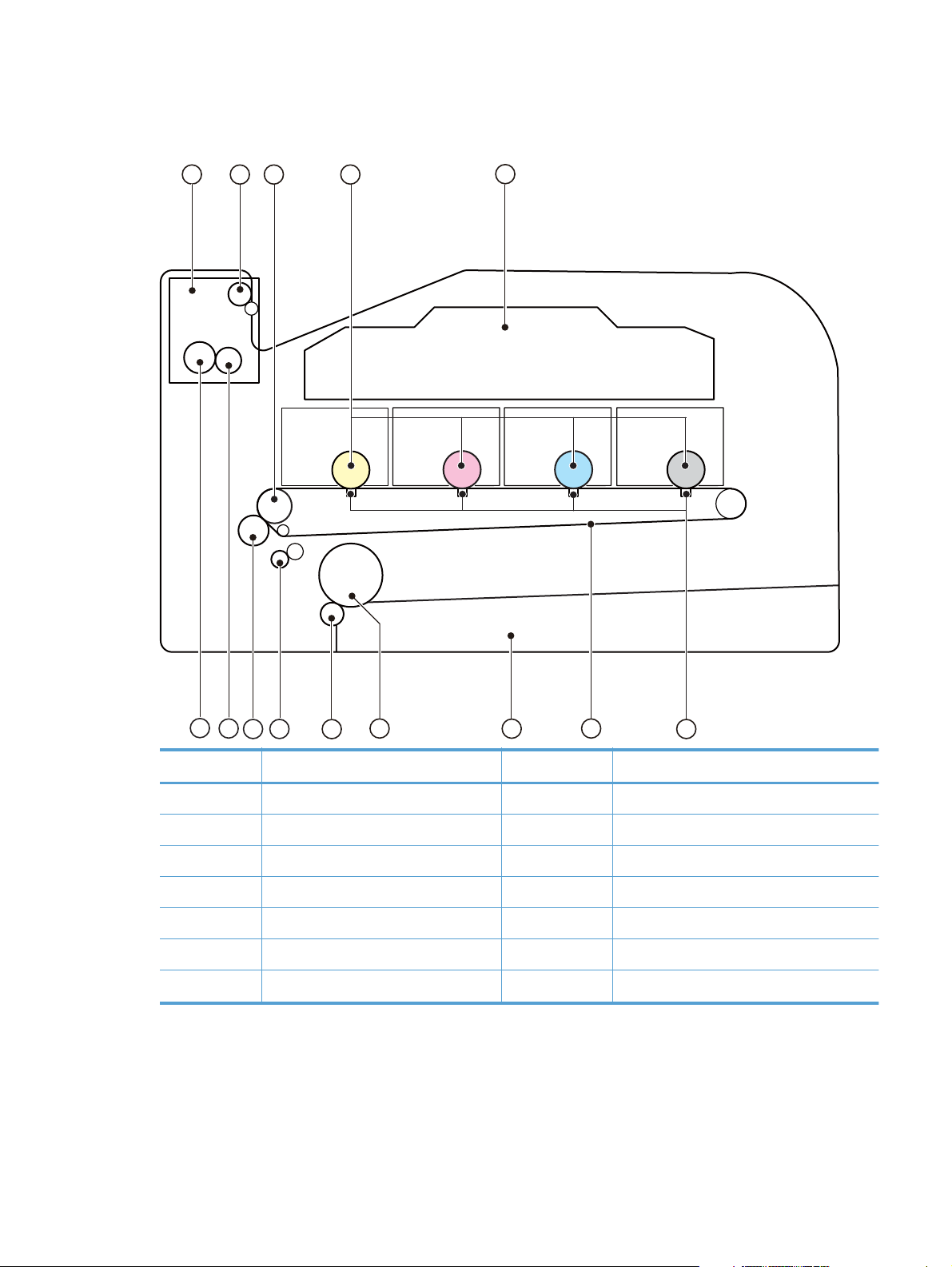
Product components
Figure 1-2 Product components
1
3 4
2
5
14
13
Item Description Item Description
1 Fuser unit 8 Cassette
2 Delivery roller 9 Pickup roller
3 ITB drive roller 10 Separation roller
4 Photosensitive drum 11 Registration roller
5 Laser scanner assembly 12 Secondary transfer roller
6 Transfer pad 13 Fusing film
7 Intermediate transfer belt (ITB) 14 Pressure roller
12
11
10
9
8
7
6
ENWW
Basic operation
3
Page 24

Sequence of operation
Table 1-1 Sequence of operation
Period Duration Purpose Remarks
WAIT From the time the power is
turned on or the door is
closed, until the printer is
ready for a print operation
STBY (Standby period) From end of the WAIT or
LSTR period until either the
print command is received
from the formatter or the
power is turned off
INTR (Initial rotation) From the time the print
command is received until the
media is picked up
PRINT From the end of INTR period
until the fuser paper sensor
detects the trailing edge of
paper
LSTR (Last rotation) From the end of the PRINT
period until the delivery motor
stops rotating
Clears the potential from the
drum surface, adjusts the
drum phase, and cleans the
ITB
Maintains the printer in
readiness for a print
command
Prepares the photosensitive
drum for printing
Forms the images on the
photosensitive drum and
transfers the toner image to
the print media
Moves the printed sheet out
of the printer
Detects the cartridge
presence and environment;
completes any required
calibration (color registration
control and image stability)
The printer enters sleep mode
when the formatter sends a
sleep command, and
performs color registration
and image stability control
when the formatter sends
those commands
Performs image stabilization
at a specified print interval or
at specified times
The printer enters the INTR
period as soon as the
formatter sends another print
command
4 Chapter 1 Theory of operation ENWW
Page 25
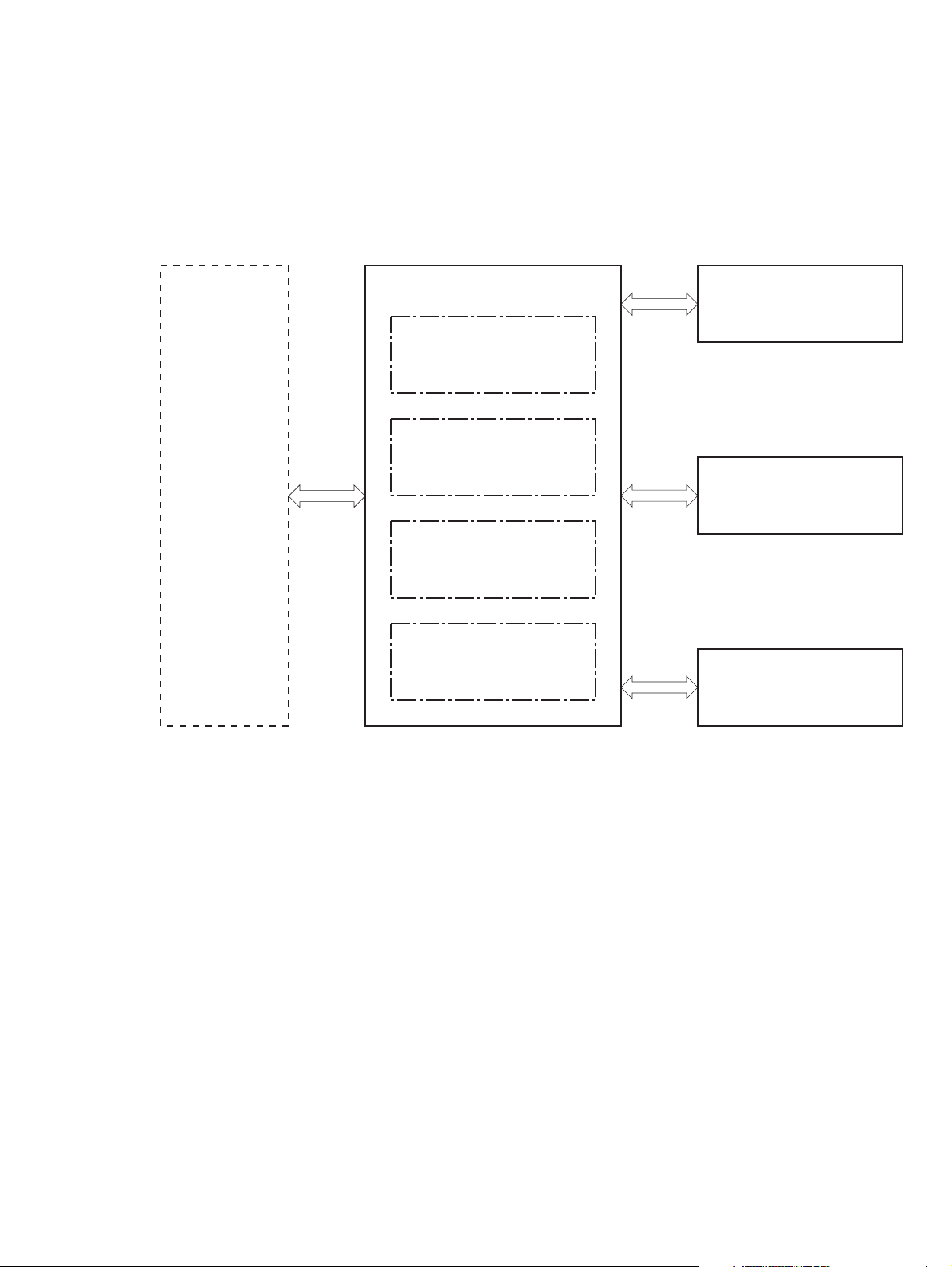
Engine control system
The engine control system coordinates all printer functions and drives the other three systems.
The engine control system contains the DC controller, high-voltage power-supply PCA, low-voltage
power-supply unit, and fuser control.
Figure 1-3 Engine control system components
Formatter
Engine-control system
Laser scanner system
DC controller
Low-voltage power supply
Image-formation system
High-voltage power supply
Fuser control
Pickup, feed and delivery
system
ENWW
Engine control system
5
Page 26
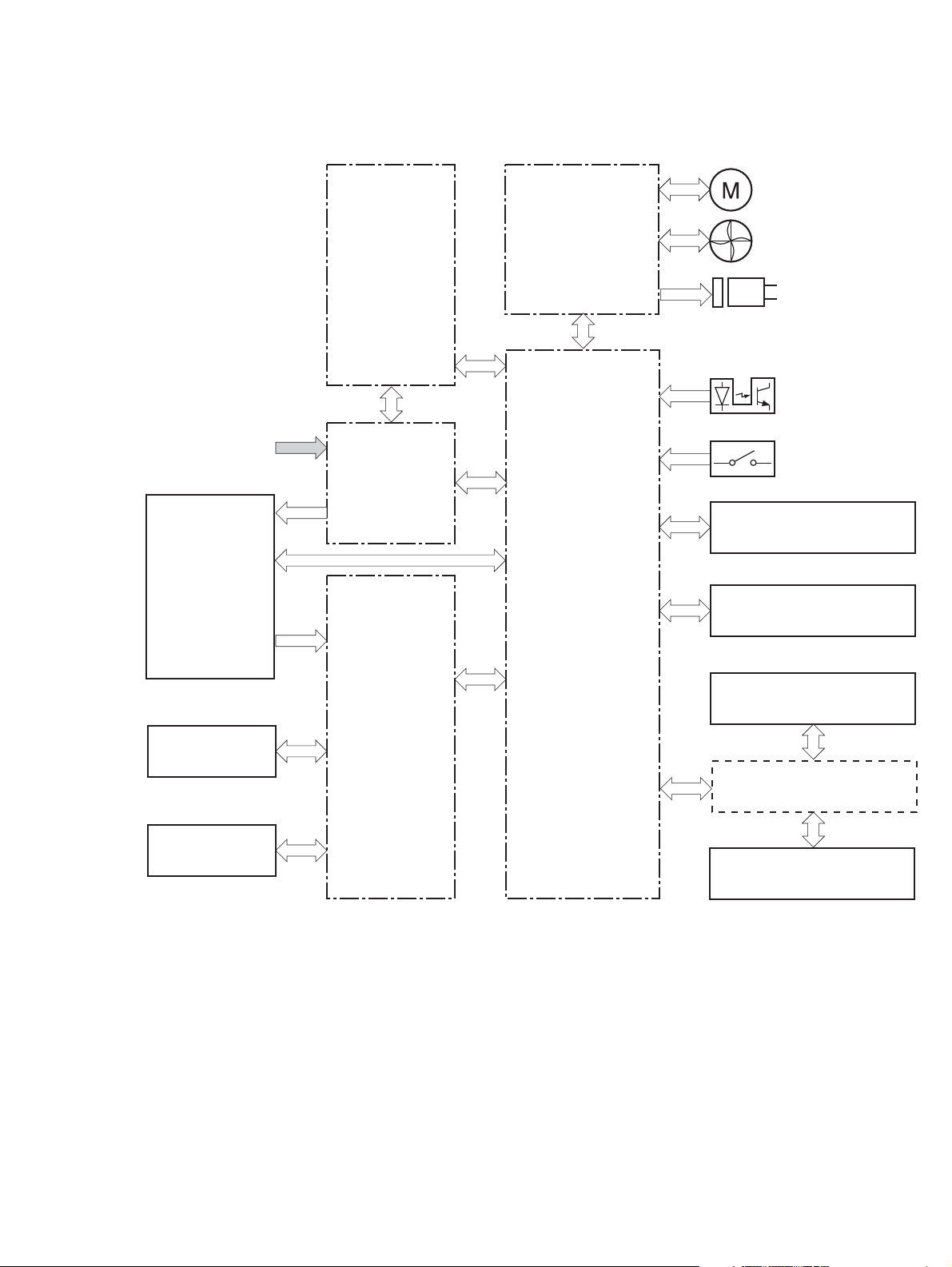
DC controller
Figure 1-4 DC controller circuit diagram
Motor
AC input
Fuser
Low-voltage
power supply
Fuser
power supply
Driver
DC controller
Fan
Solenoid
Photointerrupter
Switch
ITB assembly
Laser scanner assembly
USB (NOTE)
T2 roller
Cartridge
High-voltage
power supply
Formatter
Control panel
6 Chapter 1 Theory of operation ENWW
Page 27
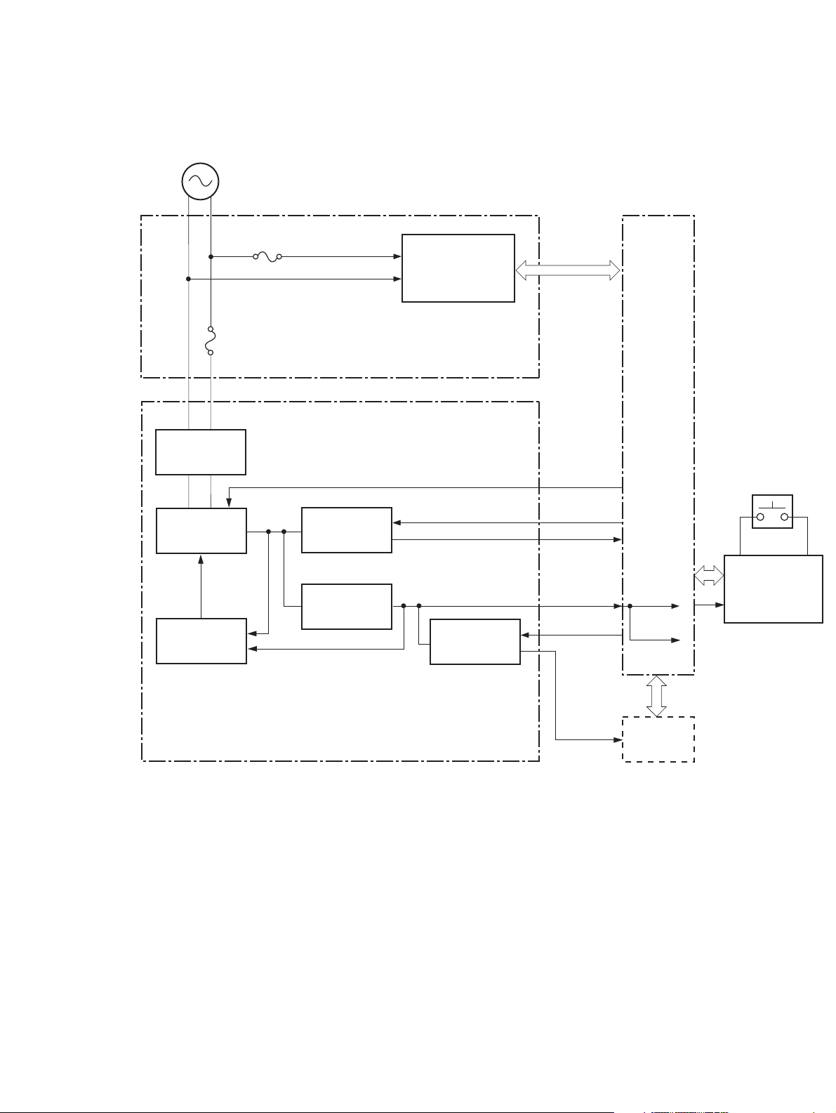
Low-voltage power supply
Figure 1-5 Low-voltage power supply
AC input
Fuse
FU901
Fuse
FU801
Rectifying
circuit
Fuser control
circuit
Fuser power supply
PWSV
DC controller
Power switch
SW801
+24V
generation
circuit
Protection
circuit
+24VR
+24V
control circuit
+3.3V
generation
circuit
+3.3V
control circuit
Low-voltage power supply
REM24V
+24VA
VCTRLOFF
+3.3VC
+3.3VA+3.3VA
+3.3VB
Formatter
+24VA
Power switch
control circuit
ENWW
Engine control system
7
Page 28
High-voltage power supply
Figure 1-6 High-voltage power supply
Primary charging bias circuit
Cartridge
Photosensitive drum
T1 pad
ITB cleaning
ass’y
T2 roller
Developing bias circuit
ITB
ITB cleaning brush
bias circuit
ITB cleaning roller
bias circuit
T2 bias circui
DC controller
T1 bias circuit
High-voltage power supply
8 Chapter 1 Theory of operation ENWW
Page 29
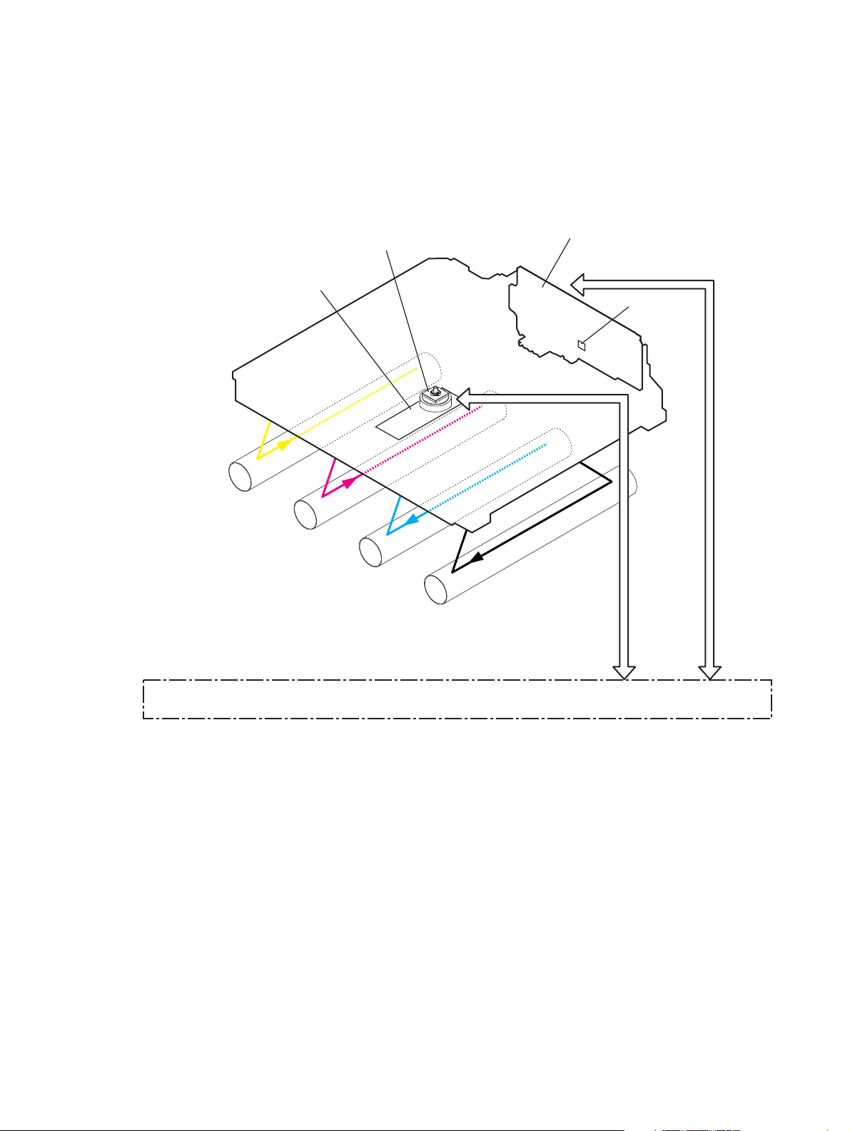
Laser/scanner system
The formatter sends video signals to the DC controller, which controls the laser/scanner. When the
laser/scanner system receives those signals, it converts them to latent images on the photosensitive
drum.
Figure 1-7 Laser/scanner system
Scanner mirror
Scanner motor assembly
Laser assembly
BD sensor
Photosensitive drum
(Y)
Photosensitive drum
(M)
Photosensitive drum
Laser failure detection
The optical unit failure detection sensor manages the laser/scanner unit failure-detection functions. The
DC controller identifies the laser/scanner unit failure and notifies the formatter if the laser/scanner unit
encounters the following conditions:
Scanner motor failure
●
BD failure
●
(C)
Photosensitive drum
(K)
DC controller
ENWW
Laser/scanner system
9
Page 30

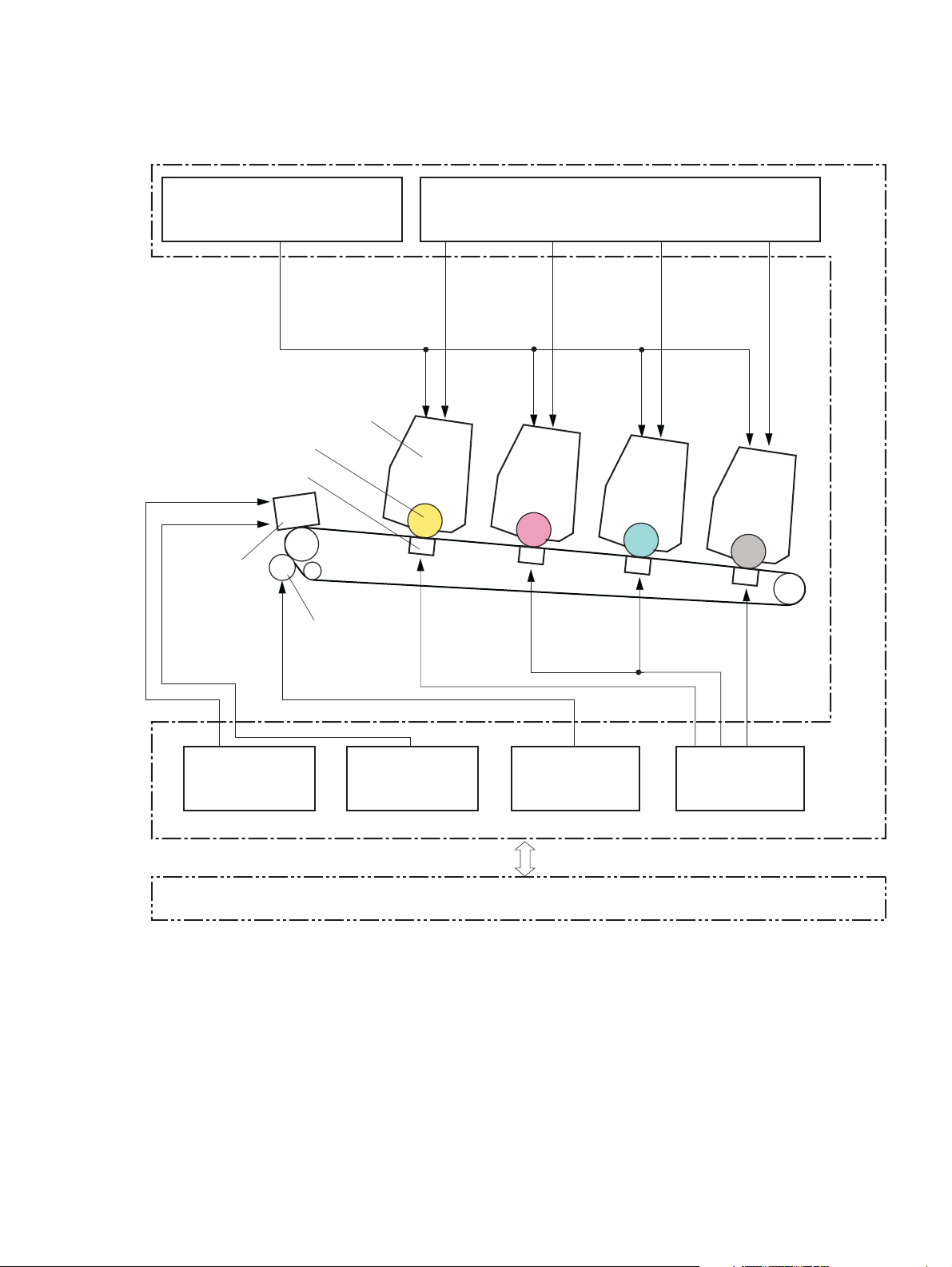
Image-formation system
The image-formation system forms a toner image on media. The product includes four toner cartridges
that contain the toner. Toner is applied in the following order, using only the colors necessary for a
specific image: yellow (Y), magenta (M), cyan (C), and black (K).
Figure 1-8 Image-formation system
High-voltage power supply
Fuser
DC controller
Laser scanner assembly
Cartridge
T2 roller
Image-formation process
Laser printing requires the interaction of several different technologies including electronics, optics, and
electrographics to provide a printed page. Each process functions independently and must be
coordinated with the other processes. Image formation consists of the following processes:
Latent-image formation
●
Development
●
Transfer
●
MCYK
T1 pad
Photosensitive drum
ITB
10 Chapter 1 Theory of operation ENWW
Page 31

Fuser
●
ITB cleaning
●
Drum cleaning
●
These processes are divided into nine steps, which are shown in
on page 11 and described in the following sections.
Figure 1-9 Image-formation process
Delivery
Latent image formation
7. Fusing
Fuser
3. Development
Development
Transfer
6. Separation
5. Secondary transfer
Registration
2. Laser beam exposure
1. Primary charging
Photosensitive drum cleaning
9. Drum cleaning
4. Primary transfer
8. ITB cleaning
ITB cleaning
Figure 1-9 Image-formation process
: Media path
: Direction of drum rotation
: Block
: Step
Pickup
Latent-image formation stage
During the two steps that comprise this stage, a latent image is formed by applying a negative charge
to the photosensitive drum. You cannot see this image on the drum.
ENWW
Image-formation system
11
Page 32

Step 1: primary charging
A high-voltage DC bias is applied to the primary charging roller, which is made of conductive rubber
and is in contact with the drum surface. As the roller moves across the drum, it applies the negative
charge to that surface.
Figure 1-10 Primary charging
Primary charging roller
Photosensitive drum
Step 2: laser-beam exposure
The laser beam scans the photosensitive drum to neutralize the negative charge on portions of the drum
surface. An electrostatic latent image is formed where the negative charge was neutralized.
DC bias
Figure 1-11 Laser-beam exposure
Unexposed area Exposed area
Developing stage
The developer roller comes in contact with the photosensitive drum and deposits toner on the
electrostatic latent image.
Laser beam
12 Chapter 1 Theory of operation ENWW
Page 33

Step 3: development
Toner acquires a negative charge as a result of the friction from the developer roller rotating against the
developer blade. When the negatively charged toner comes in contact with the drum, it adheres to the
electrostatic latent image. When the toner is on the drum, the image becomes visible.
Figure 1-12 Development
Developer blade
Exposed area
Unexposed area
Developer roller
DC negative bias
Unexposed area
Exposed area
Photosensitive drum
ENWW
Image-formation system
13
Page 34

Transfer stage
Step 4: primary transfer
The toner image on the photosensitive drum is transferred to the ITB. The DC positive bias is applied to
the primary transfer pad. The negatively charged toner transfers to the ITB from the drum surface.
Figure 1-13 Primary transfer
Photosensitive
T1 pad
drum
ITB
T1 bias
Step 5: secondary transfer
The toner image on the ITB is transferred to the print media. The DC positive bias is applied to the
secondary transfer roller. As the media passes between the secondary transfer roller and the ITB, the
toner image is transferred to the media.
Figure 1-14 Secondary transfer
Media
Secondary transfer roller
DC bias
ITB
ITB drive roller
14 Chapter 1 Theory of operation ENWW
Page 35

Step 6: separation from the ITB
The elasticity of the print media and the curvature of the ITB drive roller cause the media to separate
from the ITB.
Figure 1-15 Separation from the ITB
Media
Secondary transfer roller
Fusing stage
Until the fusing stage is complete, the image is not permanently affixed to the print media. The toner
can be easily smudged until the heat and pressure of the fusing process fix the image to the sheet.
Step 7: fusing
ITB
ITB drive roller
The product uses an on-demand fixing method to fix the toner image onto the media. The toner image
is permanently affixed to the print media by heat and pressure.
Figure 1-16 Fusing
Fuser film
Fuser heater
Toner
Paper
Pressure roller
ENWW
Image-formation system
15
Page 36

ITB cleaning stage
Step 8: ITB cleaning
The ITB cleaning roller and the cleaning brush are applied with the DC positive bias to charge the
residual toner positive. Because the primary transfer pad is also applied with the DC positive bias, the
positively charged residual toner is reverse-transferred to the photosensitive drum from the ITB surface.
Figure 1-17 ITB cleaning
Positive potential waste toner
Negative potential waste toner
Partition sheet
ITB cleaning brush
Sweeper strip
DC bias
Cartridge
Photosensitive drum
ITB cleaning roller
IT B
DC bias
16 Chapter 1 Theory of operation ENWW
Page 37

Drum cleaning stage
Not all of the toner is removed from the photosensitive drum during the transfer stage. During the
cleaning stage, the residual, or waste, toner is cleared from the drum surface to prepare the surface for
the next latent-image formation.
Step 9: drum cleaning
The cleaning blade scrapes the residual toner off the surface of the photosensitive drum and deposits it
in the waste-toner container. The drum is now clear and is ready for the next image-formation process.
Figure 1-18 Drum cleaning
Cleaning blade Blowout seal
Photosensitive
drum
ENWW
Image-formation system
17
Page 38

Pickup-and-feed system
The pickup-and-feed system picks up and feeds the print media. It consists of several types of feed
rollers.
Figure 1-19 Pickup-and-feed system
SR610 SR611
SR609
SR607
SR603
SR602
SR601
Number Description Number Description
Cassette paper out sensor SR601 CASSETTE PAPER OUT signal
Registration sensor SR602 REGISTRATION signal
Loop sensor SR603 LOOP signal
SW1
Fuser output sensor SR609 FUSER OUTPUT signal
Rear door open detection sensor SR607 REAR DOOR OPEN DETECTION signal
Paper width sensor (L) SR610 PAPER WIDTH (L) signal
Paper width sensor (R) SR611 PAPER WIDTH (R) signal
Front door open detection switch SW1 FRONT DOOR OPEN DETECTION signal
18 Chapter 1 Theory of operation ENWW
Page 39

Jam detection
The product uses the following sensors to detect the presence of media and to check whether media is
being fed correctly or has jammed:
Cassette media-presence sensor
●
Top-of-page sensor
●
Loop sensor
●
Fuser delivery sensor
●
The product detects the following jams:
Pickup delay jam
●
Pickup stationary jam
●
Delivery delay jam
●
Delivery stationary jam
●
Fixing wrapping jam
●
Residual media jam
●
ENWW
Pickup-and-feed system
19
Page 40

Scanner system (base models)
The flatbed image scanner captures an electronic image of the document on the glass. The scanner
does this by illuminating the document with LEDs (red, green, and blue) and capturing the image in the
image sensor to create an electronic format of the document. The flatbed scanner consists of three main
elements
CIS scanner. The CIS (contact image sensor) scanner captures an image using the product's
●
optical path. Red, green, and blue LEDs sequentially illuminate a small strip of the document (often
called a raster line), and the optical system captures each color in a single row of CCD sensors
that cover the entire page width. Because only one color is captured for each line per exposure,
the three colors are recombined electronically to create the full color image. For monochromatic
scans or copies, all three LEDs are illuminated to create a white light for the scan so the raster line
can be captured in one exposure.
Mechanical carriage drive. The carriage drive moves the CIS scan head along the document
●
length to create the image. In this product, a small DC motor with an optical encoder creates this
motion. The speed of the carriage drive is proportional to the scan resolution (300 ppi is much
faster than 1200 ppi) and also proportional to the type of scan (color scans are three-times slower
than monochromatic scans). A 1200 ppi color scan moves so slowly that the product may appear
to not be working, whereas a monochromatic copy scan moves at 50 times that speed and will be
somewhat noisy.
Image processing system (formatter). The formatter processes the scanner data into either
●
a copy or a scan to the computer. For copies, the image data is sent directly to the product
without being transmitted to the computer. Depending on user selections for the copy settings, the
formatter enhances the scanner data significantly before sending it to the product. Image data is
captured at 300 ppi for copies and is user selectable for scans to the computer. Each pixel is
represented by 8 bits for each of the three colors (256 levels for each color), for a total of 24 bits
per pixel (24-bit color).
Scanner power-on sequence of events
When the product is turned on, it performs the following tests:
Motor test. The product moves the motor left and right to confirm operation. It reports a scanner
●
error 12 if no motion is detected in the motor encoder system.
Wall find. The scan carriage moves slowly to the left while watching an encoder on the carriage
●
motor to determine when the carriage has found the side wall or stop. This enables the product to
identify the document origin (position of the original). If the document origin cannot be located, a
default position is used instead.
LED check. The product moves the carriage to the white calibration label under the left side of
●
the flatbed image scanner, and it verifies that the minimum and maximum response is acceptable.
It reports a scanner error 14 if the response is unacceptable.
Home find. The scan carriage uses the optical scanner to find physical reference features that
●
relate to the document origin at the left side of the image glass. This process ensures accurate
location of the first document pixels so that the user documents will have an accurate placement of
20 Chapter 1 Theory of operation ENWW
Page 41

the image on scans and copies. It reports a scanner error 6 message if the reference features are
not found.
Calibration. This test, also known as scanner color calibration, enables the product to identify
●
the black and white on every pixel in the CCD. Calibration occurs in two major processes: a
broad (analog) adjustment of all pixels to bring them into the target output range, and a pixel-bypixel adjustment (digital) to fine tune the actual black and white response. The calibration process
occurs under the left side of flatbed image scanner where there is a special white calibration
label.
Calibration is the most important step in creating a high quality image. Calibration problems can
include color and brightness inaccuracies, and vertical streaks through the image. The calibration
process identifies any bad pixels and enables the image formatter to recreate the lost information
from adjacent pixels. Extreme cases of this problem can appear as large vertical streaks or image
smears. The user has no control over the calibration process itself or this pixel-replacement
process.
Copy or scan-to-computer sequence of events
To create an accurate rendition of a document, the scanner must be calibrated for the requested
operation. If the user selects a scan at 600 ppi color, the flatbed image scanner calibrates for that
specific operational mode. Subsequently, the flatbed image scanner automatically re-calibrates for the
next requested operation. Calibration does not occur for every new copy request.
Normal sequence of operation for a flatbed copy or scan includes:
1. LEDs illuminate.
2. Carriage motion begins moving the CIS scanner toward the right.
3. Image capture continues for the entire page or length requested in a scan-to-computer operation.
4. Carriage returns to the home position on the left.
ENWW
Scanner system (base models)
21
Page 42

Fax functions and operation (fax models only)
The following sections describe the product fax capabilities.
Computer and network security features
The product can send and receive fax data over telephone lines that conform to public switch telephone
network (PSTN) standards. The secure fax protocols make it impossible for computer viruses to be
transferred from the telephone line to a computer or network.
The following product features prevent virus transmission:
No direct connection exists between the fax line and any devices that are connected to the USB or
●
Ethernet ports.
The internal firmware cannot be modified through the fax connection.
●
All fax communications go through the fax subsystem, which does not use Internet data-exchange
●
protocols.
PSTN operation
The PSTN operates through a central office (CO) that generates a constant voltage on the TIP and RING
wires (48 V, usually). A device goes on-hook by connecting impedance (such as 600 ohms for the
U.S.) across the TIP and RING so that a line current can flow. The CO can detect this current and can
send impulses like dial tones. The product generates more signaling tones, such as dialing digits, to tell
the CO how to connect the call. The product can also detect tones, such as a busy tone from the CO,
that tell it how to behave.
When the call is finally connected, the CO behaves like a piece of wire connecting the sender and
receiver. This is the period during which all of the fax signaling and data transfer occurs. When a call
is completed, the circuit opens again and the line-current flow ceases, removing the CO connection
from both the sender and the receiver.
On most phone systems, the TIP and RING signals appear on pins 3 and 4 of the RJ-11 modular jack
(the one on the fax card, as defined in the common 6 wire RJ standard). These two signals do not have
to be polarized because all of the equipment works with either TIP or RING on one pin and the other
signal on the other pin. This means that cables of either polarity can interconnect and still work.
These basic functions of PSTN operation are assumed in the design of the fax subsystem. The product
generates and detects the signaling tones, currents, and data signals that are required to transmit and
receive faxes using the PSTN.
Receive faxes when you hear fax tones
In general, incoming faxes to the product are automatically received. However, if other devices are
connected to the same phone line, the product might not be set to answer automatically.
22 Chapter 1 Theory of operation ENWW
Page 43

If the product is connected to a phone line that receives both fax and phone calls, and you hear fax
tones when you answer the extension phone, receive the fax in one of two ways:
If you are near the product, press Start Fax on the control panel.
●
Press 1-2-3 in sequence on the extension phone keypad, listen for fax transmission sounds, and
●
then hang up.
NOTE: In order for the 1-2-3 sequence to work, the extension phone setting must be set to On in the
Fax Setup menu.
Distinctive ring function
Distinctive ring is a service that a telephone company provides. The distinctive ring service allows three
phone numbers to be assigned to one phone line. Each phone number has a distinctive ring. The first
phone number has a single ring, the second phone number has a double ring, and the third phone
number has a triple ring.
NOTE: The product has not been tested with all of the distinctive-ring services that telephone
companies provide in all countries/regions. HP does not guarantee that the distinctive-ring function will
operate correctly in all countries/regions. Contact the local phone service provider for assistance.
Set up the distinctive ring function
1. Press Setup
2. Use the arrow buttons to select Fax Setup, and then press Enter.
3. Use the arrow buttons to select Basic Setup, and then press Enter.
4. Use the arrow buttons to select Distinctive Ring, and then press Enter.
5. Use the arrow buttons to select one of the following options:
NOTE: The control-panel display might show some of these options as abbreviations.
All Rings (default setting)
●
Single
●
Double
●
Triple
●
Double and Triple
●
Press Enter to save the setting.
.
Fax by using Voice over IP services
ENWW
Voice over IP (VoIP) services provide normal telephone service, including long distance service through
a broadband Internet connection. These services use packets to break up the voice signal on a
telephone line and transmit it digitally to the receiver, where the packets are reassembled. The VoIP
Fax functions and operation (fax models only)
23
Page 44

services are often not compatible with fax machines. The VoIP provider must state that the service
supports fax over IP services.
Because the installation process varies, the VoIP service provider will have to assist in installing the
product fax component.
Although a fax might work on a VoIP network, it can fail when the following events occur:
Internet traffic becomes heavy and packets are lost.
●
Latency (the time it takes for a packet to travel from its point of origin to its point of destination)
●
becomes excessive.
If you experience problems using the fax feature on a VoIP network, ensure that all of the product
cables and settings are correct. Configuring the Fax Speed setting to Medium(V.17) or Slow(V.
29) can also improve your ability to send a fax over a VoIP network.
If you continue to have problems faxing, contact your VoIP provider.
The fax subsystem
The formatter, fax card, firmware, and software all contribute to the fax functionality. The designs of the
formatter and fax card, along with parameters in the firmware, determine the majority of the regulatory
requirements for telephony on the product.
The fax subsystem is designed to support V.34 fax transmission, low speeds (such as V.17 fax), and
older fax machines.
Fax card in the fax subsystem
Two versions of the fax card are used in the product. One is used in the North American, South
American, and Asian countries/regions. The other is used primarily in European countries/regions.
The fax card contains the modem chipset (DSP and CODEC) that controls the basic fax functions of tone
generation and detection, along with channel control for fax transmissions. The CODEC and its
associated circuitry act as the third-generation silicon data access arrangement (DAA) to comply with
worldwide regulatory requirements.
The only difference between the two versions is that each version is compliant with the 2/4-wire phone
jack system from the respective country/region.
Safety isolation
The most important function of the fax card is the safety isolation between the high-voltage, transientprone environment of the telephone network (TNV [telephone network voltage]) and the low-voltage
analog and digital circuitry of the formatter (SELV [secondary extra-low voltage]). This safety isolation
provides both customer safety and product reliability in the telecom environment.
Any signals that cross the isolation barrier do so magnetically. The breakdown voltage rating of barriercritical components is greater than 5 kV.
24 Chapter 1 Theory of operation ENWW
Page 45

Safety-protection circuitry
In addition to the safety barrier, the fax card protects against over-voltage and over-current events.
Telephone over-voltage events can be either differential mode or common mode. The event can be
transient in nature (a lightning-induced surge or ESD) or continuous (a power line crossed with a phone
line). The fax card protection circuitry provides margin against combinations of over-voltage and overcurrent events.
Common mode protection is provided by the selection of high-voltage-barrier critical components
(transformer and relay). The safety barrier of the fax card PCB traces and the clearance between the
fax card and surrounding components also contribute to common mode protection.
A voltage suppressor (a crowbar-type thyristor) provides differential protection. This device becomes
low impedance at approximately 300 V differential, and crowbars to a low voltage. A series thermal
switch works in conjunction with the crowbar for continuous telephone line events, such as crossed
power lines.
All communications cross the isolation barrier magnetically. The breakdown voltage rating of barriercritical components is greater than 5 kV.
Data path
TIP and RING are the two-wire paths for all signals from the telephone network. All signaling and data
information comes across them, including fax tones and fax data.
The telephone network uses DC current to determine the hook state of the telephone, so line current
must be present during a call. The silicon DAA provides a DC holding circuit to keep the line current
constant during a fax call.
The silicon DAA converts the analog signal to a digital signal for DSP processing, and also converts the
digital signal to an analog signal for transmitting data through a telephone line.
The magnetically coupled signals that cross the isolation barrier go through either a transformer or a
relay.
The DSP in the fax card communicates with the ASIC in the formatter using the high-speed serial
interface.
Hook state
Another magnetically coupled signal is the control signal that disconnects the downstream telephone
devices (such as a phone or answering machine). A control signal originating on the DSP can change
the relay state, causing the auxiliary jack (downstream jack) to be disconnected from the telephone
circuit.
The product takes control of calls that it recognizes as fax calls. If the product does not directly pick up
the call, it monitors incoming calls for the fax tone or for the user to direct it to receive a fax. This idle
mode is also called eavesdropping. This mode is active when the product is on-hook but current exists
in the downstream phone line because another device is off-hook. During eavesdropping, the receive
circuit is enabled but has a different gain from the current that is generated during normal fax
transmissions.
ENWW
Fax functions and operation (fax models only)
25
Page 46

The product does not take control of the line unless it detects a fax tone or the user causes it to connect
manually. This feature allows the user to make voice calls from a phone that is connected to the product
without being cut off if a fax is not being received.
Downstream device detection
The line voltage monitoring module of the silicon DAA can detect the line state as well as the
downstream device. It tells DSP via DIB that an active device (telephone, modem, or answering
machine) is connected to the auxiliary port on the product (the right side of the dual RJ-11 jack). The
DSP uses the signal to ensure that the product does not go off-hook (and disconnects a downstream
call) until it has been authorized to do so (by a manual fax start or the detection of the appropriate
tones).
Hook switch control
In the silicon DAA the CODEC controls the hook switch directly. The CODEC is activated when it
receives commands from the DSP. When the circuit is drawing DC current from the central office it is
considered off-hook. When no DC current flows the state is considered on-hook.
Ring detect
Ring detect is performed by the line voltage monitoring module of the silicon DAA, and is a
combination of voltage levels and cadence (time on and time off). Both must be present to detect a
valid ring. The CODEC works with DSP as well as the firmware to determine if an incoming signal is an
answerable ring.
Line current control
The DC current from the CO needs to have a path to flow from TIP to RING. The DC impedance
emulation line modulator and DC terminations modules in the silicon DAA act as a DC holding circuit,
and work with the firmware to achieve the voltage-current characteristic between TIP and RING. The
impedance (the current-voltage characteristic) changes corresponding to certain special events, such as
pulse dialing or when the product goes on-hook.
Billing- (metering-) tone filters
Switzerland and Germany provide high-frequency AC signals on the phone line in order to bill
customers.
A filter in a special fax cable (for certain countries/regions), can filter these signals. Because these
billing signals are not used in the U.S., these filters are not present in the U.S. fax cable.
To obtain a special fax cable, contact your local telephone service provider.
Fax page storage in flash memory
Fax pages are the electronic images of the document page. They can be created in any of three ways:
scanned to be sent to another fax machine, generated to be sent by the computer, or received from a
fax machine to be printed.
26 Chapter 1 Theory of operation ENWW
Page 47

The product stores all fax pages in flash memory automatically. After these pages are written into flash
memory, they are stored until the pages are sent to another fax machine, printed on the product,
transmitted to the computer, or erased by the user.
These pages are stored in flash memory, which is the nonvolatile memory that can be repeatedly read
from, written to, and erased. The product has 8 MB of flash memory, of which 7.5 MB is available for
fax storage. The remaining 0.5 MB is used for the file system and reclamation. Adding RAM does not
affect the fax page storage because the product does not use RAM for storing fax pages.
Stored fax pages
The user can reprint stored fax receive pages in case of errors. For a fax send, the product will resend
the fax in case of errors. The product will resend stored fax pages after a busy signal, communication
error, no answer, or power failure. Other fax devices store fax pages in either normal RAM or shortterm RAM. Normal RAM immediately loses its data when power is lost, while short-term RAM loses its
data about 60 minutes after power failure. Flash memory maintains its data for years without any
applied power.
Advantages of flash memory storage
Fax pages that are stored in flash memory are persistent. They are not lost as a result of a power
failure, no matter how long the power is off. Users can reprint faxes in case the print cartridge runs out
of toner or the product experiences other errors while printing faxes.
The product also has scan-ahead functionality that makes use of flash memory. Scan-ahead
automatically scans pages into flash memory before a fax job is sent. This allows the sender to pick up
the original document immediately after it is scanned, eliminating the need to wait until the fax
transmission is complete.
Because fax pages are stored in flash memory rather than RAM, more RAM is available to handle
larger and more complicated copy and print jobs.
ENWW
Fax functions and operation (fax models only)
27
Page 48

USB Flash Drive
This product features printing the following types of files from the USB flash drive.
PDF
●
RGB JPEG
●
When a USB flash drive is inserted into the front of the product, the control panel will display the USB
Flash Drive Menu. The files present on the USB flash drive can be accessed from the control panel using
the touch screen. Any RGB jpeg or pdf files on the USB flash drive can be printed directly from the
product control panel. Pages also can be scanned and saved to the USB flash drive from the control
panel.
28 Chapter 1 Theory of operation ENWW
Page 49

2 Solve problems
Solve problems checklist
●
Menu map
●
Troubleshooting process
●
Tools for troubleshooting
●
Clear jams
●
Solve paper-handling problems
●
Solve image quality problems
●
Solve performance problems
●
Solve product connectivity problems
●
Service mode functions
●
Solve fax problems
●
Product updates
●
ENWW 29
Page 50

Solve problems checklist
1. Ensure that the product is set up correctly.
a. Press the power button to turn on the product or to deactivate the Auto-Off mode.
b. Check the power-cable connections.
c. Ensure that the line voltage is correct for the product power configuration. (See the label that
is on the back of the product for voltage requirements.) If you are using a power strip and its
voltage is not within specifications, plug the product directly into the wall. If it is already
plugged into the wall, try a different outlet.
2. Check the cable connections.
a. Check the cable connection between the product and the computer. Ensure that the
connection is secure.
b. Ensure that the cable itself is not faulty, by using a different cable if possible.
c. Check the network connection: Ensure the network light is lit. The network light is next to the
network port on the back of the product.
If the product remains unable to connect to the network, uninstall and then reinstall the
product. If the error persists, contact a network administrator.
3. Check to see if any messages appear on the control panel.
4. Ensure that the paper you are using meets specifications.
5. Ensure that the paper is loaded correctly in the input tray.
6. Ensure that the product software is installed correctly.
7. Verify that you have installed the printer driver for this product, and that you are selecting this
product from the list of available printers.
8. Print a configuration page.
a. If the page does not print, verify that the input tray contains paper and that the paper is
properly loaded.
b. Ensure that the toner cartridge is installed correctly.
30 Chapter 2 Solve problems ENWW
Page 51

c. If the page jams in the product, clear the jam.
d. If the print quality is unacceptable, complete the following steps:
Verify that the print settings are correct for the paper you are using.
●
Solve print-quality problems.
●
9. Print a small document from a different program that has printed in the past. If this solution works,
then the problem is with the program you are using. If this solution does not work (the document
does not print), complete these steps:
a. Try printing the job from another computer that has the product software installed.
b. Check the cable connection. Direct the product to the correct port, or reinstall the software,
selecting the connection type you are using.
ENWW
Solve problems checklist
31
Page 52

Menu map
Use the following procedure to print a control-panel menu layout map.
1. From the Home screen, touch the Setup
2. Touch the Reports button.
3. Touch the Menu Structure button.
Troubleshooting process
When the product malfunctions or encounters an unexpected situation, the product control panel alerts
you to the situation. This chapter contains information to help diagnose and solve problems.
Use the pre-troubleshooting checklist to evaluate the source of the problem and to reduce the
●
number of steps that are required to fix the problem.
Use the troubleshooting flowchart to pinpoint the root cause of the hardware malfunction. The
●
flowchart guides you to the section of this chapter that contains steps for correcting the
malfunction.
Before beginning any troubleshooting procedure, check the following issues:
Are supply items within their rated life?
●
Does the configuration page reveal any configuration errors?
●
button.
NOTE: The customer is responsible for checking supplies and for using supplies that are in good
condition.
Pre-troubleshooting checklist
The following table includes basic questions to ask the customer to quickly help define the problem(s).
General topic Questions
Environment
●
●
●
●
●
●
Is the product installed on a solid, level surface (+/- 1°)?
Is the power-supply voltage within ± 10 volts of the specified power source?
Is the power-supply plug inserted in the product and the outlet?
Is the operating environment within the specified parameters?
Is the product exposed to ammonia gas, such as that produced by diazo
copiers or office cleaning materials?
NOTE: Diazo copiers produce ammonia gas as part of the copying
processes. Ammonia gas (from cleaning supplies or a diazo copier) can have
an adverse affect on some product components (for example, the printcartridge OPC).
Is the product exposed to direct sunlight?
32 Chapter 2 Solve problems ENWW
Page 53

General topic Questions
Media
Input trays
Toner cartridges
Transfer unit and fuser
Covers
Condensation
Miscellaneous
Does the customer use only supported media?
●
Is the media in good condition (no curls, folds, or distortion)?
●
Is the media stored correctly and within environmental limits?
●
Is the amount of media in the tray within specifications?
●
Is the media correctly placed in the tray?
●
Are the paper guides aligned with the stack?
●
Is the cassette correctly installed in the product?
●
Is each toner cartridge installed correctly?
●
Are the transfer unit and fuser installed correctly?
●
Is the front cover closed?
●
Does condensation occur following a temperature change (particularly in
●
winter following cold storage)? If so, wipe affected parts dry or leave the
product on for 10 to 20 minutes.
Was the toner cartridge opened soon after being moved from a cold to a
●
warm room? If so, allow the toner cartridge to sit at room temperature for 1 to
2 hours.
Check for and remove any non-HP components (toner cartridges, memory
●
modules, and EIO cards) from the product.
If the hardware or software configuration has not changed or the problem is
●
not associated with any specific software, see the complete service manual for
this product.
Remove the product from the network and ensure that the failure is associated
●
with the product before beginning troubleshooting.
For any print-quality issues, calibrate the product.
●
ENWW
Troubleshooting process
33
Page 54

Power-on checks
When you turn on the product, if it does not make any sound or if the control-panel display is blank,
check the following items:
Verify that the product is plugged directly into an active electrical outlet that has the correct
●
voltage. Do not plug the product into a surge protector or power strip.
Press the power button.
●
Verify that the formatter is seated and operating correctly.
●
Remove any HP Jetdirect accessories or other devices, and then try to turn the product on again.
●
Ensure that the control-panel display is connected.
●
Check the two fuses on the power supply.
●
If necessary, replace the power supply.
●
If necessary, replace the DC controller.
●
34 Chapter 2 Solve problems ENWW
Page 55

Tools for troubleshooting
Component diagnostics
LED diagnostics
Network LEDs
The onboard network solution has two network port LEDs. When the product is connected to a properly
working network through a network cable, the yellow LED indicates network activity, and the green LED
indicates the link status. A blinking yellow LED indicates network traffic. If the green LED is off, a link
has failed.
For link failures, check all of the network cable connections. In addition, you can try to manually
configure the link settings on the onboard network solution by using the product control-panel menus.
1. Touch the Setup
button.
2. Scroll to and touch the Network Setup menu.
3. Touch the Link Speed menu.
4. Select one of the following options.
Setting Description
Automatic The print server automatically configures itself for the highest link speed and
communication mode allowed on the network.
10T Half 10 megabytes per second (Mbps), half-duplex operation
10T Full 10 Mbps, full-duplex operation
100TX Half 100 Mbps, half-duplex operation
100TX Full 100 Mbps, full-duplex operation
5. Touch the OK button. The product turns off and then on.
ENWW
Tools for troubleshooting
35
Page 56

Control panel LEDs
The state of the Ready light and the Attention light on the product signal the product status. The
following table outlines the possible control-panel light states.
NOTE: Wireless models have a blue LED that illuminates when the product wireless function is
enabled and available.
Product state Ready light state Attention light state
Initializing Blinking Blinking
Ready On Off
Receiving data/processing job or
cancelling job
Error message Off Blinking
Fatal error (49 or 79 error)
1
The product restarts after one of these errors occurs.
1
Blinking Off
On On
36 Chapter 2 Solve problems ENWW
Page 57

Control-panel diagnostics
The product includes diagnostic tests for the control panel.
Test the control-panel display
1. Touch the Setup
2. Touch the left arrow button
3. Touch the Setup
4. Open the 2ndary Service menu.
5. Open the Display test menu.
Test the control-panel buttons
1. Touch the Setup
2. Touch the left arrow button
3. Touch the Setup
4. Open the 2ndary Service menu.
5. Open the Button test menu.
Engine Diagnostics
Engine test
button.
, and then quickly touch the Cancel button.
button to return to the main menus.
button.
, and then quickly touch the Cancel button.
button to return to the main menu.
1. With the product off, open the front and rear doors.
2. Turn the power on, and close both doors within ten seconds.
3. An engine test page (a page containing multiple horizontal colored lines) will print.
ENWW
Tools for troubleshooting
37
Page 58

Diagrams
Plug/jack locations
1
2
3
1 Network port
2 Hi-Speed USB 2.0 port
3 Fax ports
38 Chapter 2 Solve problems ENWW
Page 59

DC controller PCA
1
Figure 2-1 DC controller connectors
1313
8
J109J120
16
J124
23
22
J107
29
28
J108
27
1
26
2
J115
1
2
1
2
J126
1
2
J127
5
4
1
2
J119
14
15
J140
16
J103
16
2
1
J116
13
J104
8
9
4
2
3
1
J105
Table 2-1 DC controller connectors
Item Description
J103 Low-voltage power supply (+3.3 V)
J104 Thermistor (TH802)
J105 Fuser power supply
J107 Formatter
J108 Laser driver PCA
J109 Scanner motor (M704)
J115 High-voltage power supply
J116 Pickup assembly
Loop sensor (SR603)
●
Top-of-page sensor (SR602)
●
Cassette media present sensor (SR601)
●
ENWW
Tools for troubleshooting
39
Page 60

Table 2-1 DC controller connectors (continued)
Item Description
J119 ITB assembly density and perimeter sensors
J120 Developing home position sensor (SR606)
J124 Memory tags (e-labels)
J126 IOT
127 Flash
J130 Front door (cartridge access door) switch
J131 Power switch
J140 Motor driver
40 Chapter 2 Solve problems ENWW
Page 61

Locations of major components
Figure 2-2 Major components
2
1
3
4
6
Table 2-2 Major components
Item Description
1 Fuser power supply
5
ENWW
Tools for troubleshooting
41
Page 62

Table 2-2 Major components (continued)
Item Description
2 Fuser assembly
3 Sub-drive assembly
4 Low-voltage power suppy
5 Main drive assembly
6 ITB assembly
42 Chapter 2 Solve problems ENWW
Page 63

General timing charts
The following chart list the approximate timing for this product, specified in seconds.
Figure 2-3 Timing diagram
LSTR STBYPRINTSTBY INTR
ENWW
1 Print command
2 Cassette pickup solenoid
I. GENERAL TIMING CHART
Two consecutive prints on LTR paper
3 Registration sensor
4 Fuser output sensor
5 TOP signal
6 Scanner motor
7 Pickup motor
8 Main motor
9 Fuser motor
10 Fuser heater
11 Charging bias
12 Developer bias (Y)
Developer bias (K)
14 Developer bias (C)
13 Developer bias (M)
15
T1 bias (M and C)
T1 bias (Y)
16
17
T1 bias (K)
T2 bias
18
19
20 Main fan
21
23
22
Tools for troubleshooting
43
Page 64

General circuit diagram
Figure 2-4 Circuit diagram
M704
M
Laser driver PCA
J704
1234
2
1
4
LD4PWM
+3.3VB
SGND
VDO4
29
+24VA
/SCNDEC
/SCNACC
PGND
4321
J109
J140
21
J107_BUS[0:23]
987653214
RTC3V
/CCRT
/BD0
WAKEENG
/VDOEN
SC
SCLK
/TOP
SGND
201918
232221
171615
J901_BUS[0:23]
23
Formatter
J901
Formatter
J9999
123456
123456
J9998
USB
<MF model>
J202_BUS[0:21]
Laser scanner assembly
29
J501
J501_BUS[0:29]
9
87653
10
CNT41
CNT40
/BDI
SGND
LD3PWM
/VDO4
J107
23
13
121110
14
WAKEVC
SGND
VDO4
/VDO4
SGND
VDO3
14
13
12
11
10
987653214
Board to Board
connector
Wireless
Module
DEVSL
21
FEEDI1B
20
FEEDI0B
19
FEEDI1A
18
FEEDI0A
17
FEEDPB
16
FEEDPA
15
FEEDSL
14
FSRMPA
13
FSRMPB
12
FSRMI0A
11
FSRMI1A
10
FSRMI0B
9
FSRMI1B
8
/MAINMFG
7
/MAINMACC
6
/MAINMDEC
5
SGND
4
SGND
3
FAN_ON
2
FANLK
1
SGND
CNT31
+3.3VB
/VDO3
VDO3
29
J108
DC controller PCA
18
171615
/VDO2
VDO2
SGND
/VDO3
SGND
J905
GND
SGND
1
2
3
J408_BUS[0:21]
4
5
6
7
8
9
10
11
12
13
14
15
16
17
18
19
20
21
CNT30
J108_BUS[0:29]
VDO1
J903
J902B
26
DCLK
SGND
LD2PWM
2322212019
SGND
/VDO1
J902
J905_BUS[0:26]
412356789
GND
VSYNC
MT1MT2
HSYNC
+3.3VB
/VDO2
VDO2
10111213141516171819202122232425262728
<LCD model>
8
234
1
6
345
12
D0D1D2D3D4D5D6
GND
26
SGND
CNT121
CNT120
J903_BUS[0:8]
SGND
+3.3V
SGND
+3.3V
SGND
+3.3V
SGND
+3.3V
PGND
+24V
1011121314151617181920212223242526
GND
J906
LD1PWM
+3.3VB
412356789
5V
8
/CPRESET
7
/INT
6
CPCLK
5
CPIN
4
GND
3
3.3V
2
CPOUT
1
GND
J906_BUS[0:26]
J408
21
4th 1st
TAG
TAG4 TAG3 TAG 2
29282726252423222120191817161514131211
SGND
VDO10
/VDO10
8
7
6
5
4
J801_BUS[0:8]
3
2
1
D7
GND
1011121314151617181920212223242526
Control panel
Driver PCA
J406
12
+24VA
FEEDSL
21
SL
SL705
S8
S7
(W)
(R)
VIN
VIN
VSS3
VSS4
J124
Control panel
8
J904
(GY)
(OR)
(SB)
(Y)
(GY)
(OR)
(SB)
(Y)
(GR)
(BR)
5V
24V
NIRQ
NRESET
J407
SL706
3rd
TAG
S5S6S4
(R)
(W)
VIN
VSS2
SCLK
CPIN
56789
4
12
+24VA
DEVSL
12
SL
VSS1
J336B
J335B
J331B
J332B
J336
J335
J331
J332
J333
J334
GND
2nd
TAG TAG
S3
(W)
(R)
VIN
12345678
3.3V
CPOUT
123
J402
PGND
TAG1
S1
(W)
231
FANPWM
FANLK
321
FM1
SR606
S2
J151
(R)
(BL)
(W)
DHPSNS
SGND
J120
J103
SGND
+3.3VA
+3.3VA
SGND
REM24V
VCTRLOFF
11 10 9 8 2345617
J320
Low-voltage
power supply PCA
J311
J312
(R)
(BL)
+24VA
PGND
21
J401
J403
PGND
+24VA
+24VA
PGND
+24VA
98 2345617
M701
ITB assembly
SW1
SW801
J802
J801
J803
J805
J804
J152
J153
(R)
(BL)
(BK)
(R)
(W)
(GN)
SGND
PWR_LED
+3.3VA
LED-CLK
/PWRSWON
+3.3VB
12345
123
J131
1110982345617
+24VA
+24VA
PGND
PGND
PWSV
21
S10
S9
DOPENF
SGND
12
J130
J105
123456
RLD+
RLD-
SGND
J203
FSRD+
FSRD-
FREQSNS
123456
MMI2-6P
Registration ITB-perimeter
sensor
J621
1234567
R_PWM
SGND
+24VA
15 14 13 12 11109 8 2345617
Fuser power supply PCA
COR1
NEUTRAL2
(W)
J202
J301
J302
J290
1
2
LIVE2
(BK)
3
J201A
(BK)
LIVE1
J211
1
SOLD90
2
(W)
3
NEUTRAL1
J212
SOLD93
R_DIFA
ITBLSNS
+3.3VB
231
+24VA
+3.3VB
J119
J104
12345
MAINTH
FU NEUTRAL
FU LIVE
Registration density
sensor
J611
12345678
RD_PWM
RD_GAIN1
SGND
RD_DIFA
RD_REGA
RD_GAIN0
+3.3VB
SGND
SGND
PWRSNS
+3.3VB
123
J951
21
J802D
J802H
TP1A
12
TP
TB1A
SR603 SR602
J603
123
(GN)
(GN)
SR611
2
TH802
12
1
J802L
21
21
J801A
H801A
TB2A
J810
4
SR609
3
12
SR610
Fuser sensor PCA
J404
982345617
/MAINMACC
/MAINMDEC
/MAINMFG
PGND
J701
1234
(GN)
(GN)
(GN)
(GN)
(GN)
(GN)
(GN)
(GN)
FSRMBOUT
/FSRMBOUT
/FSRMAOUT
FSRMAOUT
/FEEDAOUT
FEEDBOUT
FEEDAOUT
/FEEDBOUT
1234
4321
J703
J702
M MM
M702
M703
Environment sensor PCA
J405
4321
J172
J171
(GN)
+3.3VB
LOOPSNS
SGND
98 2345617
Fuser
FDSNS
PWLSNS
SGND
+3.3VB
SGND
TEMPSNS
SR601
J602
J163
J162
J161
321
(GY)
(GY)
(GY)
(BL)
(W)
(R)
+3.3VB
REGSNS
CSTSNS
SGND
+3.3VB
SGND
J116
J115_BUS[0:25]
412356789
SGND
TEMPSNS
FDSNS
PWLSNS
SGND
FPRSNS
DOPENR
+3.3VB
18
252423222120191716151413121110
J1001_BUS[0:25]
J1001
High-voltage power supply PCA
(BL)
J1024
(GY)
J1023
(OR)
J1022
(GN)
J1021
(V)
J1011
(V)
J1012
FLASH
J1127
12345
TCK
P81
P80
54321
J127
J115
25
12
101113151617181920
14
ICLRSNS
ICLBSNS
TR1S
TNR4
TNR3
TR2S
TNR2
SR608
PRI : J2101- J210 2
BLD1:J2321-J2322
DEV1:J2221-J2222
BLD2:J2341-J2342
DEV2:J2241-J2242
BLD3:J2361-J2362
DEV3:J2261-J2262
TR1_1 :J2401-J2402
TR1_23:J2451-J2452
TR1_4 :J2551-J2552
TR2 :J2601-J2602
BLD4:J2381-J2382
DEV4:J2281-J2282
ICLB:J2701-J2702
ICLR:J2801-J2802
RS1 :J221-J222
RS2 :J241-J242
RS3 :J261-J262
RS4 :J281-J282
/TESTPRT
MODE2
MODE0
/HVRESET
TNR1
DEVCLK
HVDALD
9876532
SR607
IOT
J1126
654321
SGND
SGND
IOTR
+3.3VA
IOTT
123456
J126
21
25
222324
HVDATA1
PGND
HVDACLK
PGND
+24VA
+24VA
1
4
Internal print-quality test pages
Interpret the Print Quality Page
1. On the product control panel, open the Reports menu.
2. Select the Print Quality Page item to print it.
This page contains five bands of color, which are divided into four groups as indicated in the following
illustration. By examining each group, you can isolate the problem to a particular print cartridge.
Section Print-cartridge
1Yellow
2Cyan
44 Chapter 2 Solve problems ENWW
Page 65

Section Print-cartridge
3Black
4Magenta
If dots or streaks appear in only one of the groups, replace the print cartridge that correlates with
●
that group.
If dots appear in more than one group, print a cleaning page. If this does not solve the problem,
●
determine if the dots are always the same color; for example, if magenta dots appear in all five
color bands. If the dots are all the same color, replace that print cartridge.
If streaks appear in multiple color bands, contact HP. A component other than the print cartridge is
●
probably causing the problem.
Print a cleaning page
Print a cleaning page to remove dust and excess toner from the paper path if you are having any of the
following problems:
Specks of toner are on the printed pages.
●
Toner is smearing on the printed pages.
●
Repeated marks occur on the printed pages.
●
Print a cleaning page
1. From the Home screen on the product control panel, touch the Setup
2. Touch the Service menu.
3. Touch the Cleaning Page button.
4. Load plain letter or A4 paper when you are prompted.
5. Touch the OK button to begin the cleaning process.
6. The product prints the first side and then prompts you to remove the page from the output bin and
reload it in Tray 1, keeping the same orientation (the side with the black stripe should be facedown with the arrow toward the back of the product).
7. Press the OK button to continue the cleaning process. Wait until the process is complete. Discard
the page that prints.
button.
ENWW
Tools for troubleshooting
45
Page 66

Configuration page
Print a configuration page
NOTE: This section applies to the HP LaserJet Pro 200 color M276nw MFP model only.
1. From the Home screen on the product control panel, touch the Setup button.
2. Touch the Reports button.
3. Touch Configuration Report.
Print-quality troubleshooting tools
Repetitive image defects
If the product output has a consistent, repetitive defect, use the table in this section to determine which
part needs to be replaced based on the measured distance between the repetitions of the defect.
NOTE: The following table replaces the graphical repetitive defect ruler. You can make your own
ruler by using these measurements. For the most accurate results, use a metric ruler.
Table 2-3 Repetitive image defects
Distance between
identical defects
22.3 mm (0.87 in) Developer roller (one rotation) Appears in a single color plane.
26.7 mm (1.05 in) Charge roller (one rotation) Appears in a single color plane.
28.5 mm (1.12 in) RS roller (one rotation) Appears in a single color plane.
44.0 mm (1.73 in) Registration roller
56.5 mm (2.22 in) Fuser film (one rotation) Appears in all color planes.
59.7 mm (2.35 in) Fuser pressure roller (one
56.5 mm (2.22 in) Transfer roller Appears in all color planes.
69.0 mm (2.71 in) Cartridge-to-cartridge spacing Distance between each color image drum
75.8 mm (2.98 in) Image drum (one rotation) Appears in a single color plane.
633.6 mm (24.94 in) ITB Because the ITB is longer than a page, you might have to
Component Notes
Appears in all color planes.
rotation)
look at multiple pages to determine if a repetitive defect is
present.
46 Chapter 2 Solve problems ENWW
Page 67

Calibrate the product to align the colors
If the printed output has colored shadows, blurry graphics, or areas that have poor color, you might
need to calibrate the product to align the colors. Print the Diagnostics Page from the Reports menu on
the control panel to check the color alignment. If the blocks of color on that page are not aligned with
each other, you need to calibrate the product.
1. On the product control panel, open the System Setup menu.
2. Open the Print Quality menu, and select the Color Calibration item.
3. Select the Calibrate Now option.
ENWW
Tools for troubleshooting
47
Page 68

Control panel menus
Setup Menu
To open this menu, touch the Setup button. The following sub menus are available:
HP Web Services
●
Reports
●
Self Diagnostics
●
Fax Setup
●
System Setup
●
Service
●
Network Setup
●
HP Web Services
Menu item Description
Enable Web Services Use Enable Web Services to set up Web Services on the
product.
NOTE: You must be connected to a network to enable
HP Web Services.
Proxy Settings The Proxy Settings sub-menu includes the following:
Proxy Server
●
Proxy Port
●
Username
●
Password
●
48 Chapter 2 Solve problems ENWW
Page 69

Reports menu
Menu item Description
Demo Page Prints a page that demonstrates print quality
Menu Structure Prints a control-panel menu layout map.
Configuration Report Prints a list of the product settings
Supplies Status Prints the toner cartridge status. Includes the following information:
Network Summary Displays status for:
Approximate pages remaining
●
Supply level
●
Serial number
●
Number of pages printed
●
First install date
●
Last used date
●
Network hardware configuration
●
Enabled features
●
TCP/IP and SNMP information
●
Network statistics
●
Wireless network configuration (wireless models only)
●
Usage Page Displays the number of pages printed, faxed, copied, and scanned by the product
PCL Font List Prints a list of all installed PCL 5 fonts
PS Font List Prints a list of all installed PS fonts
PCL6 Font List Prints a list of all installed PCL 6 fonts
Color Usage Log Prints information about the color supply usage
Service Page Prints the service page
The service page includes information about supported paper types, copy settings, and other
settings that are not included on the configuration page.
Diagnostics Page Prints diagnostic information about calibration and color quality
Print Quality Page Prints a page that helps solve problems with print quality
ENWW
Tools for troubleshooting
49
Page 70

Self Diagnostics menu
Menu item Description
Run Network Test The network test provides information on the following:
Run Fax Test Test the product's fax capabilities
Fax Setup menu
In the following table, items that have an asterisk (*) indicate the factory default setting.
Menu item Sub-menu item Sub-menu item Description
Fax Set-Up Utility This is a tool for configuring the fax settings. Follow the on-
Diagnostics summary
●
Troubleshooting
●
Configuration summary
●
screen prompts and select the appropriate response for
each question.
Basic Setup Time/Date (Settings for time
format, current
time, date format,
and current date.)
Fax Header Enter your fax
number.
Enter company
name.
Answer Mode Automatic*
Manual
TAM
Fax/Tel
Sets the time and date setting for the product.
Sets the identifying information that is sent to the receiving
product.
Identifies the fax sender (optional)
Sets the type of answer mode. The following options are
available:
Automatic: The product automatically answers an
●
incoming call on the configured number of rings.
Manual: The user must touch the Start Fax button or
●
use an extension phone number to make the product
answer the incoming call.
TAM: A telephone answering machine (TAM) is
●
attached to the Auxilary phone port of the product.
The product will not pick up any incoming call, but will
listen for fax tones after the answering machine has
picked up the call.
Fax/Tel: The product must automatically pick up the
●
call and determine if the call is a voice or fax call. If
the call is a fax call, the product handles the call as
usual. If the call is a voice call, an audible synthesized
ring is generated to alert the user of an incoming voice
call.
50 Chapter 2 Solve problems ENWW
Page 71

Menu item Sub-menu item Sub-menu item Description
Rings to Answer Sets the number of rings that must occur before the fax
modem answers. The default setting is 5.
Distinctive Ring All Rings*
Single
Double
Triple
Double and Triple
Dial Prefix On
Off*
Advanced Setup Fax Resolution Standard
Fine*
Superfine
Photo
If you have distinctive ring phone service, use this item to
configure how the product responds to incoming calls.
All Rings: The product answers any calls that come
●
through the telephone line.
Single: The product answers any calls that produce a
●
single-ring pattern.
Double: The product answers any calls that produce a
●
double-ring pattern.
Triple: The product answers any calls that produce a
●
triple-ring pattern.
Double and Triple: The product answers any calls that
●
produce a double-ring or triple-ring pattern.
Specifies a prefix number that must be dialed when sending
faxes from the product. If this feature is turned on, the
product prompts you for the number and then it
automatically includes that number every time a fax is sent.
Sets the resolution for sent documents. Higher resolution
images have more dots per inch (dpi), so they show more
detail. Lower resolution images have fewer dots per inch
and show less detail, but the file size is smaller and the fax
takes less time to transmit.
Lighter/Darker Sets the darkness for outgoing faxes.
Fit to Page On*
Off
Glass Size Letter
A4
Dialing Mode Tone*
Pulse
Redial if Busy On*
Off
Redial if No Answer On
Off*
Redial if Comm.
Er
ro
r
On*
Off
Shrinks incoming faxes that are larger than the paper size
set for the tray.
Sets the default paper size for documents being scanned
from the flatbed scanner.
NOTE: The default setting is determined by the choice of
location during the initial product setup.
Sets whether the product should use tone or pulse dialing.
Sets whether the product should attempt to redial if the line
is busy.
Sets whether the product should attempt to redial if the
recipient fax number does not answer.
Sets whether the product should attempt to redial the
recipient fax number if a communication error occurs.
ENWW
Tools for troubleshooting
51
Page 72

Menu item Sub-menu item Sub-menu item Description
Detect Dial Tone On
Off*
Billing Codes On
Off*
Extension Phone On*
Off
Stamp Faxes On
Off*
Private Receive On
Off*
Sets whether the product should check for a dial tone
before sending a fax.
Enables the use of billing codes when set to On. A prompt
appears for the billing code for an outgoing fax.
When this feature is enabled, the 1-2-3 buttons on the
extension phone may be pressed to cause the product to
answer an incoming fax call.
Sets the product to print the date, time, sender's phone
number, and page number on each page of incoming
faxes.
Setting Private Receive to On requires you to set a
product password. After setting the password, the following
options are set:
Private Receive is turned on.
●
All old faxes are deleted from memory.
●
Fax forwarding is set to Off and is not allowed to be
●
changed.
All incoming faxes are stored in memory.
●
Confirm Fax
Number
Allow Fax Reprint On*
Fax/Tel Ring Time 20
Fax Speed Fast(V.34)*
On
Off*
Off
30
40
70
Medium(V.17)
Slow(V.29)
Confirm a fax number by entering it a second time.
Sets whether incoming faxes are stored in memory for
reprinting later.
Sets the time, in seconds, after which the product should
stop sounding the Fax/Tel audible ring to notify the user of
an incoming voice call.
Sets the allowed fax communication speed.
52 Chapter 2 Solve problems ENWW
Page 73

System Setup menu
In the following table, items that have an asterisk (*) indicate the factory default setting.
Menu item Sub-menu item Sub-menu item Description
Language (List of available
control-panel
display languages.)
Paper Setup Default Paper Size Letter
Default Paper Type Lists available
Tray 1 Paper Type
Paper Out Action Wait forever*
Sets the language in which the control panel displays
A4
Legal
paper types.
Paper Size
Cancel
Override
messages and product reports.
Sets the size for printing internal reports, faxes, or any print
job that does not specify a size.
NOTE: The default setting is determined by the choice of
location during the initial product setup.
Sets the type for printing internal reports, faxes, or any print
job that does not specify a type.
Configures the size and type for the tray.
Determines how the product reacts when a print job
requires a paper size or type that is unavailable or when
the tray is empty.
Wait forever: The product waits until you load the
●
correct paper.
Override: Print on a different size paper after a
●
specified delay.
Cancel: Automatically cancel the print job after a
●
specified delay.
Print Quality Color Calibration Calibrate Now
Power-On
Calibration
If you select either the Override or Cancel item, the
●
control panel prompts you for the number of seconds
to delay.
Performs a full calibration.
Calibrate Now: Performs an immediate calibration.
●
Power-On Calibration: Specify the length of time the
●
product should wait after you turn it on before it
calibrates.
ENWW
Tools for troubleshooting
53
Page 74

Menu item Sub-menu item Sub-menu item Description
Energy Settings Sleep Delay Off
1 Minute
15 Minutes*
30 Minutes
1 Hour
2 Hours
Auto Power Down Power Down Delay Set the amount of elapsed time before the product turns
Specifies the amount of idle time before the product enters
sleep mode.
itself off. The options are:
Never
●
30 Minutes
●
1 Hour
●
2 Hours
●
4 Hours
●
8 Hours
●
24 Hours
●
Wake Events Select the events that bring the product out of sleep mode.
The following events are available for selection:
USB Job
●
LAN Job
●
Wireless Job
●
Control Panel Touch
●
Fax Ring
●
Paper in ADF
●
USB Drive Insert
●
54 Chapter 2 Solve problems ENWW
Page 75

Menu item Sub-menu item Sub-menu item Description
Supply Settings Black Cartridge Very Low Setting Stop: The product stops printing until you replace the print
cartridge.
Prompt*: The product stops printing and prompts you to
replace the print cartridge. You can acknowledge the
prompt and continue printing.
Continue: The product alerts you that the print cartridge is
very low, but it continues printing.
Low Threshold Enter a percentage for the low threshold setting.
Color Cartridges Very Low Setting Stop: The product stops printing until you replace the print
cartridge.
Prompt*: The product stops printing and prompts you to
replace the print cartridge. You can acknowledge the
prompt and continue printing.
Continue: The product alerts you that the print cartridge is
very low, but it continues printing.
Print Black: When a color print cartridge becomes very low,
the product prints in black only to prevent fax interruptions.
When you choose to replace the very low print cartridge,
color printing resumes automatically. To configure the
product to print in color and use the remaining toner in the
print cartridge past very low, follow these steps:
Store Usage Data Select where to store the product's usage data, either on the
Volume Settings Alarm Volume
Ring Volume
Key-Press Volume
Phone Line Volume
NOTE: Prompt is the default setting, but if you install the
fax wizard on your first incoming fax, the setting switches
automatically to Print Black.
1.
On the product control panel, touch the Setup
button, and then touch the System Setup button.
2. Touch the At Very Low button, and then touch the
Color Cartridges button. Touch the Continue button.
Low Threshold Set a low threshold percentage setting for the following
colors:
Cyan
●
Magenta
●
Yellow
●
supplies or not on the supplies.
Set the volume levels for the product. The following options
are available for each volume setting:
Off
●
Soft
●
Medium*
●
ENWW
Loud
●
Tools for troubleshooting
55
Page 76

Menu item Sub-menu item Sub-menu item Description
Time/Date 12 Hour
24 Hour
Administration Product Security On
USB Flash Drive On*
Disable Fax Yes
Scan to Network
Folder
Scan to E-mail On*
Color Copy On*
Courier Font Regular*
Sets the time and date setting for the product.
Off
Off
No*
On*
Off
Off
Off
Sets Courier font values.
Sets the product-security feature. If you select the On setting,
you must set a password.
Enables or disables the USB flash drive.
Enable, or disable, faxing to and from the product.
Enable, or disable, the product's scan to folder capability.
Enable, or disable, the product's scan to email feature.
Enable, or disable, the product's color copying feature.
Dark
56 Chapter 2 Solve problems ENWW
Page 77

Service menu
In the following table, items that have an asterisk (*) indicate the factory default setting.
Menu item Sub-menu item Sub-menu item Description
Fax Service Clear Saved Faxes Clears all faxes in memory.
Run Fax Test Performs a fax test to verify that
the phone cord is plugged in
the correct outlet and that there
is a signal on the phone line. A
fax test report is printed
indicating the results.
Print T.30 Trace Now
Never*
If Error
At End of Call
Error Correction On*
Off
Fax Service Log The fax service log prints out
Cleaning Page Cleans the product when
Prints or schedules a report that
is used to troubleshoot fax
transmission issues.
The error correction mode
allows the sending device to
re-transmit data if it detects an
error signal.
the last 40 entries in the fax
log.
specks or other marks appear
on printed output. The cleaning
process removes dust and
excess toner from the paper
path.
When selected, the product
prompts you to load plain
Letter or A4 paper in Tray 1.
Touch the OK button to begin
the cleaning process. Wait
until the process completes.
Discard the page that prints.
ENWW
USB Speed High*
Full
Sets the USB speed for the USB
connection to the computer.
For the product to actually
operate at high speed, it must
have high speed enabled and
be connected to an EHCI host
controller that is also operating
at high speed. This menu item
does not reflect the current
operating speed of the
product.
Tools for troubleshooting
57
Page 78

Menu item Sub-menu item Sub-menu item Description
Less Paper Curl On
Off*
Archive Print On
Off*
Firmware
Datecode
Restore Defaults Sets all settings to the factory
Signature Check Cancel if Invalid*
HP Smart Install On*
LaserJet Update Check for Updates Now Install Now
Displays the current firmware
Prompt if Invalid
Off
When printed pages are
consistently curled, this option
sets the product to a mode that
reduces curl.
When printing pages that will
be stored for a long time, this
option sets the product to a
mode that reduces toner
smearing and dusting.
datecode
default values
Validates HP firmware
downloads.
Enable, or disable, the
HP Smart Install feature on the
product.
Remind Me Later
SMTP Comm.
Report
Skip this Update
Manage Updates Allow Downgrade
Check Automatically
Prompt Before Install
Allow Updates
The SMTP Communication
Report contains the SMTP
communication to and from the
device from the last Scan to Email job.
58 Chapter 2 Solve problems ENWW
Page 79

Network Setup menu
In the following table, items that have an asterisk (*) indicate the factory default setting.
Menu item Sub-menu item Description
Wireless Menu (wireless
models only)
TCP/IP Config Automatic*
Network Services IPv4
Link Speed Automatic*
Wireless Direct Settings Manage the product's wireless direct settings.
Wireless Setup Wizard Guides you through the steps to set up the product on a wireless
Wi-Fi Protected Setup If your wireless router supports this feature, use this method to set
Run Network Test Tests the wireless network and prints a report with the results.
Turn Wireless On/Off Enables or disables the wireless network feature.
Manual
IPv6
10T Full
network
up the product on a wireless network. This is the simplest method.
Automatic: The product automatically configures all the TCP/IP
settings via DHCP, BootP or AutoIP.
Manual: You can manually configure the IP address, subnet mask,
and default gateway. The control panel prompts you to specify
values for each address section. As each address is completed,
the product prompts for address confirmation before moving to the
next one. After all three addresses are set, the network
reinitializes.
Enable or disable the IPv4 and IPv6 protocols. By default, each
protocol is enabled.
Sets the link speed manually if needed.
After setting the link speed, the product automatically restarts.
10T Half
100TX Full
100TX Half
HTTPS Enforcement Yes
*No
Restore Defaults Resets all network configurations to their factory defaults.
An encrypted communication and secure identification of a
network web server. Only enabled if printer is password
protected.
ENWW
Tools for troubleshooting
59
Page 80

Quick Forms menu
Menu item Sub-menu item Description
Notebook Paper Narrow Rule
Wide Rule
Child Rule
Graph Paper 1/8 inch
5 mm
Checklist 1-Column
2-Column
Music Paper Portrait
Landscape
Prints pages that have preprinted lines
Prints pages that have preprinted graph lines
Prints pages that have preprinted lines with check boxes
Prints pages that have preprinted lines for writing music
60 Chapter 2 Solve problems ENWW
Page 81

Function specific menus
The product features function-specific menus for copying, faxing, scanning, and using a USB flash
drive. To open these menus, touch the button for that function on the control panel.
USB Flash Drive
The following types are supported:
.PDF
●
.JPG
●
Menu item Description
Print Documents Prints documents stored on the USB flash drive. Use the arrow
View and Print Photos Previews photos on the USB flash drive. Use the arrow buttons
buttons to scroll through the documents. Touch the names of
documents to print.
Touch the summary screen to change settings such as the
number of copies, the paper size, or the paper type.
Touch the Print button to print the documents.
to scroll through the photos. Touch the preview image for each
photo to print. Adjust the settings and save the changes as the
new default settings. To print the photos, touch the Print
button.
Fax Menu
Scan to USB Drive Scans a document and stores it as a .PDF file or .JPEG image
on the USB flash drive.
To open this menu, touch the Fax button, and then touch the Fax Menu button.
Menu item Sub-menu item Sub-menu item Description
Fax Reports Fax Confirmation On Every Fax
On Send Fax Only
On Receive Fax Only
Never*
Include First Page On*
Off
Sets whether the product
prints a confirmation report
after a successful fax job.
Sets whether the product
includes a thumbnail image
of the first page of the fax on
the report.
ENWW
Tools for troubleshooting
61
Page 82

Menu item Sub-menu item Sub-menu item Description
Fax Error Report On Every Error*
On Send Error
On Receive Error
Never
Print Last Call Report Prints a detailed report of the
Fax Activity Log Print Log Now
Auto Log Print
Print Phone Book Prints a list of the speed dials
Print Junk Fax list Prints a list of phone numbers
Sets whether the product
prints a report after a failed
fax job.
last fax operation, either sent
or received.
Print Log Now: Prints a list of
the faxes that have been sent
from or received by this
product.
Auto Log Print: Automatically
prints a report after every fax
job.
that have been set up for this
product.
that are blocked from sending
faxes to this product.
Print Billing Report Prints a list of billing codes
that have been used for
outgoing faxes. This report
shows how many sent faxes
were billed to each code.
This menu item appears only
when the billing codes
feature is turned on.
Print All fax Reports Prints all fax-related reports.
Send Options Send Fax Later Allows a fax to be sent at a
later time and date.
Broadcast Fax Sends a fax to multiple
recipients.
Fax Job Status Displays pending fax jobs,
and allows you to cancel
pending fax jobs.
Fax Resolution Standard
Fine*
Superfine
Photo
Sets the resolution for sent
documents. Higher resolution
images have more dots per
inch (dpi), so they show more
detail. Lower resolution
images have fewer dots per
inch and show less detail, but
the file size is smaller.
62 Chapter 2 Solve problems ENWW
Page 83

Menu item Sub-menu item Sub-menu item Description
Receive Options Print Private Faxes Prints stored faxes when the
private-receive feature is
turned on. The product
prompts you for the system
password.
Block Junk Faxes Add Number
Delete Number
Delete All Numbers
Print Junk Fax list
Reprint Faxes Prints the received faxes
Forward Fax On
Off*
Polling Receive Allows the product to call
Phone Book Setup Individual Setup Edits the fax phone book
Group Setup
Modifies the junk fax list. The
junk fax list can contain up to
30 numbers. When the
product receives a call from
one of the junk fax numbers,
it deletes the incoming fax. It
also logs the junk fax in the
activity log along with jobaccounting information.
stored in available memory.
This item is available only if
you have turned on the Allow
Fax Reprint feature in the Fax
Setup menu.
Sets product to send all
received faxes to another fax
machine.
another fax machine that has
polling send enabled.
speed dials and group-dial
entries. The product supports
up to 120 phone book
entries, which can be either
individual or group entries.
Delete Entry Deletes a specific phone
Delete All Entries Deletes all entries in the
Print Report Now Prints a list of all the
Change Defaults Opens the Fax Setup menu.
Copy Menu
To open this menu, touch the Copy button, and then touch the Settings button.
NOTE: Settings that you change with this menu expire 2 minutes after the last copy completes.
ENWW
book entry
phone book
individual and group dial
entries in the phone book
Tools for troubleshooting
63
Page 84

Menu item Sub-menu item Sub-menu item Description
ID Copy
NOTE: This item is
available from the main Copy
screen. You do not need to
touch the Settings button to
access it.
Number of Copies (1–99) Specifies the number of
Reduce/Enlarge Original=100%
Copies both sides of
identification cards, or other
small-size documents, onto
the same side of one sheet of
paper.
copies
Specifies the size of the copy.
Legal to Letter=78%
Legal to A4=83%
A4 to Letter=94%
Letter to A4=97%
Full Page=91%
Fit to Page
2 Pages per Sheet
4 Pages per Sheet
Custom: 25 to 400%
Lighter/Darker Specifies the contrast of the
copy.
Optimize Describe Original Auto Select*
Mixed
Text
Picture
Paper Letter*
Legal
A4
Multi-Page Copy Off*
On
Collation On*
Off
Specifies the paper size.
When this feature is on, the
Specifies whether to collate
Specifies the type of content
in the original document, so
the copy is the best match for
the original.
NOTE: The default paper
size setting is determined by
the choice of location during
the initial product setup.
product prompts you to load
another page onto the
scanner glass or to indicate
that the job is complete.
copy jobs.
64 Chapter 2 Solve problems ENWW
Page 85

Menu item Sub-menu item Sub-menu item Description
Scan Menu
Draft Mode Off*
On
Image Adjustment Lightness
Contrast
Sharpen
Background Removal
Color Balance
Grayness
Set as New Defaults Saves any changes you have
Restore Defaults Restores the factory defaults
Menu item Description
Specifies whether to use draft-
quality printing for copies
Adjusts the image quality
settings for copies
made to this menu as the new
defaults
for this menu
Scan to USB Drive Scans a document and stores it as a .PDF file or .JPEG image
on the USB flash drive.
Scan to Network Folder Scans a document to a network folder.
Scan to E-mail Scans a document and sends as an email attachment.
ENWW
Tools for troubleshooting
65
Page 86

Apps
Use the Apps menu to install HP Web Services applications.
66 Chapter 2 Solve problems ENWW
Page 87

Interpret control panel messages
Control panel message types
The control panel messages indicate the current product status or situations that might require action.
Alert and warning messages appear temporarily and might require you to acknowledge the messages
by touching the OK button to resume the job or by touching the Cancel
With certain warnings, the job might not complete or the print quality might be affected. If the alert or
warning message is related to printing and the auto-continue feature is on, the product will attempt to
resume the printing job after the message has appeared for 10 seconds without acknowledgement.
Critical error messages can indicate some kind of failure. Turning off and then turning on the power
might fix the problem. If a critical error persists, the product might require service.
Control panel messages
10.X00Y Supply Error
Description
The memory chip for one of the toner cartridges cannot be read or is missing.
10.0000 = black memory chip error
◦
button to cancel the job.
10.0001 = cyan memory chip error
◦
10.0002 = magenta memory chip error
◦
10.0003 = yellow memory chip error
◦
10.1000 = black memory chip is missing
◦
10.1001 = cyan memory chip is missing
◦
10.1002 = magenta memory chip is missing
◦
10.1003 = yellow memory chip is missing
◦
Recommended action
Reinstall the toner cartridge.
Turn the product off and then on.
If the problem is not solved, replace the toner cartridge.
If the problem is still not solved, verify that the connector J124 on the DC controller is firmly seated.
Replace the DC controller.
ENWW
Tools for troubleshooting
67
Page 88

49 Error, Turn off then on
Description
The product experienced an internal error.
Recommended action
Turn the product off, wait at least 30 seconds, and then turn the product on and wait for it to initialize.
If you are using a surge protector, remove it. Plug the product directly into the wall socket. Turn the
product power on.
If the message persists, contact HP support.
50.x Fuser Error
Description
The product has experienced an error with the fuser.
Recommended action
Turn the product power off, wait at least 30 seconds, and then turn the product power on and wait for
it to initialize.
Turn off the product, wait at least 25 minutes, and then turn on the product.
If you are using a surge protector, remove it. Plug the product directly into the wall socket. Turn the
product power on.
If the message persists, contact HP support.
51.XX Error
Description
The product has experienced an internal hardware error.
Recommended action
Turn the product power off, wait at least 30 seconds, and then turn the product power on and wait for
it to initialize.
If you are using a surge protector, remove it. Plug the product directly into the wall socket. Turn the
product on.
If the message persists, contact HP support.
54.XX Error
Description
The product has experienced an error with one of the internal sensors.
68 Chapter 2 Solve problems ENWW
Page 89

Recommended action
Turn the product power off, wait at least 30 seconds, and then turn the product power on and wait for
it to initialize.
If you are using a surge protector, remove it. Plug the product directly into the wall socket. Turn the
product power on.
If the message persists, contact HP support.
55.X Error
Description
The product has experienced an internal error.
Recommended action
Turn the product power off, wait at least 30 seconds, and then turn the product power on and wait for
it to initialize.
If you are using a surge protector, remove it. Plug the product directly into the wall socket. Turn the
product power on.
If the message persists, contact HP support.
57 Fan Error, Turn off then on
Description
The product has experienced a problem with its internal fan.
Recommended action
Turn the product power off, wait at least 30 seconds, and then turn the product power on and wait for
it to initialize.
If you are using a surge protector, remove it. Plug the product directly into the wall socket. Turn the
product power on.
If the message persists, contact HP support.
59.X Error
Description
The product has experienced a problem with one of the motors.
Recommended action
Turn the product power off, wait at least 30 seconds, and then turn the product power on and wait for
it to initialize.
ENWW
If you are using a surge protector, remove it. Plug the product directly into the wall socket. Turn the
product power on.
Tools for troubleshooting
69
Page 90

If the message persists, contact HP support.
79 Error Turn off then on
Description
The product has experienced an internal firmware error.
Recommended action
Turn the product power off, wait at least 30 seconds, and then turn the product power on and wait for
it to initialize.
If you are using a surge protector, remove it. Plug the product directly into the wall socket. Turn the
product power on.
If the message persists, contact HP support.
Black Cartridge Low
Description
The toner cartridge is nearing the end of its useful life.
Recommended action
Printing can continue, but consider having a replacement supply on hand.
Black in wrong position
Description
The toner cartridge is installed in the incorrect slot.
Recommended action
Ensure that each toner cartridge is installed in the correct slot. From front to back, the toner cartridges
are installed in this order: black, cyan, magenta, and yellow.
Black Very Low
Description
The toner cartridge is at the end of its useful life. A customer configurable option on this product is
"Prompt to Remind Me in 100 pages, 200 pages, 300 pages, 400 pages, or never." This option is
provided as a customer convenience and is not an indication these pages will have acceptable print
quality.
Recommended action
To ensure optimal print quality, HP recommends replacing the toner cartridge at this point. You can
continue printing until you notice a decrease in print quality. Actual cartridge life might vary.
Once an HP supply has reached Very Low, HP’s Premium Protection Warranty on that supply has
ended. All print defects or cartridge failures incurred when an HP supply is used in Continue at very
70 Chapter 2 Solve problems ENWW
Page 91

low mode will not be considered to be defects in materials or workmanship in the supply under the
HP Print Cartridge Warranty Statement.
Cleaning
Description
The product periodically performs a cleaning procedure to maintain the best print quality.
Recommended action
Wait for the cleaning process to finish.
Cyan Cartridge Low
Description
The toner cartridge is nearing the end of its useful life.
Recommended action
Printing can continue, but consider having a replacement supply on hand.
Cyan in wrong position
Description
The toner cartridge is installed in the incorrect slot.
Recommended action
Ensure that each toner cartridge is installed in the correct slot. From front to back, the toner cartridges
are installed in this order: black, cyan, magenta, and yellow.
Cyan Very Low
Description
The toner cartridge is at the end of its useful life. A customer configurable option on this product is
"Prompt to Remind Me in 100 pages, 200 pages, 300 pages, 400 pages, or never." This option is
provided as a customer convenience and is not an indication these pages will have acceptable print
quality.
Recommended action
To ensure optimal print quality, HP recommends replacing the toner cartridge at this point. You can
continue printing until you notice a decrease in print quality. Actual cartridge life might vary.
Once an HP supply has reached Very Low, HP’s Premium Protection Warranty on that supply has
ended. All print defects or cartridge failures incurred when an HP supply is used in Continue at very
low mode will not be considered to be defects in materials or workmanship in the supply under the
HP Print Cartridge Warranty Statement.
ENWW
Tools for troubleshooting
71
Page 92

Device error, press OK
Description
An internal error occurred.
Recommended action
Touch the OK button to resume the job.
Door open
Description
The product front door is open.
Recommended action
Close the door.
Genuine HP supply installed
Description
A genuine HP supply was installed.
Recommended action
No action necessary.
Incompatible <color>
Description
You have installed a toner cartridge that is intended for use in a different HP product model. The
product might not function correctly with this toner cartridge installed.
Recommended action
Install the correct toner cartridge for this product.
Incorrect supplies
Description
More than one toner cartridge is installed in the incorrect slot.
Recommended action
Be sure that each toner cartridge is in the correct slot. From front to back, the toner cartridges are
installed in this order: black, cyan, magenta, yellow.
72 Chapter 2 Solve problems ENWW
Page 93

Install <color> cartridge
Description
The toner cartridge is either not installed or not correctly installed in the product.
Recommended action
Install the toner cartridge.
Invalid driver Press [OK]
Description
You are using an incorrect printer driver.
Recommended action
Select the correct printer driver.
Jam in Tray 1, Clear jam and then press OK
Description
The product has detected a jam.
Recommended action
Clear the jam from the tray, and then touch OK.
If the message persists, contact HP support.
Load tray 1 Press [OK] for available media
Description
The tray is empty.
Recommended action
Load paper into the tray to continue printing. Touch the OK button to select a different tray.
Load Tray 1 <TYPE> <SIZE>, Press OK to use available media
Description
The tray is not configured for the paper type and size that the print job is requesting.
Recommended action
Load the correct paper into Tray 1. Or touch the OK button to use the paper currently in the tray.
Load Tray 1, <PLAIN> <SIZE> / Cleaning mode, OK to start
Description
The product is ready to process the cleaning operation.
ENWW
Tools for troubleshooting
73
Page 94

Recommended action
Load Tray 1 with plain paper in the size indicated, and then touch the OK button.
Magenta Cartridge Low
Description
The toner cartridge is nearing the end of its useful life.
Recommended action
Printing can continue, but consider having a replacement supply on hand.
Magenta in wrong position
Description
The toner cartridge is installed in the incorrect slot.
Recommended action
Ensure that each toner cartridge is installed in the correct slot. From front to back, the toner cartridges
are installed in this order: black, cyan, magenta, and yellow.
Magenta Very Low
Description
The toner cartridge is at the end of its useful life. A customer configurable option on this product is
"Prompt to Remind Me in 100 pages, 200 pages, 300 pages, 400 pages, or never." This option is
provided as a customer convenience and is not an indication these pages will have acceptable print
quality.
Recommended action
To ensure optimal print quality, HP recommends replacing the toner cartridge at this point. You can
continue printing until you notice a decrease in print quality. Actual cartridge life might vary.
Once an HP supply has reached Very Low, HP’s Premium Protection Warranty on that supply has
ended. All print defects or cartridge failures incurred when an HP supply is used in Continue at very
low mode will not be considered to be defects in materials or workmanship in the supply under the
HP Print Cartridge Warranty Statement.
Manual Duplex Load Tray 1, Press OK
Description
The first side of a manual duplex job has printed, and the page needs to be loaded to process the
second side.
Recommended action
Load the page in the indicated tray with the side to be printed face up, and the top of the page away
from you, and then touch the OK button.
74 Chapter 2 Solve problems ENWW
Page 95

Memory is low. Press OK.
Description
The product memory is almost full.
Recommended action
Touch the OK button to finish the job, or touch the Cancel
Break the job into smaller jobs that contain fewer pages.
Misprint, Press OK
Description
Paper has been delayed as it moves through the product.
Recommended action
Touch the OK button to clear the message.
To avoid this problem, try the following solutions:
1. Adjust the paper guides in the tray. Ensure the front paper guide is pushing the paper against the
back edge of the tray.
2. Use paper that meets HP specifications. Store paper unopened in its original packaging.
3. Use the product in an area that meets the environmental specifications for this product.
Print failure, press OK. If error repeats, turn off then on.
Description
button to cancel the job.
The product cannot process the page.
Recommended action
Touch the OK button to continue printing the job, but output might be affected.
If the error persists, turn the power off and then on. Resend the print job.
Rear door open
Description
The product rear door is open.
Recommended action
Close the door.
ENWW
Tools for troubleshooting
75
Page 96

Remove shipping lock from <color> cartridge
Description
A toner cartridge shipping lock is installed.
Recommended action
Pull the orange tab to remove the shipping lock from the cartridge.
Remove shipping locks from cartridges
Description
A toner cartridge shipping lock is installed on one or more toner cartridges.
Recommended action
Pull the orange tab to remove the shipping lock from the cartridge.
Replace <color>
Description
The toner cartridge is at the end of its useful life, and the product is customer-configured to stop printing
when it reaches the very low state.
Recommended action
To ensure optimal print quality, HP recommends replacing the toner cartridge at this point. You can
continue printing until you notice a decrease in print quality. Actual cartridge life might vary. Once an
HP supply has reached Very Low, HP’s Premium Protection Warranty on that supply has ended. All
print defects or cartridge failures incurred when an HP supply is used in Continue at very low mode will
not be considered to be defects in materials or workmanship in the supply under the HP Print Cartridge
Warranty Statement.
Supplies low
Description
More than one toner cartridge is nearing the end of its useful life.
Recommended action
Check the supply level gauges on the control panel, or print a supplies status page to determine which
toner cartridges are low.
Printing will continue until a Very Low message displays. Consider having replacement supplies on
hand.
Unexpected size in tray 1 Load <size> Press [OK]
Description
The product has detected paper in the tray that does not match the configuration for the tray.
76 Chapter 2 Solve problems ENWW
Page 97

Recommended action
Load the correct paper into the tray, or configure the tray for the size that you have loaded.
Unsupported <color> Press [OK] to continue
Description
The product has detected a toner cartridge that was not made by HP.
Recommended action
Touch the OK button to continue printing.
If you believe you purchased an HP supply, go to
that are required as a result of using unsupported supplies is not covered under HP warranty.
Used <color> in use
Description
You are using a toner cartridge that reached the default low threshold while it was installed in a
product.
Recommended action
Printing can continue, but consider having a replacement supply on hand.
Used <color> installed, to accept press OK
Description
You have installed a toner cartridge that reached the default low threshold while it was installed in
another product.
Recommended action
Touch the OK button to continue.
www.hp.com/go/anticounterfeit. Service or repairs
Used supplies in use
Description
You are using more than one toner cartridge that reached the default low threshold while it was
installed in a product.
Recommended action
Printing can continue, but consider having replacement supplies on hand.
Yellow Cartridge Low
Description
The toner cartridge is nearing the end of its useful life.
ENWW
Tools for troubleshooting
77
Page 98

Recommended action
Printing can continue, but consider having a replacement supply on hand.
Yellow in wrong position
Description
The toner cartridge is installed in the incorrect slot.
Recommended action
Ensure that each toner cartridge is installed in the correct slot. From front to back, the toner cartridges
are installed in this order: black, cyan, magenta, and yellow.
Yellow Very Low
Description
The toner cartridge is at the end of its useful life. A customer configurable option on this product is
"Prompt to Remind Me in 100 pages, 200 pages, 300 pages, 400 pages, or never." This option is
provided as a customer convenience and is not an indication these pages will have acceptable print
quality.
Recommended action
To ensure optimal print quality, HP recommends replacing the toner cartridge at this point. You can
continue printing until you notice a decrease in print quality. Actual cartridge life might vary.
Once an HP supply has reached Very Low, HP’s Premium Protection Warranty on that supply has
ended. All print defects or cartridge failures incurred when an HP supply is used in Continue at very
low mode will not be considered to be defects in materials or workmanship in the supply under the
HP Print Cartridge Warranty Statement.
78 Chapter 2 Solve problems ENWW
Page 99

Event-log messages
The following product events do not produce a message that appears on the control panel. Instead,
they are recorded in the event log. To print the event log, open the secondary service menu, select
Service Reports, and then select Error Report.
Table 2-4 Event-log messages
Event code Description
10.0000 Black e-label error
10.0001 Cyan e-label error
10.0002 Magenta e-label error
10.0003 Yellow e-label error
10.0004 Imaging drum e-label error
10.1000 Black e-label missing
10.1001 Cyan e-label missing
10.1002 Magenta e-label missing
10.1003 Yellow e-label missing
10.1004 Imaging drum e-label missing
10.3000 Non-HP black
10.3001 Non-HP cyan
10.3002 Non-HP magenta
10.3003 Non-HP yellow
10.3004 Non-HP drum
10.3100 Non-HP cloned black
10.3101 Non-HP cloned cyan
10.3102 Non-HP cloned magenta
10.3103 Non-HP cloned yellow
10.3104 Non-HP cloned imaging drum
10.3200 Unauthorized black supply
10.3201 Unauthorized cyan supply
10.3202 Unauthorized magenta supply
10.3203 Unauthorized yellow supply
10.3300 Used (moved) black supply
ENWW
10.3301 Used (moved) cyan supply
10.3302 Used (moved) magenta supply
10.3303 Used (moved) yellow supply
Tools for troubleshooting
79
Page 100

Table 2-4 Event-log messages (continued)
Event code Description
10.3400 Used (beyond life) black supply
10.3401 Used (beyond life) cyan supply
10.3402 Used (beyond life) magenta supply
10.3403 Used (beyond life) yellow supply
10.3500 Incompatible black supply
10.3501 Incompatible cyan supply
10.3502 Incompatible magenta supply
10.3503 Incompatible yellow supply
10.4000 Genuine HP supplies installed (transition caused by black)
10.4001 Genuine HP supplies installed (transition caused by cyan)
10.4002 Genuine HP supplies installed (transition caused by magenta)
10.4003 Genuine HP supplies installed (transition caused by yellow)
10.4100 Unsupported black supply
10.4101 Unsupported cyan supply
10.4102 Unsupported magenta supply
10.4103 Unsupported yellow supply
10.7000 Printing past very low black
10.7001 Printing past very low cyan
10.7002 Printing past very low magenta
10.7003 Printing past very low yellow
10.7100 Printing black only
10.8100 Not printing black only
10.9531 Unspecified supply error in Toner Collection Unit
10.9800 Waste Toner Out (full) black
10.9801 Waste Toner Out (full) cyan
10.9802 Waste Toner Out (full) magenta
10.9803 Waste Toner Out (full) yellow
13.0000 Paper jam
13.1200 External device paper jam (13.12XX)
19.0000 Fax modem reset and power cycle
20.0000 Memory out in print
20.0001 Memory out in copy
80 Chapter 2 Solve problems ENWW
 Loading...