

Honda BF8, BF9.9, BF15, BF20 Owner's Manual
The engine exhaust from this
product contains chemicals
known to the State of California to
cause cancer, birth defects, or
other reproductive harm.
Keep this owner’s manual handy, so you can refer to it at any time. This owner’s
manual is considered a permanent part of the outboard motor and should remain with
the outboard motor if resold.
The information and specifications included in this publication were in effect at the
time of approval for printing. Honda Motor Co., Ltd. reserves the right, however, to
discontinue or change specifications or design at any time without notice and without
incurring any obligation whatever. No part of this publication may be reproduced
without written permission.

INTRODUCTION
Congratulations on your selection of
a Honda outboard motor. We are
certain you will be pleased with your
purchase of one of the finest
outboard motors on the market.
We want to help you get the best
results from your new outboard
motor and to operate it safely. This
manual contains the information on
how to do that; please read it
carefully.
As you read this manual you will
find information preceded by a
symbol. That information
is intended to help you avoid damage
to your outboard motor, other
property, or the environment.
We suggest you read the warranty
policy to fully understand its
coverage and your responsibilities of
ownership. The warranty policy is a
separate document that should have
been given to you by your dealer.
When your outboard motor needs
scheduled maintenance, keep in mind
that your Honda marine dealer is
specially trained in servicing Honda
outboard motors. Your Honda marine
dealer is dedicated to your
satisfaction and will be pleased to
answer your questions and concerns.
2004 Honda Motor Co., Ltd. All
Rights Reserved
1
INTRODUCTION
A FEW WORDS ABOUT
SAFETY
Your safety and the safety of others
are very important. And using this
outboard motor safely is an important
responsibility.
To help you make informed
decisions about safety, we have
provided operating procedures and
other information on labels and in
this manual. This information alerts
you to potential hazards that could
hurt you or others.
Of course, it is not practical or
possible to warn you about all the
hazards associated with operating or
maintaining an outboard motor. You
must use your own good judgment.
You will find important safety information in a variety of forms, including:
Safety Labels
Safety Messages
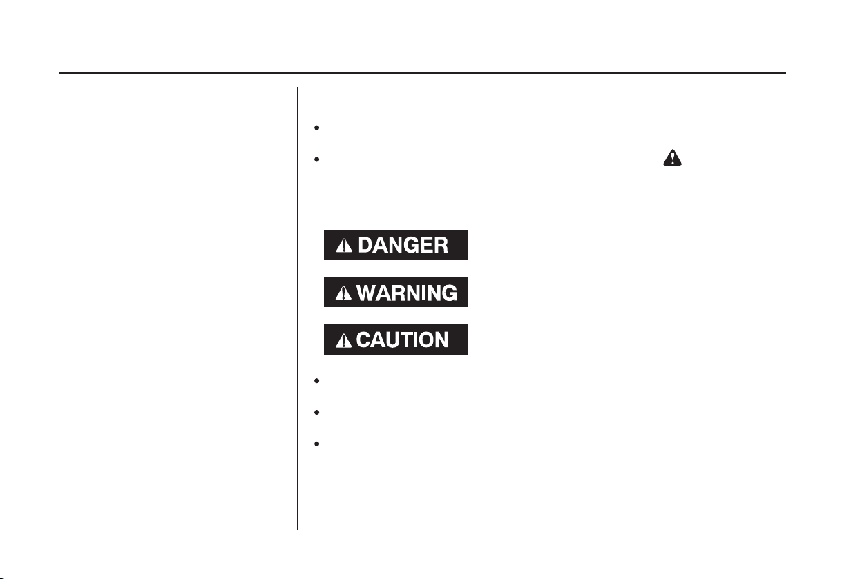
three signal words, DANGER, WARNING, or CAUTION.
These signal words mean:
Safety Headings
Safety Section
Instructions
This entire book is filled with important saf ety information please read it
carefully.
−
on the outboard motor.
−
preceded by a safety alert symbol and one of
You WILL be KILLED or SERIOUSLY
HURT if you don’t follow instructions.
You CAN be KILLED or SERIOUSLY
HURT if you don’t follow instructions.
You CAN be HURT if you don’t follow
instructions.
−
such as
−
such as
−
how to use this outboard motor correctly and safely.
IMPORTANT SAFETY INFORMATION.
OUTBOARD MOTOR SAFETY.
−
2

CONTENTS
CONTROL AND FEATURE
..............................................................CONTROLS . 19
H Type (tiller handle)
..........................................................Throttle Grip . 20
.....................................................Gearshift Lever . 20
................................................Recoil Starter Grip . 21
Electric Starter Button
.........................................Steering Friction Lever . 21
................................................Tilt Lever (G type) . 22
R Type (remote control)
......................................................Ignition Switch . 23
.......................................................Fast Idle Lever . 24
...................................OUTBOARD MOTOR SAFETY . 7
................IMPORTANT SAFETY INFORMATION . 7
................................SAFETY LABEL LOCATIONS . 9
..................................CONTROLS AND FEATURES . 10
................................IDENTIFICATION CODES . 10
....COMPONENT AND CONTROL LOCATIONS . 14
....................Engine Stop Switch and Switch Clip . 19
....................Choke Knob (H type manual choke) . 19
.....................................Throttle Friction Adjuster . 20
.............(models equipped with electric starter) . 21
....................................Power Tilt Switch (T type) . 22
.............Switch Clip and Emergency Stop Switch . 23
..........................Gearshift/Throttle Control Lever . 25
....................................Power Tilt Switch (T type) . 26
...............................Manual Relief Valve (T type) . 26
...........................Tilt Lock Lever (G and T types) . 27
Common Controls
..............................................Engine Cover Latch . 27
.............................Transom Angle Adjusting Rod . 27
..................................Tilt Lever (manual tilt type) . 28
.......................................................INSTRUMENTS . 29
............................................................Fuel Gauge . 29
.........................Tachometer (optional equipment) . 29
...........................................................INDICATORS . 30
...............Oil Pressure Indicator (R type) (H type) . 30
..................................Overheat Indicator (R type) . 30
.....................................Cooling System Indicator . 31
................................................OTHER FEATURES . 31
.....................................................Overrev Limiter . 31
Automatic Choke
.............(models equipped with electric starter) . 31
...................................................................Anodes . 31
................................................Portable Fuel Tank . 32
.............................................Fuel Cap Vent Knob . 32
.................................................Fuel Priming Bulb . 32
3

CONTENTS
..........................................................INSTALLATION . 33
.....................................POWER REQUIREMENTS . 33
..................................INSTALLATION POSITION . 33
.......................................................ATTACHMENT . 34
...................................BATTERY CONNECTIONS . 35
................................................BEFORE OPERATION . 38
IS YOUR OUTBOARD MOTOR
?
................................................READY TO GO . 38
................................................................OPERATION . 40
.......................................BREAK-IN PROCEDURE . 40
...................BOAT TRANSOM REQUIREMENTS . 33
.....................TRANSOM ANGLE ADJUSTMENT . 35
?
.....ARE YOU READY TO GET UNDER WAY . 38
....................SAFE OPERATING PRECAUTIONS . 40
.....................TRANSOM ANGLE ADJUSTMENT . 41
.......................................PORTABLE FUEL TANK . 43
................................FUEL HOSE CONNECTIONS . 43
.......................................................FUEL PRIMING . 44
......................................STARTING THE ENGINE . 44
............................................H Type (tiller handle) . 44
........................................R Type (remote control) . 47
.....................................EMERGENCY STARTING . 49
.......................................STOPPING THE ENGINE . 52
................................Emergency Engine Stopping . 52
.......................................Normal Engine Stopping . 52
GEARSHIFT AND
..............................THROTTLE OPERATION . 54
............................................H Type (tiller handle) . 54
........................................R Type (remote control) . 55
...............................................................STEERING . 56
............................................H Type (tiller handle) . 56
........................................R Type (remote control) . 56
................................................................CRUISING . 57
........................SHALLOW WATER OPERATION . 59
...............MOORING, BEACHING, LAUNCHING . 62
4

CONTENTS
..............SERVICING YOUR OUTBOARD MOTOR . 64
.....................................MAINTENANCE SAFETY . 65
TOOL KIT AND EMERGENCY STARTER
.....................................................................ROPE . 66
...............................MAINTENANCE SCHEDULE . 67
......................MANUAL RELIEF VALVE (T type) . 69
ENGINE COVER REMOVAL AND
..................................................INSTALLATION . 69
............................................Engine Oil Level Check . 70
....................................................Engine Oil Change . 71
.......................................................Oil Filter Change . 72
..................................Engine Oil Recommendations . 73
................................................Gear Oil Level Check . 73
........................................................Gear Oil Change . 74
.....................................................Lubrication Points . 76
....................................................Spark Plug Service . 77
.............................................................REFUELING . 79
...............................FUEL RECOMMENDATIONS . 80
....................Portable Fuel Tank and Filter Cleaning . 82
.................................Recoil Starter Rope Inspection . 83
..................................................Anode Replacement . 83
..............................................Propeller Replacement . 84
...........THE IMPORTANCE OF MAINTENANCE . 64
.........Fuel Pump Filter Inspection and Replacement . 80
....................................................................STORAGE . 85
...................................STORAGE PREPARATION . 85
..........................................Cleaning and Flushing . 85
........................................................................Fuel . 87
.............................................................Engine Oil . 89
...................................STORAGE PRECAUTIONS . 89
...............................REMOVAL FROM STORAGE . 90
........................................................TRANSPORTING . 91
WITH OUTBOARD MOTOR INSTALLED
.............................................................ON BOAT . 91
WITH OUTBOARD MOTOR REMOVED
.......................................................FROM BOAT . 91
TAKING CARE OF UNEXPECTED
..........................................................PROBLEMS . 92
BATTERY WILL NOT CHARGE AND
.ELECTRIC STARTER WILL NOT OPERATE . 97
OIL PRESSURE INDICATOR LIGHT GOES OFF
...................AND ENGINE SPEED IS LIMITED . 98
OVERHEAT AND ENGINE SPEED IS
..............................................................LIMITED . 99
........................................SUBMERGED MOTOR . 101
5

CONTENTS
TECHNICAL AND CONSUMER
.................................................INFORMATION . 103
.............................TECHNICAL INFORMATION . 103
......................................Serial Number locations . 103
Carburetor Modification for High Altitude
.........................................................Operation . 104
................................................Oxygenated Fuels . 105
............................................................Star Label . 108
......................................................Specifications . 110
.............................CONSUMER INFORMATION . 118
.............................................Honda Publications . 118
............................Warranty Service Information . 118
.........................................................................INDEX . 119
.........................WIRING DIAGRAMS . Inside back cover
...............Emission Control System Information . 106
This Owner’s Manual is using the following type names
when it describes the operations special to a type.
Tiller handle type:
Remote control type:
Gas assist type:
Power tilt type:
Check the type of your outboard motor and read this
Owner’s Manual thoroughly before operation.
Texts with no type indication are the information and/or
procedures common to all types.
H type
R type
G type
T type
6

OUTBOARD MOTOR SAFETY
IMPORTANT SAFETY INFORMATION
Honda BF8D/BFP8D/BF9.9D/
BFP9.9D/BF15D/BFP15D/BF20D
and BFP20D outboard motors are
designed for use with boats that have
a suitable manufacturer’s power
recommendation. Other uses can
result in injury to the operator or
damage to the outboard motor and
other property.
Most accidents can be prevented if
you follow all instructions in this
manual and on the outboard motor.
The most common hazards are
discussed below, along with the best
way to protect yourself and others.
Operator Responsibility
It is the operator’s responsibility to
provide the necessary safeguards
to protect people and property.
Know how to stop the engine
quickly in case of emergency.
Understand the use of all controls.
Stop the engine immediately if
anyone falls overboard, and do not
run the engine while the boat is
near anyone in the water.
Always stop the engine if you
must leave the controls for any
reason.
Attach the emergency stop switch
lanyard securely to the operator.
Always wear a PFD (Personal
Flotation Device) while on the
boat.
Familiarize yourself with all laws
and regulations relating to boating
and the use of outboard motors.
Be sure that anyone who operates
the outboard motor receives proper
instruction.
Be sure the outboard motor is
properly mounted on the boat.
Do not remove the engine cover
while the engine is running.
7

OUTBOARD MOTOR SAFETY
Carbon Monoxide HazardRefuel With Care
Gasoline is extremely flammable,
and gasoline vapor can explode.
Refuel outdoors, in a wellventilated area, with the engine
stopped. Never smoke near
gasoline, and keep other flames
and sparks away.
Remove any portable fuel tank
from the boat for refueling. Keep
the portable fuel tank away from
the battery or other potential spark
sources.
Refuel carefully to avoid spilling
fuel. Avoid overfilling the fuel
tank.
After refueling, tighten the filler
cap securely. If any fuel is spilled,
make sure the area is dry before
starting the engine.
Exhaust gas contains poisonous
carbon monoxide. Avoid inhalation
of exhaust gas. Never run the engine
in a closed garage or confined area.
8
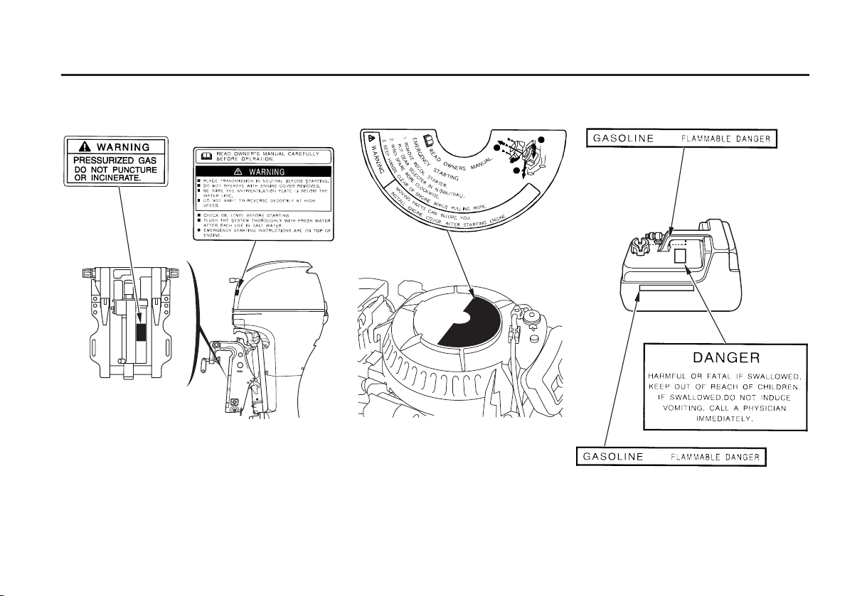
SAFETY LABEL LOCATIONS
OUTBOARD MOTOR SAFETY
The labels shown here contain important safety information. Please read them carefully. These labels are considered
permanent parts of your outboard motor. If a label comes off or becomes hard to read, contact an authorized Honda
Marine servicing dealer for a replacement.
9
CONTROLS AND FEATURES
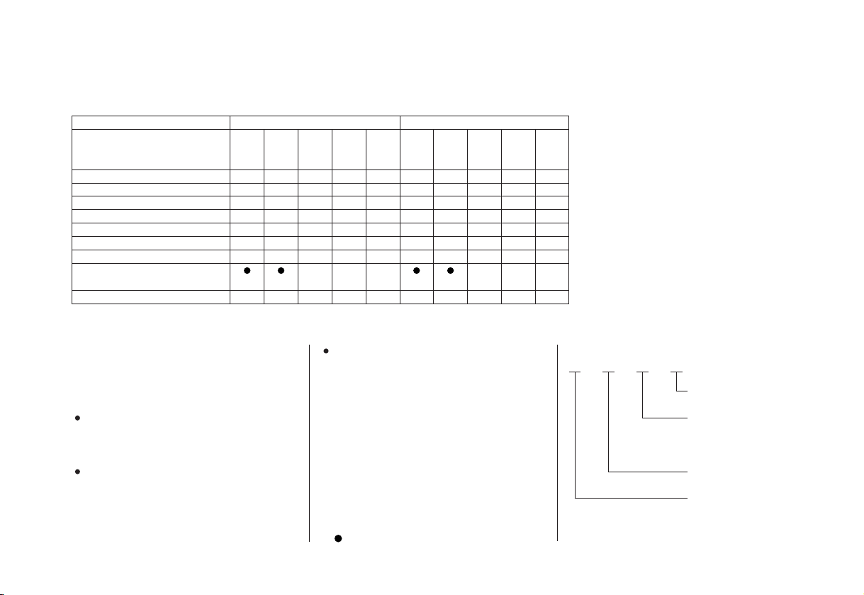
CONTROL AND FEATURE IDENTIFICATION CODES
Model
Type
Shaft Length
Tiller Handle
Remote Control
Electric Starter
Gas assist Tilt
Power Tilt
Power Thrust Propeller
Battery Charging DC
Receptacle
Tachometer
SHA
S
H
LHA
L
H
BF8D
SHSA
S
H
S
LHSA
L
H
S
BFP8D
LRA
LHA
XHA
XHSA
LHTA
L
L
X
X
H
R
S
* *
H
P
P
L
H
H
S
S
T
P
P
XRTA
X
R
S
T
P
Refer to this chart for an explanation of the Type Codes used in this manual to identify control and feature applications.
BF8D/BFP8D are provided with the
following types according to the shaft
length, control system, tilt system, and start
system.
Tilt system
Gas assist Tilt (with gas damper
G:
assist function)
Power Tilt (with hydraulic assist
T:
(Example)
LHSA
function)
Shaft Length
S: Short Shaft
L: Long Shaft
X: Extra Long Shaft
Control System
H: Tiller Handle Control
R: Remote Control
Optional Equipment
:
*
Standard Equipment
:
Destination
A=United States
S=Electric Starter
G=Gas assist Tilt
T=Power Tilt
None=Manual Tilt
R=Remote Control
H=Tiller Handle
S=Short Shaft
L=Long Shaft
X=Extra Long Shaft
10
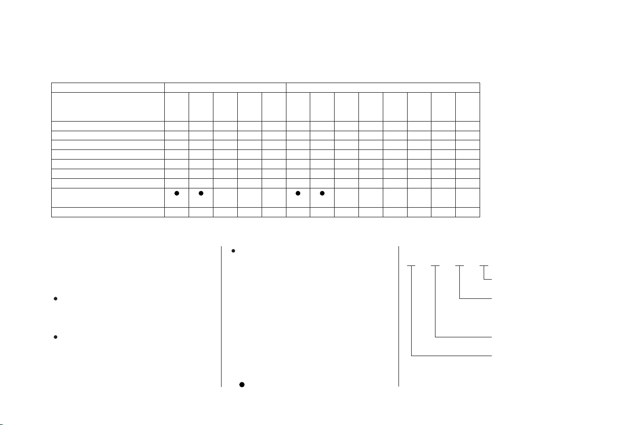
Model
BFP9.9DBF9.9D
Type
Shaft Length
Tiller Handle
Remote Control
Electric Starter
Gas assist Tilt
Power Tilt
Power Thrust Propeller
Battery Charging DC
Receptacle
Tachometer
SHA
S
H
LHA
L
H
SHSA
S
H
S
LHSA
L
H
S
LRA
L
R
S
LHA
L
H
P
XHA
X
H
P
XHSA
X
H
S
P
LRA
L
R
S
P
LHTA
L
H
S
T
P
LRTA
L
R
S
T
P
XRTA
X
R
S
T
P
*** *
XHTA
X
H
S
T
P
Refer to this chart for an explanation of the Type Codes used in this manual to identify control and feature applications.
BF9.9D/BFP9.9D are provided with the
following types according to the shaft
length, control system, tilt system, and start
system.
Tilt system
Gas assist Tilt (with gas damper
G:
assist function)
Power Tilt (with hydraulic assist
T:
(Example)
LHSA
function)
Shaft Length
S: Short Shaft
L: Long Shaft
X: Extra Long Shaft
Control System
H: Tiller Handle Control
R: Remote Control
Optional Equipment
:
*
Standard Equipment
:
Destination
A=United States
S=Electric Starter
G=Gas assist Tilt
T=Power Tilt
None=Manual Tilt
R=Remote Control
H=Tiller Handle
S=Short Shaft
L=Long Shaft
X=Extra Long Shaft
11
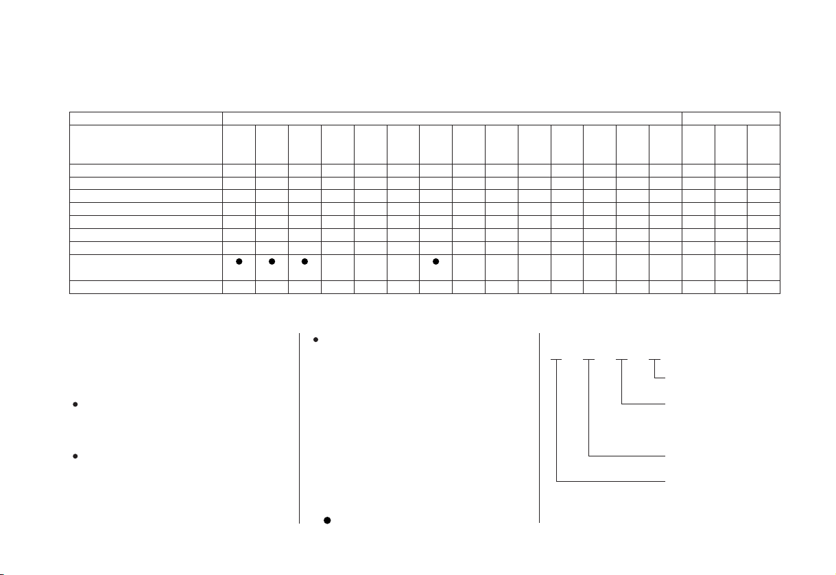
Model BFP15D
LHSA
Type LGA
SHA
LHA
XHA
SHSA
LRA
BF15D
SHGA
LHGA
XHGA
LHTA
SRTA
SHTA
LRTA
XHTA
LRTA
XRTA
Shaft Length
Tiller Handle
Remote Control
Electric Starter
Gas assist Tilt
Power Tilt
Power Thrust Propeller
Battery Charging DC
Receptacle
Tachometer
S
L
H
X
H
H
L
S
H
S
L
H
R
S
S
* ****
S
L
L
H
H
S
G
G
X
H
H
S
S
G
G
S
L
H
R
S
S
T
T
Refer to this chart for an explanation of the Type Codes used in this manual to identify control and feature applications.
BF20D/BFP20D are provided with the
following types according to the shaft
length, control system, tilt system, and start
system.
Tilt system
Gas assist Tilt (with gas damper
G:
assist function)
Power Tilt (with hydraulic assist
T:
(Example)
LHSA
function)
Shaft Length
S: Short Shaft
L: Long Shaft
X: Extra Long Shaft
Control System
H: Tiller Handle Control
R: Remote Control
Optional Equipment
:
*
Standard Equipment
:
12
L
L
H
R
S
S
T
T
L
X
H
S
T
P
X
R
R
S
S
T
T
P
P
Destination
A=United States
S=Electric Starter
G=Gas assist Tilt
T=Power Tilt
None=Manual Tilt
R=Remote Control
H=Tiller Handle
S=Short Shaft
L=Long Shaft
X=Extra Long Shaft
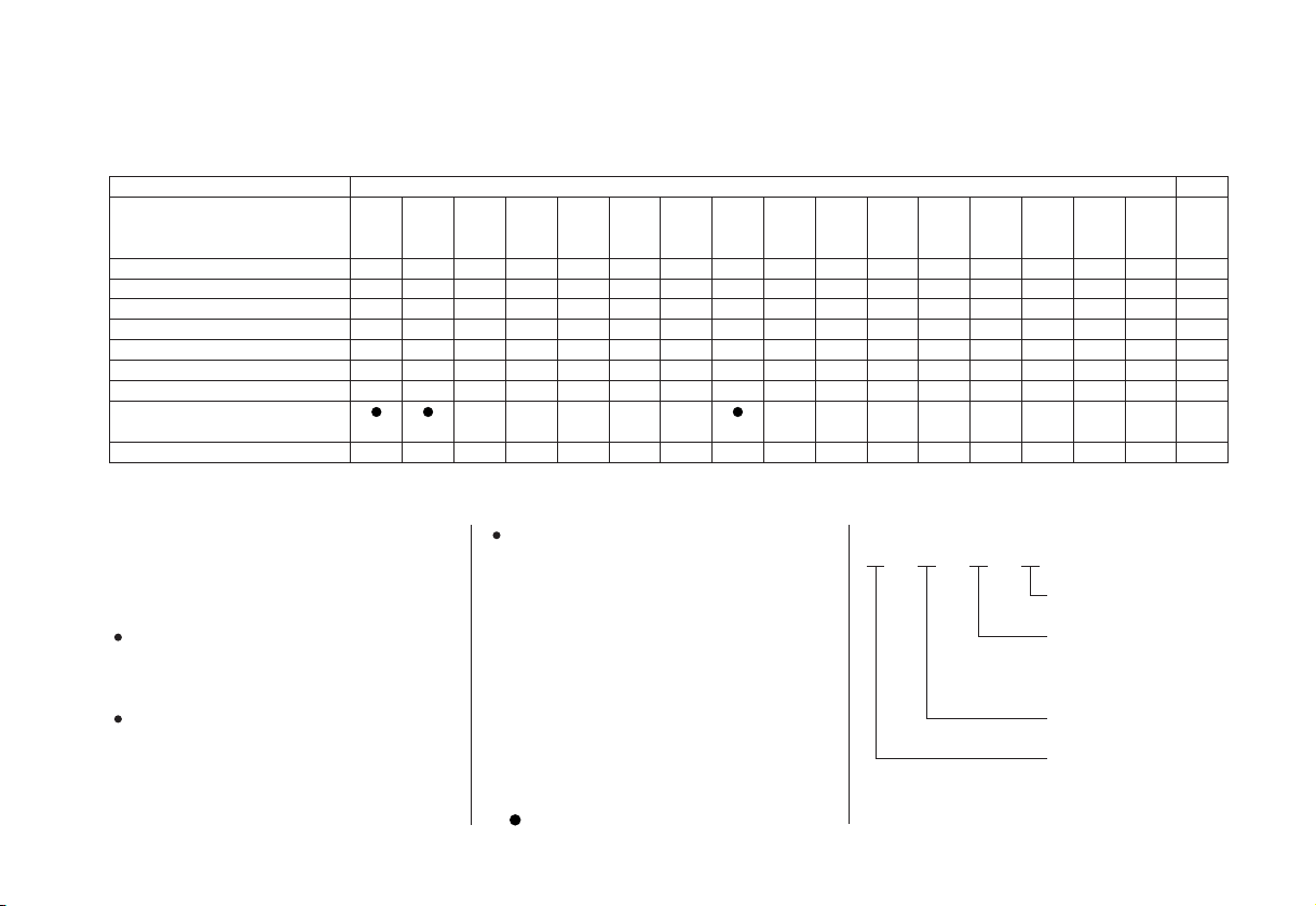
Model
BF20D
BFP20D
Type SHSA
Shaft Length
Tiller Handle
Remote Control
Electric Starter
Gas assist Tilt
Power Tilt
Power Thrust Propeller
Battery Charging DC
Receptacle
Tachometer
SHA
S
H
LHA
L
H
LHSA
XHSA
SRA
LRA
LGA
S
L
X
S
L
H
H
H
S
S
R
S
S
** ***
L
H
R
S
G
SHGA
S
H
S
G
LHGA
L
H
S
G
XHGA
X
H
S
G
SHTA
S
H
S
T
LHTA
L
H
S
T
Refer to this chart for an explanation of the Type Codes used in this manual to identify control and feature applications.
BF20D/BFP20D are provided with the
following types according to the shaft
length, control system, tilt system, and start
system.
Tilt system
Gas assist Tilt (with gas damper
G:
assist function)
Power Tilt (with hydraulic assist
T:
(Example)
LHSA
function)
Shaft Length
S: Short Shaft
L: Long Shaft
X: Extra Long Shaft
Control System
H: Tiller Handle Control
R: Remote Control
Optional Equipment
:
*
Standard Equipment
:
XHTA
SRTA
LRTA
X
S
H
R
S
S
T
T
Destination
A=United States
S=Electric Starter
G=Gas assist Tilt
T=Power Tilt
None=Manual Tilt
R=Remote Control
H=Tiller Handle
S=Short Shaft
L=Long Shaft
X=Extra Long Shaft
LRTA
L
L
R
R
S
S
T
T
P
13
CONTROLS AND FEATURES
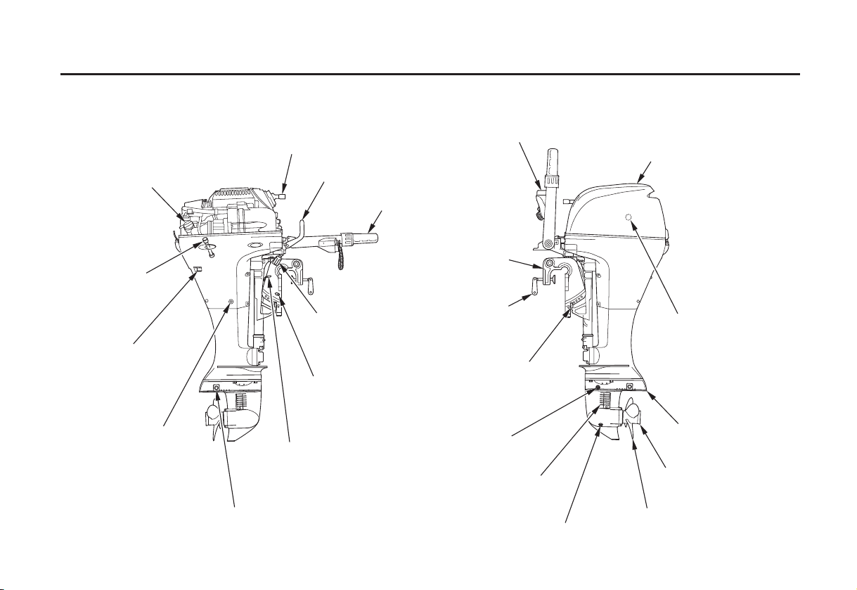
COMPONENT AND CONTROL LOCATIONS
H Type (tiller handle)
RECOIL STARTER GRIP
OIL FILLER CAP
OIL LEVEL
DIPSTICK
COOLING SYSTEM
INDICATOR
ENGINE OIL
DRAIN SCREW
ANODES
SHIFT LEVER
TILLER HANDLE
TILT LEVER
(manual tilt type only)
MANUAL
RELIEF VALUE
(T type only)
TILT LEVER
(G type only)
ELECTRIC STARTER BUTTON
(electric starter type only)
STERN BRACKET
CLAMP SCREW
TRANSOM ANGLE
ADJUSTING ROD
GEAR OIL
LEVEL PLUG
COOLING WATER
INTAKE PORT
GEAR OIL DRAIN/FILL PLUG
ENGINE COVER
FLUSH PORT HOLE
(inside engine cover)
ANTIVENTILATION
PLATE
EXHAUST PORT
PROPELLER
14
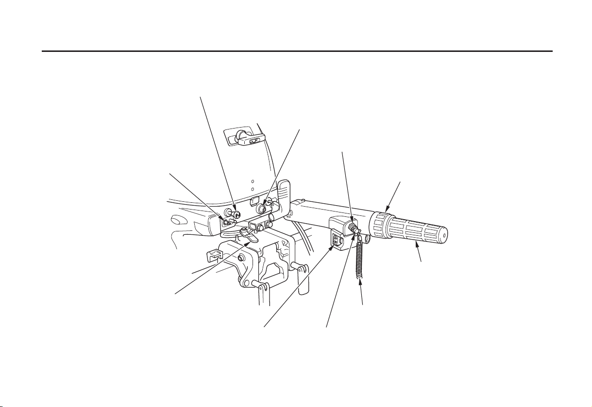
CHOKE KNOB (equipped type only)
CONTROLS AND FEATURES
OIL PRESSURE INDICATOR LIGHT
SWITCH CLIP
FUEL HOSE CONNECTOR
STEERING FRICTION LEVER
POWER TILT SWITCH
(T type only)
THROTTLE FRICTION
ADJUSTER
THROTTLE GRIP
LANYARD
ENGINE STOP SWITCH
15
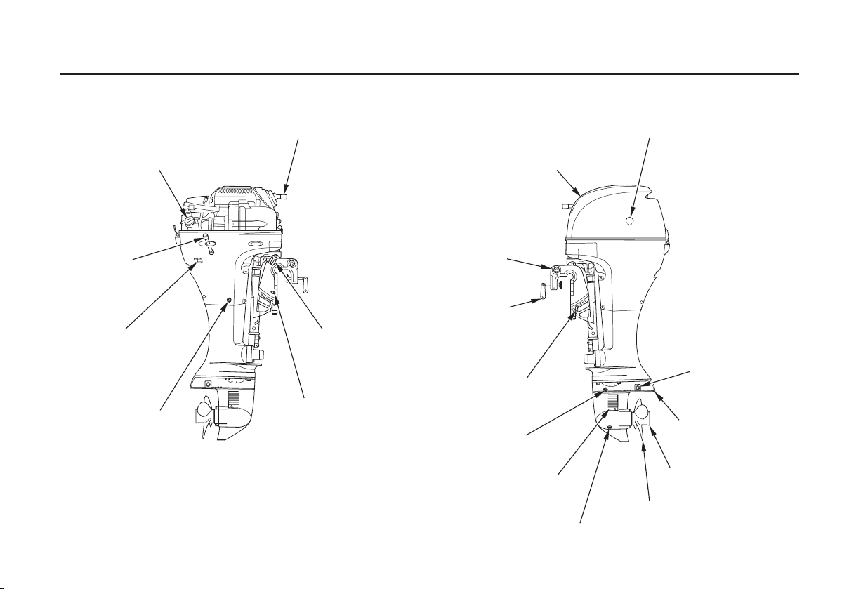
CONTROLS AND FEATURES
R Type (remote control)
OIL FILLER CAP
OIL LEVEL
DIPSTICK
COOLING SYSTEM
INDICATOR
ENGINE OIL
DRAIN SCREW
RECOIL STARTER GRIP
TILT LEVER
(manual tilt type only)
MANUAL
RELIEF VALVE
(T type only)
ENGINE COVER
STERN BRACKET
CLAMP SCREW
TRANSOM ANGLE
ADJUSTING ROD
GEAR OIL
LEVEL PLUG
COOLING WATER
INTAKE PORT
GEAR OIL DRAIN/FILL PLUG
FLUSH PORT HOLE (inside engine cover)
ANODES
ANTIVENTILATION
PLATE
EXHAUST PORT
PROPELLER
16
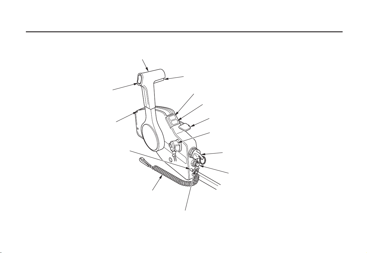
GEARSHIFT/THROTTLE CONTROL LEVER
NEUTRAL RELEASE LEVER
CONTROLS AND FEATURES
POWER TILT SWITCH
(T type only)
SPARE SWITCH CLIP
REMOTE CONTROL
FRICTION ADJUSTER
OIL PRESSURE INDICATOR LIGHT
OVERHEATING INDICATOR LIGHT
FAST IDLE LEVER
BUZZER (inside box)
IGNITION SWITCH
EMERGENCY STOP SWITCH
LANYARD
SWITCH CLIP
17
CONTROLS AND FEATURES
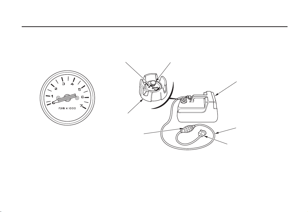
FUEL GAUGE VENT KNOB
TACHOMETER
(optional equipment)
(R type)
PRIMING BULB
FUEL TANK
FUEL CAP
FUEL HOSE
FUEL HOSE CONNECTOR
(FEMALE)
18
CONTROLS AND FEATURES
CONTROLS
H Type (tiller handle)
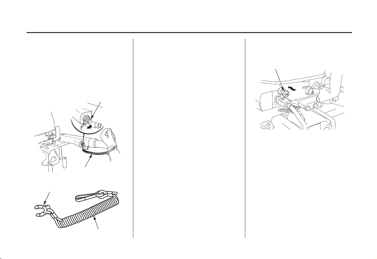
Engine Stop Switch and Switch
Clip
ENGINE STOP
SWITCH
LANYARD
SWITCH CLIP
The engine stop switch has controls
for normal engine stopping and
emergency engine stopping.
The switch clip must be inserted in
the engine stop switch in order for
the engine to start and run. The
lanyard should be attached to the
operator’s PFD (Personal Flotation
Device) or worn around the wrist as
shown.
When used as described, the engine
stop switch and lanyard system stops
the engine if the operator falls away
from the controls.
A spare switch clip is supplied with
the motor.
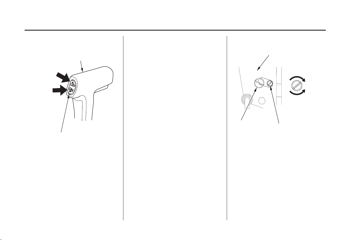
Choke Knob (H type manual choke)
CHOKE KNOB
OOPPEENN
CCLLOOSSEEDD
The choke knob opens and closes the
choke valve in the carburetor.
The CLOSED position enriches the
fuel mixture for starting a cold
engine.
The OPEN position provides the
correct fuel mixture for operation
after starting, and for restarting a
warm engine.
LANYARD
19
CONTROLS AND FEATURES
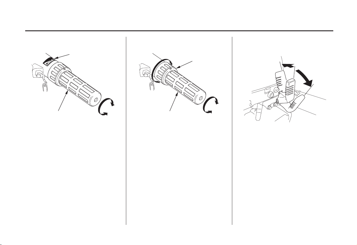
Throttle Grip Gearshif t LeverThrottle Friction Adjuster
THROTTLE INDEX
MARK
THROTTLE GRIP
The throttle grip controls engine
speed.
An index mark on the tiller arm
shows throttle position and is helpf ul
for setting the throttle correctly when
starting (p. ).
45
FIX
THROTTLE FRICTION ADJUSTER
RELEASE
THROTTLE GRIP
The throttle friction adjuster adjusts
resistance to throttle grip rotation.
Turn the adjuster clockwise to
increase friction for holding a throttle
setting while cruising.
Turn the adjuster counterclockwise to
decrease friction for easy throttle grip
rotation.
R (reverse)
N (neutral)
F(forward)
The gearshift lever is used to select F
(forward), N (neutral), or R (reverse)
gears.
The engine can be started with the
gearshift lever in the N (neutral)
position only.
If the gearshift lever is in the F
(forward) or R (reverse) position, the
recoil starter will not operate, and the
electric starter button (applicable
models) will not operate the starter
motor.
20
CONTROLS AND FEATURES
Recoil Starter Grip Electric Starter Button (models
equipped with electric starter)
STARTER GRIP
SWITCH
Pull the starter grip to operate the
recoil starter for starting the engine
manually.
The engine will not start unless the
gearshift lever (p. ) is in the N
20 20
(neutral) position, and the clip is in
the engine stop switch.
CLIP
Press the starter button to operate the
electric starter for starting the engine.
The electric starter button can be
used to start the engine only when the
gearshift lever (p. ) is in the N
(neutral) position, and the clip is in
the engine stop switch.
ELECTRIC STARTER
BUTTON
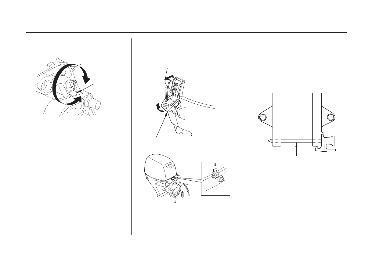
Steering Friction Lever
LLOOCCKK
STEERING FRICTION LEVER
The steering friction lever adjusts
steering resistance.
Less friction allows the outboard
motor to turn more easily. More
friction helps to hold steady course
while cruising or to prevent the
outboard motor from swinging while
trailering the boat.
FFRREEEE
21
CONTROLS AND FEATURES
Power Tilt Switch (T type) Tilt Lever (G type)
Press UP
to tilt the
motor up.
Press DN to tilt
the motor down.
POWER TILT SWITCH
The rocker type power tilt switch has
UP and DN (down) positions for
During shallow water operation,
beaching, launching, or mooring,
proceed at low speed with a small
throttle opening and tilt the motor up
as necessary (p. ).59
(gas assist tilt type)
TTIILLTT
RRUUNN
((LLOOCCKK))
changing the angle of the outboard
motor.
Moving the tilt lever to the TILT
position allows the outboard motor to
Power tilt is a convenience for
tilting the motor, shallow water
operation, and trailer only. It is not
designed to be used as a trim
function to adjust the trim angle
of the boat.
be tilted and moving the tilt lever to
the RUN (LOCK) position locks the
outboard motor in the desired
position. Use the tilt lever to
temporarily tilt the outboard motor
when the boat is operating in shallow
water, or mooring in shallow water.
The tilt lever must be in the RUN
(LOCK) position before operating
the outboard motor or the motor
could tilt up when operating in
reverse.
TILT LEVER
22
CONTROLS AND FEATURES
R Type (remote control)
For panel-mount or top-mount
remote control information, refer to
the instructions provided with the
remote control equipment.
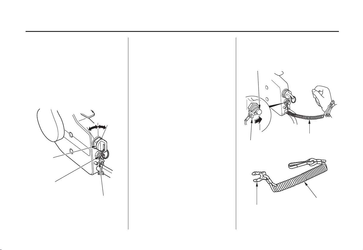
Ignition Switch (side-mount
type)
OONN
OOFFFF
IGNITION
SWITCH
EMERGENCY STOP
SWITCH
SWITCH CLIP
The ignition switch controls the
ignition system and starter motor.
SSTTAARRTT
Turning the ignition switch key to the
START position operates the starter
motor. The key automatically returns
to the ON position when released
from the START position.
The ignition switch can be used to
start the engine only when the
gearshift lever (p. ) is in the N
20
(neutral) position, and the switch clip
is in the emergency stop switch.
Turning the ignition switch to the
OFF position stops the engine.
Switch Clip and Emergency Stop
Switch (side-mount type)
EMERGENCY
STOP SWITCH
LANYARD
SWITCH CLIP
LANYARD
SWITCH CLIP
23
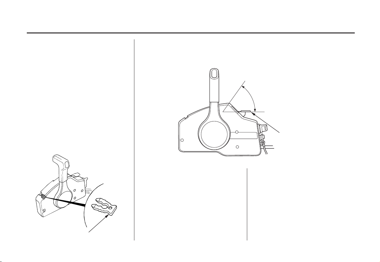
CONTROLS AND FEATURES
The switch clip must be inserted in
the emergency stop switch in order
for the engine to start and run. The
lanyard must be attached to the
operator’s PFD (Personal Flotation
Device) or worn around the wrist as
shown.
When used as described, the
emergency stop switch and lanyard
system stops the engine if the
operator falls away from the controls.
A spare switch clip is stored in a slot
in the control housing.
SPARE SWITCH CLIP
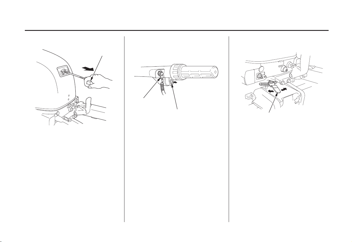
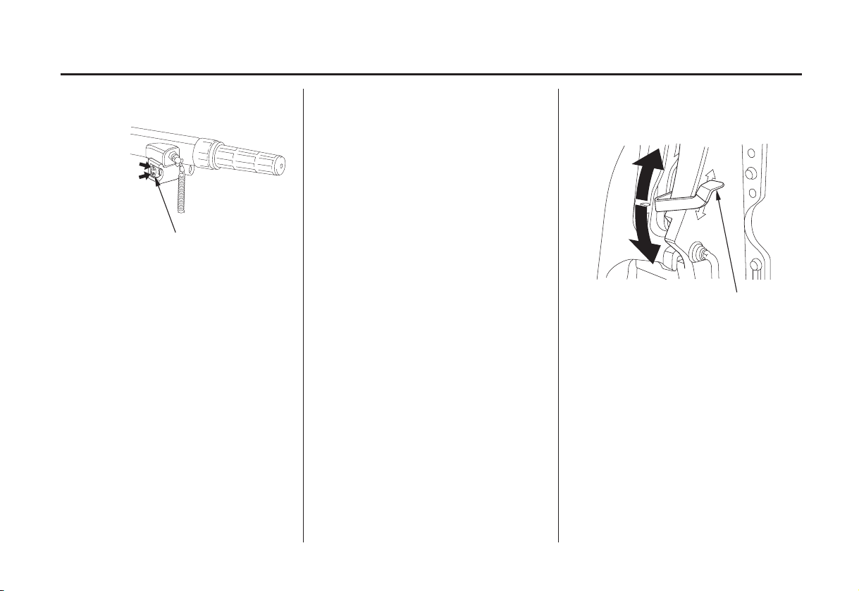
Fast Idle Lever
(side-mount type)
MAXIMUM FAST IDLE
The fast idle lever is used to set idle
speed during warm-up.
The lever will not move unless the
gearshift/throttle control lever is in
the N (neutral) position. Conversely,
the gearshift/throttle control lever
will not move unless the fast idle
lever is in the lowest position.
LOWEST POSITION
FAST IDLE LEVER
Leave the fast idle lever in the lowest
position to provide a rich f uel
mixture for starting a cold engine.
Lift the fast idle lever to warm up a
cold engine after starting and to start
a warm engine.
24
CONTROLS AND FEATURES
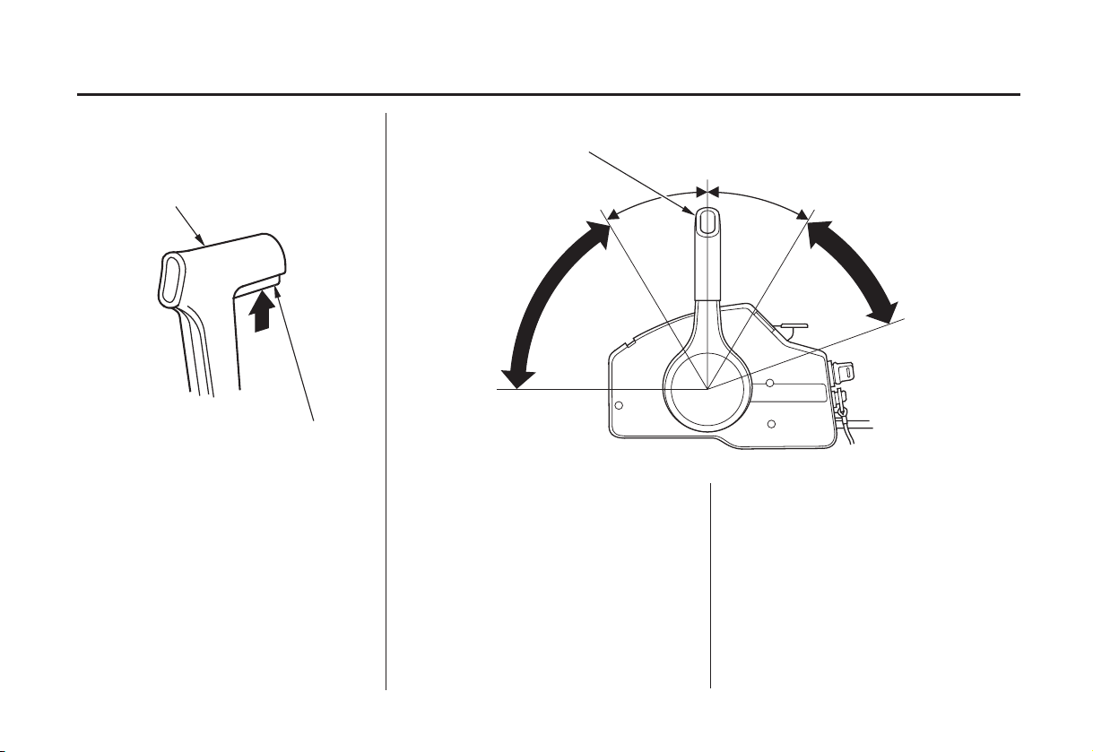
Gearshift/Throttle Control Lever (side-mount type)
GEARSHIFT/THROTTLE
CONTROL LEVER
NEUTRAL RELEASE LEVER
The control lever automatically locks
itself in the N (neutral) position. To
move the lever out of the N (neutral)
position, you must squeeze the
neutral release lever on the underside
of the lever handle.
GEARSHIFT/THROTTLE
CONTROL LEVER
N (neutral)
EENNGGIINNEE
SSPPEEEEDD
HIGH
The gearshift/throttle control lever
controls engine speed and selects F
(forward), N (neutral), or R (reverse)
gears.
Moving the control lever 30° from N
(neutral) selects the gear, and further
movement increases engine speed.
R (reverse)F(forward)
EENNGGIINNEE
SSPPEEEEDD
HIGH
A friction adjuster near the base of
the control lever adjusts the operating
resistance of the control lever (p. ).
55
Less friction allows easier control
lever movement. More friction helps
to hold a steady throttle setting while
cruising.
25
CONTROLS AND FEATURES
Power Tilt Switch (T type) Manual Relief Valve (T type)
(side-mount type)
CONTROL LEVER
Press UP to tilt
the motor up.
Power tilt is a convenience for
tilting the motor, shallow water
operation, and trailer only. It is not
designed to be used as a trim
function to adjust the trim angle of
the boat.
RIGHT STERN BRACKET
MANUAL
(Valve closed
to fix)
During shallow water operation,
beaching, launching, or mooring,
Press DN to tilt
the motor down.
POWER TILT SWITCH
The rocker type power tilt switch is
located on the control lever and has
UP and DN (down) positions for
changing the angle of the outboard
motor.
proceed at low speed with a small
throttle opening and tilt the motor up
as necessary (p. ).59
POWER
(Valve open
to release)
※
※
MANUAL RELIEF VALVE
Do not turn this screw. If this
:
screw is turned hydraulic oil
will bleed out of the power tilt
system. Should this happen it
will be necessary to consult your
authorized Honda Marine dealer
and have the system refilled.
The outboard motor can be tilted
manually after opening the manual
relief valve. This allows the outboard
motor to be tilted when no battery is
connected.
26
CONTROLS AND FEATURES
Tilt Lock Lever
(G and T types)
FFRREEEE
TTIILLTT LLOOCCKK
LLEEVVEERR
LLOOCCKK
The tilt lock lever is used to support
the outboard motor in the fully-raised
position.
When the boat is to be moored for a
long time, tilt the outboard motor as
far as it will go. Then move the tilt
lock lever to the LOCK position, and
gently lower the outboard motor until
the lever contacts the stern bracket.
Common Controls
Engine Cover Latch
EENNGGIINNEE CCOOVVEERR LLAATTCCHH
The engine cover latch fastens the
engine cover to the outboard motor.
Transom Angle Adjusting Rod
The transom angle adjusting rod
limits the tilt angle of the outboard
motor when fully lowered.
(manual tilt SH type/LH type)
ADJUSTING ROD
27
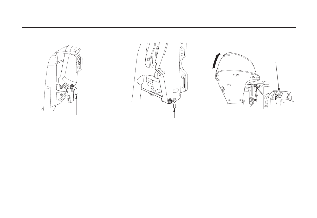
CONTROLS AND FEATURES
ADJUSTING ROD
(G and T type)(manual tilt XH type/R type)
ADJUSTING ROD
(storage location)
There are four transom angle
adjustment positions. There are
controlled by the adjusting rod and
the forth is controlled by the stern
bracket. In order to use the forth
position, remove the adjusting rod
and store it in the storage location,
then lower the motor down to the
stern bracket stop position.
Tilt Lever (manual tilt type)
TILT LEVER
TTIILLTT
RRUUNN
((LLOOCCKK))
The tilt lever enables the outboard
motor to be raised for shallow water
operation, beaching, launching, or
mooring.
To tilt, move the lever to the TILT
position, then raise the outboard
motor until the tilt mechanism
engages at 30°, 45°, 71° or 72°
(p. ).
59
28
 Loading...