

Page 1
Starting from Serial No.:
UTENSIL WASHING MACHINES
INSTALLATION AND
OPERATION INSTRUCTIONS
(original instructions)
REV. 08.10.20108664 0001
UP(T)/UX(T) SERIES
Page 2

2 08.10.2010 BA-21870-001-GB
GB
IMPORTANT NOTES
USE IN ACCORDANCE WITH REGULATIONS:
The machine is technical work equipment for express use in the work place.
The machine is exclusively to be used to wash ware such as pots and pans, baking sheets, cutlery,
trays etc.
Do not use for electrically heated cooking and heat conservation appliances.
Do not put heavy objects on the top of the machine.
SAFETY:
Never hose down the machine.
Do not stand on the open front door of the machine.
The “Attention” symbol is shown beside instructions that are essential for the safe
operation of the machine.
Please read these passages thoroughly.
LIABILITY:
Installations and repairs which are carried out by non-authorized technicians or the use of other than
original spare parts, and any technical alterations to the machine, may affect the warranty set
out in the standard conditions of sale.
MACHINE NOISE LEVEL:
The machine noise level is < 68 dB (A).
CONNECTING TENSIONS:
The machine described in this operation manual has following connecting tensions:
400 V/50 Hz/3 Ph/N/PE.
Page 3

BA-21870-001-GB 08.10.2010 3
GB
CONTENTS Page
1. INSTALLATION ...........................................................5
1.1. Location .............................................................................................5
1.2. Electrical Connection ...........................................................................5
1.3. Water Connection ................................................................................6
1.4. Steam Connection (Steam-Heated Machines Only) ..................................6
1.5. Adjustment of Shut-off Valve for Steam Supply .......................................7
1.6. Drain Connection .................................................................................7
2. DISPENSER CONNECTION ..........................................8
3. CONTROLS ..............................................................10
4. START UP ................................................................11
4.1. Detergent .........................................................................................11
4.2. Rinse Aid ..........................................................................................11
4.3. Chemical Deficiency Sensor ...............................................................11
4.4. Priming the Suction Hoses .................................................................12
4.5. Softener (Optional) .............................................................................13
5. OPERATION .............................................................14
5.1. Preparation .......................................................................................14
5.2. Run ..................................................................................................15
5.3. Select Program .................................................................................16
6. SWITCH-OFF AND CLEANING THE MACHINE..............17
6.1. Switch-off..........................................................................................17
6.2. Cleaning (Daily) ..................................................................................17
6.3. Cleaning (Weekly) ..............................................................................17
6.4. Hygiene Cycle ...................................................................................18
7. TEMPERATURE PREVIEW ..........................................19
8. FAULTS/INDICATIONS ...............................................20
9. SETTINGS AND COUNTER VALUES ............................21
9.1. Adjustment of Detergent Dosage Quantity ...........................................21
9.2. Adjustment of Rinse Aid Dosage Quantity ............................................21
9.3. Adjustment of Water Hardness ............................................................22
9.4. Cycle Counter ...................................................................................22
9.5. Water Consumption Counter ...............................................................22
9.6. Activation/Deactivation of Acoustic Signals ..........................................23
9.7. Activation/Deactivation of Chemical Sensor .........................................23
9.8. Control of the Detergent Dosage Pump ...............................................23
9.9. Control of the Rinse Aid Dosage Pump Display CH2 .............................24
9.10. Termination of Setting Mode/Counter Display ......................................24
Page 4

4 08.10.2010 BA-21870-001-GB
GB
CONTENTS Page
10. FROST PREVENTION ................................................25
11. MAINTENANCE ........................................................26
12. TROUBLESHOOTING GUIDE ......................................27
12.1. Poor Wash Result ..............................................................................27
12.2. Other Malfunctions.............................................................................28
Page 5
BA-21870-001-GB 08.10.2010 5
GB
1. INSTALLATION
1.1. LOCATION
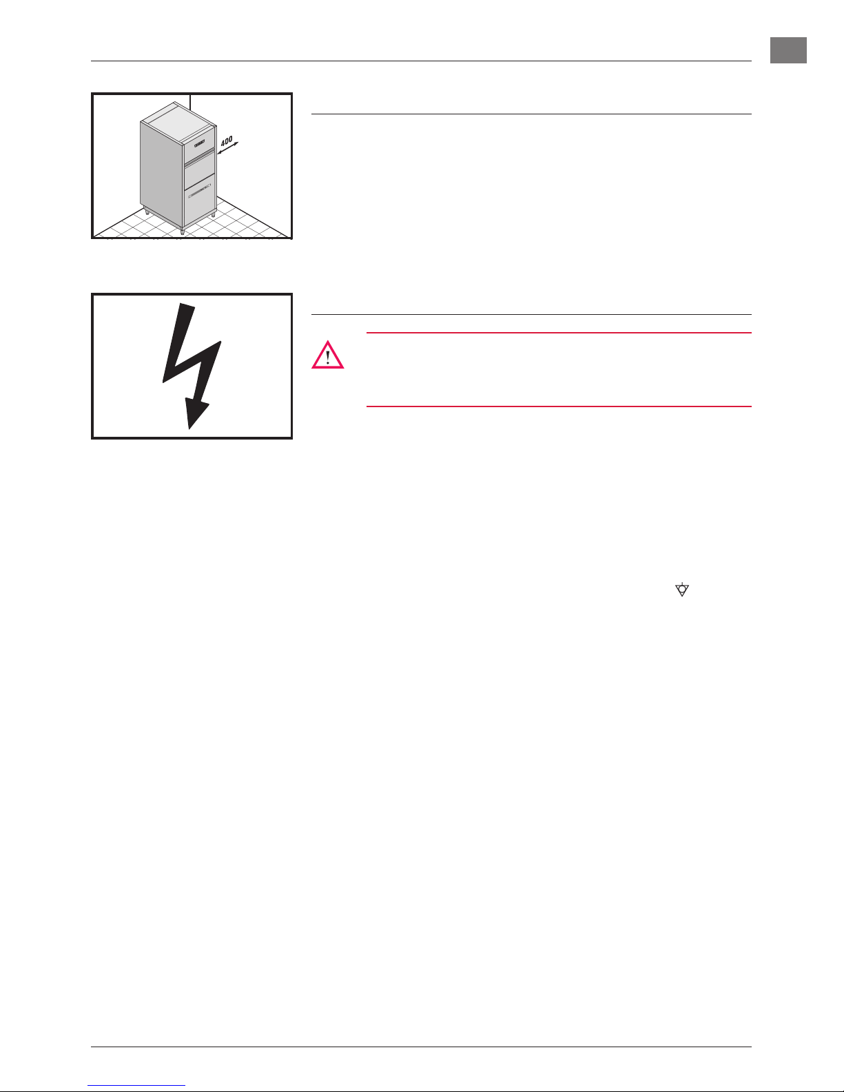
! Wall clearance is not required at the rear.
! The lateral distance between machine and wall should be at least
400 mm on one side.
! To avoid damage of the feet, do not slide the machine on floor after
the skid is removed.
! Level machine by turning the feet.
! Distribute machine weight equally onto all feet.
1.2. ELECTRICAL CONNECTION
Must be carried out by an authorized technician according to
the local and national codes.
For Australia: in accordance with AS/NZS3500.1
! The electrical supply shall comply with the name-plate data.
! Modification to a different electrical supply is possible within the
range of variations designated in the circuit diagram.
! Line fuses and cable cross section shall comply with the require-
ments.
! A cut-off device shall be provided to connect the supply cord (isolat-
ing switch or accessible plug device).
NOTE: According to EN 60 335 the appliance must be connected to
an equipotential conductor. The connecting screw (
) is locat-
ed at the rear of the floor pan beside the cable inlet.
Page 6
6 08.10.2010 BA-21870-001-GB
GB
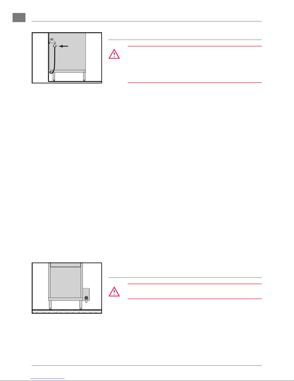
1.3. WATER CONNECTION
Must be carried out by an authorized technician according to
the national and local codes.
The machine must be operated with potable water. For water
with an extremely high mineral content, an external demineralisation is strongly recommended.
! Water temperature:
• If possible, connect to warm water (max. 60 °C).
• Machines with drainwater/exhaust heat recovery:
If possible, connect to cold water (approx. 10 °C).
! Water hardness:
• Machines without softener: max. 3.75° Clark = 0.5 mmol/l.
• Machines with softener: max. 37.5° Clark = 5.3 mmol/l.
! Special feature of PREMAX model UPT:
• Additional separate warm water connection (marked red) for
quicker filling of wash tank.
• If the separate filling of the wash tank with warm water cannot
be realized on site, a HOBART trained service technician must
switch to booster filling via parameter adjustment (S20).
! Line flow pressure:
• Machines without softener: 0.5 - 10 bar
• Machines with softener: 0.8 - 10 bar
• If the line flow pressure is above 10 bar, provide pressure
reducer at source.
! Connect the union nut “A” (3/4”) of the water supply hose to the
site shut off valve.
! Do not kink or cut the supply hose.
! If an extended supply hose is required, use one of the same specifi-
cations as the original.
1.4. STEAM CONNECTION
(STEAM-HEATED MACHINES ONLY)
Must be carried out by an authorized technician according to
the local and national codes.
! Connection to steam supply (DN 20),
0.5 - 3.5 bar (max. 150 °C). See data plate!
! Dimension of steam and condensate piping has to be according to
the requirements.
! The machine is equipped with all necessary fittings.
! Make sure that permissible pressures and temperatures will not be
exceeded.
!
1. INSTALLATION
Page 7

BA-21870-001-GB 08.10.2010 7
GB
1.5. ADJUSTMENT OF SHUT-OFF VALVE FOR
STEAM SUPPLY
! The built-in shut-off valve is equipped with an adjustment device (A)
to limit the steam flow rate. A special tool is necessary for
adjusting the valve-seat.
Attention:
The correct adjustment is very important particularly for higher
pressure, and therefore must be done by a HOBART-trained
service technician at first installation or after any changes are
done at the customer site.
! The adjustment is correct if the heating-up time of the boiler is
as long as the shortest wash cycle, while the valve is opened to
maximum.
! If adjusted too far open pressure shocks may occur when the
solenoid valve closes. This could cause damage at the installation. If adjusted too far close the required heating-power cannot be
achieved.
1.6. DRAIN CONNECTION
! Connection between machine and site drain must not exceed max.
height of 0.80 m.
! Do not place the drain hose loosely on the floor (the hose could be
rubbed through). Fix it at site!
! Do not kink the drain hose.
"
30°-45°
0,80m
1. INSTALLATION
Page 8
8 08.10.2010 BA-21870-001-GB
GB
Generally, all models leaving the factory are equipped with integrated
dispensers.
When retrofitting with other dispensers, please follow the instructions
below.
Attention:
All below-mentioned steps must be carried out by service technicians qualified by Hobart.
Before removing the housing, make sure the machine is voltage-free. Make sure to observe all precautionary measures
required when working near live components.
! Tank must be drained.
! Switch off main switch or unplug.
! Remove front panel.
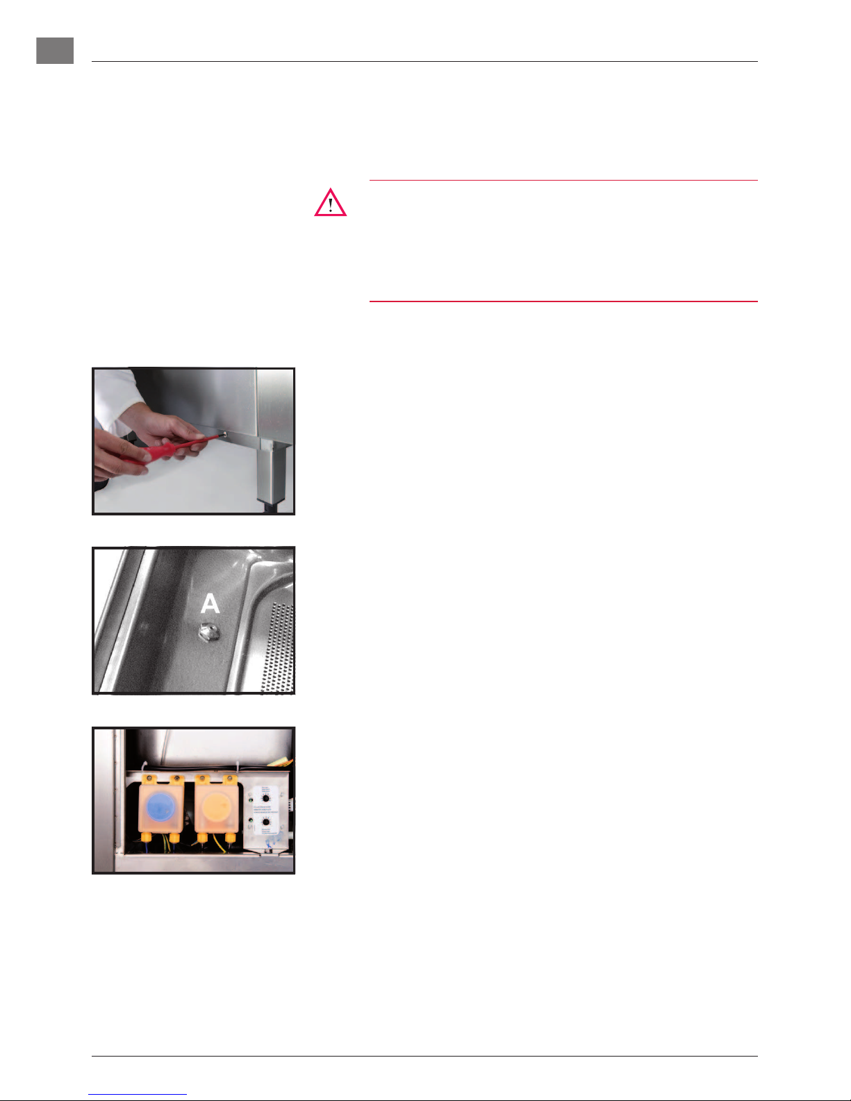
To connect a liquid detergent dispenser:
! For rinse aid dosage, a dosage nipple is available on the top of the
booster.
! Connect a hose (PVC / Ø 6 mm outside × Ø 4 mm inside) between
outlet of the detergent pump and the detergent inlet (A) of the wash
tank. Tighten with hose clamp.
! Install detergent pump or mount externally.
2. DISPENSER CONNECTION
Page 9
BA-21870-001-GB 08.10.2010 9
GB
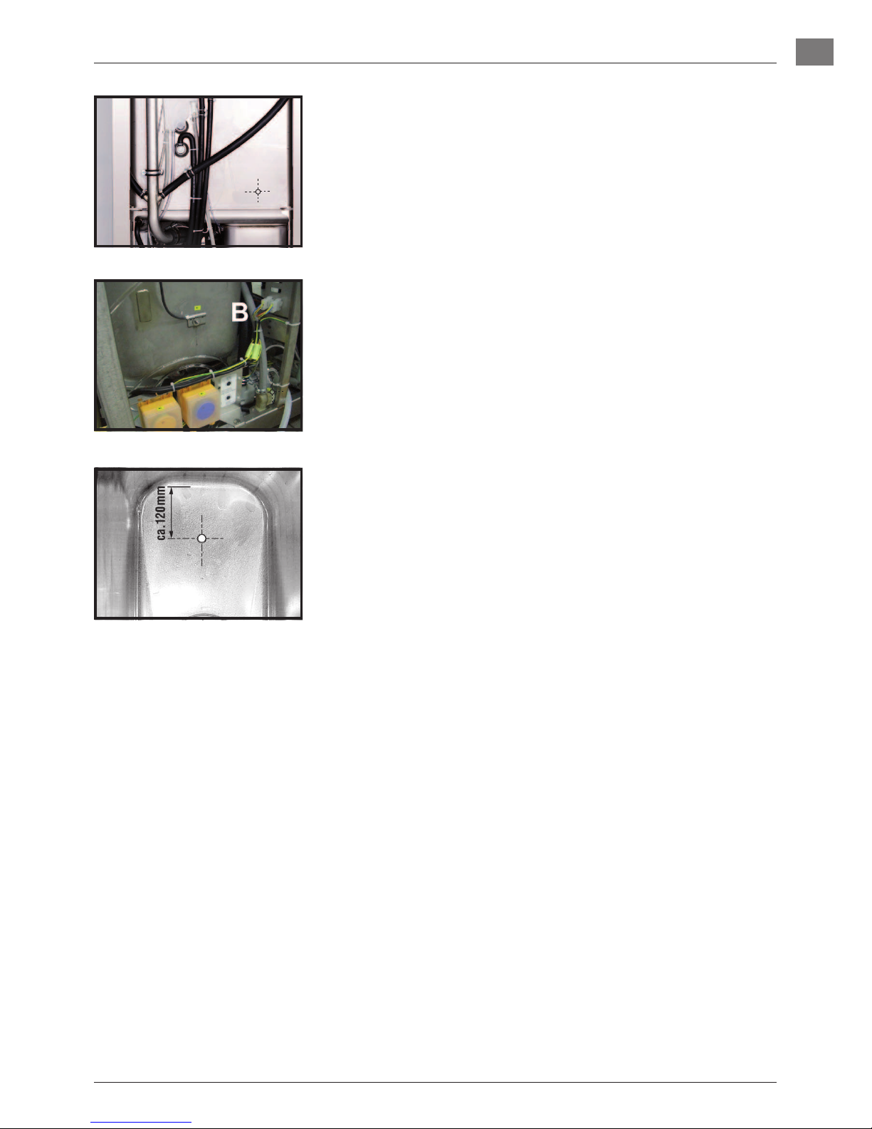
To connect a powder or solid detergent dispenser:
! Remove the rear panel.
! Drill a hole through the inner tank wall appropriate to the required
connection diameter (see fig.).
! Screw the dosing connection tightly to the tank wall.
! Connect the plug (B) of the wire harness with the dosage pump
(max. 100 VA).
Conductivity probe:
! Conductivity probe should be installed at the flat part of tank bot-
tom (see fig.).
! The hole size should be appropriate to the conductivity probe.
! Put panel(s) back into place.
! Switch on main switch at site or put the plug in.
! Dispenser and chemical sensor adjustment (see section 9.).
2. DISPENSER CONNECTION
Page 10

10 08.10.2010 BA-21870-001-GB
GB
3. CONTROLS
➀
ON/OFF-button FUNCTIONS:
– Start machine: Push button.
– Start wash cycle: If the machine is ready for operation, Push button.
– Start automatic drain and self-cleaning cycle:
Push Button and hold for 3 seconds.
Thereafter, machine switches off automatically, but is not voltage free!
DISPLAYS:
The current machine mode is displayed by different colors.
GREEN = Machine is ready for operation
BLUE = Wash cycle is running
RED (permanently) = Failure indication (see section 8.)
GREEN/RED (alternating) = Failure indication (see section 8.)
The status of the program is indicated by the color change of the four button
segments.
Filling increaslingly GREEN
Draining decreaslingly GREEN
Washing from BLUE back to GREEN
Optional:
Exhaust system active circling BLUE segment, background: GREEN
➁
Program button Select between different preset programs: Push button.
Display
➅
shows the selected program number and the corresponding run
time (e.g. P02 240).
➂
Only for PREMAX models UP/UPT:
Direct ON/OFF-switching of the Intensive cycle P03.
➃
Stop button In case of operating error or faults:
Switch off machine immediately (without draining): Push button.
After switch off, the machine is not voltage free!
➄
Display e.g. temperature indication Wash (°C) (see section 7.)
➅
Display e.g. temperature indication Rinse (°C) (see section 7.)
➆
Salt required Insufficient regeneration salt in softener (if built-in)
➇
Detergent/Rinse Aid indicator Detergent or rinse aid deficiency (if chemical sensor is activated)
➈
Hygiene indicator Hygiene cleaning should be carried out (see section 6.4.).
➉
Service indicator Machine operation is faulty (see section 8.).
Page 11

BA-21870-001-GB 08.10.2010 11
GB
Attention:
Head height of dosing pump: max. 1.5 m
Do not swap containers !
Use only commercial detergent and rinse aid. Please pay
attention to the manufacturers safety instructions.
4.1. DETERGENT
Attention:
Do not use any acidic detergent products with the built-in detergent pump! (The ph-value has to be higher than 7.)!
! Place the suction hose into the bottom of the detergent container.
! Fill the suction hose according to section 4.4.
4.2. RINSE AID
! Place the suction hose (marked blue) into the bottom of the deter-
gent container.
! Fill the suction hose according to section 4.4.
4.3. CHEMICAL DEFICIENCY SENSOR
Attention:
All below-mentioned steps must be carried out by service technicians qualified by Hobart.
Before removing the housing, make sure the machine is voltage-free. Make sure to observe all precautionary measures
required when working near live components.
! Carry out hose filling SF1 and SF2 via the customer menu (see
section 4.4.).
! Watch both hoses until the sensor-operated filling is completed.
! The control LEDs must light up. If necessary, readjust the potenti-
ometers (increase setting).
• Factory setting: potentiometer setting for detergent = 3
• Factory setting: potentiometer setting for rinse aid = 5
! Activate the sensor by using CH = “1” in the customer menu (see
section 9.7.).
Klarspüler
Reiniger
4. START UP
Page 12

12 08.10.2010 BA-21870-001-GB
GB
4.4. PRIMING THE SUCTION HOSES
Attention:
The machine has to be switched off.
Is carried out automatically if chemical sensor is activated, but will take
several wash cycles. Therefore, we recommend manual hose priming
as follows:
! Open the door.
! Push Stop button
➃
and Program button ➁ simultaneously until
• the upper display
➅
shows “CH1” and
• the lower display
➄
shows “2.50”.
! Push Program button
➁
repeatedly, until
• the upper display shows “d” and
• the lower display shows “0”.
! Close the door.
• The upper display shows “SF1”,
• The lower display shows “0”.
4.4.1. DETERGENT SUCTION HOSE
! Pushing the ON/OFF button ➀ activates the hose priming for 80
seconds.
! Check the fill level thereafter, and if necessary, repeat.
! Each cycle can be interrupted by pushing the ON/OFF button again.
4.4.2. RINSE AID SUCTION HOSE
! Push the Program button ➁.
• The upper display
➅
shows ”SF2”,
• The lower display
➄
shows “0”.
! Pushing the ON/OFF button
➀
activates the hose priming for 160
seconds.
! Check the fill level thereafter, and if necessary, repeat.
! Each cycle can be interrupted by pushing the ON/OFF button again
4. START UP
Page 13

BA-21870-001-GB 08.10.2010 13
GB
4.4.3. DETERGENT DIRECT INJECTION (UP/UPT ONLY)
! Push the Program button ➁ again.
• The upper display
➅
shows ”SF3”,
• The lower display ➄ shows “0”.
! Pushing the ON/OFF button
➀
activates the hose priming for 20
seconds.
! Check the fill level thereafter, and if necessary, repeat.
! Each cycle can be interrupted by pushing the ON/OFF button again.
4.4.4. TERMINATION OF HOSE PRIMING
! Open door and close it again, or do not press any button for
15 seconds!
4.5. SOFTENER (OPTIONAL)
NOTE: For the first run, the softener has to be filled with regeneration
salt and potable water.
Attention:
Filling the salt reservoir with cleaning agent will damage the
water softener.
! Open the door.
! Unscrew the softener lid and fill with 2 kg of “Granular regeneration
salt” using a funnel (do not use salt tablets).
! Fill up the softener with potable water (only at the first run).
! Clean seal and rim of softener lid carefully, before closing the lid.
! Close lid and tighten.
! In order to prevent corrosion, it is necessary to remove any
salt residues from tank bottom.
! Adjust the water hardness according to section 9.3.!
! When the Salt indicator
➆
illuminates during operation, the soft-
ener has to be refilled with regeneration salt.
! There will be a slight delay before the salt light extinguishes after
refill.
4. START UP
Page 14

14 08.10.2010 BA-21870-001-GB
GB
5.1. PREPARATION
! Check correct position of wash/rinse arms and strainers.
! Open shut-off valve.
! Switch on main switch or put the plug in.
! Check level of detergent and rinse aid containers.
! Close door and push the ON/OFF button
➀
; tank will be filled.
! The ON/OFF button will become gradually green during fill and
heating cycle. This process can take several minutes.
! When the button becomes completely green, machine is ready for
operation.
! Remove coarse food debris.
! Remove foam-producing substances (albumins etc.)
! Pre-treat hard, baked-on food debris (e.g. pre-soak).
! Insert baking sheets into the appropriate rack.
! Avoid overlapping areas.
! Put pots and pans face downwards into the racks.
! Protect light washware by covering with a rack or special weighted
frame.
5. OPERATION
Page 15

BA-21870-001-GB 08.10.2010 15
GB
PREMAX MODEL UPT:
! GN-parts can also be placed in the guide rails of the additional
lateral wash system.
Attention:
When using the lateral wash system, please note that the wash
result is better in the center than on the outer edges.
! Racks can also be hung on the hooks of the additional lateral wash
system.
5.2. RUN
! Load machine and close the door.
! Push the ON/OFF button ➀. During the running wash cycle, the
color of the ON/OFF button changes from blue increasingly back to
green.
Attention:
For PREMAX models UP/UPT, a soaking phase is integrated in
the cycle. During this phase, the machine is silent.
! As soon as the ON/OFF button illuminates completely green, the
wash cycle is finished.
! Open the door and take out rack. Allow washware enough time to
dry.
MACHINES WITH EXHAUST HEAT RECOVERY (OPTIONAL):
! The ON/OFF button ➀ shows a circling blue segment on a green
background as long as steam is exhausted from the machine. For
high capacity requirements, it is not necessary to wait for this process to complete before continuing operation of the machine.
5. OPERATION
Page 16

16 08.10.2010 BA-21870-001-GB
GB
5.3. SELECT PROGRAM
! The machine runs automatically using the Standard cycle program.
If needed, it is possible to select a different program.
! To show the present program, push the Program button before
starting the wash cycle. To change the program, push the Program
button again. The theoretical runtime is then shown in the lower
display.
P01 = Short cycle
P02 = Standard cycle
P03 = Intensive cycle
P04 = Continuous cycle
H = Hygiene cycle (see section 6.4.)
An operating Continuous cycle is shown by the running lights on the
display. To stop the cycle, push the ON/OFF button ➀ (After 20 minutes
the machine will stop automatically.). After a short break, rinse starts
automatically.
The machine continues with the chosen cycle until it is switched off or
another program is chosen.
PREMAX MODELS UP/UPT:
During Intensive cycle P03, a pre-soaking phase occurs using steam and
detergent direct injection. For these models, the Intensive cycle P03 can
also be selected directly by using button ➂. Pushing button ➂ again,
switches the machine back to the Standard cycle.
5. OPERATION
Page 17

BA-21870-001-GB 08.10.2010 17
GB
6.1. SWITCH-OFF
! Close the door.
! Push and hold (approx. 3 seconds) the ON/OFF button ➀ until the
first segment of the blue illuminated button goes out.
NOTE: During the drain cycle, the interior of the machine is cleaned
automatically. A final inspection is recommended to remove
any food debris.
If the interior of the machine is hosed down again manually,
the residual water can be pumped out by pressing and holding
down the ON/OFF button (3 seconds). On a machine which is
already switched off, this starts a shortened drain cycle.
! When the ON/OFF button has gone out completely:
• Switch off main switch or unplug and close the shut-off valve!
NOTE: If no button is pressed for 6 hours, the machine switches off
automatically without draining.
6.2. CLEANING (DAILY)
Attention:
Do not stand on the open front door of the machine.
Attention:
To clean the machine do not use any chloric, acidic or abrasive
products and no metallic brushes.
! Open the door.
! Take out and clean strainers under running water. Please ensure
that food debris does not enter pump intake!
! Clean interior of the machine.
! Put strainers back into place.
! Leave the door open for ventilation.
6.3. CLEANING (WEEKLY)
! Take out wash and rinse arms and flush.
6. SWITCH-OFF AND CLEANING THE MACHINE
Page 18

18 08.10.2010 BA-21870-001-GB
GB
6.4. HYGIENE CYCLE
After reaching a pre-set number of wash cycles, the Hygiene indicator ➈
lights up to indicate that an automatic hygiene cleaning of the machine
interior should be carried out.
! Before end of operation: Put 6 (for UXT/UPT 10) HOBART-Hygiene-
Cleaner Tabs into the machine interior.
! Close the door.
! Push Program button
➁
repeatedly until the upper display shows
“H”.
! Push ON/OFF button
➀
.
As the Hygiene cycle runs (duration dependent on model and water connection up to one hour), the green illuminated segments go out one after
the other. At the end of the cycle, the machine switches off automatically.
! When the ON/OFF button has gone out completely:
• Switch off main switch or unplug and close the shut-off valve!
NOTE: If necessary, hygiene cleaning should be carried out before
reaching the pre-set number of wash cycles. With regular use,
the machine interior will remain free of food debris and deposits.
6. SWITCH-OFF AND CLEANING THE MACHINE
Page 19

BA-21870-001-GB 08.10.2010 19
GB
! Press and hold (3 seconds) the Program button ➁ until the actual
temperatures (°C) are displayed (top = rinse, bottom = wash).
The indicators go out 10 seconds after releasing the Program button.
Permanent temperature display can be activated on request by the
service technician.
7. TEMPERATURE PREVIEW
Page 20

20 08.10.2010 BA-21870-001-GB
GB
A code will be shown in the upper Display ➅ (see table).
Die ON/OFF button
➀
flashes GREEN/RED alternately – restricted operation may be possible:
CODE POSSIBLE CAUSE MEASURES
AL Drain hose is blocked. Restart drain cycle. Clean drain hose if necessary.
HEI Rinse booster heating defective. Call the after sales service.
d 0 External demineralisation cartridge depleted. Replace cartridge.
SAL
Salt deficiency (only with built-in softener) Refill the softener with granular regeneration salt.
CLOSE Door is open during filling. Close door.
Die ON/OFF-Button ➀ illuminates RED and the Service indicator ➉ illuminates:
CODE POSSIBLE CAUSE MEASURES
FIL Shut-off valve is closed. Open shut-off valve at site and switch on machine again.
Fill valve or fill system defective. Call the after sales service.
SIE Tank strainer not correctly positioned. Put strainer correctly in place.
UL Drain hose blocked. Restart drain cycle. Clean drain hose if necessary.
Fill system or drain system defective. Call the after sales service.
F01 Temperature probe "rinse booster" defective. Call the after sales service.
F02 Temperature probe "tank" defective. Call the after sales service.
F03 Pressure transmitter "rinse booster" defective. Call the after sales service.
F04 Pressure transmitter "tank" defective. Call the after sales service.
CLOSE Intensive cycle P03 interrupted. Close door.
OTHER INDICATIONS
CODE POSSIBLE CAUSE MEASURES
CH1
DOS
Detergent deficiency. Replace container. After container replacement, it can take
several wash cycles until the indicator goes out. If required,
hose priming should be carried out according to section 4.4.
CH2 Rinse aid deficiency.
8. FAULTS/INDICATIONS
Page 21

BA-21870-001-GB 08.10.2010 21
GB
Attention:
The machine has to be switched off.
! Open the door.
If the door is closed, or if no button is pressed for 15 seconds, the
indicator automatically switches off and the new settings will be saved.
Therefore, the setting procedure described below can be interrupted at
any time.
9.1. ADJUSTMENT OF DETERGENT DOSAGE
QUANTITY
! Push Stop button ➃ and Program button ➁ simultaneously until
• the upper display
➅
shows “CH1” and
• the lower display
➄
shows e.g.
“2.50” pre-adjusted value of the detergent dosage
= 2.50 g/l.
! To adjust the detergent dosage, push the ON/OFF button ➀ repeat-
edly, until the desired value (0.00 - 9.50 g/l) appears.
NOTE: Adjustment should be done in accordance with chemical sup-
plier’s recommendations.
PREMAX MODELS UP/UPT:
The dosage amount for the detergent direct injection cannot be changed.
9.2. ADJUSTMENT OF RINSE AID DOSAGE QUANTITY
! Push Program button ➁ again.
• The upper display
➅
shows “CH2“.
• The lower display
➄
shows E.g.:
“0.30“ = pre-adjusted value of the rinse aid dosage time
= 0.30 g/l.
! To adjust the rinse aid dosage, push the ON/OFF button ➀ repeat-
edly, until the desired value (0.00 - 2.00 g/l) appears.
NOTE: Adjustment should be done in accordance with chemical sup-
plier’s recommendations.
9. SETTINGS AND COUNTER VALUES
Page 22

22 08.10.2010 BA-21870-001-GB
GB
9.3. ADJUSTMENT OF WATER HARDNESS
With optional softener only.
To adjust the softener to the local water hardness (obtain details from
local water authority.
! Push Program button
➁
again until
• the upper display ➅ shows “H04“.
! Push ON/OFF button
➀
repeatedly until the desired setting (H01-
H04) appears.
• H01 = up to 9°eh
• H02 = 10 to 18°eh
• H03 = 19 to 26°eh
• H04 = 27 to 38°eh
9.4. CYCLE COUNTER
! Push Program button ➁ again.
• The display will show alternately “P” or the number of wash
cycles.
• The lower display
➄
shows the values from 1 to 999.
Thousands will be shown in the upper display
➅
.
! Example: 1023 wash cycles
! Max. Indication: 999 999
9.5. WATER CONSUMPTION COUNTER
! Push Program button ➁ again.
• The display will show alternately “E” or the water consumption
(liter).
• The lower display
➄
shows the values from 1 to 999.
Thousands will be shown in the upper display
➅
.
! Example: 10217 liter
! Max. Indication: 999 999
9. SETTINGS AND COUNTER VALUES
Page 23

BA-21870-001-GB 08.10.2010 23
GB
9.6. ACTIVATION/DEACTIVATION OF ACOUSTIC
SIGNALS
! Close the door.
• The upper display ➅ shows “SF1”.
! Push Program button
➁
repeatedly until “S” is shown.
! By pushing the ON/OFF button
➀
acoustic signals can be
activated/deactivated.
• The lower display ➄ shows “I” (activated) or. “0” (deactivated).
9.7. ACTIVATION/DEACTIVATION OF CHEMICAL
SENSOR
! Push Program button ➁ again.
• The upper display
➅
shows „CH“,
• The lower display
➄
shows the respective setting:
„0“ = sensor deactivated
„1“ = sensor activated for detergent and rinse aid
„2“ = sensor activated for detergent
„3“ = sensor activated for rinse aid
To adjust the setting:
! Push the ON/OFF button
➀
repeatedly until the desired setting
appears.
9.8. CONTROL OF THE DETERGENT DOSAGE
PUMP
! Push Program button ➁ again.
• The upper display ➅ shows „CH1“,
• The lower display
➄
shows the respective setting:
„0“ = not activated
„1“ = activated, according to dosage setting
„2“ = activated, setting
parallel to rinse pump
„3“ = activated, setting parallel to wash pump
„4“ = activated, setting parallel to fill valve
To adjust the setting:
! Push the ON/OFF button
➀
repeatedly until the desired setting
appears.
9. SETTINGS AND COUNTER VALUES
Page 24

24 08.10.2010 BA-21870-001-GB
GB
9.9. CONTROL OF THE RINSE AID DOSAGE PUMP
DISPLAY CH2
! Push Program button ➁ again.
• The upper display ➅ shows „CH2“,
• The lower display
➄
shows the respective setting:
„0“ = not activated
„1“ = activated, according to dosage setting
„2“ = activated, setting
parallel to rinse pump
„3“ = activated, setting parallel to wash pump
„4“ = activated, setting parallel to fill valve
To adjust the setting:
! Push the ON/OFF button
➀
repeatedly until the desired setting
appears.
9.10. TERMINATION OF SETTING MODE/COUNTER
DISPLAY
! Open the door and close it again, or do not press any button for 10
seconds.
9. SETTINGS AND COUNTER VALUES
Page 25

BA-21870-001-GB 08.10.2010 25
GB
Attention:
This should be only be carried out by an authorized service
technician!
In case of frost or longer operation pauses (e.g. for seasonal operations)
the machine must be completely drained.
Reset for operation according to section 12.
10. FROST PREVENTION
Page 26

26 08.10.2010 BA-21870-001-GB
GB
In order to maintain the warranty, as well as a permanently safe, efficient,
and trouble-free operation of the machine, the required maintenance must
be carried out by authorized service technicians.
For this reason, we recommend the conclusion of an inspection and
maintenance contract which assures qualified support by specially
trained service technicians according to a time scheduled based on the
operating conditions.
11. MAINTENANCE
Page 27

BA-21870-001-GB 08.10.2010 27
GB
12. TROUBLESHOOTING GUIDE
12.1. POOR WASH RESULT
TYPE OF FAILURE POSSIBLE CAUSE REMEDY
Washware is not clean. Wash arms stiff (you should be able to turn them
easily by hand).
Take out wash arms and clean them thoroughly.
Check water outlet from machine to wash arms
is clear.
Wash arm nozzles are clogged (visual check). Take out wash arm, remove cleaning cap and
rinse wash arm thoroughly until soil is removed.
Replace correctly.
Rinse arm nozzles are clogged
(possibly by lime deposit).
Remove rinse arms and decalcify them in separate container.
Detergent concentration is too low or too high. Check setting of detergent concentration.
Coarse strainer soiled. Take out strainer, empty and clean it.
Fine strainer soiled or obstructed by lime. Take out fine strainer. If heavily soiled soak in a
vinegar solution. Then clean it thoroughly until the
pores are free.
Cleaning is to be done daily (see operating
instructions).
Wrong program selected for heavily soiled washware.
Select program with longer wash cycle.
Washware does not dry
properly.
Rinse aid concentration too low. Increase concentration (see instructions).
Washware still greasy. Detergent concentration too low: increase
(see instructions).
Check if detergent is appropriate. If not, choose
a stronger one.
Drain soiled water and refill machine.
Check pre-scrapping procedure.
Rack is not suitable for type of washware (sloping).
Use appropriate racks to create a sloping
position which allows water to drain away from
cavities.
Washware stays too long in the machine at the
end of program.
Take out washware as soon as cycle is completed to enable them to dry.
Page 28

28 08.10.2010 BA-21870-001-GB
GB
12. TROUBLESHOOTING GUIDE
TYPE OF FAILURE POSSIBLE CAUSE REMEDY
Stripes and stains on
washware.
Rinse aid concentration too high. Reduce quantity (see instructions).
Hard water or high mineral content. Check water quality.
Obtain details from local water authority.
Recommended values:
Ideal degree of hardness is 4° Clark.
Ideal conductivity value for stainless steel items is
max. 80 µS/cm and for washware max. 400 µS/
cm.
Rack is not suitable for type of washware (sloping).
Use appropriate racks to create a sloping
position which allows water to drain away from
cavities.
Insufficient rinse aid concentration causes stains. Increase quantity (see instructions).
Machines with built-in softener: wrong type of salt
used (e.g. tablets).
Use only granular regeneration salt.
12.2. OTHER MALFUNCTIONS
TYPE OF FAILURE POSSIBLE CAUSE REMEDY
During operation, machine
becomes noticeably louder.
Excessive foaming due to inappropriate
detergent or rinse aid.
Use appropriate detergent and rinse aid.
Excessive foaming due to use of foamingproducing substances (albumins, etc.)
Thoroughly pre-treat washware.
Machine suddenly stops
during wash program.
Machine is connected to a "maximum
power supply unit" which cuts out the
energy consumer at a given point, or machine is interlocked with another energy
consumer unit.
Connect machine separately (call electrician).
Blown site fuse. Check site fuses.
Page 29

BA-21870-001-GB 08.10.2010 29
GB
Page 30

30 08.10.2010 BA-21870-001-GB
HOBART GmbH
Robert-Bosch-Str. 17
77656 Offenburg
Tel. +49(0)781.600-0
Fax +49(0)781.600-23 19
E-Mail: info@hobart.de
Internet:
www.hobart.de
As continued product improvement is a policy of HOBART,
specifications are subject to change without notice.
Printed in Germany
 Loading...