

Page 1
PW10/PW20 PreP Washer
Lave-BaTTerIe PW10/PW20
LavavajILLas PW10 y PW20
MODEL
MODÈLE
MODELO
PW10 ML-130290
PW10ER ML-130291
PW20 ML-130292
PW20ER ML-130293
701 S. RIDGE AVENUE
TROY, OHIO 45374-0001
937 332-3000
www.hobartcorp.com
F-47575 (March 2016)
Page 2

© HOBART 2015
– 2 –
Page 3

TABLE OF CONTENTS
GENERAL ....................................................................4
INSTALLATION ................................................................4
UNPACKING ..................................................................5
Unpacking From Pallet .......................................................6
Removing ER Section if Necessary ..............................................6
INSTALLATION CODES ........................................................10
LOCATION. . . . . . . . . . . . . . . . . . . . . . . . . . . . . . . . . . . . . . . . . . . . . . . . . . . . . . . . . . . . . . . . . . . 10
PLUMBING CONNECTIONS ....................................................15
Water Requirements ........................................................15
Water Supply Connection ....................................................15
Plumbing Connections .......................................................17
Drain ....................................................................17
Venting Requirements (PW10 / PW20) ..........................................17
Rate of Exhaust Flow Calculations .............................................17
Canopy Size and Location ....................................................18
Rate of Exhaust Flow Calculations .............................................18
Chemical Feeder Installations .................................................18
Detergent Feeder (Optional By Others) ..........................................19
Rinse Agent Feeder (Optional By Others) ........................................19
Delime Feeder (standard) on Advansys models only (PW10eR/ PW20eR) ..............19
Vent Exit (PW10 / PW20) .....................................................19
Vent Fan Control (Standard); Power Vent Fan (Optional) PW10/PW20 .................19
ELECTRICAL CONNECTION(S) ..................................................19
Rotation of Pump Motor(s) ....................................................20
EQUIPMENT CONNECTIONS ...................................................21
Vent Fan Control ...........................................................21
Detergent Feeder ...........................................................21
Rinse Aid Feeder ...........................................................21
OPERATION .................................................................22
CONTROLS ..................................................................22
Operating the PW Prep Washer ...............................................22
PROGRAMMING ..............................................................23
Manager Mode Programing ...................................................23
Programming Instructions ....................................................26
Menu Display Prompts .......................................................26
General Operating Instructions ................................................27
CLEANING ..................................................................27
For Models PW10eR and PW20eR .............................................30
MAINTENANCE ..............................................................32
WASH AND RINSE ARMS ...................................................32
DELIMING ................................................................32
TROUBLESHOOTING .........................................................34
– 3 –
Page 4

Installation, Operation and Care Of
Model PW10/PW20 Prep Washer
SAVE THESE INSTRUCTIONS
GENERAL
The PW10 and PW20 Prep Washer is the answer to volume utensil washing
problems in your kitchen, bakery or supermarket operation. The PW10/20 occupies
a minimum amount of oor space (under 48" x 43" with door open) and does not
require separate dish tables. The upper portion of the door raises, while the lower
portion swings out to provide a drain platform. The rack can then be pulled out for
easy loading and unloading.
The key pad lets you select a 2-, 4- or 6-minute cycle; each wash cycle is followed
by a dwell. After the dwell is a 10 (PW10, PW10eR, PW20) or 12 (PW20eR) second
rinse. Advansys models include a 1½ to 2½ minute condensing time following the
rinse cycle. The upper and lower wash arms provide thorough cleaning. Upper and
lower rinse arms provide a sanitizing rinse at the end of each cycle.
The PW10/20 is only available with electric tank heat and electric booster is standard.
A spray hose and nozzle is provided on the side of the machine.
UNPACKING
Features include: sloping strainer system, pumped drain, automatic ll, and rack
with inserts for trays. The at rack can accommodate a 140-quart Hobart mixer bowl.
INSTALLATION
Immediately after unpacking the PW10/PW20, check for possible shipping damage.
If the machine is found to be damaged, save the packaging material and contact
the carrier within 5 business days after delivery.
Prior to installation, test the electrical service to ensure that it agrees with the
specications on the data plate located on the bottom right of the upper door.
– 4 –
Page 5
Unpacking From Pallet
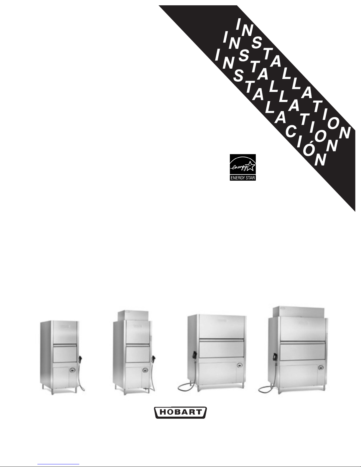
Carefully unpack the machine from the pallet.
1. Remove the shipping brackets from the machine/pallet.
Fig. 1
2. Remove the bottom pallet boards. This can be done using a pallet jack.
Proper care and personal equipment should be used when when handling
wood with exposed nails.
Fig. 2 Fig. 3
3. Screw out the feet.
4. With machine resting on the feet, slide pallet out from underneath the machine.
NOTE: On the PW20 machine the pallet sides might need to be removed to
make this easier.
– 5 –
Page 6
Removing ER Section if Necessary
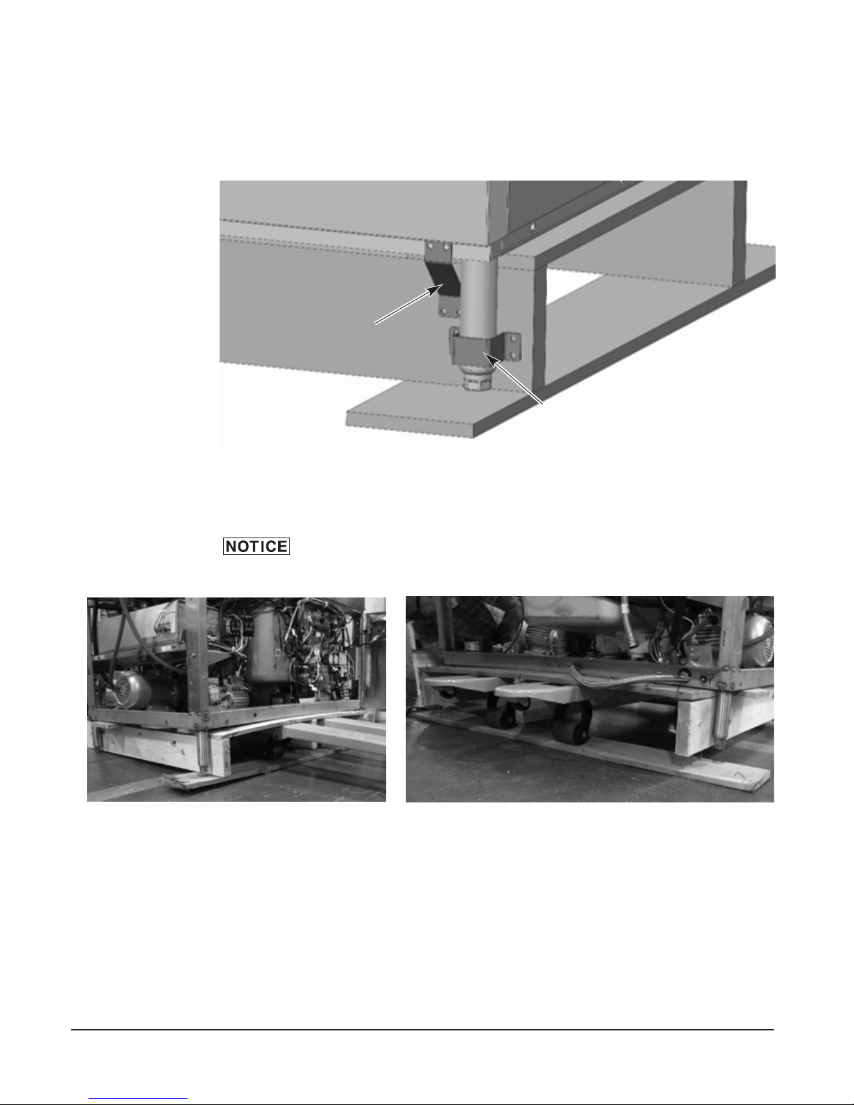
Disconnect the electrical power to the machine and follow
lockout / tagout procedures. There may be multiple circuits. Be sure all circuits
are disconnected.
NOTE: One ER unit is shown in the following steps. If removing both from
PW20 Advansys, repeat steps 2 through 10 for each side.
1. Disconnect incoming water hose at supply connection.
Fig. 4
NOTE: Drain out any excess water in hose.
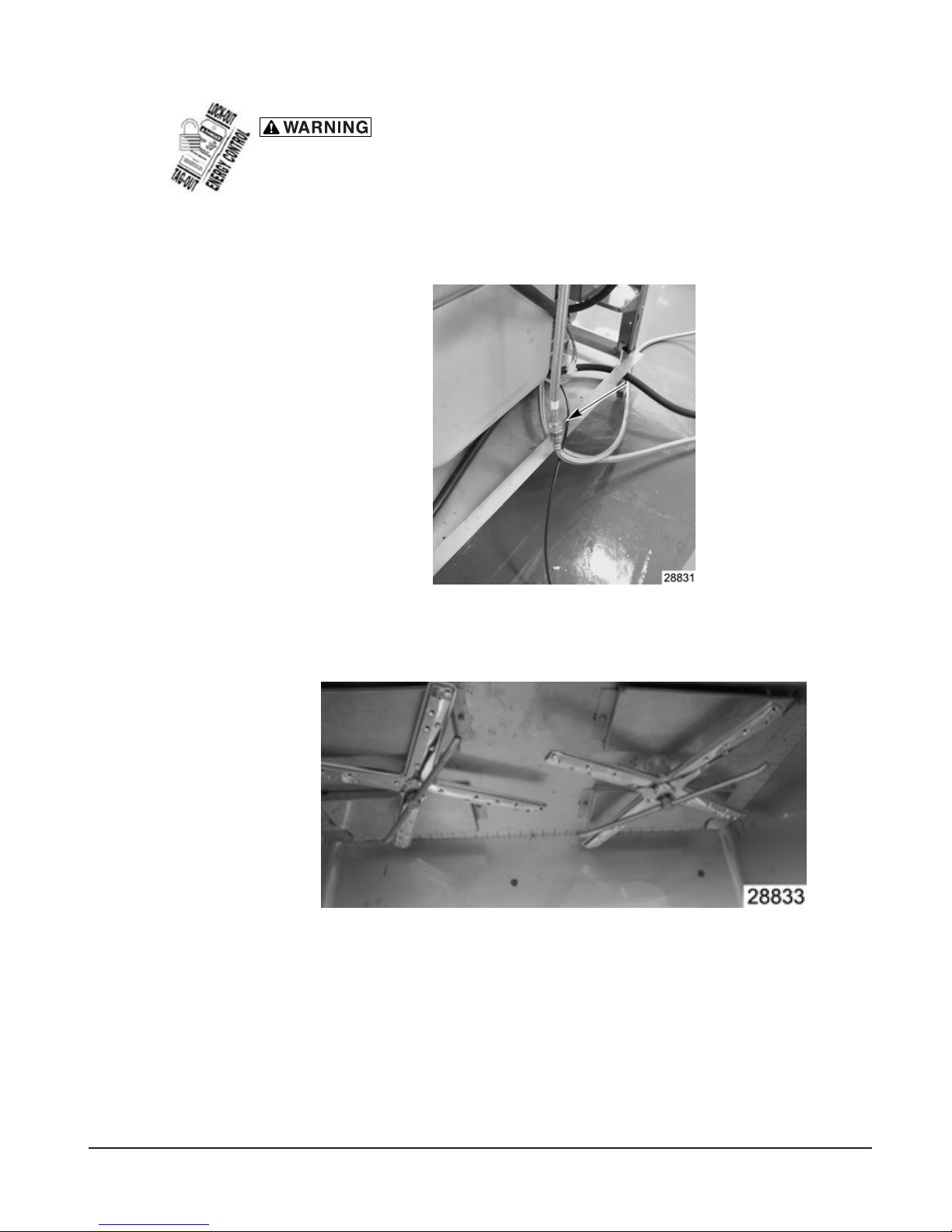
2. Remove upper wash and rinse arms.
Fig. 5
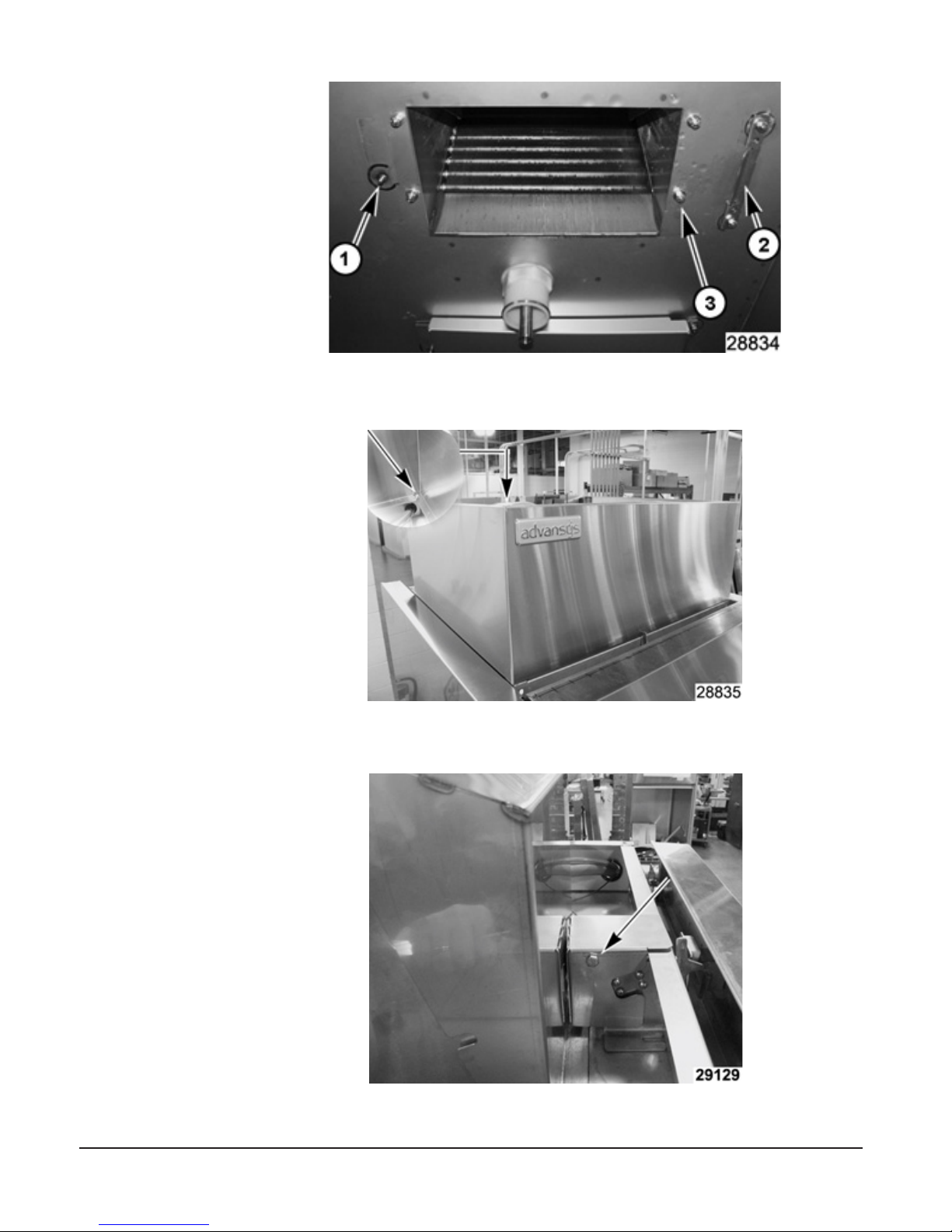
3. Remove bafes. (located under wash and rinse arms).
a. Remove bolt (1).
b. Side bafe to side to free from holding bracket (2) from opposite side of bafe.
c. Remove (Qty 4) nuts (3) that are holding ER assembly from inside wash area.
– 6 –
Page 7
2. Remove shroud.
3. Remove door lock assembly cover.
Fig. 6
Fig. 7
Fig. 8
– 7 –
Page 8
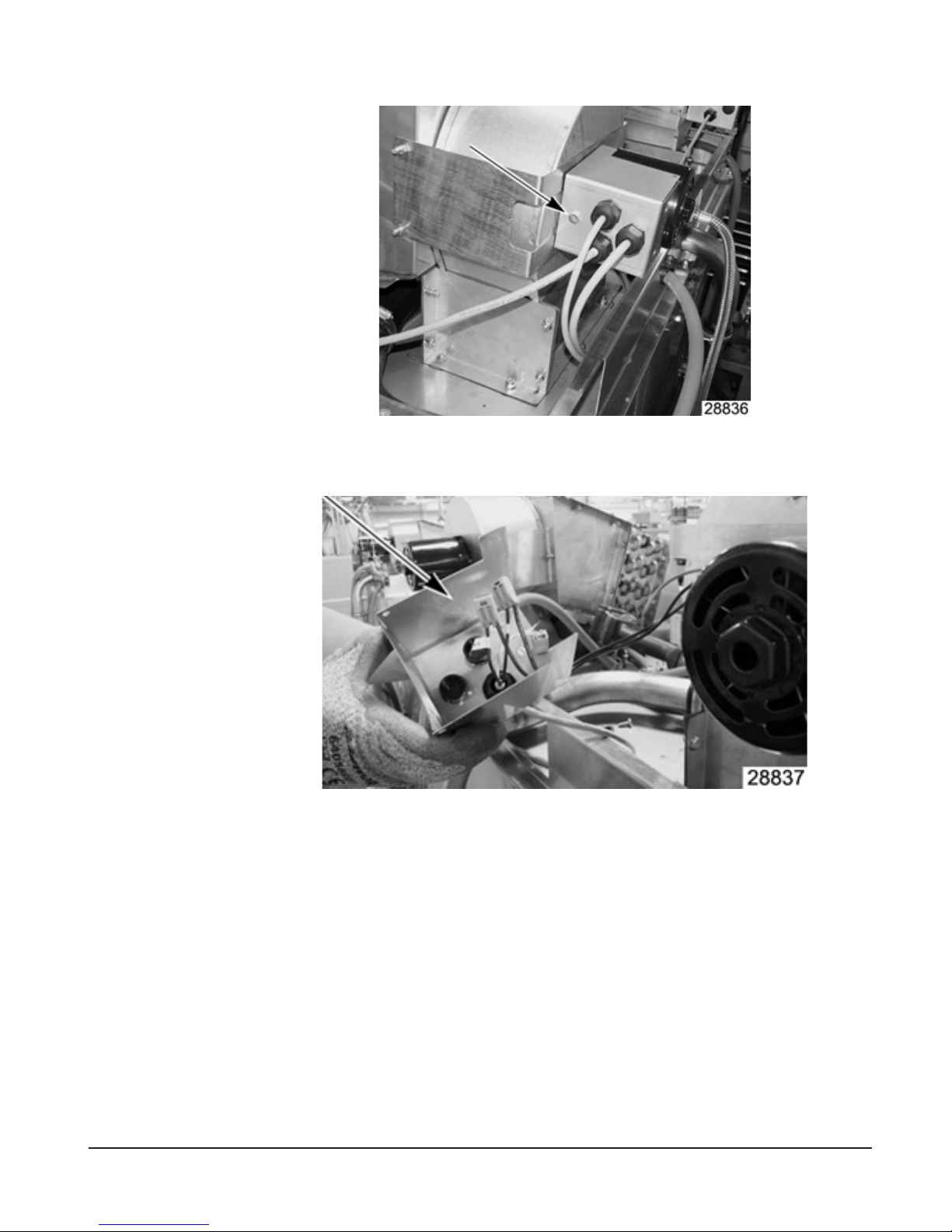
4. Remove motor junction box cover.
Fig. 9
5. Label motor wires for reconnecting later.
6. Disconnect motor wires.
Fig. 10
– 8 –
Page 9
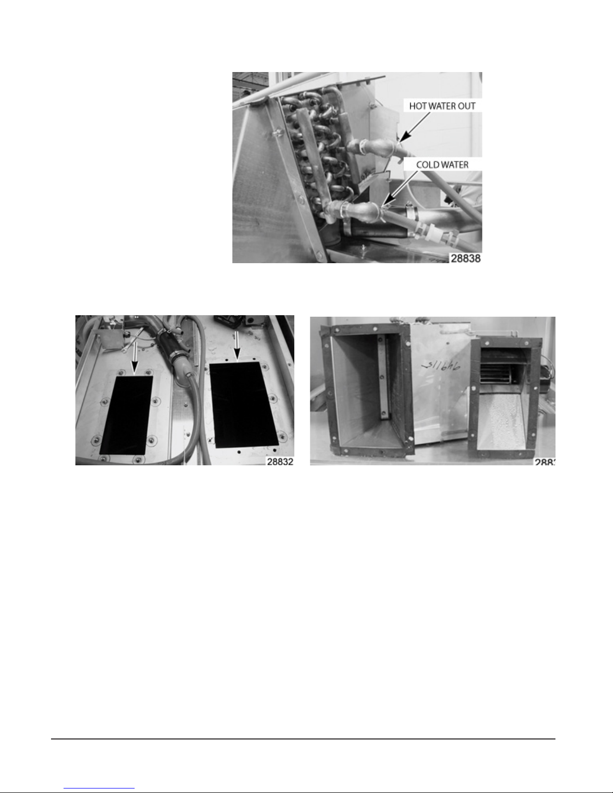
7. Disconnect water hoses connected at ER assembly.
Fig. 11
8. Remove (Qty 13) mounting nuts around ER assembly.
Fig. 12 Fig. 13
– 9 –
Page 10

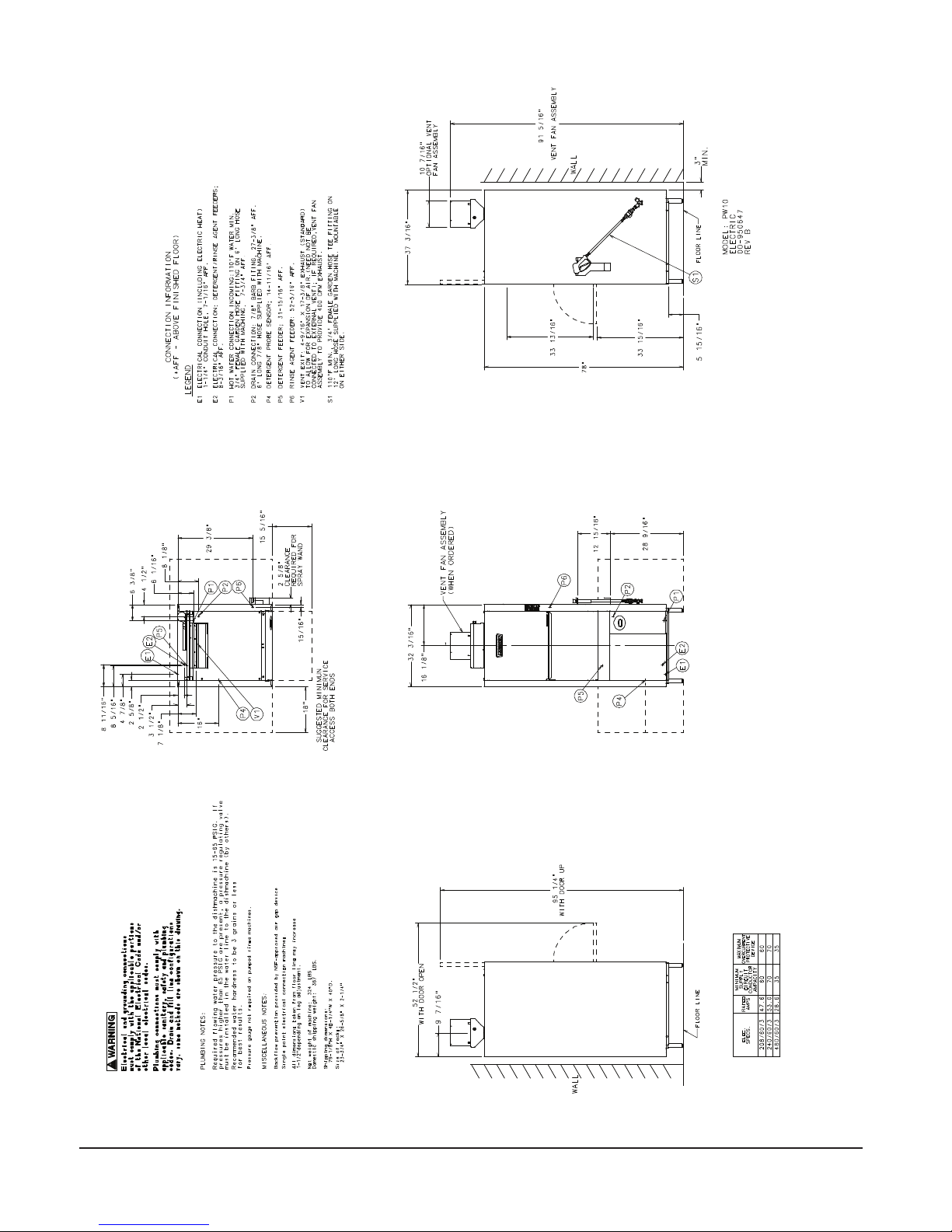
9. Lift ER assembly off of machine.
10. Reverse procedure to install.
NOTE: If ER units were removed to get thru a door opening, when re-installing,
remove, clean surface, and install new foam tape to the housing to ensure a
proper seal.
INSTALLATION CODES
Installation must be in accordance with state and local codes, and the National
Electrical Code ANSI/NFPA70 (latest edition). In Canada, the installation code is
CSA 22.1 (latest edition).
LOCATION
Set the machine in place after the nal oor covering is installed. Make sure the
machine is level before making any plumbing connections. Allow at least 3" at the
rear and 18" at the sides of the machine for service access. Allow 16" in front of the
machine for the door to lower and sufcient additional space for the operator to work.
Fig. 14
– 10 –
Page 11
OPTIONAL
PW10
– 11 –
Page 12
76-7/16”
PW10eR
– 12 –
Page 13
OPTIONAL
PW20
– 13 –
Page 14
76-5/8”
PW20eR
– 14 –
Page 15

PLUMBING CONNECTION(S)
applicable portions of the National Electrical Code (NFPA No. 70, CSA 22.1
latest edition) and/or other local electrical codes.
Water Requirements
Proper water quality can improve ware washing performance by reducing spotting,
enhancing effectiveness of labor and extending equipment life. Water conditions
vary from one location to another. The recommended proper water treatment for
effective and efcient use of this equipment will also vary depending on the local
water conditions. Ask your municipal water supplier for details about your local water
conditions prior to installation.
Recommended water hardness is 3 grains of hardness per gallon or less. Higher
hardness may cause excessive formation of lime scale. Water hardness above 3
grains per gallon requires water treatment. Water treatment has been shown to
reduce costs associated with machine cleaning, reduce deliming of the dishwasher,
and reduce detergent usage in the dishwasher. Chlorides must not exceed 50 ppm.
require an iron lter. High chloride levels in the water supply can cause
pitting and may require a chloride removal system. Contact your local water
treatment professional for proper water treatment.
Electrical and grounding connections must comply with
High iron levels in the water supply can cause staining and may
Sediment may require a particulate lter. Dissolved solids may require water treatment
such as a water softener, reverse osmosis system, etc. Contact your local water
treatment professional for proper water treatment.
If an inspection of the dishwasher or booster heater reveals lime buildup after the
equipment has been in service, water treatment is recommended. If a water softener
is already in place, ensure there is a sufcient level of salt. Contact your local Hobart
Service ofce for specic recommendations.
Water Supply Connection
The water supply line should be a ¾” male garden hose (supplied by others).
The plumber connecting this machine is responsible for making certain that water
lines are THOROUGHLY FLUSHED OUT BEFORE connecting to the dishwasher.
This "ush-out" is necessary to remove all foreign matter, such as chips (resulting
from cutting or threading of pipes) pipe joint compound from the lines; or, if soldered
ttings are used, bits of solder or cuttings from the tubing. Debris, if not removed,
may lodge in the dishwasher's plumbing components and render them inoperative.
Manual valves or solenoid valves fouled by foreign matter and any expenses resulting
from this fouling are NOT the responsibility of the manufacturer and associated
repair costs are not covered under warranty.
– 15 –
Page 16
Water supply requirements are as follows:
WATER SUPPLY REQUIREMENTS
Model Supply Temperature
PW10 Hot Water 110°F Minimum
PW10eR Cold Water 55°F Minimum, 80°F Maximum
Hot Water 110°F Minimum
PW20 Hot Water 110°F Minimum
PW20eR Cold Water 55°F Minimum, 80°F Maximum
Hot Water 110°F Minimum
PW10eR and PW20eR models require both a cold water supply connection and a
hot water supply connection.
On PW10eR and PW20eR installations, the cold water supply must
not exceed 80°F (27°C) for proper operation. Optimal results are obtained
when cold water supply temperature is below 65°F (18°C). For best results,
it may be necessary to use ½” pipe for cold water pipe size and minimize
the distance between the dishwasher and the entrance into the building.
Pipe insulation will also improve results.
If cold water supply temperature is consistently above 80°F (27°C) or if excessive
water vapor or steam is entering the room after the condensing cycle is complete,
contact Hobart Service to increase condensing time.
Required owing water pressure to the dishmachine is 15-65 PSIG. If pressures
higher than 65 PSIG are present, a pressure regulating valve must be installed in
the water line to the dishmachine (by others). If owing pressure is less than 15
psi, improper machine operation may result. All PW models are equipped with a
pumped rinse system; therefore, a water pressure gauge is not required and is not
supplied with the machine.
The water pressure regulator must have a relief bypass. Failure to
use the proper type of pressure regulator may result in damage to the unit.
A manual shutoff valve (not supplied) should be installed upstream of the ll hose
to accommodate servicing the machine.
It is recommended that a line strainer (not supplied) be installed in the supply line
between the manual shutoff valve (not supplied) and the connection point on the
machine. Make plumbing connections with ½” minimum copper piping OD (¾”
recommended), with a ¾” male garden hose tting (not supplied). See installation
diagrams, pages 11-14.
– 16 –
Page 17
Plumbing Connections
Plumbing connections must comply with applicable sanitary,
safety, and plumbing codes.
Drain
A drain hose, 7⁄8" inside diameter and 6' long, is provided. This should be securely
plumbed into a drain. Use care not to kink hose. See installation diagrams, pages
11-14. Drain must have a minimum ow capacity of 18 gallons per minute for PW10/
PW10eR and 26 gallons per minute for PW20/PW20eR.
Venting Requirements (PW10 / PW20)
Type I or type II canopy hoods are recommended. Hoods must be installed according
to the manufacturer's instructions. Make-up air must be provided so that the exhaust
ow rate results in a negative building pressure in the room where the unit is located
(more exhaust air than outside air). Factory-built hoods not tested to UL standard
710 and custom-built hoods must comply with the following specications: Stainless
steel should have a minimum thickness of 0.037 in. (0.94 mm) [No. 20 Gauge] or
copper sheet weighing at least 24 ounces per square foot (7 Kg/m2); the hood
must be secured in place by noncombustible supports and must meet the RATE of
EXHAUST FLOW CALCULATIONS.
Make sure the installation meets the local code for your area.
Rate of Exhaust Flow Calculations (FIG. 14)
Based on the 2015 International Mechanical Code.
Fig. 15
– 17 –
Page 18

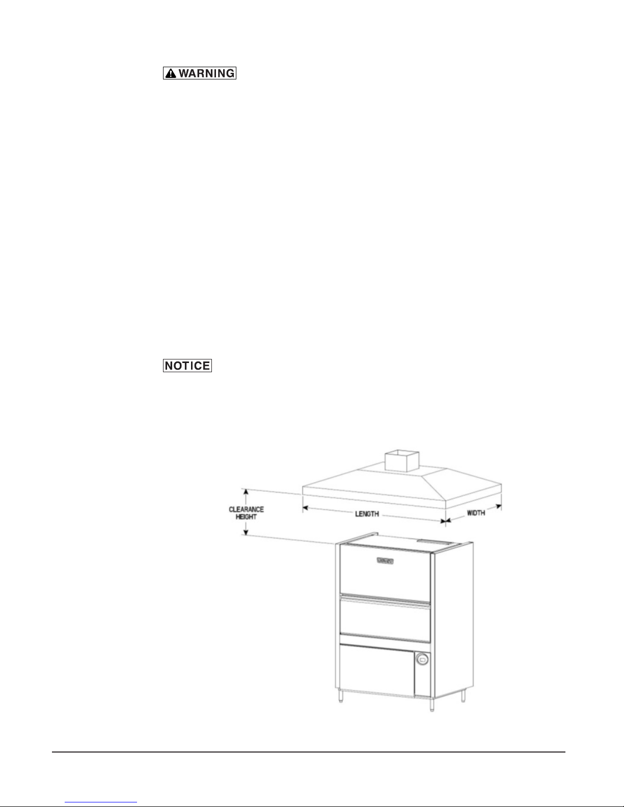
Canopy Size and Location
The inside lower edge of canopy-type type I and II commercial hoods shall overhang
or extend a horizontal distance of not less than 6 inches (152 mm) beyond the edge
of the top horizontal surface of the appliance on all open sides. The vertical distance
between the front lower lip of the hood and such surface shall not exceed 4 feet
(1219 mm) with a minimum of 1 foot (305 mm).
18” min overhang of the front opening.
The RATE of air ow required for a vent hood is a minimum of 100 CFM per linear
foot of hood length.
Rate of Exhaust Flow Calculations
Based on the 2015 International Mechanical Code.
The minimum net airow for Type II hoods used for dishwashing appliances shall
be 100 cfm per linear foot of hood length. The net quantity of exhaust air shall be
calculated by subtracting any airow supplied directly to a hood cavity form the total
exhaust ow rate of a hood.
Models PW10eR and PW20eR do not require a Type II vent hood. According to
507.3 of the 2015 IMC, Type II hoods are not required where the heat and moisture
loads is incorporated in the HVAC system design. See Table A for heat dissipation
or heat gain to space.
Model Voltage
PW10 208V 13,600 6,000
PW10 240V / 480V 16,800 7,300
PW10eR 208V 16,200 10,000
PW10eR 240V / 480V 20,100 12,300
PW20 208V 17,100 7,500
PW20 240V / 480V 20,400 8,900
PW20eR 208V 20,400 12,500
PW20eR 240V / 480V 24,300 14,800
Chemical Feeder Installations
This machine must be operated with an automatic detergent feeder, including a
visual means to verify that detergents are delivered or a visual or audible alarm to
signal if detergents are not available for delivery to the washing system. Chemical
feeders are supplied by others. For electrical connection, refer to Equipment
Connections, page 21.
Table A
HEAT DISSIPATION
Latent Heat
(BTU/HR)
Sensible Heat
(BTU/HR)
– 18 –
Page 19

Detergent Feeder (Optional By Others)
If installing a detergent feeder (by others), remove cap to expose 7/8” diameter
hole at rear of machine.
Rinse Agent Feeder (Optional By Others)
If a rinse agent feeder (by others) is being installed, remove the 1/8" NPT pipe
plug(s) to access the tapped hole in the rinse tee on the right side of the machine
(PW10/PW10eR) and on the back of the machine (PW20/PW20eR). There are 2
rinse tees for the PW20/PR20eR machines.
Delime Feeder (standard) on Advansys models only (PW10eR/ PW20eR)
A delime feeder with tubing and standpipe is provided to automatically dispense
delime agent when needed.
Vent Exit (PW10 / PW20)
A vent exit (4-9/16 " x 17-3/8") is provided in the top of the machine to allow for
expansion of air. It must not be directly connected to an external vent.
Vent Fan Control (Standard); Power Vent Fan (Optional) PW10/PW20
The Vent Fan Control provides switching for a vent fan (by others). The vent hood
comes on when the PW10/20 is on and goes off when the PW10/20 is off. The
Power Vent Fan option exhausts moist air from the chamber after the rinse cycle is
nished. The Power Vent fan may be selected to operate for 40, 60 or 80 seconds.
The Power Vent Fan kit (eld installed only) extends upward 12 ¼” above the vent
exit (13 5/16” above the top of the wash chamber) and terminates in a round duct
connection for a 101/4" O.D. duct.
Install power vent fan kit using a maximum 60 ft of 10” diameter straight duct; or, 50
ft straight and two (2) 90°elbows, or equivalent. Distances greater than the stated
maximum lengths may reduce venting efciency.
ELECTRICAL CONNECTION(S)
applicable portions of the National Electrical Code (NFPA No. 70, latest edition)
and/or other local electrical codes.
lockout / tagout procedures. There may be multiple circuits. Be sure all circuits
are disconnected.
Electrical and grounding connections must comply with
Disconnect the electrical power to the machine and follow
– 19 –
Page 20
Connect incoming power to the control box in accordance with the wiring diagram
located on the back of the front trim panel.
Volts/Hz/ph Rated Amps Circuit Size* Amps
208/240/60/3 47.6 / 53.0 60 / 70
480/60/3 28.6 35
Volts/Hz/ph Rated Amps Circuit Size* Amps
208/240/60/3 58.6 / 64.0 70 / 80
480/60/3 35.0 45
* Minimum Circuit Size / Maximum Protective Device (Amps) compiled in accordance
with the National Electrical Code (NFPA 70), latest edition.
** For supply connection, use wires suitable for at least 90°F or equivalent
Rotation of Pump Motor(s)
ELECTRICAL DATA
PW10 / PW10eR (Single Point Connection)
PW20 / PW20eR (Single Point Connection)
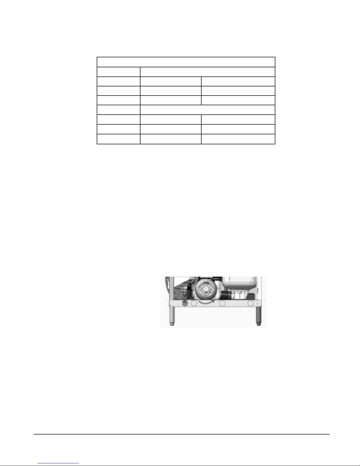
Before using the machine, check the pump motor rotation to be sure it is rotating
in the right direction.
PW10 / PW10eR
From the front of the machine, the motor should rotate clockwise. Looking from the
rear of the machine, the correct rotation is counterclockwise. Inspection is easiest
from the rear of the machine using a ashlight and mirror to check the motor fan in
the rear. Be aware that the mirror will reverse the perceived direction.
PW10 (Rear View)
Fig. 16
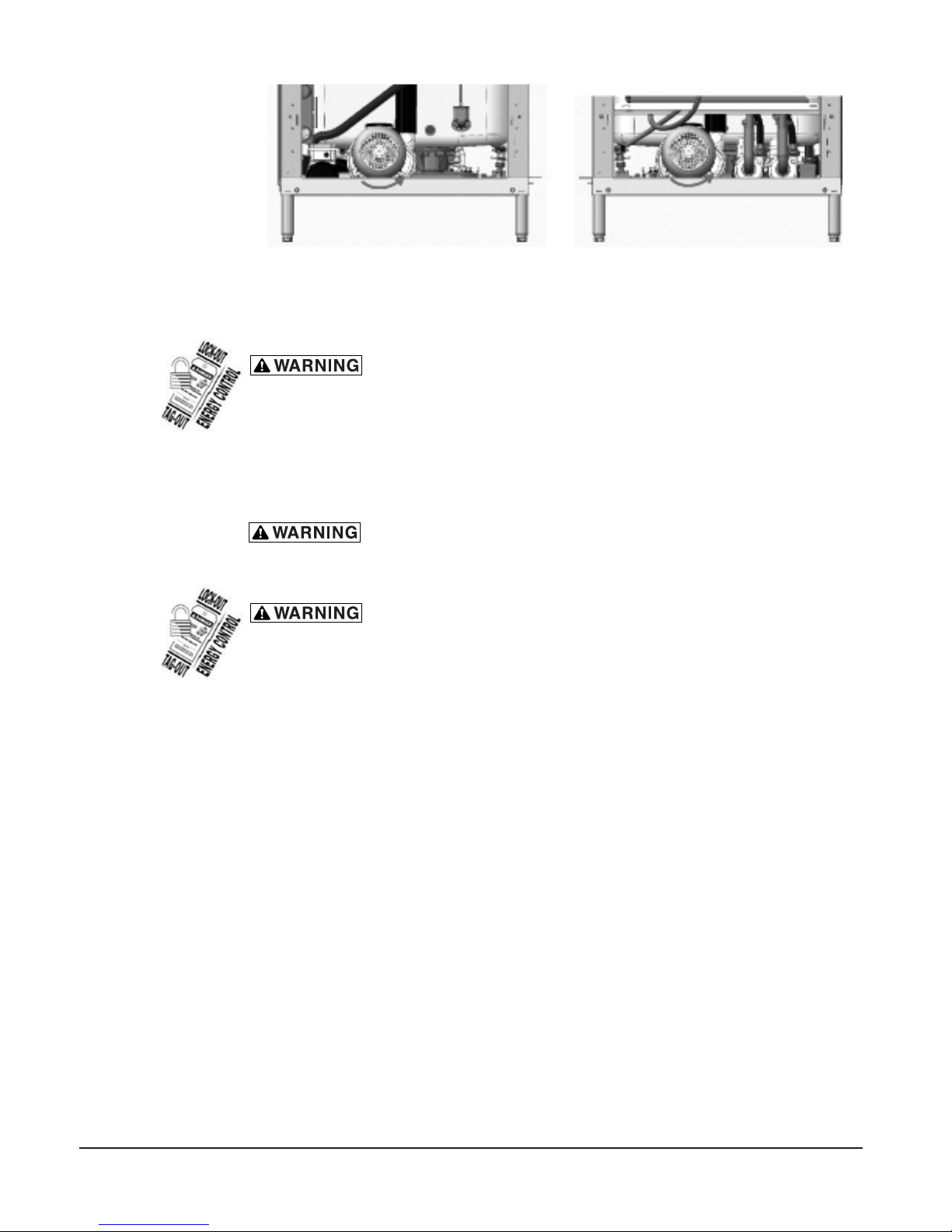
PW20 / PW20eR
Pump motor 1 – Looking from the right side of the machine, the correct rotation
is counterclockwise. Inspection is easiest from the right side using a ashlight to
check the motor fan on the rear of the motor.
Pump motor 2 – Looking from the left side of the machine, the correct rotation is
counterclockwise. Inspection is easiest from the left side using a ashlight to check
the motor fan on the rear of the motor.
– 20 –
Page 21
If the pump motor(s) is/are rotating in the wrong direction, follow this procedure.
lockout / tagout procedures. There may be multiple circuits. Be sure all circuits
are disconnected.
Reverse any two of the three incoming line wires (not the ground wire). Reconnect
and recheck rotation of pump motor.
EQUIPMENT CONNECTIONS
applicable portions of the National Electrical Code (NFPA No. 70, latest edition)
and/or other local electrical codes.
lockout / tagout procedures. There may be multiple circuits. Be sure all circuits
are disconnected.
Vent Fan Control
PW20 (right view) PW20 (left view)
Fig. 17
Disconnect the electrical power to the machine and follow
Electrical and grounding connections must comply with
Disconnect the electrical power to the machine and follow
The vent fan control feature is standard on PW10 and PW20 models. This feature is
not available on PW10eR and PW20eR models. The vent fan control relay provides
switch contacts only and does not provide power to the vent fan motor. The rating
for a vent fan control relay connected to terminals VFC1 and VFC2 is 1.5 amps at
supply voltage. When the prepwasher is connected to the vent fan, the vent fan is
switched on when the prepwasher is on, and off when the prepwasher is off.
Detergent Feeder
The maximum rating for a detergent dispenser connected to DPS1 and DPS2 is 1.5
amps at line voltage. Refer to Chemical Feeder Installations, page 18.
Rinse Aid Feeder
The maximum rating for a rinse aid dispenser connected to RPS1 and RPS2 is 1.5
amps at line voltage. Refer to Chemical Feeder Installations, page 18.
– 21 –
Page 22
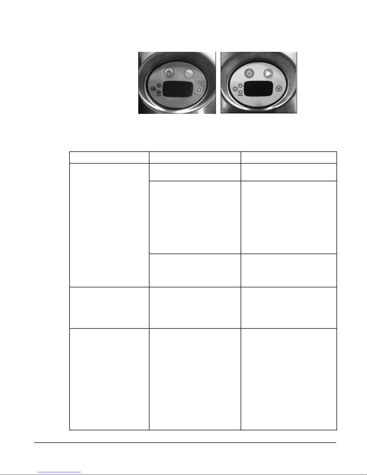
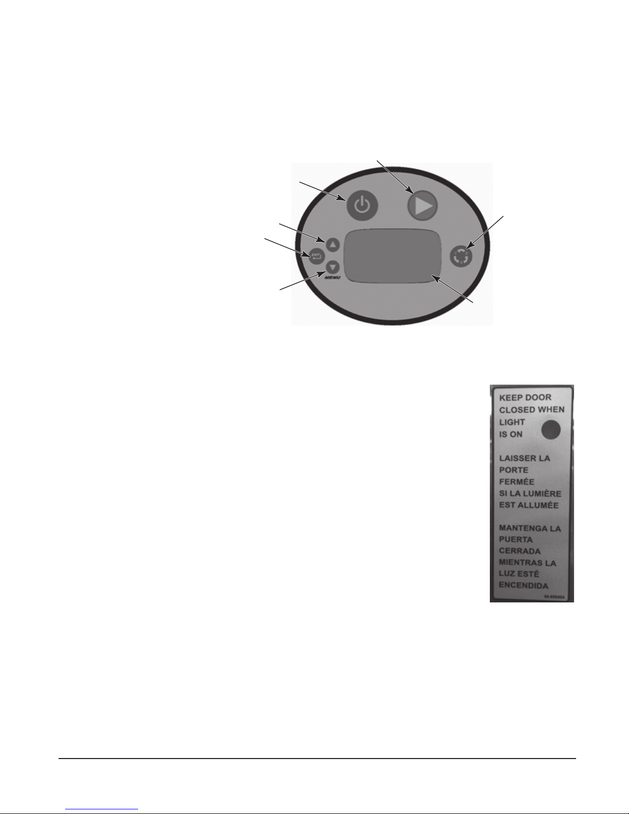
CONTROLS
OPERATION
Fig. 18
Operating the PW Prep Washer
DO THIS DISPLAY SHOWS REMARKS
Press ON Model number Dishwasher performs self-
check. This takes 5 seconds.
Open door; slide rack
out to load ware. When
loading is complete, slide
rack into dishwasher.
Close door.
Press WASH (Green
Arrow).
FILL and ll icon lit; sump
temperature displayed when
machine is lling.
WARMING UP and warming
up icon are displayed when
booster is preheating on
models. This preheat could
take up to 25 minutes.
During ll, sump temperature
is displayed.
READY lit and sump
temperature displayed.
WASH and wash icon lit;
sump temperature displayed
during wash cycle.
Dishwasher lls with water.
If door is opened during ll
cycle, ll will stop. After door is
closed, the process continues
where it stopped.
When lled, machine will
maintain an idle state. Heat is
maintained in both sump and
booster.
Detergent contacts will be
activated during wash cycle.
Rinse contacts turned on
during rinse cycle for external
dispenser.
Machine initiates a wash and
rinse cycle.
RINSE and rinse icon lit;
rinse temperature displayed
during rinse cycle.
CONDENSE and condense
icon lit (Advansys models
only).
EXHAUST (base models with
Vent Fan Control only).
– 22 –
If door is opened during wash,
rinse, or drain cycle, cycle will
continue at point where door
was opened upon closing door.
If POWER is pressed during
cycle, machine will drain and
shut down
Page 23

DO THIS DISPLAY SHOWS REMARKS
When cycle is complete,
reload machine for next
READY lit and sump
temperature displayed.
wash/rinse cycle; or, if
not in use, machine will
maintain idle mode.
At the end of the day,
press POWER.
DRAIN and SHUTDOWN IN
PROGRESS are displayed;
then the machine shuts
down.
SELECT WASH CYCLE and press START
CYCLE DESCRIPTION
2 A 2-minute wash cycle is followed by a 10 or
12-second fresh water rinse
(Advansys models have 99-190 second condensing
cycle).
4 A 4-minute wash cycle is followed by a 10 or
12-second fresh water rinse.
(Advansys models have 99-190 second condensing
cycle).
6 A 6-minute wash cycle is followed by a 10 or
12-second fresh water rinse.
(Advansys models have 99-190 second condensing
cycle).
All rinse cycles are followed by a 5 second pause.
Minimum Wash tank temperature is 150°F. Minimum Rinse temperature is 180°F.
Machine will drain and shut
down if the four hour idle shutdown time is reached.
When POWER key is pressed,
machine will drain and shut
down.
PROGRAMMING
Manager Mode Programing
The PW series prep washer’s microprocessor allows customization options for
machine operation. To activate or change these features, the programming edit
mode must be entered.
The manager programming mode requires a MANAGER CODE to be entered to
access the options listed in the PARAMETER MENU. The manager codes is 1001.
– 23 –
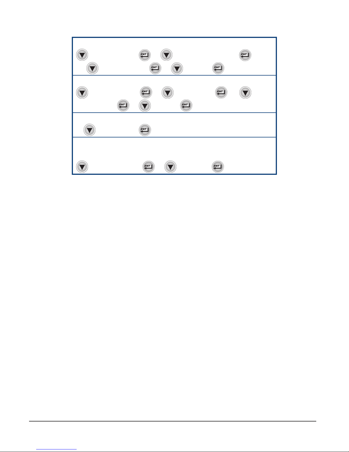
Page 24
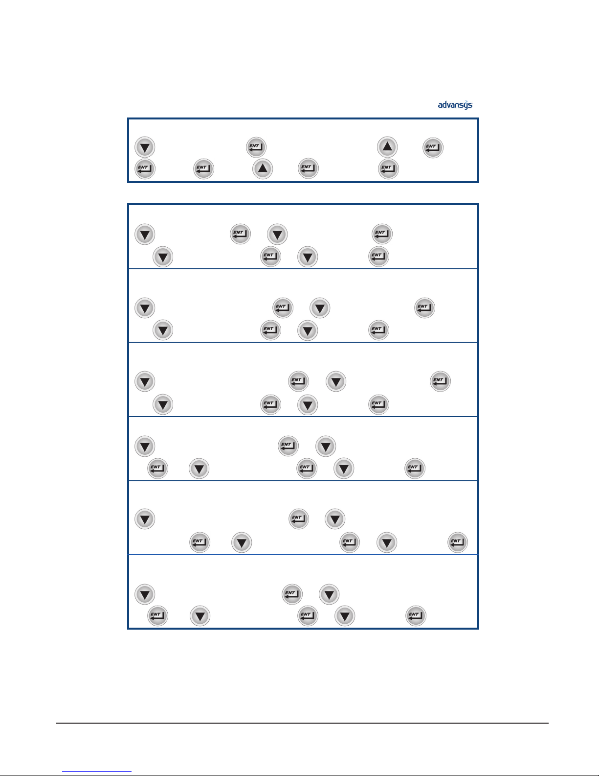
Manager Mode
PW PW
CHANGING PARAMETERS ENTER MANAGER SECURITY CODE: 1001
MANAGER MENU
➜
Programming Card
➜ ➜
ENTER SECURITY CODE
➜
(for 1)
➜
(for 0)
➜
(for 0)
➜
(for 1)
Edit Parameters
CHANGING PARAMETERS IS REQUIRED TO CHANGE ALL CODES BELOW
DELIME enables or disables the delime reminder alert.
OR
➜
until DELIME
➜
➜ ➜
until E XIT MENU
➜ ➜
to enable or disable
until E XIT
➜
➜
LOW TEMP ALARMS enables or disables alert indicating that the final rinse temperature has
been below the minimum temperature for a period of time.
OR
➜
until LOW TEMP A LARMS
➜
until E XIT MENU
➜ ➜
➜ ➜
to enable or disable
until E XIT
➜
➜
END CYCLE AUDIO ALERT enable or disable the unit creating an audio alert at the end of
each wash cycle.
OR
➜
until END CYCLE AUDIO ALERT
➜
until E XIT MENU
➜ ➜
➜ ➜
to enable or disable
until E XIT
➜
➜
TEMPERATURE UNITS allows the choice of Fahrenheit or Celsius.
until TEMPER ATURE UNITS
➜
➜ ➜
to choose Fahrenheit or Celsius
➜
OR ➜
until E XIT MENU
➜ ➜
until E XIT
➜
DIRTY WATER INDICATOR disables or gives a choice of how many cycles the machine will
run between dirty water alert and refresh cycles.
➜
or 60 cycles
until DIRTY WATER INDICATOR
➜
OR ➜
➜ ➜
until E XIT MENU
to Disable, 20 cycles, 40 cycles,
➜ ➜
until E XIT
➜
ENERGY SAVER MODE disables or gives choice of how many hours before the unit will
stay on before entering energy saving mode.
until ENERGY SAVING MODE
➜
➜
OR ➜
➜ ➜
until E XIT MENU
➜ ➜
to Disabled, 1 Hour, 2 Hours, or 3 Hours
until E XIT
➜
– 24 –
Page 25
LANGUAGE allows the choice of English, French or Spanish language.
OR
until LANGUAGE
➜
until E XIT MENU
➜
➜ ➜
➜ ➜
to English, French or Spanish
until E XIT
➜
➜
WASH PROGRAM allows the customization of total run time.
until CYCLE TIME
➜
until E XIT MENU
➜ ➜
➜ ➜
until E XIT
EXIT MENU TO MAIN MANAGER MENU
until E XIT MENU
➜
➜
to choose cycle,
➜
➜
OR
➜
DELIME NOW allows for a single delime cycle to be run from the menu at anytime.
Note: this operation takes up to 1 hour 45 minutes depending on conditions. The machine will automatically
shut down at the end of delime cycle.
until DELIME NOW
➜
➜ ➜
to YES or NO
➜
(this will exit menu)
– 25 –
Page 26
Programming Instructions
All customization is performed through the on-screen menu using the UP arrow,
MENU/DOWN arrow, and ENT keys located on the keypad on the lower right of
the machine (Fig. 4).
WASH
POWER
MENU/DOWN ARROW
Menu Display Prompts
The following prompts are used inside the menus:
• The UP arrow and MENU/DOWN arrow keys are used
to change parameter values and to navigate the menu.
• The ENT key is used to accept a value, to perform a
specic action, or to enter a submenu.
On PW10eR and PW20eR Advansys models, the door is locked
and must remain closed until the condensing cycle is completed.
During the condense cycle a countdown icon shows the remaining
cycle time. When the cycle is nished and the condense icon
disappears and the condensing cycle light turns off and the door
is unlocked. Open the door and pull out the rack to remove the
clean ware. Load soiled ware onto rack and push rack into the
machine. Close the door.
UP ARROW
ENTER
CYCLE
DISPLAY
Fig. 19
– 26 –
Page 27
Recommended Condense Time
(Based on Incoming Water Temperature)
Incoming
Water Temp
Rinse
Time
PW10eR PW20eR
Condense
Time
Racks per
Hour
Rinse
Time
Condense
Time
°F (°C)
(Sec.)
(Sec.)
(2 min. cycle)
(Sec.)
(Sec.)
60 (16) – 64 (18) 10 99 13 12 98 13
64 (18) – 72 (22) 12 119 12 14 114 12
72 (22) – 80 (27) 14 139 11 16 131 11
80+ (27+) 16 158 10 18 147 10
For Advansys models only – If excessive amounts of steam or water vapor exit the
machine after condensing cycle light goes out and door is opened, incoming cold
water temperature may be too high.
Contact Hobart Service to adjust the rinse and condense times according to the
adjustment table. Increasing cycle time will increase water consumption and
decrease the racks per hour, but should reduce the water vapor entering the room.
General Operating Instructions
Keep the prep washer clean to provide best results. Do not allow foreign
objects to enter the unit, especially metallic contaminants.
Racks
per Hour
(2 min. cycle)
CLEANING
Do not wash aluminum utensils in the prep washer. The caustic detergent and high
water temperature will cause aluminum oxide formation (black). Copper utensils
may require polishing to remove oxide formation after exposure to utensil washer
cleaning for a period of time. Stainless steel utensils should clean quickly and easily
if the food soil is not baked on.
It may be necessary to scrub or prewash some hard-to-remove substances which
may not come clean in the prep washer with even a 6-minute washing. For stubborn
food soil, a plastic scraper, plastic abrasive pad, nylon bristle brush or sponge with
abrasive surface (Scotch Brite) may be used before washing in the prep washer.
Never use steel wool on ware to be loaded into the prep washer. Use only products
formulated to be safe on stainless steel. Do not use deliming agent on outside of
machine. Rinse items thoroughly after scrubbing to remove metallic debris.
Disconnect the electrical power to the machine and follow
lockout / tagout procedures. There may be multiple circuits. Be sure all circuits
are disconnected.
The prep washer must be thoroughly cleaned at the end of each working shift. Use
only product formulated to be safe on stainless steel. Never use steel wool to clean
machine surfaces.
– 27 –
Page 28
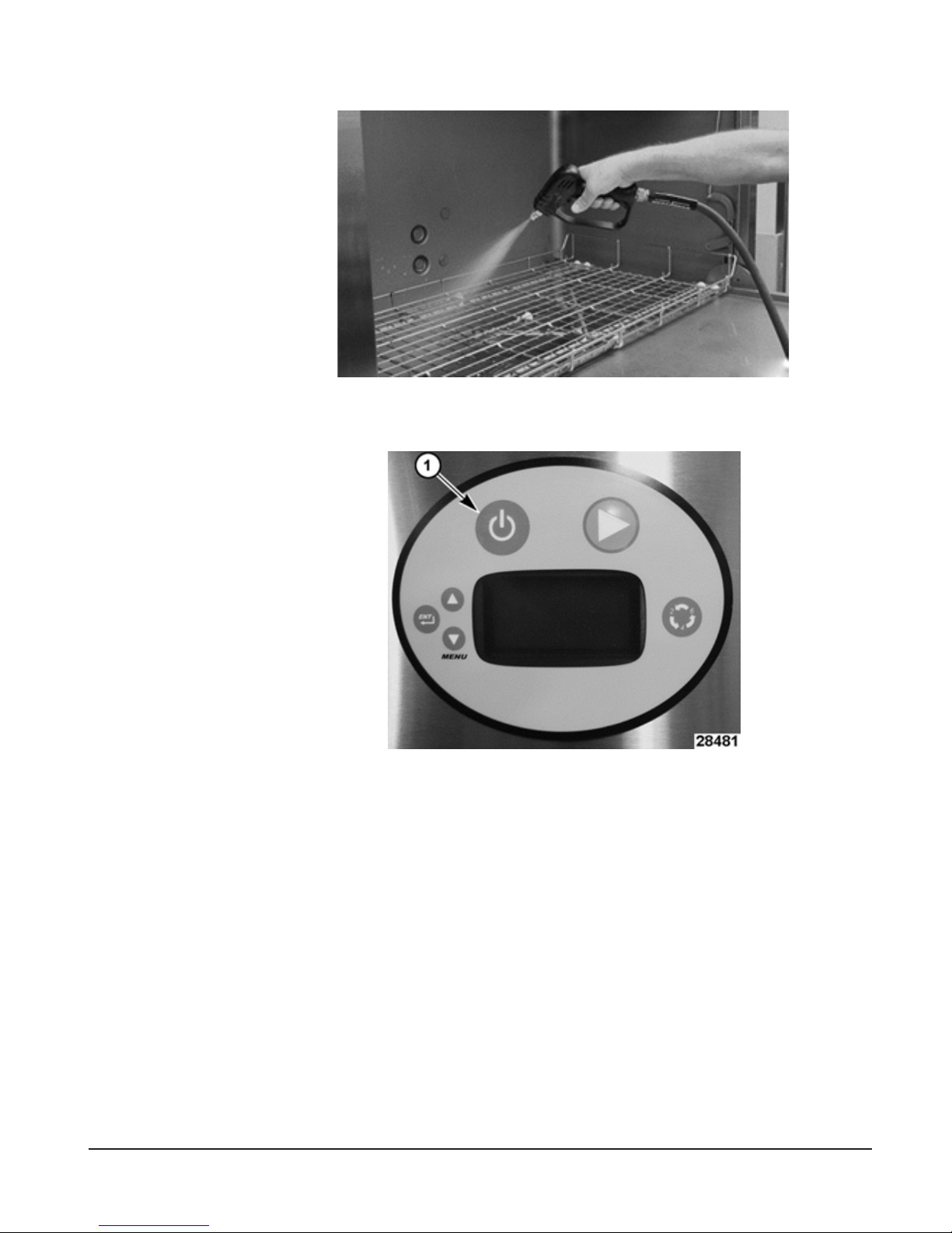
1. Spray down inside of machine with wand (Fig. 20).
Fig. 20
2. Press POWER. The machine will drain. (Fig. 7).
© HOBART 2008
Fig. 21
NOTE: Shutting off the machine causes a full automatic drain, which takes
about 3 minutes for a PW10 and about 3-1/2 minutes for a PW20.
3. Remove tray and racks.
– 28 –
Page 29
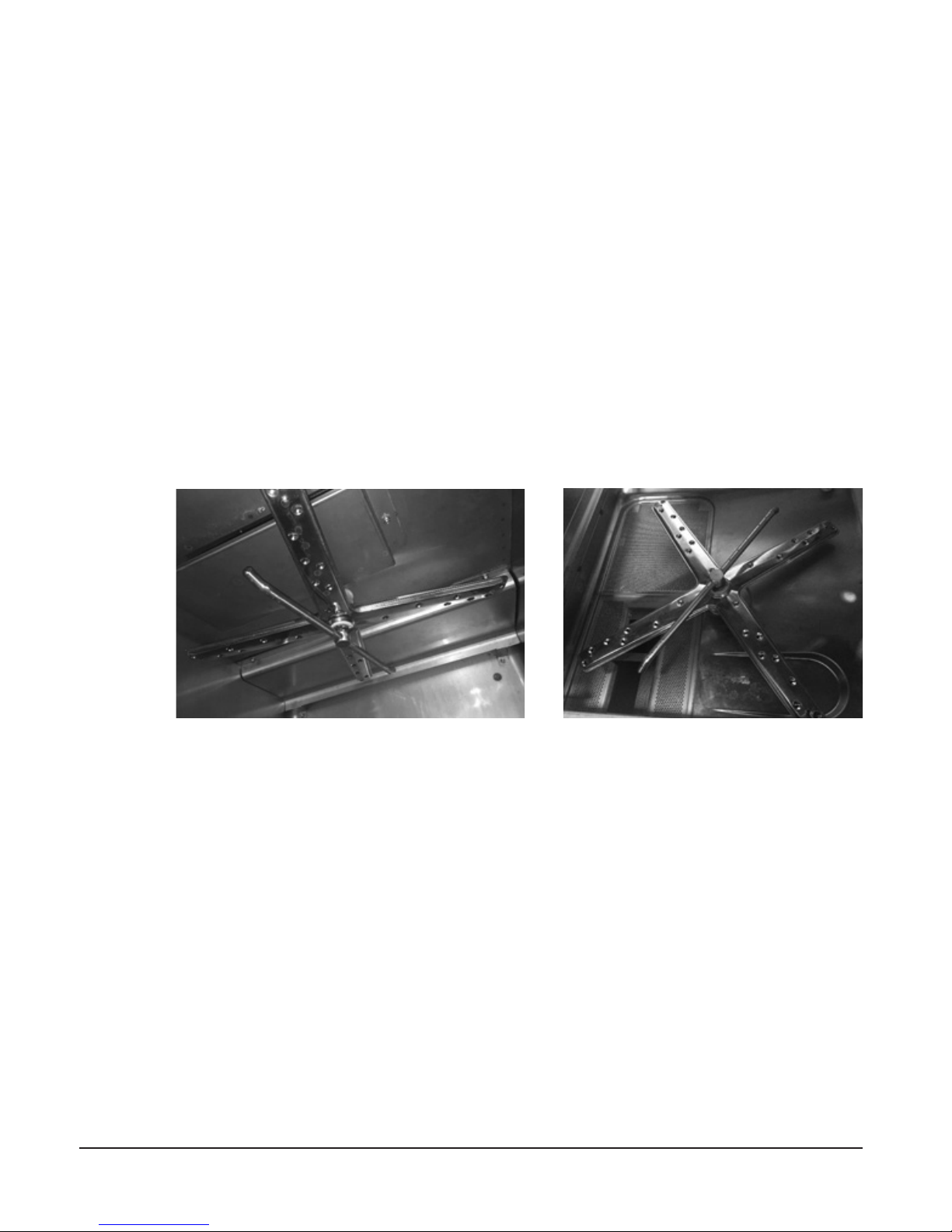
4. The wash and rinse arms are easily removed for cleaning. Make sure that
the wash and rinse arms rotate freely and are free of any obstructions. If any
obstructions are present, remove the wash and rinse arms. Clean the wash and
rinse arms under running water in a sink.
a. To remove upper rinse arm and wash arm (Fig. 22):
i. Unscrew the rinse arm by loosening the tabbed ring at top of rinse arm
ii. Remove both Rinse and Wash arms at the same time, being careful
not to drop these arms.
iii. Reverse the process to replace. Spin arms to make sure they spin
freely.
b. To remove lower rinse arm and wash arm (Fig.23).
i. Unscrew the rinse arm by loosening the tabbed ring at bottom of rinse
arm.
ii. Remove both Rinse and Wash arms at the same time, being careful
not to drop these arms.
iii. Reverse the process to replace. Spin arms to make sure they spin
freely.
Fig. 22 Fig. 23
5. Remove the strainer pans and strainer basket (Fig. 5), and empty into a waste
disposer or garbage container. Wash and rinse strainer pans and strainer basket
thoroughly. Do not bang strainers pan or basket on tables to remove food soil
– 29 –
Page 30
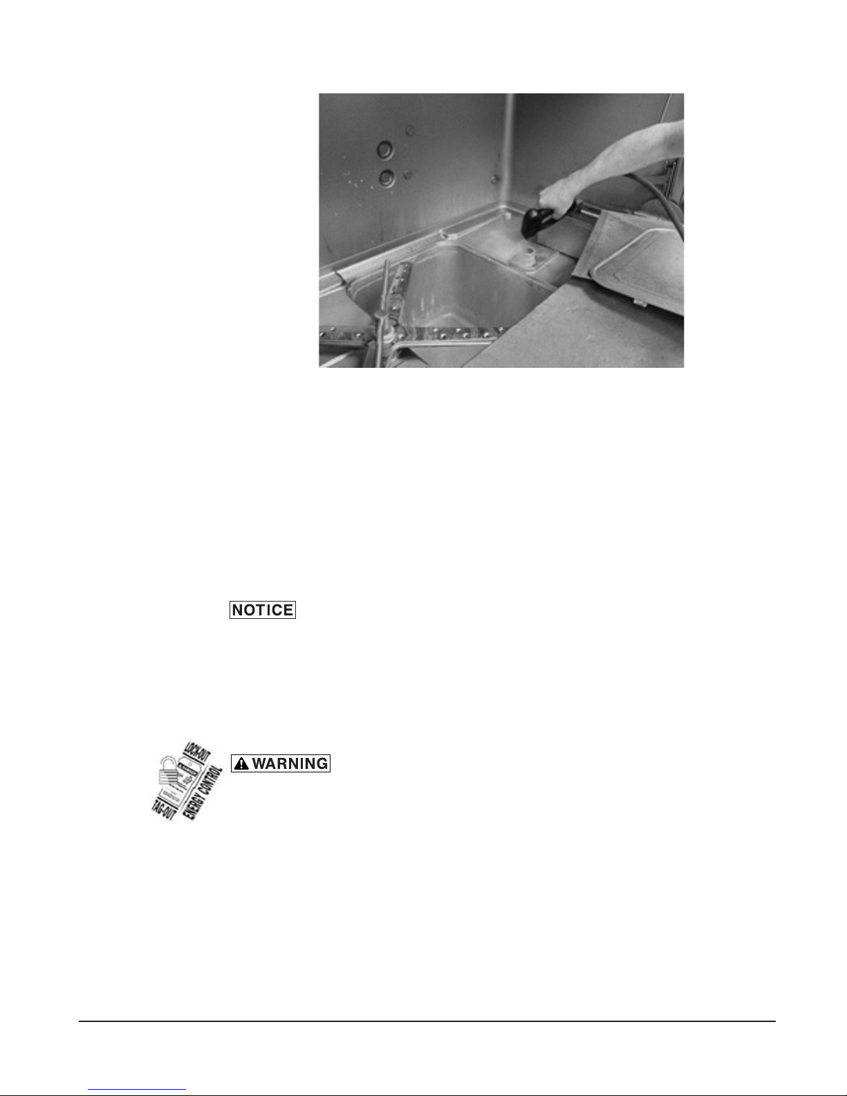
6. Spray down sump (Fig. 24).
Fig. 24
7. Turn machine back on for 2 minutes to ll.
8. Turn off machine again to ush sump.
9. With a damp cloth, wipe the interior and exterior of the machine. DO NOT use
steel wool. Remove any remaining debris with a mild cleanser formulated for
stainless steel and a soft cloth or brush.
10. Carefully reinstall the strainer pans and strainer basket.
11. Use a soft, damp cloth or sponge and mild cleanser to clean the control keypad
and display. DO NOT use abrasive or harsh cleaners or scouring pads.
12. Leave the doors open to allow the interior to dry and air out.
Do not use spray hose to spray down exterior of machine.
For Models PW10eR and PW20eR
In addition to normal cleaning, the bafes, located on the upper chamber on the
inside of the machine, may need periodic cleaning. Note that the PW20eR will
have two sets of bafes.
Disconnect the electrical power to the machine and follow
lockout / tagout procedures. There may be multiple circuits. Be sure all circuits
are disconnected.
1. Loosen and remove the nut from the front bafe(s) and remove bafe(s) by
sliding the tab out of the retainer.
– 30 –
Page 31

REMOVE THIS NUT
FRONT BAFFLE
Fig. 25 Fig. 26
2. Debris may collect on the top surface of bafes and should be washed in a sink
with mild detergent and rinsed.
3. Replace all removed parts.
4. Leave machine door open to allow interior to air out and dry.
DO'S AND DON'TS FOR YOUR NEW HOBART DISHWASHER
DO ensure proper water hardness of 3 grains or less per gallon. Total Dissolved Solids (TDS)
must be 50 ppm or greater. Chlorides must not exceed 50 ppm.
DO pre-scrap dishes thoroughly.
DO use only detergents recommended by your chemical professional.
DO, at the end of the day, complete a manual cleaning cycle as needed; thoroughly cleanse
the machine, rinse, and dry (leave doors open).
DO closely follow the machine's deliming schedule.
RETAINER
DO use only products formulated to be safe on stainless steel.
DO NOT use detergents formulated for residential dishwashers.
DO NOT allow food soil to accumulate on the tank bottom.
DO NOT exceed chemical manufacturer's recommended concentrations for detergent,
rinse aid or lime scale remover.
DO NOT use steel wool to clean ware or dishwasher surface.
DO NOT allow foreign objects to enter the unit, especially metallic contaminants.
NOTE: Failure to follow use, care, and maintenance instructions may void your Hobart dishwasher
warranty.
– 31 –
Page 32

MOTOR
The motor has permanently sealed bearings and requires no lubrication.
WASH AND RINSE ARMS
All wash arms and rinse arms should turn freely and continue turning for a few
seconds after being whirled by hand. To check, DISCONNECT ELECTRIC POWER
SUPPLY, rotate arms and remove any obstructions causing improper operation.
Refer to CLEANING THE PREP WASHER on pages 27-31.
If the strainer pans and strainer basket are not properly in place, obstructions
(such as food particles or toothpicks) may clog the wash arm nozzles.
DELIMING
rinse solution containing bleach. Mixing may cause hazardous gas to form.
This entire procedure must be followed step- by-step for safe and satisfactory
results.
The dishwasher should be delimed on a regular basis as required. How often
depends on the mineral content of the water. Deliming should be done when you
can see clear signs of lime deposits (a white chalky substance) on the inside walls,
on the wash and rinse arms and tank heater. Inspect the machine interior for lime
deposits. If deliming is necessary, a deliming agent (such as Lime-A-Way® or
LSR®) should be used for best results.
MAINTENANCE
Deliming solution must not come in contact with bleach or
All Prep washers are equipped with an automatic delime cycle reminder. It is
recommended that deliming be done when DELIME RECOMMENDED is lit.
PW10eR and PW20eR models are equipped with an internal delime pump which
will automatically pump the required amount of deliming agent into the unit. All
PW10eR/PR20eR models are equipped with an automatic deliming system. At
installation, a qualied Hobart Service technician or your chemical supplier must
adjust the total water hardness setting to properly set the delime intervals.
Remove the deliming agent bottle cap and put the black delivery tube in the
container. Be sure to push the delivery tub standpipe completely to the bottom
of the container. Check to make sure there are no obstructions or kinks in the
delivery tube.
– 32 –
Page 33

After the preprogrammed number of cycles has expired, the control will indicate
the delime request by displaying DELIME RECOMMENDED and will prompt
‘would you like to delime now?’. You must enter ‘Yes’ or ‘No’ to proceed with a
delime cycle or to continue with normal machine operation. If ‘No’ is selected,
the machine will continue to notify the operator at each start-up and power down
until the delime cycle is completed. To delime the unit.
1. Press the MENU/DOWN Arrow key until the ‘>’ symbol is shown to the left of
‘YES’ and press the ENT key.
2. Remove rack from the machine.
3. Remove strainers from the machine and clean. Replace strainers and rack
and close door.
4. On PW10er/PW20eR machines, ensure delimer chemical container is not
empty. Be sure to push the delivery tube standpipe completely to the bottom
of the container. Check to make sure there are no obstructions or kinks in the
delivery tube.
5. Press ENT key to enter the delime mode. The machine will drain and rell with
fresh water.
6. On PW10/PW20 machines, after the deliming agent has been added, close the
door. Press the ENT key to continue the cycle. The machine will enter the wash
mode for about 25 minutes, then will begin two rinse and drain operations. Total
time to complete the delime operation will be about 45 minutes. ON PW10eR/
PW20eR machines, the unit will automatically enter the wash mode for about
40 minutes, then will begin several rinse and drain operations after the ll cycle
is complete. Total time to complete the delime operation will be about 1 hour
40 minutes.
7. After deliming operation is completed, the machine will shut down.
8. Inspect the interior of the machine for lime deposits. If necessary, another delime
cycle can be initiated by entering Manager Programming Mode.
Do not allow deliming agent to remain in the machine longer than
recommended by the deliming agent manufacturer. After deliming, run the
machine through two 6-minute cycles with no utensils in order to rinse and
ush machine interior.
– 33 –
Page 34

TROUBLESHOOTING
SYMPTOM POSSIBLE CAUSE
Utensils spotted or not
clean
Overloaded rack. Low water level. Water conditions:
— Incorrect rinse water temperature. Refer to WATER SUPPLY
CONNECTION, page 15.
— Excessive water hardness may indicate that a water softener is
needed.
— Incorrect detergent type or concentration for water conditions.
— Incorrect rinse additive for water conditions. Inadequate rinse.
— Dirty line strainer causing reduced water ow. Turn off water supply.
Remove ll hose and check strainer. Withdraw and clean screen.
Reassemble.
— Excessive mineral deposits throughout wash and rinse system.
Deliming may be necessary.
Check water level in tank. The machine won't clean well if there isn't enough
water for the pump to maintain adequate wash pressure.
Loss of water pressure due to pump obstruction.
— DISCONNECT ELECTRIC POWER SUPPLY. Drain tank and check for
obstruction at the strainers, basket and pump intake.
Insufcient detergent dispensing.
— Check supply or detergent supplier.
Excessive mineral deposits throughout wash and rinse system.
— Deliming may be necessary.
— Excessive water hardness may indicate that a water softener is
needed.
Prep washer was not cleaned properly. Refer to CLEANING THE PREP
WASHER. pages 27-31.
Wash arm blocked with debris. Refer to WASH AND RINSE ARMS, page 32
Machine won't operate Fuse blown or circuit breaker tripped.
Check water level in tank.
Leaking valves Solenoid valves.
— Contact service.
— Check valve on spray hose
— Foreign material preventing proper valve operation. A critical period
is soon after installation when pipe compound or metal shavings may
No wash tank heat
No ll or slow ll
lodge at the valve seat.
The low water detector will shut off heat if water level is too low.
— Check water level.
• Fuse blown or circuit breaker tripped.
• Heater failure
• Overtemperature protector tripped
— Contact service.
Dirty line strainer causing reduced water ow.
— Turn off water supply. Disconnect ll hose and remove strainer. Clean
screen. Reassemble.
.
SERVICE
Contact your Hobart service ofce for any repairs or adjustments needed on this
equipment. Long-term service contracts are available on this and other Hobart
products.
– 34 –
Page 35

– 1 –
Page 36

© HOBART 2015
– 2 –
Page 37

TABLE DES MATIÈRES
GÉNÉRAL ....................................................................4
INSTALLATION ................................................................4
DÉBALLAGE ..................................................................5
Retirer la machine de la pallette ................................................6
Retirer la section de récupération d'énergie, au besoin ..............................6
CODES D'INSTALLATION ......................................................10
EMPLACEMENT ..............................................................10
RACCORDS DE PLOMBERIE ...................................................15
Exigences de la qualité d'eau .................................................15
Conduite d'alimentation ......................................................15
Racords de plomberie .......................................................17
Drain ....................................................................17
Exigences de ventilation (PW10 / PW20) ........................................17
Calculs du débit d'échappement ...............................................17
Taille et emplacement de la hotte à auvent .......................................18
Calculs du débit d'échappement ...............................................18
Installations du doseur de produits chimiques .....................................18
Doseur de détergent (factultatif, installé par d'autres fournisseurs) ....................19
Doseur d'agent de rinçage (facultatif, installé par d'autres fournisseurs) ................19
Doseur de détartrant (standard) sur les modèles Advansys seulement (PW10eR/ PW20eR) 19
Évent (PW10 / PW20) .......................................................19
Commande du ventilateur d'évacuation (Standard) ;
Ventilateur d'évacuation forcée (Facultatif) PW10 / PW20 .........................19
RACCORD(S) ÉLECTRIQUE(S) ..................................................19
Direction du(es) moteur(s) de la pompe .........................................20
BRANCHEMENTS DE L'ÉQUIPEMENT ............................................21
Commande du ventilateur d'échappement .......................................21
Doseur de détergent ........................................................21
Doseur d'agent de rinçage ....................................................21
UTILISATION .................................................................22
COMMANDES ................................................................22
Utiliser le lave-batterie PW ...................................................22
PROGRAMMATION ...........................................................23
Programmer le mode de gestion ...............................................23
Instructions de programmation ................................................26
Invites de commande du menu ................................................26
Mode d'emploi général ......................................................27
NETTOYAGE .................................................................27
Pour les Modèles PW10eR et PW20eR .........................................30
ENTRETIEN .................................................................32
GICLEURS DE LAVAGE ET DE RINÇAGE .......................................32
DÉTARTRAGE ............................................................32
DÉPANNAGE ................................................................34
– 3 –
Page 38

Installation, utilisation et entretien du
lave-batterie modèle PW10/PW20
CONSERVEZ CES INSTRUCTIONS
GÉNÉRAL
Le lave-batterie PW10 et PW20 vous permet de laver un grand volume de couverts
dans votre cuisine, pâtisserie ou supermarché. Le PW10/20 occupe un minimum
d'espace de plancher (inférieur à 48 po x 43 po quand les portes sont ouvertes) et
ne demande aucune table à vaisselle supplémentaire. La portion supérieure de la
porte s'ouvre en se glissant vers le haut, tandis que la portion inférieure s'abat vers
l'extérieur pour offrir un plateau égouttoir. Le panier égouttoir peut ensuite être tiré
vers l'extérieur pour un chargement et déchargement facile.
Le clavier de commande permet de choisir un cycle de 2-, 4- ou 6- minutes ; chaque
cycle de lavage est suivi d'un temps d'arrêt et d'un deuxième rinçage de 10 (PW10,
PW10eR, PW20) ou 12 (PW20eR) seconds. Les modèles Advansys comprennent
un délai de condensation de 1½ à 2½ minutes suivant le cycle rinçage. Les gicleurs
de lavage supérieurs et inférieurs fournissent un lavage complet. Les gicleurs de
rinçage supérieurs et inférieurs fournissent un rinçage assainissant à chaque n
de cycle.
DÉBALLAGE
Le PW10/20 n'est disponible qu'avec un chauffage électrique et équippé d'un
surchauffeur électrique. Un boyau avec pistolet d'arrosage est fourni sur le côté
de la machine.
Le système comprend : un système d'égouttage incliné, drainage à pompe, remplissage
automatique et plateau égouttoir avec cales pour insérer des paniers égouttoirs. Le
plateau peut accomoder le bol de 140 quarts (132.50L) du batteur Hobart.
INSTALLATION
Immédiatement après avoir déballé votre lave-batterie PW10/PW2, vériez qu'il n'a
pas subit d'endommagement lors de sa livraison. En cas de dommage, conservez le
matériel d'emballage et contactez le transporteur dans les 5 jours suivant la livraison.
Avant l'installation, vériez que votre branchement électrique se concorde avec
les spécications de la plaque signalétique située sur la partie inférieure droite de
la porte du haut.
– 4 –
Page 39

Retirer la machine de la palette
Retirez soigneusement la machine de la palette :
1. Enlevez les supports d'expédition de la machine/palette.
Fig. 1
2. Retirez les planches du dessous de la palette à l'aide d'un transpalette.
AVIS
Prendre soin et porter un équipement de protection lors de la manipulation
de planches avec des clous saillants.
Fig. 2 Fig. 3
3. Descendez les pieds en les dévissant.
4. La machine se supportant maintenant par ses pieds, sortez la palette en la
faisant passer par dessous de la machine.
REMARQUE : Sur la machine PW20, vous pourriez avoir à défaire les parties
latérales de la palette pour faciliter la tâche.
– 5 –
Page 40

Retirer la section de récupération d'énergie, au besoin
AVERTISSEMENT
Débranchez l'alimentation électrique à la machine et suivez
les étapes d'étiquetage / verrouillage. Il pourrait avoir plusieurs circuits.
Assurez-vous que tous les circuits sont débranchés.
REMARQUE : Les étapes suivantes démontrent le retrait d'une seule unité
de récupération d'énergie. Si vous retirez les deux unités du modèle PW20
Advansys, répétez les étapes 2 à 10 de chaque côté..
1. Débranchez le boyau d'arrivée d'eau.
Fig. 4
REMARQUE : Videz tout l'excédent d'eau dans le boyau.
2. Retirez les gicleurs de lavage supérieurs et inférieurs.
Fig. 5
3. Retirez les déecteurs. (Situés sous les gicleurs de lavage et de rinçage).
a. Retirez le boulon (1).
b. Faites glisser le déecteur vers le côté pour le déloger de son support (2)
du côté opposé du déecteur.
c. Retirez les quatre écrous (3) qui retiennent le système de récupération
d'énergie à l'intérieur de la zone de lavage.
– 6 –
Page 41

Fig. 6
2. Retirez la coiffe.
Fig. 7
3. Retirez le couvercle de l'assemblage de verrouillage de la porte.
Fig. 8
– 7 –
Page 42

4. Retirez le couvercle de la boîte à bornes.
Fig. 9
5. Étiquetez les câbles du moteur pour les reconnecter plus tard.
6. Débranchez les câbles du moteur.
Fig. 10
– 8 –
Page 43

7. Débranchez les boyaux raccordés à l'assemblage de récupération d'énergie.
Fig. 11
8. Retirez les boulons (Qté 13) autour de l'assemblage de récupération d'énergie.
Fig. 12 Fig. 13
– 9 –
Page 44

9. Soulevez l'assemblage de récupération d'énergie de la machine.
10. Inversez cette procédure pour réinstaller.
REMARQUE : Si vous avez retiré les unités de récupération d'énergie pour
accéder à l'ouverture d'une porte, lorsque vous les réinstallez, retirez le ruban
mousse, nettoyez la surface et installez un nouveau ruban sur la monture
pour assurer un joint étanche.
CODES D'INSTALLATION
L'installation doit se conformer aux codes provinciaux, locaux et le code national
électrique ANSI/NFPA70 (dernière édition). Au Canada, le code d'installation est
le CSA 22.1 (dernière édition).
EMPLACEMENT
Mettre la machine en place après que le dernier recouvrement de plancher est
installé. Assurez-vous que la machine est mise à niveau avant de faire les raccords
de plomberie. Laisser un dégagement d'au moins 3" à l'arrière et de 18" aux abords
de la machine pour permettre un accès de service. Laisser un dégagement d'au
moins 16" à l'avant de la machine pour permettre à la porte de s'ouvrir et un espace
supplémentaire pour permettre à l'utilisateur de travailler.
Fig. 14
– 10 –
Page 45

Les branchements électriques et de mise à la terre
doivent être conformes aux portions applicables du code
électrique national et/ou tout autre code électrique local.
Les raccords de plomberie doivent être conformes aux
codes sanitaires, de sécurité et de plomberies appli-
cables. Les configurations de drain et de conduit
d’alimentation peuvent varier. Quelques méthodes sont
affichées sur ce schéma.
AVERTISSEMENT
REMARQUES SUR LA PLOMBERIE :
La pression d'eau du bâtiment doit être de 15-65 PSIG. Si la pression excède 65 PSIG,
une vanne de régulation de pression doit être installée sur la conduite d'eau en direc-
tion de la machine (non incluse).
LA duretée de l’eau recommandée est de 3 grains ou moins pour obtenir les meilleurs
résultats.
Une jauge de pression d’eau n’est pas nécessaire sur les machines à rincage pompé.
REMARQUES DIVERS :
Prévention de retour effectuée par dispositif d’intervalle d’air approuvée par NSF.
Machines avec raccord à point unique.
Toutes les dimensions prises de la conduite du plancher pourrait augmenter de 1-1/2” selon l’ajustement des
pattes de la machine.
Poids net de la machine : 324 lb
Poids à l’expédition domestique : 387 lb
Dimensions d’expédition :
79-1/8” H X 40-1/4”L X 40”l
Taille des paniers:
23-3/4” X 26-5/8” X 2-1/4”
DÉGAGEMENT MINIMUM
SUGGÉRÉ POUR ACCÈS DE SERVICE
DES DEUX CÔTÉS.
DÉGAGEMENT
REQUIS POUR LE
PISTOLET
D’ARROSAGE
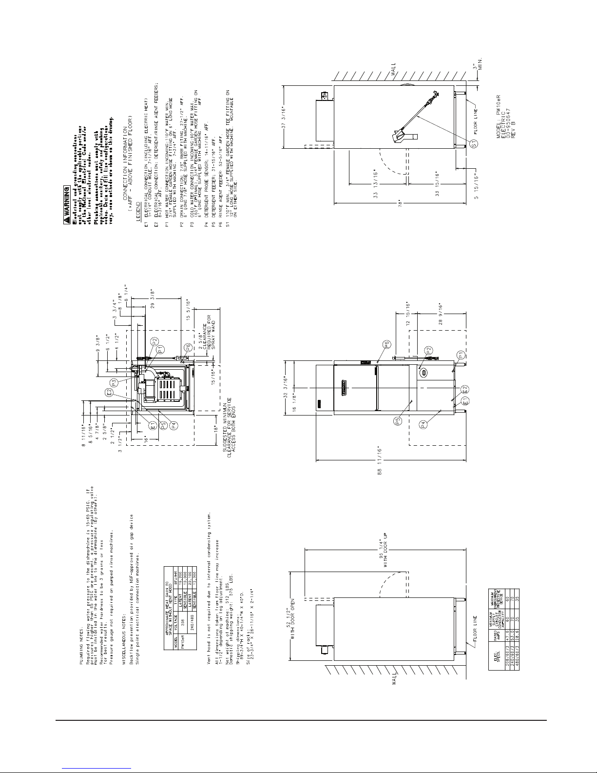
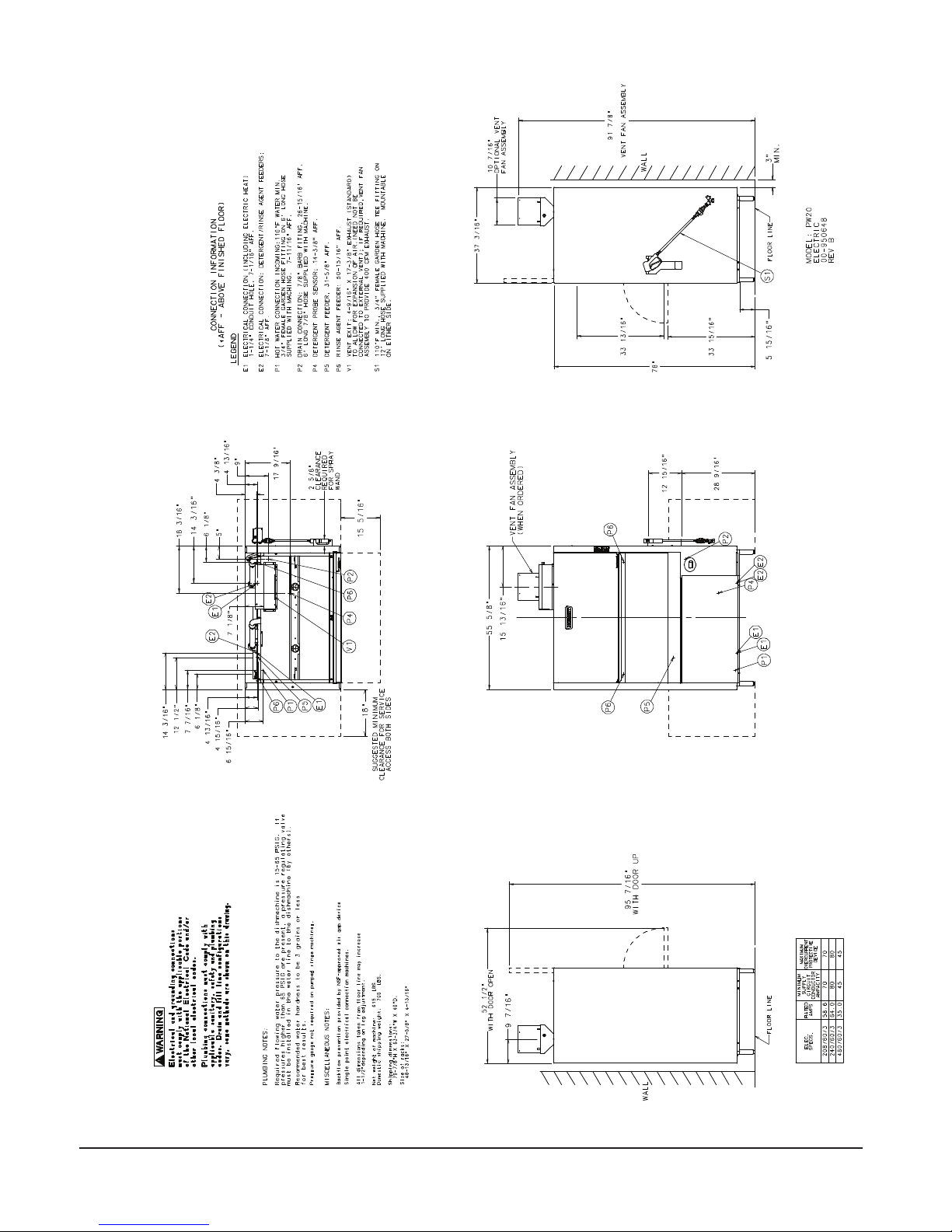
INFORMATION SUR LES RACCORDS
(*AFF - AU DESSUS DU NIVEAU DÉFINITIF DU SOL)
LÉGENDE
E1 RACCORD ÉLECTRIQUE (Y COMPRIS LA CHALEUR ÉLECTIQUE)
1-1/4” DIAMÈTRE DE CONDUIT, 7-1/16“ AFF.
E2 RACCORD ÉLECTRIQUE : DOSEURS DE DÉTERGENT/AGENT DE RINÇAGE ;
8-3/16” AFF.
P1 RACCORD DE L’EAU CHAUDE ENTRANTE : 110’F MINIMUM.
RACCORD FEMELLE DE BOYAU D’ARROSAGE DE 3/4“ SUR BOYAU DE 6’
INCLUS AVEC LA MACHINE. 7-3/4” AFF.
P2 RACCORD DU DRAIN : RACCORD DE SCELLEMENT À CRAN DE 7/8“, 27-3/8” AFF.
BOYAU DE 7/8“ ET 6‘ DE LONG INCLUS AVEC LA MACHINE.
P4 SONDE DU NIVEAU DE DÉTERGENT ; 14-11/16” AFF.
P5 DOSEUR DE DÉTERGENT : 31-15/16“ AFF.
P6 DOSEUR D’AGENT DE RINÇAGE : 52-5/16” AFF.
V1 ÉVENT : 4-9/16“ X 17-3/8” (STANDARD) POUR PERMETTRE L’EXPANSION DE L’AIR.
(PAS BESOIN DE RACCORDER À UN ÉVENT EXTÉRIEUR) ; AU BESOIN, ASSEMBLAGE DE
VENTILATEUR D’ÉCHAPPEMENT POUR OFFRIR UNE VENTILATION DE 400 CFM.
S1 110’F MIN., RACCORD EN T FEMELLE DE BOYAU D’ARROSAGE DE 3/4“ SUR BOYAU
DE 12’ INCLUS AVEC LA MACHINE. PEUT ÊTRE INSTALLÉ SUR LES DEUX CÔTÉS.
AVEC PORTE OUVERTE
AVEC PORTE VERS LE HAUT
LIGNE DU PLANCHER
ASSEMBLAGE DU VENTILATEUR D’ÉCHAPPPEMENT
(LORSQUE COMMANDÉ)
LIGNE DU
PLANCHER
ASSEMBLAGE DU VENTILATEUR
D’ÉCHAPPPEMENT FACULTATIF
ASSEMBLAGE DU VENTILATEUR
D’ÉCHAPPPEMENT FACULTATIF
MODÈLE : PW10
ÉLECTRIQUE
00-95-0647
RÉV B.
SPÉC.
ÉLEC.
TENSION
NOMINALE
EN AMPÈRES
INTENSITÉ ADMISSIBLE
MINIMUM DU CIRCUIT
D’ALIMENTATION
DISPOSITIF DE
PROTECTION DE
SURINTENSITÉ MAXIMUM
208/60/3 47.6 60 60
240/60/3 53.0 70 70
480/60/3 28.6 35 35
PW10
– 11 –
Page 46

INFORMATION SUR LES RACCORDS
240/60/3
53.0
70
70
480/60/3
28.6
35
35
À LA PIÈCE SANS HOTTE À AUVENT
(*AFF - AU DESSUS DU NIVEAU DÉFINITIF DU SOL)
AVERTISSEMENT
Les branchements électriques et de mise à la terre
doivent être conformes aux portions applicables du code
électrique national et/ou tout autre code électrique local.
Les raccords de plomberie doivent être conformes aux
codes sanitaires, de sécurité et de plomberies appli-
cables. Les configurations de drain et de conduit
d’alimentation peuvent varier. Quelques méthodes sont
affichées sur ce schéma.
E1 RACCORD ÉLECTRIQUE (Y COMPRIS LA CHALEUR ÉLECTIQUE)
LÉGENDE
1-1/4” DIAMÈTRE DE CONDUIT, 7-1/16“ AFF.
E2 RACCORD ÉLECTRIQUE : DOSEURS DE DÉTERGENT/AGENT DE RINÇAGE ;
8-3/16” AFF.
P1 RACCORD DE L’EAU CHAUDE ENTRANTE : 110’F MINIMUM.
RACCORD FEMELLE DE BOYAU D’ARROSAGE DE 3/4“ SUR BOYAU DE 6’
INCLUS AVEC LA MACHINE. 7-3/4” AFF.
P3 RACCORD DE L’EAU FROIDE ENTRANTE : 90’F MAXIMUM.
(65’F OPTIMAL) RACCORD FEMELLE DE BOYAU D’ARROSAGE DE 3/4“ SUR BOYAU DE 6’
INCLUS AVEC LA MACHINE. 76-7/16” AFF.
P2 RACCORD DU DRAIN : RACCORD DE SCELLEMENT À CRAN DE 7/8“, 27-1/2” AFF.
BOYAU DE 7/8“ ET 6‘ DE LONG INCLUS AVEC LA MACHINE.
P4 SONDE DU NIVEAU DE DÉTERGENT ; 14-11/16” AFF.
P5 DOSEUR DE DÉTERGENT : 31-15/16“ AFF.
P6 DOSEUR D’AGENT DE RINÇAGE : 52-5/16” AFF.
S1 110’F MIN., RACCORD EN T FEMELLE DE BOYAU D’ARROSAGE DE 3/4“ SUR BOYAU
DE 12’ INCLUS AVEC LA MACHINE. PEUT ÊTRE INSTALLÉ SUR LES DEUX CÔTÉS.
DÉGAGEMENT
REQUIS POUR LE
PISTOLET
D’ARROSAGE
LIGNE DU
PLANCHER
MODÈLE : PW10eR
ÉLECTRIQUE
00-950647
RÉV B.
LATENT 20 100
LATENT 16 200
SENSIBLE 10 000
SENSIBLE 12 300
208
240/480
APPORT DE CHALEUR APPROXIMATIF
PW10eR
MODÈLE VOLTAGE TYPE BTU/HR
REMARQUES DIVERS :
Prévention de retour effectuée par dispositif d’intervalle d’air approuvée par NSF.
REMARQUES SUR LA PLOMBERIE :
La pression d'eau du bâtiment doit être de 15-65 PSIG. Si la pression excède 65 PSIG,
une vanne de régulation de pression doit être installée sur la conduite d'eau en direc-
tion de la machine (non incluse).
LA duretée de l’eau recommandée est de 3 grains ou moins pour obtenir les meilleurs
résultats.
Machines avec raccord à point unique.
Une jauge de pression d’eau n’est pas nécessaire sur les machines à rincage pompé.
Hotte à auvent non requise grâce au système de consensation interne.
Toutes les dimensions prises de la conduite du plancher pourrait augmenter de 1-1/2”
DES DEUX CÔTÉS.
DÉGAGEMENT MINIMUM
SUGGÉRÉ POUR ACCÈS DE SERVICE
AVEC PORTE OUVERTE
selon l’ajustement des pattes de la machine.
Poids net de la machine : 512 lb
Poids à l’expédition domestique : 575 lb
Dimensions d’expédition :
39-3/4” H X 40-1/4”L X 40”l
Taille des paniers:
23-3/4” X 26-11/16” X 2-1/4”
PW10eR
AVEC PORTE VERS LE HAUT
MUR
DISPOSITIF DE
PROTECTION DE
SURINTENSITÉ MAXIMUM
D’ALIMENTATION
INTENSITÉ ADMISSIBLE
MINIMUM DU CIRCUIT
TENSION
NOMINALE
EN AMPÈRES
LIGNE DU PLANCHER
ÉLEC.
SPÉC.
208/60/3 47.6 60 60
– 12 –
Page 47

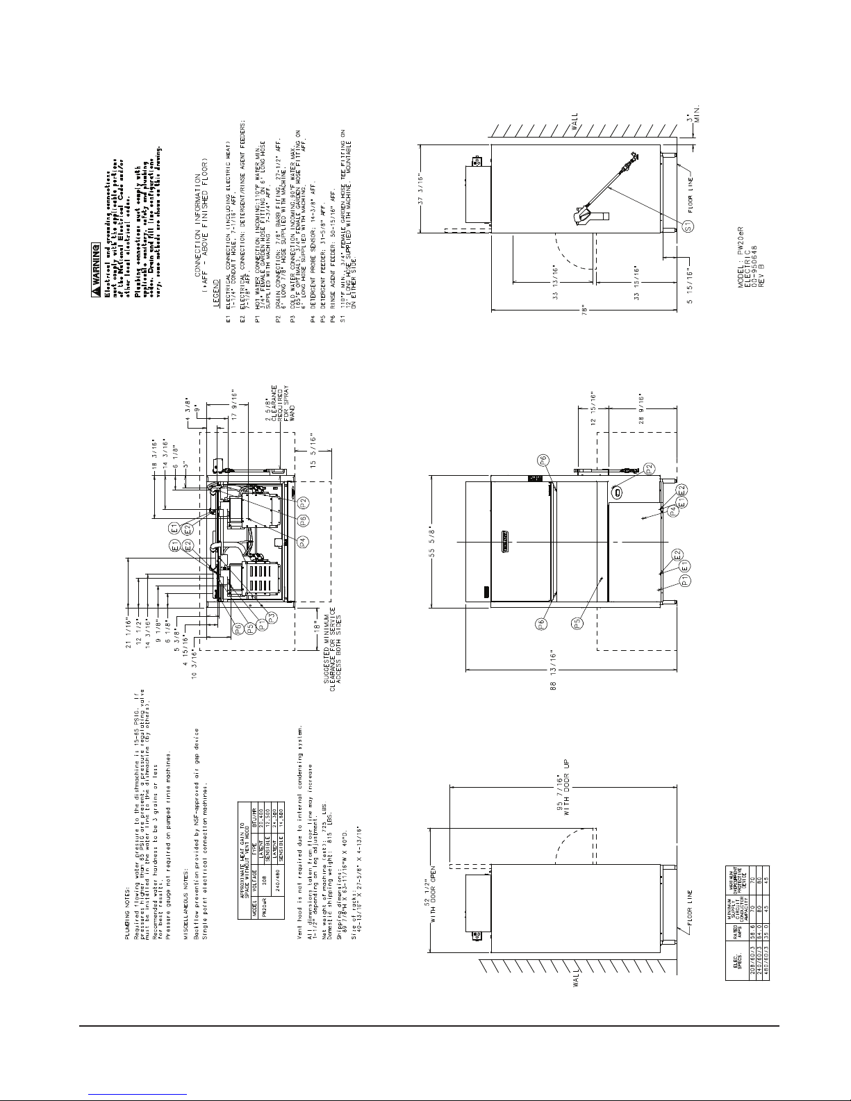
INFORMATION SUR LES RACCORDS
(*AFF - AU DESSUS DU NIVEAU DÉFINITIF DU SOL)
E1 RACCORD ÉLECTRIQUE (Y COMPRIS LA CHALEUR ÉLECTIQUE)
1-1/4” DIAMÈTRE DE CONDUIT, 7-1/16“ AFF.
E2 RACCORD ÉLECTRIQUE : DOSEURS DE DÉTERGENT/AGENT DE RINÇAGE ;
7-1/8” AFF.
P1 RACCORD DE L’EAU CHAUDE ENTRANTE : 110’F MINIMUM.
RACCORD FEMELLE DE BOYAU D’ARROSAGE DE 3/4“ SUR BOYAU DE 6’
INCLUS AVEC LA MACHINE. 7-11/16” AFF.
P2 RACCORD DU DRAIN : RACCORD DE SCELLEMENT À CRAN DE 7/8“, 26-15/16” AFF.
BOYAU DE 7/8“ ET 6‘ DE LONG INCLUS AVEC LA MACHINE.
P4 SONDE DU NIVEAU DE DÉTERGENT ; 14-3/8” AFF.
P5 DOSEUR DE DÉTERGENT : 31-5/8“ AFF.
P6 DOSEUR D’AGENT DE RINÇAGE : 50-5/16” AFF.
LÉGENDE
V1 ÉVENT : 4-9/16“ X 17-3/8” (STANDARD) POUR PERMETTRE L’EXPANSION DE L’AIR.
DÉGAGEMENT
REQUIS POUR LE
PISTOLET
D’ARROSAGE
ASSEMBLAGE DU VENTILATEUR
D’ÉCHAPPPEMENT FACULTATIF
(PAS BESOIN DE RACCORDER À UN ÉVENT EXTÉRIEUR) ; AU BESOIN, ASSEMBLAGE DE
VENTILATEUR D’ÉCHAPPEMENT POUR OFFRIR UNE VENTILATION DE 400 CFM.
S1 110’F MIN., RACCORD EN T FEMELLE DE BOYAU D’ARROSAGE DE 3/4“ SUR BOYAU
DE 12’ INCLUS AVEC LA MACHINE. PEUT ÊTRE INSTALLÉ SUR LES DEUX CÔTÉS.
ASSEMBLAGE DU VENTILATEUR D’ÉCHAPPPEMENT
(LORSQUE COMMANDÉ)
ASSEMBLAGE DU VENTILATEUR
D’ÉCHAPPPEMENT FACULTATIF
LIGNE DU
PLANCHER
MODÈLE : PW20
ÉLECTRIQUE
00-950648
RÉV B.
AVERTISSEMENT
Les branchements électriques et de mise à la terre
doivent être conformes aux portions applicables du code
électrique national et/ou tout autre code électrique local.
REMARQUES SUR LA PLOMBERIE :
La pression d'eau du bâtiment doit être de 15-65 PSIG. Si la pression excède 65 PSIG,
une vanne de régulation de pression doit être installée sur la conduite d'eau en direc-
tion de la machine (non incluse).
LA duretée de l’eau recommandée est de 3 grains ou moins pour obtenir les meilleurs
Les raccords de plomberie doivent être conformes aux
codes sanitaires, de sécurité et de plomberies appli-
cables. Les configurations de drain et de conduit
d’alimentation peuvent varier. Quelques méthodes sont
affichées sur ce schéma.
résultats.
SUGGÉRÉ POUR ACCÈS
DÉGAGEMENT MINIMUM
DE SERVICE DES DEUX CÔTÉS.
AVEC PORTE OUVERTE
Une jauge de pression d’eau n’est pas nécessaire sur les machines à rincage pompé.
REMARQUES DIVERS :
Prévention de retour effectuée par dispositif d’intervalle d’air approuvée par NSF.
Machines avec raccord à point unique.
Toutes les dimensions prises de la conduite du plancher pourrait augmenter de 1-1/2”
selon l’ajustement des pattes de la machine.
Poids net de la machine : 615 lb
Poids à l’expédition domestique : 705 lb
Dimensions d’expédition :
79-7/8” H X 63-3/4”L X 40”l
Taille des paniers:
48-13/16” X 27-5/8” X 4-13/16”
PW20
– 13 –
AVEC PORTE VERS LE HAUT
MUR
DISPOSITIF DE
PROTECTION DE
SURINTENSITÉ MAXIMUM
D’ALIMENTATION
INTENSITÉ ADMISSIBLE
MINIMUM DU CIRCUIT
TENSION
NOMINALE
LIGNE DU PLANCHER
EN AMPÈRES
ÉLEC.
SPÉC.
208/60/3 58.6 70 70
240/60/3 64.0 80 80
480/60/3 35.0 45 45
Page 48

INFORMATION SUR LES RACCORDS
EN AMPÈRES
D’ALIMENTATION
SURINTENSITÉ MAXIMUM
(*AFF - AU DESSUS DU NIVEAU DÉFINITIF DU SOL)
AVERTISSEMENT
Les branchements électriques et de mise à la terre
doivent être conformes aux portions applicables du code
électrique national et/ou tout autre code électrique local.
Les raccords de plomberie doivent être conformes aux
codes sanitaires, de sécurité et de plomberies appli-
cables. Les configurations de drain et de conduit
d’alimentation peuvent varier. Quelques méthodes sont
affichées sur ce schéma.
E1 RACCORD ÉLECTRIQUE (Y COMPRIS LA CHALEUR ÉLECTIQUE)
LÉGENDE
1-1/4” DIAMÈTRE DE CONDUIT, 7-1/16“ AFF.
E2 RACCORD ÉLECTRIQUE : DOSEURS DE DÉTERGENT/AGENT DE RINÇAGE ;
7-1/8” AFF.
P1 RACCORD DE L’EAU CHAUDE ENTRANTE : 110’F MINIMUM.
RACCORD FEMELLE DE BOYAU D’ARROSAGE DE 3/4“ SUR BOYAU DE 6’
INCLUS AVEC LA MACHINE. 7-3/4” AFF.
P2 RACCORD DU DRAIN : RACCORD DE SCELLEMENT À CRAN DE 7/8“, 27-1/2” AFF.
BOYAU DE 7/8“ ET 6‘ DE LONG INCLUS AVEC LA MACHINE.
P4 SONDE DU NIVEAU DE DÉTERGENT ; 14-3/8” AFF.
P5 DOSEUR DE DÉTERGENT : 31-5/8“ AFF.
P6 DOSEUR D’AGENT DE RINÇAGE : 52-5/16” AFF.
S1 110’F MIN., RACCORD EN T FEMELLE DE BOYAU D’ARROSAGE DE 3/4“ SUR BOYAU
DE 12’ INCLUS AVEC LA MACHINE. PEUT ÊTRE INSTALLÉ SUR LES DEUX CÔTÉS.
DÉGAGEMENT
REQUIS POUR LE
PISTOLET
D’ARROSAGE
P3 RACCORD DE L’EAU FROIDE ENTRANTE : 90’F MAXIMUM.
(65’F OPTIMAL) RACCORD FEMELLE DE BOYAU D’ARROSAGE DE 3/4“ SUR BOYAU DE 6’
INCLUS AVEC LA MACHINE. 76-5/8” AFF.
LIGNE DU
PLANCHER
MODÈLE : PW20eR
ÉLECTRIQUE
00-950648
RÉV B.
DÉGAGEMENT MINIMUM
LATENT 24 300
LATENT 20 400
SENSIBLE 12 500
SENSIBLE 14 800
208
240/480
À LA PIÈCE SANS HOTTE À AUVENT
APPORT DE CHALEUR APPROXIMATIF
PW10eR
MODÈLE VOLTAGE TYPE BTU/HR
REMARQUES DIVERS :
Prévention de retour effectuée par dispositif d’intervalle d’air approuvée par NSF.
REMARQUES SUR LA PLOMBERIE :
La pression d'eau du bâtiment doit être de 15-65 PSIG. Si la pression excède 65 PSIG,
une vanne de régulation de pression doit être installée sur la conduite d'eau en direc
tion de la machine (non incluse).
LA duretée de l’eau recommandée est de 3 grains ou moins pour obtenir les meilleurs
résultats.
Machines avec raccord à point unique.
Une jauge de pression d’eau n’est pas nécessaire sur les machines à rincage pompé.
Hotte à auvent non requise grâce au système de consensation interne.
Toutes les dimensions prises de la conduite du plancher pourrait augmenter de 1-1/2”
DES DEUX CÔTÉS.
SUGGÉRÉ POUR ACCÈS DE SERVICE
AVEC PORTE OUVERTE
selon l’ajustement des pattes de la machine.
Poids net de la machine : 725 lb
Poids à l’expédition domestique : 815 lb
Dimensions d’expédition :
89-7/8” H X 63-11/16”L X 40”l
Taille des paniers:
40-13/16” X 27-5/8” X 4-13/16”
PW20eR
– 14 –
AVEC PORTE VERS LE HAUT
MUR
DISPOSITIF DE
PROTECTION DE
INTENSITÉ ADMISSIBLE
MINIMUM DU CIRCUIT
TENSION
LIGNE DU PLANCHER
NOMINALE
ÉLEC.
SPÉC.
208/60/3 58.6 70 70
240/60/3 64.0 80 80
480/60/3 35.0 45 45
Page 49

RACCORD(S) DE PLOMBERIE
AVERTISSEMENT
conformes avec les portions applicables du code électrique national (NFPA No.
70, CSA 22.1 dernière édition) et/ou autres codes électriques locaux.
Exigences de la qualité d'eau
Une bonne qualité de l'eau peut améliorer la performance du lavage des couverts
en réduisant les taches d'eau, l'efcacité de la main-d'oeuvre et la durée de vie de
l'équipement. Les conditions de l'eau peuvent varier d'un endroit à l'autre. Le traitement
de l'eau recommandé pour l'utilisation efcace et productive de cet équipement dépend
aussi des conditions locales de l'eau. Demandez à votre spécialiste en eau municipal
au sujet des conditions locales de l'eau avant l'installation.
La duretée de l'eau recommandé est de 3 grains par gallon (42.7mg/l) et moins. Une
dureté supérieure à 3 grains par gallon demande un traitement de l'eau. Le traitement
de l'eau réduit les coûts associés au nettoyage, le nombre de détartrage requis et la
quantité de détergent nécessaire. La teneur en chlorure ne doit pas excéder 50 ppm.
Les raccords électriques et de mise à la terre doivent être
AVIS
Une teneur élevée en fer dans l'eau peut causer des taches et demander
un ltre à fer. Une teneur élevée en chlorures dans l'eau pourrait causer des
piqûres de corrosion et demander l'installation d'un système d'élimination de
chlore. Contactez votre spécialiste en eau local pour des solutions de traitement
de l'eau.
La présence de sédiments dans l'eau pourraient demander l'installation d'un ltre à
particules. La présence de solides dissous pourrait rendre nécessaire l'installation d'un
système de traitement comme un adoussisseur ou un système d'osmose inversée,
etc. Contactez votre spécialiste de traitement de l'eau local pour des solutions de
traitement de l'eau.
Si une inspection du lave-vaisselle ou du surchauffeur révèle une accumulation
de calcaire après un certain temps d'opération, il est recommandé d'installer un
système de traitement de l'eau. Si un adoussisseur est déjà installé, vériez que
le niveau de sel est sufsant. Contactez le bureau de service à la clientèle Hobart
pour des recommandations plus spéciques.
Conduite d'alimentation
La conduite d'alimentation devrait être un boyeau mâle de ¾ po (non-incluse).
Le plombier installateur de cette machine doit s'assurer que les conduites d'eau sont
COMPLÈTEMENT RINÇÉS AVANT de les raccorder au lave-batterie. Ce rinçage est
nécessaire pour éliminer tous les corps étrangers, comme des copeaux de métal
(provenant de la coupe ou du letage des tuyaux), de la pâtes à joint ; ou dans le
cas des raccords de tuyauterie soudus, des particules de soudures ou des retailles
suite à leur coupe. Si ces débris ne sont pas éliminés, ils peuvent se loger dans les
composantes de tuyauterie du lave vaisselle et les rendre défectueuses. L'obstruction
des vannes manuelles ou solénoides par des corps étrangers et tous les frais relatifs
à cette obstruction ne relève PAS de la responsabilité du fabricant et tous les coûts
associés à la réparation ne sont pas couverts par la garantie.
– 15 –
Page 50

Exigences en approvisionnement en eau :
EXIGENCES EN APPROVISIONNEMENT EN EAU
Modèle Approvisionnement Température
PW10 Eau chaude 110°F (43°C) Minimum
PW10eR Eau froide 55°F (13°C) Minimum, 80°F (27°C) Maximum
Eau chaude 110°F (43°C) Minimum
PW20 Eau chaude 110°F (43°C) Minimum
PW20eR Eau froide 55°F (13°C) Minimum, 80°F (27°C) Maximum
Eau chaude 110°F (43°C) Minimum
Les modèles PW10eR et PW20eR demandent des raccords en eau chaude et froide.
AVIS
Sur les installations PW10eR et PW20eR, l'eau froide entrante ne doit
pas excéder 80°F (27°C) pour fonctionner correctement. Pour un résultat
optimal, il pourrait être nécessaire d'utiliser un boyau de ½” pour l'eau froide
et minimiser la distance entre le lave-batterie et son entrée dans le bâtiment.
L'isolation de la tuyauterie peut aussi offrir de meilleurs résultats.
Si la température de l'eau froide s'élève au dessus de 80°F (27°C) de manière
constante ou si une quantité excessive de vapeur d'eau s'échappe dans la pièce
après que le cycle de condensation soit terminé, contactez le service à la clientèle
de Hobart an d'allonger le délai de condensation.
La pression d'eau du bâtiment doit être de 15-65 PSIG. Si la pression excède 65
PSIG, une vanne de régulation de pression doit être installée sur la conduite d'eau
en direction de la machine (non incluse). Si la pression d'eau est inférieure à 15
psi, ceci pourrait causer un fonctionnement inadéquat. Tous les modèles PW sont
dotés d'un système de rinçage à pompe ; donc, une jauge de pression d'eau n'est
pas nécessaire et n'est pas incluse avec la machine.
AVIS
Le régulateur de pression d'eau doit être doté d'une soupape de
pression différentielle. Ne pas utiliser le bon régulateur de pression pourrait
endommager l'unité.
Un robinet de sectionnement (non inclus) devrait être installé en amont du boyau
de remplissage pour permettre l'entretien de la machine.
Il est recommandé d'installer un ltre de conduite d'eau (non inclus) sur la conduite
d'alimentation entre le robinet de sectionnement et le point de raccord de la machine.
Installez les raccords de plomberie avec une tuyauterie de cuivre au diamètre extérieur
de ½” minimum (¾” recommandé), avec un raccord mâle de boyau d'arrosage de
¾” (non inclus). Voir les diagrammes d'installation aux pages 11-14.
– 16 –
Page 51

Raccords de plomberie
AVERTISSEMENT
Les raccords de plomberies doivent être conformes aux codes
sanitaires, de sécurité et de plomberie.
Drain
Un tuyau de drain au diamètre intérieur de ⅞" et d'une longueur de 6' est inclus.
Celui-ci devrait être bien raccordé dans un drain. Faire attention de ne pas couder le
tuyau. Voir les diagrammes d'installation aux pages 11-14. Le pouvoir d'écoulement
du drain doit être d'un minimum de 18 gallons par minutes (68 l/min) pour les modèles
PW10/PW10eR et 26 gallons par minute (98 l/min) pour les modèles PW20/PW20eR.
Exigences de ventilation (PW10 / PW20)
Les hottes à auvent de type I ou II sont recommandés. Les hottes doivent être
installés selon les instructions du fabricant. Un appoint d'air doit être fourni pour
que le débis d'échappement d'air résulte à une pression négative dans la pièce où
l'unité est située (plus d'échappement d'air que d'air à l'extérieur). Les hottes qui ne
sont pas fabriqués en usine, testés selon la norme UL 710 et les fabrications hors-
série doivent se conformer aux spécications suivantes : Acier inoxydable d'une
épaisseur de 0,037 po (0,94 mm) [calibre 20] ou feuilles de cuivre d'au moins 24
onces par pied carré (7 Kg/m2) ; la hotte devrait être xée en place par des supports
ininammables et doit se conformer au CALCULS du DÉBIT D'ÉCHAPPEMENT
à la page suivante.
AVIS
Assurez-vous que l'installation se conforme aux codes du bâtiment
locaux.
Calculs du débit d'échappement (FIG. 14)
Selon le code mécanique international de 2015.
– 17 –
Fig. 15
Page 52

Taille et emplacement de la hotte à auvent
Le rebord inférieur à l'intérieur des hottes à auvent commerciales de type I et II
doit surplomber ou s'étendre d'une distance horizontale d'au moins 6 po (162 mm)
au delà des coins du sommet horizontal de l'appareil dans toutes les directions
dégagées. La distance verticale entre le rebord inférieur à l'extérieur de la hotte et
la surface de l'appareil ne doit pas excéder 4 pieds (1219 mm) ou être inférieur à
1 pied (305 mm).
Surplomb de l'ouverture avant d'un minimum de 18 po.
Le DÉBIT d'air requis pour une hotte à auvent est d'un minimum de 100 CFM par
pied linéaire de longueur de la hotte.
Calculs du débit d'air d'échappement
Selon le code mécanique international de 2015.
Le débit d'air pour les hottes de type II aux fonctions de lave-vaisselle doit être de
100 cfm par pied linéaire de longueur de la hotte. La quantité nette d'échappement
d'air doit être calculée en soustrayant le courant d'air envoyé directement dans une
cavité de hotte du débit d'échappement total d'une hotte.
Les modèles PW10eR et PW20eR n'exigent pas une hotte de type II. Selon l'article
507.3 du IMC 2015, les hottes de type II ne sont pas requises lorsque les charges
de chaleur et d'humidité sont incorporés dans la conception du système CVAC. Voir
tableur A pour les valeurs de dissipation de chaleur ou d'accumulation de chaleur
à la pièce.
Table A
DISSIPATION DE CHALEUR
Modèle Voltage
PW10 208V 13,600 6,000
PW10 240V / 480V 16,800 7,300
PW10eR 208V 16,200 10,000
PW10eR 240V / 480V 20,100 12,300
PW20 208V 17,100 7,500
PW20 240V / 480V 20,400 8,900
PW20eR 208V 20,400 12,500
PW20eR 240V / 480V 24,300 14,800
Chaleur latente
(BTU/HR)
Installations du distributeur de produit chimique
Cette machine doit être utilisée avec un doseur de produits chimiques, avec un
témoin visuel de vérier que les détergents sont injectés ou une alarme visuelle ou
audible pour signaler un problème d'injection des détergents au système de lavage.
Les doseurs de produits chimiques ne sont pas inclus. Pour les branchements
électriques, veuillez vous référer à la section Raccords De L’Equipment, page 21.
Chaleur sensible
(BTU/HR)
– 18 –
Page 53

Doseur de détergent (facultatif, non inclus)
Si installation d'un doseur de détergent (non-inclus), retirez le bouchon pour exposer
le trou de 7/8" de diamètre à l'arrière de la machine.
Agent de rinçage (facultatif, non inclus)
Si installion d'un doseur d'agent de rinçage (non-inlcus), retirez le(s) bouchon(s)
leté(s) de 1/8" NPT pour accéder au trou tarraudé dans la jonction en T sur le côté
droit de la machine (PW10/PW10eR) et à l'arrière de la machine (PW20/PW20eR).
Les machines PW20/PR20eR sont dotés de deux jonctions en T de rinçage.
Doseur de détartrant (standard) pour les modèles Advansys seulement (PW10eR/ PW20eR)
Un doseur de détartrant avec tubes et une conduite verticale est inclus, pour injecter
une solution de détartrant automatiquement lorsque nécessaire.
Évent (PW10 / PW20)
Un évent (4-9/16 " x 17-3/8") est installé au sommet de l'appareil pour permettre
l'expansion de l'air. Il ne doit pas être raccordé directement à une ventilation externe.
Commande du ventilateur d'évacuation (Standard); Ventilateur d'évacuation forcée
(faculatif) PW10/PW20
Le circuit de commande du ventilateur d'évacuation permet d'activer un ventilateur
d'évacuation (non-inclus). La hotte à auvent s'allume lorsque le PW10/20 est activé
et s'étteint lorsque le PW10/20 s'éteint. Le ventilateur d'évacuation forcée évacue
l'air humide une fois le cycle de rinçage terminé. Le ventilateur d'évacuation forcée
peut être réglé à 40, 60 ou 80 secondes. L'ensemble du ventilateur d'évacuation
forcée (installé sur place seulement) dépasse la machine verticalement de 12 ¼”
au dessus de la sortie d'air (13 5/16” au dessus de la chambre de lavage) et se
termine avec un raccord de conduit rond qui s'adapte à un conduit au diamètre
extérieur de 10 1/4".
Installez l'ensemble du ventilateur d'évacuation forcée à l'aide d'un maximum de
60 pieds de conduit de 10" de diamètre ; ou, 50 pieds de longueur avec deux (2)
coudes de 90°, ou l'équivalent. Les distances supérieures aux mesures maximales
ci-dessus pourraient réduire l'efcacité du ventilateur.
RACCORD(S) ÉLECTRIQUE(S)
AVERTISSEMENT
conformes avec toutes les sections applicables du code électrique national
(NFPA No. 70, dernière édition) et/ou tout autre codes électrique locaux.
Les raccords électriques et de mise à la terre doivent être
AVERTISSEMENT
les étapes d'étiquetage / verrouillage. Il pourrait avoir plusieurs circuits.
Assurez-vous que tous les circuits sont débranchés.
Débranchez l'alimentation électrique à la machine et suivez
– 19 –
Page 54

Raccordez le circuit d'arrivée au panneau de commande selon le diagramme situé
à l'arrière du panneau de garniture avant.
INFORMATIONS ÉLECTRIQUES
PW10 / PW10eR (Raccord à point unique)
Volts/Hz/ph Intensité nominale
en ampères
208/240/60/3 47,6 / 53,0 60 / 70
480/60/3 28,6 35
PW20 / PW20eR (Raccord à point unique)
Volts/Hz/ph Intensité nominale
en ampères
208/240/60/3 58.6 / 64.0 70 / 80
480/60/3 35,0 45
* Taille du circuit minimum / Dispositif de protection maximum (Ampères) compilés selon le code de électrique
national (NFPA 70), dernière édition.
** Pour le raccord d'arrivée, utilisez des câbles spéciés pour au moins 90°F (32,2°C) ou l'équivalent.
Révolution du(es) moteur(s) de la pompe
Avant d'utiliser la machine, vériez que le du moteur de la pompe tourne dans la
bonne direction.
Taille du circuit* en ampères
Taille du circuit* en ampères
PW10 / PW10eR
À partir de l'avant de la machine, le moteur devrait trouver en direction des aiguilles
d'une montre. En regardant de l'arrière de la machine, le moteur devrait tourner
dans le sens contraire des aiguilles d'une montre. Il est plus facile de le vérier à
partir de l'arrière à l'aide d'une torche et d'un mirroir pour observer le ventilateur du
moteur à l'arrière. Soyez avisé que le mirroir renverse la direction perçue.
PW10 (vu de l'arrière)
Fig. 16
PW20 / PW20eR
Moteur de la pompe 1 – En observant du côté droit de la machine, la rotation devrait
être dans le sens inverse des aiguilles d'une montre. Il est plus facile d'inspecter à partir
du côté droit à l'aide d'une torche pour inspecter le ventilateur à l'arrière du moteur.
Moteur de la pompe 2 – En observant à partir du côté gauche de la machine, vériez
que le moteur tourne dans le sens contraire des aiguilles d'une montre. Il est plus
facile d'inspecter à partir du côté gauche de la machine à l'aide d'une torche pour
inspecter le ventilateur à l'arrière du moteur.
– 20 –
Page 55

PW20 (vu du côté droit) PW20 (vu du côté gauche)
Fig. 17
Si le(s) moteur(s) de la pompe tournent dans la mauvaise direction, veuillez suivre
cette procédure.
AVERTISSEMENT
les étapes d'étiquetage / verrouillage. Il pourrait y avoir plusieurs circuits.
Assurez-vous que tous les circuits sont débranchés.
Inversez deux des trois câbles entrants (ne pas inverser la mise à la terre). Vériez
la rotation du moteur de la pompe de nouveau.
RACCORDS DE L'ÉQUIPEMENT
AVERTISSEMENT
conformes aux sections applicables du code électrique national (NFPA No.
70, dernière édition) et/ou autres codes électriques locaux.
AVERTISSEMENT
les étapes d'étiquetage / verrouillage. Il pourrait y avoir plusieurs circuits.
Assurez-vous que tous les circuits sont débranchés.
Commande du ventilateur d'échappement
Le circuit de commande du ventilateur d'échappement est intégré sur les modèles
PW10 et PW20. Cette fonction n'est pas disponible sur les modèles PW10eR et
PW20eR. Le relais de commande du ventilateur d'échappement n'est composé que
de contacts d'interrupteur et n'alimente pas le moteur du ventilateur d'échappement.
La puissance nominale d'un relais de ventilateur d'échappement raccordé aux
bornes VFC1 et VFC2 est de 1,5 ampères à la tension d'alimentation. Lorsque le
lave-batterie est connecté au ventilateur d'échappement, il l'active lorsque le lavebatterie est en route, et l'éteint lorsque le lave-batterie s'éteint.
Débranchez l'alimentation électrique à la machine et suivez
Les raccords électriques et de mise à la terre doivent être
Débranchez l'alimentation électrique à la machine et suivez
Doseur de détergent
Le calibre maximum d'un doseur de détergent raccordé à DPS1 et DPS2 est de
1,5 ampères à la tension d'alimentation. Veuillez vous référer aux instructions
d'installation du doseur de produits chimiques, page 18.
Doseur d'agent de rinçage
Le calibre maximum pour un doseur d'agent de rinçage raccordé à RPS1 et RPS2
est de 1,5 ampères à la tension d'alimentation. Veuillez vous référer aux instructions
d'installation du doseur de produits chimiques, page 18.
– 21 –
Page 56

COMMANDES
Faire fonctionner le lave-vaisselle PW
Appuyez sur la touche ON Numéro du modèle Le lave-vaisselle effectue un
Ouvrez la porte ; faites
sortir le panier en le glissant
pour charger la vaisselle.
Lorsque le terminé, faites
glisser le panier dans le
lave-vaisselle. Fermez la
porte.
Appuyez sur LAVAGE
(èche verte).
UTILISATION
Fig. 18
ACTION L'AFFICHAGE INDIQUE REMARQUES
diagnostique automatique de ses
fonctions pendant 5 secondes.
REMPLISSAGE et l'icône
de remplissage s'allume ; la
température du bassin s'afche
lorsque le machine se remplie.
RÉCHAUFFEMENT et l'icône
de chauffage s'allume lorsque
le surchauffeur est en train
de réchauffer. Le cycle de
préchauffage pourrait prendre
jusqu'à 25 minutes.
Lors du remplissage, la
température du bassin est
afchée.
PRÊT s'allume et la température
du bassin est afchée.
LAVAGE et l'icône de lavage
s'allume ; la température du
bassin s'afche lors du cycle de
lavage.
RINÇAGE et l'icône de rinçage
s'allume ; la température de
rinçage s'afche lors du cycle de
rinçage.
CONDENSATION et l'icône de
condensation s'allume (modèles
Advansys seulement).
Le lave-vaisselle se remplit d'eau.
Si la porte est ouverte lors
du cycle de remplissage, le
remplissage s'arrêtera. Lorsque
la porte est fermée, le processus
continue.
Une fois le bassin rempli, la
machine entre en état de veille.
La température est maintenue
dans le bassin et le surchauffeur.
Les contacts du détergent seront
activés lors du cycle de lavage.
Les contacts de rinçage seront
activés lors du cycle de rinçage
pour le distributeur externe.
La machine lance le cycle de
lavage et de rinçage.
Si la porte est ouverte lors du cycle
de remplissage, le remplissage
s'arrêtera. Lorsque la porte est
fermée, le processus continue.
Appuyer sur la touche POWER en
cours du cycle purgera et éteindra
la machine.
ÉVACUATION (modèles de
base doté d'une commande
de ventilateur d'échappement
seulement).
– 22 –
Page 57

ACTION L'AFFICHAGE INDIQUE REMARQUES
Lorsque le cycle est terminé,
rechargez la machine pour
son prochain cycle de
lavage/rinçage ; ou, si elle
n'est pas utilisée, la machine
restera en mode veille.
À la n de la journée,
appuyez sur la touche
POWER.
PRÊT s'allume et la température
du bassin s'afche.
PURGAGE et ARRÊT EN
COURS s'afchent ; la machine
s'éteint.
La machine se purgera et
s'éteindra lorsque le délai de
quatre heures d'inactivité est
atteint.
Lorsque la touche POWER est
appuyée, la machine se purge et
s'éteint.
SÉLECTIONNEZ LE CYCLE DE LAVAGE et appuyez sur la touche START
CYCLE DESCRIPTION
2 Cycle de lavage de 2 minutes, suivi d'un rinçage d'eau
fraîche de 10 ou 12 secondes.
(Les modèles Advansys ont un cycle de condensation
de 99-190 secondes).
4 Cycle de lavage de 4 minutes, suivi d'un rinçage d'eau
fraîche de 10 ou 12 secondes.
(Les modèles Advansys ont un cycle de condensation
de 99-190 secondes).
6 Cycle de lavage de 6 minutes, suivi d'un rinçage d'eau
fraîche de 10 ou 12 secondes.
(Les modèles Advansys ont un cycle de condensation
de 99-190 secondes).
Tous les cycles de rinçage sont suivis d'une pause de 5 secondes.
La température minimum de lavage est de 150°F (65.5°C) La température de
rinçage minimum est de 180°F (180°C).
PROGRAMMATION
Programmation du mode de gestion
Le microprocesseur du lave-batterie de série PW permet de personnaliser des
options au fonctionnement de la machine. Pour activer ou changer ces fonctions,
vous devez accéder au mode d'édition de programmation.
Le mode de programmation de gestion requiert le CODE DE GESTION pour accéder
aux options du MENU DES PARAMÈTRES. Le code de gestion est 1001.
– 23 –
Page 58

Carte de programmation
PW PW
MODIFIER LES PARAMÈTRES ENTREZ LE CODE DE SÉCURITÉ : 1001
MENU DE GESTION
➜
du menu de gestion
➜ ➜
ENTREZ LE CODE DE SÉCURITÉ
➜
(pour 1)
➜
(pour 0)
➜
(pour 0)
➜
(pour 1)
Modier les paramètres
LA MODIFICATION DES PARAMÈTRES EST REQUISE POUR CHANGER TOUS LES CODES CI-DESSOUS
DÉTARTRAGE active ou désactive l’alerte de rappel de détartrage.
OU
➜
jusqu’à DÉTARTRAGE
➜
jusqu’à QUITTER LE MENU
➜ ➜
➜ ➜
pour activer ou désactiver
➜
jusqu’à QUITTER
➜
ALARME DE FAIBLE TEMPÉRATURE active ou désactive l’alerte indiquant que la
température nale de rinçage est en dessous du minimum requis pendant une période de temps.
jusqu’à ALARME DE FAIBLE TEMP
➜ ➜ ➜
OU
➜ ➜ ➜
jusqu’à QUITTER LE MENU jusqu’à QUITTER
pour activer ou désactiver
➜
➜
ALERTE AUDIBLE DE FIN DE CYCLE active ou désactive la création d’une alerte
audible à la n de chaque cycle de lavage.
OU
jusqu’à ALERTE DE FIN DE CYCLE
➜
jusqu’à QUITTER LE MENU jusqu’à QUITTER
➜
➜ ➜
➜
➜
pour activer ou désactiver
➜
➜
UNITÉS DE TEMPÉRATURE donne le choix entre Fahrenheit ou Celsius.
jusqu’à UNITÉS DE TEMPÉRATURE
➜
➜ ➜
pour choisir entre Fahrenheit ou Celsius
➜
OU ➜ ➜ ➜
jusqu’à QUITTER LE MENU jusqu’à QUITTER
➜
INDICATEUR D’EAU SALE désactive ou donne le choix du nombre de cycles avant l’alerte
d’eau sale et les cycles de rafraîchissement.
jusqu’à INDICATEUR D’EAU SALE
➜ ➜ ➜
ou 60 cycles
➜
OU ➜
MODE D’ÉCONOMIE D’ÉNERGIE
QUITTER LE MENU
désactive ou donne le choix du nombre d’heure avant
vers Désactiver, 20 cycles, 40 cycles,
➜
➜
QUITTER
➜
d’entrer en mode d’économie d’énergie.
jusqu’à MODE D’ÉCONOMIE D’ÉNERGIE
➜
trois heures. QUITTER LE MENU QUITTER
➜
OR ➜ ➜ ➜
➜ ➜
vers Désactiver, 1 Heure, 2 Heures ou
➜
– 24 –
Page 59

LANGUE permet de choisir l’Anglais, le Français ou l’Espagnol.
OU
➜
jusqu’à LANGUE
jusqu’à QUITTER LE MENU
➜
➜ ➜
➜ ➜
vers Anglais, Français ou Espagnol
jusqu’à QUITTER
➜
➜
PROGRAMME DE LAVAGE permet de personnaliser le temps de lavage total.
jusqu’à DURÉE DU CYCLE
➜
jusqu’à QUITTER LE MENU
➜ ➜
➜ ➜
jusqu’à QUITTER
QUITTER LE MENU VERS LE MENU DE GESTION PRINCIPAL
➜
jusqu’à QUITTER LE MENU
➜
pour choisir le cycle,
➜
➜
OU
LANCER LE CYCLE DE DÉTARTRAGE permet de lancer un cycle de détartrage à partir
du menu à n’importe quel moment. Remarque : cette opération dure jusqu’à 1 heure et 45 minutes selon
de chaque cycle de détartrage.
➜
jusqu’à DÉTARTRER MAINTENANT
➜
➜ ➜
(ceci quitte le menu)
vers OUI ou NON
➜
– 25 –
Page 60

Instructions de programmation
Toutes les personnalisations sont effectuées à partir du menu à l'écran à l'aide des
toutes échées vers le HAUT, MENU/BAS et de la touche ENT situées sur le clavier
en bas à droite de la machine (Fig. 4).
ALLUMER / ÉTEINDRE
LAVAGE
FLÈCHE VERS LE HAUT
ENTRÉE
MENU/
FLÈCHE VERS LE BAS
Invites de commande du menu
Les indices de commandes suivantes sont utilisées dans le menu :
• La touche échée HAUT et MENU/BAS sur utilisés pour
changer les valeurs des paramètres et naviguer au travers
du menu.
• La touche ENT est utilisée pour accepter une valeur,
effectuer une action spécique ou accéder à un sous-menu.
CYCLE
AFFICHAGE
Fig. 19
Sur les modèles PW10eR et PW20eR Advansys, la porte
se verrouille et doit rester fermée jusqu'à ce que le cycle de
condensation se termine. Le cycle est terminé lorsque l'icône
disparaît, que le témoin de condensation s'éteint et la porte
se déverrouille. Ouvrez la porte et faites glisser le panier vers
l'extérieur pour retirer la vaisselle propre. Chargez la vaisselle salle
dans le panier et poussez-le dans la machine. Fermez la porte.
– 26 –
Page 61

Durée de condensation recommandée
(Selon la température entrante de l'eau)
Temp
entrante
de l'eau
Temps
Rinçage
PW10eR PW20eR
Temps
Condens.
Nombre de
paniers par
Temps
Rinçage
Temps
Condens.
heure
°F (°C)
(Sec.)
(Sec.)
(cycle de 2
(Sec.)
(Sec.)
min.)
60 (16) – 64 (18) 10 99 13 12 98 13
64 (18) – 72 (22) 12 119 12 14 114 12
72 (22) – 80 (27) 14 139 11 16 131 11
80+ (27+) 16 158 10 18 147 10
Pour les modèles Advansys seulement – Si des quantités excessives de vapeur
s'échappent de la machine après que le témoin du cycle de condensation s'est
éteint et que la porte est ouverte, la température de l'eau froide entrante pourrait
être trop chaude.
Contactez le service à la clientèle de Hobart pour ajuster les délais de rinçage et de
condensation selon le tableur d'ajustement ci-haut. Prolonger le cycle augmente la
consommation d'eau et diminue le nombre de paniers lavés par heure, mais devrait
réduire la l'inltration de vapeur dans la pièce.
Mode d'emploi général
Nombre de
paniers par
heure
(cycle de 2
min.)
Gardez le lave-batterie propre pour obtenir les meilleurs résultats de son
utilisation. Empêchez tout corps étrangers de pénétrer dans l'unité, en
particulier les contaminants métalliques.
Ne pas laver des couverts en aluminium dans ce lave-vaisselle. Les détergents
caustiques et les températures élevées de l'eau forment de l'oxydation sur l'aluminium
(noir). Les couverts de cuivre pourrait demander d'être polis après avoir été exposé
au lavage après une certaine période de temps. Les couverts d'acier inoxydable
devraient pouvoir être lavés rapidement et facilement si les particules alimentaires
ne sont pas incrustés.
Il pourrait être nécessaire de gratter ou prélaver certaines substances qui pourraient
ne pas être éliminés par le lave-batterie, même après un cycle de 6 minutes. Pour
les taches tenaces, un grattoir en plastique, un tampon à récurrer de plastique, une
brosse à récurrer de nylon ou une éponge avec une surface abrasive (Scotch Brite)
peuvent être utilisés avant le cycle de lavage dans le lave-vaisselle. N'utilisez que
les produits formulés pour l'acier inoxydable. Ne pas utiliser d'agent de détartrage
sur les surfaces l'extérieures de la machine. Rinçez les articles abondamment après
les avoir frottés pour éliminer tous débris métalliques.
– 27 –
Page 62

NETTOYAGE
AVERTISSEMENT
Débranchez l'alimentation électrique à la machine et suivez
les étapes d'étiquetage / verrouillage. Il pourrait y avoir plusieurs circuits.
Assurez-vous que tous les circuits sont débranchés.
Le lave-vaisselle doit être complètement nettoyé à la n de chaque quart de travail.
N'utilisez que des produits formulés pour l'acier inoxydable. Ne jamais utiliser de
laine d'acier pour nettoyer les surfaces de la machine.
1. Arrosez l'intérieur de la machine avec le pistolet d'arrosage (Fig. 20).
Fig. 20
2. Appuyez sur la touche POWER. La machine se purgera. (Fig. 7).
Fig. 21
REMARQUE : Éteindre la machine déclenche un purgage automatique complet,
ce qui prend 3 minutes pour le PW10 et environs 3½ pour le PW20.
3. Retirez le plateau et les paniers.
© HOBART 2008
– 28 –
Page 63

4. Les gicleurs de lavage et de rinçage sont facilement détachables an de les
laver. Assurez-vous que les gicleurs de lavage et de rinçage pivotent librement
et ne sont pas obstrus. En cas d'obstruction, retirez les gicleurs de lavage et
de rinçage. Nettoyez les gicleurs de lavage et de rinçage sous l'eau courante
dans un évier.
a. Pour retirer les gicleurs de lavage et de rinçage supérieurs (Fig. 22):
i. Dévissez le gicleur de lavage en desserrant l'anneau à onglet au
dessus du gicleur de rinçage.
ii. Retirez les gicleurs de rinçage et de lavage en même temps, en faisant
attention de ne pas les échapper.
iii. Renversez le processus pour les remplacer. Faites pivoter les gicleurs
pour s'assurer qu'ils pivotent librement.
b. Pour retirer les gicleurs de rinçage et de lavage inférieurs (Fig.23).
i. Dévissez le gicleur de lavage en desserrant l'anneau à onglet en
dessous du gicleur de rinçage.
ii. Retirez les gicleurs de rinçage et de lavage en même temps, en faisant
attention de ne pas les échapper.
iii. Renversez le processus pour les remplacer. Faites pivoter les gicleurs
pour s'assurer qu'ils pivotent librement.
Fig. 22 Fig. 23
5. Retirez les plateaux et paniers ltres (Fig. 5), et videz-les dans un broyeur à
déchets ou une poubelle. Lavez et rinçez soigneusement le plateau et le panier
ltre. Ne pas cogner les plateaux ou paniers ltre pour les déloger des particules
alimentaires.
– 29 –
Page 64

6. Arrosez le bassin (Fig. 24).
Fig. 24
7. Rallumez la machine pendant deux minutes pour la remplir.
8. Réteignez la machine pour purger le bassin.
9. À l'aide d'un linge humide, essuyez l'intérieur et l'extérieur de la machine. NE
PAS utiliser de laine d'acier. Retirez tout débris alimentaire restant à l'aide d'un
produit nettoyant doux formulé pour l'acier inoxydable et un linge ou une brosse
douce.
10. Réinstallez avec soin les plateaux et les paniers de ltrage.
11. Utilisez un ligne doux et humide ou une éponge et un produit nettoyant doux
pour nettoyer le clavier et le panneau d'afchage. NE PAS utiliser de produits
nettoyants forts ou abrasifs ou de tampon à récurrer.
12. Laissez la porte ouverte pour permettre l'intérieur de s'assécher.
AVIS
Ne pas utiliser le pistolet d'arrosage pour arroser l'extérieur de la
machine.
Pour les modèles PW10eR et PW20eR
En plus du nettoyage habituel, les déecteurs situés dans la chambre supérieure
de la machine pourraient avoir besoin d'un nettoyage quotidien. Prendre note que
le modèle PW20eR est doté de deux ensembles de déecteurs.
AVERTISSEMENT
Débranchez l'alimentation électrique à la machine et suivez
les étapes d'étiquetage / verrouillage. Il pourrait y avoir plusieurs circuits.
Assurez-vous que tous les circuits sont débranchés.
1. Désserrez et retirez le boulon du(es) déecteur(s) avant(s) et retirez le(s)
déecteur(s) en faisant glisser l'onglet hors de sa pièce de retenue.
– 30 –
Page 65

RETIREZ CET ÉCROU
DÉFLECTEUR AVANT
Fig. 25 Fig. 26
SUPPORT DE RETENUE
2. Des débris pourraient s'accumuler au dessus des surfaces des déecteurs et
devraient être lavés dans un évier avec un détergeant doux et rincés.
3. Replacez toutes les pièces que vous avez retirés.
4. Laissez la porte ouverte pour permettre l'intérieur de s'assécher.
QUOI FAIRE ET NE PAS FAIRE AVEC VOTRE NOUVEAU LAVE-VAISSELLE HOBART
S'ASSURER que la dureté de l'eau se trouve en dessous de 3 grains ou moins par gallon (42,7
mg/l). La somme des matières totales dissoutes doit être de 50 ppm et plus. Les chlorures
ne doivent pas excéder 50 ppm.
S'ASSURER de racler la vaisselle entièrement avant le lavage.
S'ASSURER de n'utiliser que des détergeants recommandés par votre spécialiste en produits
chimiques.
S'ASSURER, à la n de la journée, d'entreprendre un cycle de lavage manuel entier ; lavez,
rinçez et séchez la machine au complet (laissez les portes ouvertes).
S'ASSURER de respecter l'horaire de détartrage de la machine.
S'ASSURER de n'utiliser que des produits formulés pour l'acier inoxydable.
NE PAS utiliser de détergents formulés pour les lave-vaisselles résidentiels.
NE PAS permettre l'accumulation de débris alimentaires au fond du bassin.
NE PAS excéder les concentrations de détergent, agent de rinçage ou de détartrage
recommandés par le fabricant de produits chimiques.
NE PAS utiliser de laine d'acier pour nettoyer la vaisselle ou les surfaces du lave-vaisselle.
NE PAS permettre à des corps étrangers de s'inltrer dans l'unité, particulièrement des
contaminants métalliques.
REMARQUE : Le non-respect de ses consignes d'utilisation, de soin et d'entretien pourrait
annuler la garantie de votre lave-vaisselle Hobart.
– 31 –
Page 66

ENTRETIEN
MOTEUR
Le roulement du moteur est étanche et ne demande aucune lubrication.
GICLEURS DE LAVAGE ET DE RINÇAGE
Tous les gicleurs de lavage et de rinçage devraient pouvoir pivoter librement et
devraient continuer de tourner pendant quelques secondes après être poussés.
Pour vérier, DÉBRANCHEZ L'ALIMENTATION ÉLECTRIQUE, faites pivoter les
gicleurs et délogez toute obstruction qui pourrait empêcher leur fonctionnement.
Veuillez vous référer à la section NETTOYER LE LAVE-VAISSELLE aux pages
27-31.
Si les plateaux et paniers de ltrage ne sont pas correctement remis en place, des
obstructions (comme des particules alimentaires ou des cure-dents) pourraient
bloquer les buses des gicleurs.
DÉTARTRAGE
AVERTISSEMENT
les agents de javellisation ou les solutions de rinçage contenant de l'eau
de javel. Leur mélange pourrait causer la formation de gaz toxiques. Cette
procédure entière doit être suivie étape par étape pour obtenir un résultat
sécuritaire et satisfaisant.
Le lave-vaisselle devrait être détartré régulièrement, lorsque nécessaire. La
fréquence de détartrage dépend de la quantité de sels minéraux présente dans
l'eau. Le détartrage devrait être entrepris lorsqu'on peut observer des dépots
de calcaire (une substance blanche et crayeuse) sur les murs intérieurs, sur les
gicleurs de lavage et de rinçage et sur l'élément du bassin. Inspectez l'intérieur
de la machine pour toute trace de calcaire. Le cas échéant, une solution de
détartrage (telle que Lime-A-Way® ou LSR®) devrait être utilisée pour obtenir
les meilleurs résultats.
Tous les lave-vaisselles sont équipés d'un avertisseur de cycle détartrage
automatique. Il est recommandé de le faire lorsque le témoin DELIME
RECOMMENDED (Détartrage recommandé) s'allume. Les modèles PW10eR et
PW20eR sont dotés d'une pompe à détartrage interne qui injecte automatiquement
la quantité exacte de détartrant requise dans l'unité. Tous les modèles PW10eR/
PR20eR sont équipés d'un système de détartrage automatique. À l'installation,
un technicien qualié de Hobart ou votre fournisseur de produits chimique doit
ajuster le réglage des cycles de détartrage selon la duretée de l'eau.
La solution de détartrage ne doit pas entrer en contact avec
Retirez le bouchon de la bouteille d'agent de détartrage et insérez le tube noir de
remplissage dans le contenant. Assurez-vous de pousser le boyau d'alimentation
tout au fond du contenant. Vériez qu'il n'y a pas d'obstructions ou de plis dans
le tube d'alimentation.
– 32 –
Page 67

Après l'expiration du nombre de cycles préprogrammés, le poste de commande
indiquera l'invite de détartrage en afchant DÉTARTRAGE RECOMMANDÉ et
vous invitera à lancer le cycle de détartrage. Vous devez choisir Oui ou Non pour
procéder au cycle de détartrage ou pour continuer l'utilisation de la machine. Si la
touche Non est sélectionnée, la machine avisera l'utilisateur à chaque démarrage
et mise hors tension jusqu'à ce que le cycle de détartrage soit complété. Pour
lancer le cycle de détartrage.
1. Appuyez sur la touche MENU/DOWN jusqu'à ce que le symbole « > » apparaît
à la gauche de OUI et appuyez sur la touche ENT.
2. Retirez le plateau de la machine.
3. Retirez les ltres de la machine et nettoyez-les. Replacez les ltres, le plateau
et fermez la porte.
4. Pour les machines PW10er/PW20eR machines, assurez-vous que le récipient
d'agent de détartrant n'est pas vide. Assurez-vous de pousser le boyau
d'alimentation complètement au fond du récipient et qu'il n'y a pas d'obstruction
ou de coude dans le boyau d'alimentation.
5. Appuyez sur la touche ENT pour accéder au mode de détartrage. La machine
se purgera et se remplira de nouveau avec de l'eau fraîche.
6. Sur les machines PW10/PW20, après l'injection de l'agent de détartrage, fermez la
porte. Appuyez sur la touche ENT pour continuer le cycle. La machine démarrera
un cycle de lavage pendant 25 minutes, et plusieurs cycles de rinçage et de
purgage. La durée du cycle de détartrage est d'environs 1 heure et 40 minutes.
7. Une fois le cycle de détartrage terminé, la machine s'éteint.
8. Inspectez l'intérieur de la machine pour tout dépot de calcaire. Au besoin, un
autre cycle de détartrage pourrait être initié à partir du mode de programmation
de gestion.
AVIS
Évitez de permettre à l'agent de détartrage de rester dans la machine
plus longtemps que recommandé par le fabricant du produit. Une fois le
détartrage terminé, lancez deux cycles de 6 minutes sans vaisselle pour
rinçer et purger l'intérieur de la machine.
– 33 –
Page 68

DÉPANNAGE
SYMPTÔME CAUSE POSSIBLE
Taches sur les
couverts, les couverts
ne sont pas propres
La machine ne
fonctionne pas.
Panier surchargé. Niveau de l'eau faible. Conditions de l'eau :
— Température de l'eau incorrecte lors du rinçage. Veuillez vous référer la
section CONDUITE D'ALIMENTATION à la page 15.
— Une duretée de l'eau excessive pourrait indiquer le besoin d'un
adoussisseur d'eau.
— Type de détergent ou concentration incorrecte pour les conditions de
l'eau.
— Agent de rinçage incorrect pour les conditions de l'eau. Rinçage
inadéquat.
— Filtre de conduite obstrué réduisant le débit de l'eau. Coupez
l'alimentation d'eau. Retirez le boyau de remplissage et vériez le ltre.
Sortez et nettoyez le tamis. Réassemblez.
— Dépots de sels minéraux excessif dans le système de lavage et de
rinçage. Un détartrage pourrait être requis.
Vériez le niveau de l'eau dans le bassin. La machine ne peut faire un lavage
efcace si le niveau d'eau est trop faible pour permettre à la pompe de
maintenir une pression adéquate.
Perte de pression en raison d'une obstruction de la pompe.
— DÉBRANCHEZ L'ALIMENTATION ÉLECTRIQUE. Purgez le bassin et
vériez si les ltres, le panier et l'entrée de la pompe sont obstrués.
Distribution insufsante de détergeant.
— Vériez le récipient ou le système de distribution du détergeant.
Dépots excessif de sels minéraux tout au long du système de lavage et de
rinçage.
— Un détartrage pourrait être requis.
— Une duretée de l'eau excessive pourrait indiquer le besoin d'un
adoussisseur d'eau.
Le lave-batterie n'a pas été lavé correctement. Veuillez vous référer à la
section NETTOYER LE LAVE-BATTERIE aux pages 27-31.
Buses des gicleurs de lavage obstrués par des débris. Veuillez vous référer à
la section GICLEURS DE LAVAGE ET DE RINÇAGE à la page 32
Fusible ou disjoncteur sauté.
Vériez le niveau de l'eau dans le bassin.
Vannes qui fuient Électrovannes.
— Contactez le service à la clientèle.
— Vériez la vanne du pistolet d'arrosage.
— Une obstruction empêche la vanne de fonctionner. Particulièrement
suite à son installation, quand du mastic à joint ou des copeaux de
métal pourraient se loger dans le siège de la vanne.
Aucune chaleur dans
le réservoir de lavage
Le détecteur de niveau d'eau désactive l'élément lorsque le niveau de l'eau
est insufsant.
— Vériez le niveau de l'eau.
• Fusible ou disjoncteur sautés.
• Défaillance de l'élément.
• Disjonction du détecteur de température excessive
— Contactez le service à la clientèle.
.
– 34 –
Page 69

SYMPTÔME CAUSE POSSIBLE
Aucun remplissage ou
remplissage lent
SERVICE
Conduite de conduite obstrué causant réduisant le débit de l'eau.
— Coupez l'alimentation en eay. Déconnectez le boyau de remplissage et
retirez le ltre. Nettoyez le tamis. Réassemblez.
Contactez votre bureau de service à la clientèle de Hobart pour toute réparation ou
ajustement requis sur cet équipement. Des contrats de service à long terme sont
disponible pour ce produit et autres produits Hobart.
– 35 –
Page 70

– 36 –
Page 71

– 1 –
Page 72

– 2 –
Page 73

ÍNDICE
INDICACIONES GENERALES ........................................................4
INSTALACIÓN .....................................................................4
DESEMBALAJE ...................................................................5
Desembalaje desde el palet .......................................................6
Retiro de sección ER, si es necesario ...............................................6
CÓDIGOS DE INSTALACIÓN ........................................................10
UBICACIÓN .....................................................................10
CONEXIÓN DE LAS CAÑERÍAS .....................................................15
Requisitos para el agua .........................................................15
Conexión para el suministro de agua ...............................................15
Conexión de las cañerías ........................................................17
Desagüe .....................................................................17
Requisitos de ventilación (PW10 y PW20) ...........................................17
Tasa de estimaciones para el ujo de escape ........................................17
Dimensiones de la bóveda y ubicación ..............................................18
Tasa de estimaciones para el ujo de escape ........................................18
Instalación del dispensador de productos químicos ....................................18
Dispensador de detergente (optativo; no incluido en el equipo) ...........................19
Dispensador de agente de enjuague (optativo; no incluido en el equipo) ...................19
Dispensador de producto antisarro (estándar) solo en modelos Advansys (PW10ER y PW20ER) 19
Salida de ventilación (PW10 y PW20) ..............................................19
Control del extractor de aire (estándar); extractor de aire eléctrico (optativo) PW10 y PW20 ....19
CONEXIÓN ELÉCTRICA ...........................................................19
Rotación del motor de la bomba ...................................................20
CONEXIONES DEL EQUIPO ........................................................21
Control del extractor de aire ......................................................21
Dispensador de detergente .......................................................21
Dispensador de agente de enjuague ...............................................21
FUNCIONAMIENTO ...............................................................22
CONTROLES ....................................................................22
Funcionamiento del lavavajillas PW ................................................22
PROGRAMACIÓN ................................................................23
Programación del modo Manager ..................................................23
Instrucciones de programación ....................................................26
Avisos en pantalla del menú ......................................................26
Instrucciones generales de funcionamiento ..........................................27
LIMPIEZA .......................................................................27
Para modelos PW10ER y PW20ER ................................................30
MANTENCIÓN ...................................................................32
BRAZOS DE LAVADO Y DE ENJUAGUE ...........................................32
ELIMINACIÓN DE SARRO .......................................................32
SOLUCIÓN DE PROBLEMAS .......................................................34
– 3 –
Page 74

Instalación, funcionamiento y cuidado del
Lavavajillas modelo PW10 y PW20
GUARDE ESTAS INSTRUCCIONES
INDICACIONES GENERALES
Los lavavajillas PW10 y PW20 son la respuesta a los problemas de lavado de
grandes volúmenes de utensilios empleados en una cocina, en una panadería o en
un supermercado. Estos lavavajillas ocupan un espacio mínimo de suelo: menos
de 48" x 43” (122 x 109 cm) con la puerta abierta y no necesitan mesas separadas
para la vajilla. La parte superior de la puerta se eleva mientras la parte inferior se
desplaza para proporcionar una plataforma de desagüe. La canastilla se puede
extraer para cargar y descargar fácilmente.
El teclado numérico le permite seleccionar un ciclo de 2, 4 o 6 minutos. A cada ciclo
de lavado le sigue una pausa y luego un enjuague de 10 segundos en los modelos
PW10 y PW10ER y PW20 o de 12 segundos en los PW20ER. Los modelos Advansys
incluyen un tiempo de condensación de 1½ a 2½ minutos después del ciclo de
enjuague. Los brazos de lavado superior e inferior realizan una limpieza a fondo.
Los brazos de enjuague superior e inferior realizan un enjuague de desinfección
al nalizar cada ciclo.
DESEMBALAJE
Los modelos PW10 y PW20 solo están disponibles con calentador eléctrico del
tanque y el propulsor eléctrico es estándar. En uno de sus costados se encuentra
una manguera con boquilla rociadora.
Las características del lavavajillas son: sistema de colador inclinado, desagüe
bombeado, llenado automático y canastilla con jaciones para bandejas. La canastilla
plana puede alojar un bol mezclador Hobart de 140 cuartos de galón (132 litros).
INSTALACIÓN
Una vez desembalado el modelo PW10 o el PW20, revise si tiene algún daño
producido durante el transporte. Si detecta algún daño en el lavavajillas, guarde
el material de embalaje y comuníquese con el transportista dentro de los 5 días
hábiles siguientes al despacho.
Antes de instalar, pruebe el suministro eléctrico para asegurarse de que cumple las
especicaciones indicadas en la placa de datos que se ubica en el borde inferior
derecho de la puerta superior.
– 4 –
Page 75

Desembalaje desde el palet
Desembale cuidadosamente el lavavajillas desde el palet.
1. Retire los soportes de embalaje tanto del lavavajillas como del palet.
Fig. 1
2. Retire los paneles inferiores del palet. Esto se puede hacer con la ayuda de
un cargador de palets.
ATENCIÓN
Deberá usar equipo apropiado de seguridad personal al manipular
madera con clavos expuestos.
Fig. 2 Fig. 3
3. Desatornille las patas.
4. Una vez que el lavavajillas descansa sobre las patas, deslice el palet que se
encuentra bajo ésta.
NOTA: En el caso de un modelo PW20, puede ser necesario retirar los costados
del palet para facilitar este procedimiento.
– 5 –
Page 76

Retiro de sección ER, si es necesario
ADVERTENCIA
Desconecte la corriente eléctrica del lavavajillas y siga los
procedimientos de bloqueo y etiquetado. Puede haber varios circuitos.
Asegúrese de que todos estén desconectados.
NOTA: en los siguientes pasos se muestra una unidad ER. Si retira ambas
unidades desde el modelo PW20 Advansys, repita los pasos 2 a 10 para cada
lado.
1. Desconecte la manguera de agua entrante desde la conexión del suministro.
Fig. 4
NOTE: desagüe cualquier exceso de agua que se encuentre en la manguera.
2. Retire los brazos superiores de lavado y de enjuague.
Fig. 5
3. Retire los difusores ubicados bajo los brazos de lavado y de enjuague.
a. Saque el perno (1).
b. Coloque el difusor de costado para liberarlo de los soportes (2) desde el
lado opuesto del mismo.
c. Retire las 4 tuercas (3) que sujetan el ensamblaje ER desde el interior del
área de lavado.
– 6 –
Page 77

Fig. 6
2. Retire el aro de refuerzo.
Fig. 7
3. Saque la cubierta del ensamblaje del seguro de la puerta.
Fig. 8
– 7 –
Page 78

4. Retire la cubierta de la caja de empalme del motor.
Fig. 9
5. Etiquete los cables del motor para reconectarlos más adelante.
6. Desconecte los cables del motor.
Fig. 10
– 8 –
Page 79

7. Desconecte las mangueras de agua conectadas al ensamblaje ER.
Fig. 11
8. Saque las 13 tuercas de montaje que rodean el ensamblaje ER.
Fig. 12 Fig. 13
– 9 –
Page 80

9. Levante el ensamblaje ER del lavavajillas.
10. Para instalar, invierta el procedimiento.
NOTA: si las unidades ER fueron retiradas para hacer pasar la máquina por
una puerta, al reinstalar, retire y limpie la supercie e instale nueva cinta de
espuma en el alojamiento para asegurar un sellado apropiado.
CÓDIGOS DE INSTALACIÓN
La instalación debe cumplir con los códigos estatales y locales y con el Código
Nacional de Electricidad ANSI/NFPA 70, en su última edición. En Canadá, el código
de instalación es CSA 22.1, en su última edición.
UBICACIÓN
Coloque el lavavajillas en su lugar después de que se ha instalado la cubierta
denitiva para el piso. Asegúrese de que esté nivelado antes de hacer cualquier
conexión de cañerías. Deje un espacio mínimo de 3” (8 cm) en la parte trasera y
de 18” (46 cm) a los lados del lavavajillas para poder realizar la mantención. Deje
un espacio de 16” (41 cm) frente al lavavajillas para bajar la puerta y suciente
espacio adicional para que trabaje el operador.
Fig. 14
– 10 –
Page 81

Las conexiones eléctrica y a tierra deben cumplir
con las secciones correspondientes del Código
Nacional de Electricidad (NFPA 70, en su última
edición) y otras normas eléctricas locales.
La conexión de las cañerías debe cumplir con la
normativa sanitaria y de seguridad que corresponda.
Desagüe y llene configuraciones de línea varían.
Algunos métodos se muestran en este diagrama.
NOTAS DE CAÑERÍAS :
La presión requerida para el flujo de agua hacia el lavavajillas es de 15 a 65 PSIG. Si se
observa una presión superior a 65 PSIG, se debe instalar una válvula reguladora en la
línea de agua hacia el lavavajillas (suministrada por otros proveedores).
Se recomienda una dureza para el agua de 3 granos o menos por galón.
no se requiere manómetro para el agua.
NOTAS VARIAS :
Prevención de retorno realizado por el dispositivo de separación de aire aprobado por NSF. Machines con
conexión de un solo punto.
Todas las medidas tomadas de la conducta de la planta podría aumentar en un 1-1 / 2 "de acuerdo con el
ajuste de las patas de la máquina.
el peso neto de la máquina: 324 lb
Peso envío nacional: 387 lb
dimensiones de envío :
79-1/8” H X 40-1/4”L X 40”l
Cestas de tamaño:
23-3/4” X 26-5/8” X 2-1/4”
Espacio libre mínimo SUGERIDO DE
ACCESO DE SERVICIO Ambos
lados.
LIQUIDACIÓN
REQUISITOS PARA
ARMA
RIEGO
Información sobre las conexiones
(* AFF - sobre el nivel de FINAL SOL)
LEYENDA
E1 Conexión eléctrica (INCLUYENDO calor eléctrico)
1-1 / 4 "diámetro de la tubería, 7-1 / 16" AFF.
E2 CONEXIÓN ELÉCTRICA: Dosificación de detergente / ENJUAGUE;
8-3 / 16 "AFF.
P1 CONECTOR CALIENTE del agua de entrada: 110'F BAJO.
HEMBRA DE RIEGO conexión de la manguera de 3/4 "manguera en 6 '
Incluido con el equipo. 7-3 / 4 "AFF.
P2 DRENAJE DE MONTAJE: SELLADO pantalla de adaptación 7/8 AFF "27-3 / 8".
MANGUERA 7/8 "y 6 'de largo con la máquina.
P4 SONDA NIVEL detergente; 14-11 / 16 "AFF.
P5 DETERGENTE: 31-15 / 16 "AFF.
P6 ALIMENTADOR agente de lavado: 52-5 / 16 "AFF.
V1 Vent: 4-9 / 16 "x 17-3 / 8" (Estándar) para permitir la expansión de aire.
(No es necesario conectarlas a Vent externo); Necesarios para su montaje
VENTILADOR EXTRACTOR para proporcionar de 400 CFM.
S1 110'F MIN., MANGUERA TEE Mujer para 3/4 "manguera en
DE 12 'con la máquina. Se puede instalar en AMBOS LADOS.
CON PUERTA ABIERTA
PUERTA DE ARRIBA
PARED
PISO EN LÍNEA
FAN conjunto de escape
(Pedido)
LIGNE DU
PLANCHER
CONJUNTO DEL VENTILADOR
OPCIONAL DE ESCAPE
CONJUNTO DEL VENTILADOR
OPCIONAL DE ESCAPE
MODÈLE: PW10
ÉLECTRIQUE
00-95-0647
RÉV B.
SPÉC.
ÉLEC.
En amperios
de potencia
nominal
REQUISITOS DE INTENSIDAD
Mínima del circuito
POTENCIA
INTENSIDAD DE CIRCUITO
DE LOS REQUISITOS
DE BAJA POTENCIA
208/60/3 47.6 60 60
240/60/3 53.0 70 70
480/60/3 28.6 35 35
ADVERTENCIA
pared
PW10
– 11 –
Page 82

Información sobre las conexiones
nominal
SENSIBLE
12 300
(* AFF - sobre el nivel de FINAL SOL)
ADVERTENCIA
Las conexiones eléctrica y a tierra deben cumplir
con las secciones correspondientes del Código
Nacional de Electricidad (NFPA 70, en su última
edición) y otras normas eléctricas locales.
La conexión de las cañerías debe cumplir con la
normativa sanitaria y de seguridad que corresponda.
Desagüe y llene configuraciones de línea varían.
Algunos métodos se muestran en este diagrama.
E1 Conexión eléctrica (INCLUYENDO calor eléctrico)
1-1 / 4 "diámetro de la tubería, 7-1 / 16" AFF.
E2 CONEXIÓN ELÉCTRICA: Dosificación de detergente / ENJUAGUE;
8-3 / 16 "AFF.
P1 CONECTOR CALIENTE del agua de entrada: 110'F BAJO.
HEMBRA DE RIEGO conexión de la manguera de 3/4 "manguera en 6 '
Incluido con el equipo. 7-3 / 4 "AFF.
P2 DRENAJE DE MONTAJE: SELLADO pantalla de adaptación 7/8 AFF "27-3 / 8".
MANGUERA 7/8 "y 6 'de largo con la máquina.
P4 SONDA NIVEL detergente; 14-11 / 16 "AFF.
P5 DETERGENTE: 31-15 / 16 "AFF.
P3 CONECTOR FRÍO del agua de entrada: 90'F MÁX.
(65'F ÓPTIMA) HEMBRA DE RIEGO conexión de la manguera de 3/4 "manguera en 6 '
LEYENDA
Incluido con el equipo. 76-7 /16 "AFF.
LIQUIDACIÓN
REQUISITOS PARA
ARMA
RIEGO
P6 ALIMENTADOR agente de lavado: 52-5 / 16 "AFF.
S1 110'F MIN., MANGUERA TEE Mujer para 3/4 "manguera en
DE 12 'con la máquina. Se puede instalar en AMBOS LADOS.
PISO EN LÍNEA
MODELO: PW10eR
ELECTRIC
00-950647
RÉV B.
SEPARACIÓN DE ACCESO
mínimo sugerido
AMBOS LADOS DE SERVICIO.
-
DE BAJA POTENCIA
DE LOS REQUISITOS
INTENSIDAD DE CIRCUITO
PUERTA DE ARRIBA
REQUISITOS DE INTENSIDAD
PISO EN LÍNEA
En amperios
SPÉC.
Mínima del circuito POTENCIA
de potencia
ÉLEC.
208/60/3 47.6 60 60
240/60/3 53.0 70 70
480/60/3 28.6 35 35
LATENT 20 100
LATENT 16 200
SENSIBLE 10 000
208
240/480
voltaje
APROXIMADO DE CALOR A LA GANANCIA
DEL ESPACIO SIN campana de ventilación
PW10eR
MODELO TIPO BTU/HR
Prevención de retorno realizado por el dispositivo de separación de aire aprobado por NSF.
Machines con conexión de un solo punto.
NOTAS DE CAÑERÍAS :
La presión requerida para el flujo de agua hacia el lavavajillas es de 15 a 65 PSIG. Si se
observa una presión superior a 65 PSIG, se debe instalar una válvula reguladora en la l
ínea de agua hacia el lavavajillas (suministrada por otros proveedores).
NOTAS VARIAS :
Se recomienda una dureza para el agua de 3 granos o menos por galón.
no se requiere manómetro para el agua.
campana de toldo no es requerido por el sistema de condensación interna.
Todas las medidas tomadas de la conducta de la planta podría aumentar en un 1-1 / 2 "
de acuerdo con el ajuste de las patas de la máquina.
39-3/4” H X 40-1/4”L X 40”l
el peso neto de la máquina : 512 lb
Cestas de tamaño : 575 lb
dimensiones de envío :
CON PUERTA ABIERTA
Cestas de tamaño:
23-3/4” X 26-11/16” X 2-1/4”
PARED
PW10eR
– 12 –
Page 83

208/60/3
58.6
70
70
480/60/3
35.0
45
45
Información sobre las conexiones
CONJUNTO DEL VENTILADOR
(* AFF - sobre el nivel de FINAL SOL)
E1 Conexión eléctrica (INCLUYENDO calor eléctrico)
1-1 / 4 "diámetro de la tubería, 7-1 / 16" AFF.
E2 CONEXIÓN ELÉCTRICA: Dosificación de detergente / ENJUAGUE;
8-3 / 16 "AFF.
P1 CONECTOR CALIENTE del agua de entrada: 110'F BAJO.
HEMBRA DE RIEGO conexión de la manguera de 3/4 "manguera en 6 '
Incluido con el equipo. 7-3 / 4 "AFF.
LEYENDA
P2 DRENAJE DE MONTAJE: SELLADO pantalla de adaptación 7/8 AFF "27-3 / 8".
LIQUIDACIÓN
MANGUERA 7/8 "y 6 'de largo con la máquina.
P4 SONDA NIVEL detergente; 14-11 / 16 "AFF.
P5 DETERGENTE: 31-15 / 16 "AFF.
P6 ALIMENTADOR agente de lavado: 52-5 / 16 "AFF.
V1 Vent: 4-9 / 16 "x 17-3 / 8" (Estándar) para permitir la expansión de aire.
(No es necesario conectarlas a Vent externo); Necesarios para su montaje
VENTILADOR EXTRACTOR para proporcionar de 400 CFM.
S1 110'F MIN., MANGUERA TEE Mujer para 3/4 "manguera en
DE 12 'con la máquina. Se puede instalar en AMBOS LADOS.
REQUISITOS PARA
ARMA
RIEGO
CONJUNTO DEL VENTILADOR
OPCIONAL DE ESCAPE
FAN conjunto de escape
(Pedido)
OPCIONAL DE ESCAPE
LIGNE DU
PLANCHER
LIGNE DU
PLANCHER
00-950648
RÉV B.
MODÈLE: PW10
ÉLECTRIQUE
-
ADVERTENCIA
A
Las conexiones eléctrica y a tierra deben cumplir
con las secciones correspondientes del Código
Nacional de Electricidad (NFPA 70, en su última
edición) y otras normas eléctricas locales.
La conexión de las cañerías debe cumplir con la
NOTAS DE CAÑERÍAS :
La presión requerida para el flujo de agua hacia el lavavajillas es de 15 a 65 PSIG. Si se
observa una presión superior a 65 PSIG, se debe instalar una válvula reguladora en la
línea de agua hacia el lavavajillas (suministrada por otros proveedores).
Se recomienda una dureza para el agua de 3 granos o menos por galón.
NOTAS VARIAS :
normativa sanitaria y de seguridad que corresponda.
Desagüe y llene configuraciones de línea varían.
Algunos métodos se muestran en este diagrama.
une vanne de régulation de pression doit être installée sur la conduite d'eau en direc-
résultats.
no se requiere manómetro para el agua.
lados.
ACCESO DE SERVICIO Ambos
Espacio libre mínimo SUGERIDO DE
CON PUERTA ABIERTA
79-7/8” H X 63-3/4”L X 40”l
48-13/16” X 27-5/8” X 4-13/16”
Prevención de retorno realizado por el dispositivo de separación de aire aprobado por NSF. Machines con
conexión de un solo punto.
Todas las medidas tomadas de la conducta de la planta podría aumentar en un 1-1 / 2 "de acuerdo con el
ajuste de las patas de la máquina.
el peso neto de la máquina: 324 lb
Peso envío nacional: 387 lb
dimensiones de envío :
Cestas de tamaño:
Poids net de la machine : 615 lb
PW20
– 13 –
PUERTA DE ARRIBA
PARED
DE BAJA POTENCIA
DE LOS REQUISITOS
INTENSIDAD DE CIRCUITO
POTENCIA
Mínima del circuito
REQUISITOS DE INTENSIDAD
nominal
En amperios
de potencia
PISO EN LÍNEA
ÉLEC.
SPÉC.
240/60/3 64.0 80 80
Page 84

LATENT
20 400
SENSIBLE
12 500
LATENT
24 300
SENSIBLE
14 800
En amperios
nominal
Información sobre las conexiones
(* AFF - sobre el nivel de FINAL SOL)
PISO EN LÍNEA
MODELO : PW20eR
ELECTRIC
00-950648
RÉV B.
ADVERTENCIA
Las conexiones eléctrica y a tierra deben cumplir
con las secciones correspondientes del Código
Nacional de Electricidad (NFPA 70, en su última
edición) y otras normas eléctricas locales.
La conexión de las cañerías debe cumplir con la
normativa sanitaria y de seguridad que corresponda.
Desagüe y llene configuraciones de línea varían.
Algunos métodos se muestran en este diagrama.
LEYENDA
E1 Conexión eléctrica (INCLUYENDO calor eléctrico)
1-1 / 4 "diámetro de la tubería, 7-1 / 16" AFF.
E2 CONEXIÓN ELÉCTRICA: Dosificación de detergente / ENJUAGUE;
7-1/8” AFFF.
P1 CONECTOR CALIENTE del agua de entrada: 110'F BAJO.
HEMBRA DE RIEGO conexión de la manguera de 3/4 "manguera en 6 '
Incluido con el equipo. 7-3 / 4 "AFF.
P3 CONECTOR FRÍO del agua de entrada: 90'F MÁX.
(65'F ÓPTIMA) HEMBRA DE RIEGO conexión de la manguera de 3/4 "manguera en 6 '
Incluido con el equipo. 76-5 /8 "AFF.
P2 DRENAJE DE MONTAJE: SELLADO pantalla de adaptación 7/8 AFF "27-3 / 8".
MANGUERA 7/8 "y 6 'de largo con la máquina.
P4 SONDA NIVEL detergente; 14-11 / 16 "AFF.
P5 DETERGENTE: 31-5/8“"AFF.
P6 ALIMENTADOR agente de lavado: 52-5 / 16 "AFF.
LIQUIDACIÓN
REQUISITOS PARA
ARMA
RIEGO
SEPARACIÓN DE ACCESO
mínimo sugerido
AMBOS LADOS DE SERVICIO.
S1 110'F MIN., MANGUERA TEE Mujer para 3/4 "manguera en
DE 12 'con la máquina. Se puede instalar en AMBOS LADOS.
TIPO
208
voltaje
240/480
BTU/HR
APROXIMADO DE CALOR A LA GANANCIA
DEL ESPACIO SIN campana de ventilación
MODELO
PW10eR
Prevención de retorno realizado por el dispositivo de separación de aire aprobado por NSF.
Machines con conexión de un solo punto.
NOTAS DE CAÑERÍAS :
La presión requerida para el flujo de agua hacia el lavavajillas es de 15 a 65 PSIG. Si se
observa una presión superior a 65 PSIG, se debe instalar una válvula reguladora en la l
ínea de agua hacia el lavavajillas (suministrada por otros proveedores).
NOTAS VARIAS :
Se recomienda una dureza para el agua de 3 granos o menos por galón.
no se requiere manómetro para el agua.
résultats.
CON PUERTA ABIERTA
campana de toldo no es requerido por el sistema de condensación interna.
Todas las medidas tomadas de la conducta de la planta podría aumentar en un 1-1 / 2 "
de acuerdo con el ajuste de las patas de la máquina.
89-7/8” H X 63-11/16”L X 40”l
el peso neto de la máquina : 725 lb
Cestas de tamaño : 815 lb
dimensiones de envío :
Cestas de tamaño:
40-13/16” X 27-5/8” X 4-13/16”
PW20eR
– 14 –
PUERTA DE ARRIBA
PARED
DE BAJA POTENCIA
DE LOS REQUISITOS
INTENSIDAD DE CIRCUITO
REQUISITOS DE INTENSIDAD
Mínima del circuito POTENCIA
PISO EN LÍNEA
de potencia
ÉLEC.
SPÉC.
208/60/3 58.6 70 70
240/60/3 64.0 80 80
480/60/3 35.0 45 45
Page 85

CONEXIÓN DE LAS CAÑERÍAS
ADVERTENCIA
secciones correspondientes del Código Nacional de Electricidad (NFPA 70,
CSA 22.1, en su última edición) y con otros códigos eléctricos locales.
Requisitos para el agua
Si el agua es de buena calidad, el desempeño del lavavajillas mejorará al reducirse
las manchas, aumentar la eciencia del proceso y prolongar la vida útil del equipo.
Las condiciones del agua varían de un lugar a otro. El tratamiento adecuado que
se recomienda para el agua con el objeto de lograr un uso ecaz y eciente de la
misma también variará dependiendo de las condiciones locales. Consulte con el
proveedor municipal acerca de las características del agua en su localidad antes
de realizar la instalación.
Se recomienda una dureza para el agua de 3 granos o menos por galón. Si la dureza
es más alta, puede haber formación excesiva de depósitos de sarro. Si se presenta
esta situación, el agua requiere tratamiento. Se ha observado que el tratamiento
del agua reduce los costos asociados a la limpieza del lavavajillas, a la eliminación
de sarro y al uso de detergente. Los cloruros no deben exceder de 50 ppm.
ATENCIÓN
Los niveles altos de hierro en el agua producen tinción en la vajilla,
por lo que se hace necesario el uso de un ltro. Si el nivel de cloro en el
agua es alto puede producir corrosión y, en ese caso, es necesario aplicar
un tratamiento para el cloro. Contacte a un profesional de su localidad para
realizar el tratamiento apropiado para el agua.
Las conexiones eléctricas y a tierra deben cumplir con las
El sedimento presente hace necesario el uso de un ltro especial. Los sólidos
disueltos requieren de tratamiento como, por ejemplo, un ablandador de agua, un
sistema de osmosis inversa, etc. Contacte a un profesional de su localidad para
realizar el tratamiento del agua que corresponda.
Si la inspección del lavavajillas o del recalentador conrma la acumulación de
sarro después de que el equipo ha estado funcionando, se recomienda realizar un
tratamiento para el agua. Si ya ha agregado un ablandador de agua, asegúrese
de que el nivel de sal sea suciente. Contacte a la ocina local del servicio técnico
de Hobart para recomendaciones especícas.
Conexión para el suministro de agua
La línea de suministro de agua deberá constar de una manguera de jardín macho
de ¾” (2 cm), suministrada por otro proveedor.
El plomero encargado de hacer las conexiones es responsable de asegurar que
las líneas de agua hayan sido PURGADAS A FONDO ANTES de conectarlas al
lavavajillas. Esta purga es necesaria para eliminar materias extrañas presentes en las
líneas, como astillas provenientes de la instalación de la brida del tubo (que resultan
de cortar o roscar los tubos), o bien, si se usan conexiones soldadas, pedazos de
soldadura o recortes provenientes del tubo. Si no se eliminan los desechos, estos
se pueden alojar en los componentes de las cañerías dejándolas inoperables. Las
válvulas manuales o los solenoides con desperfectos producidos por elementos
extraños y cualquier gasto resultante de este desperfecto NO son responsabilidad del
fabricante y los costos de reparación asociados no están cubiertos por la garantía.
– 15 –
Page 86

Los requisitos para el suministro de agua son los siguientes:
WATER SUPPLY REQUIREMENTS
Modelo Suministro Temperatura
PW10 Agua caliente 110°F (43°C) mínimo
PW10eR Agua fría 55°F (13°C) mínimo, 80°F
(27°C) máximo
Agua caliente 110°F (43oC) mínimo
PW20 Agua caliente 110°F (43oC) mínimo
PW20eR Agua fría 55°F (13°C) mínimo, 80°F
(27°C) máximo
Agua caliente 110°F (43oC) mínimo
Los modelos PW10ER y PW20ER necesitan una conexión para el agua fría y otra
conexión para el agua caliente.
ATENCIÓN
Al instalar los lavavajillas PW10ER y PW20ER, el agua fría no debe
sobrepasar los 80°F (27°C) para un correcto funcionamiento. Los resultados
óptimos se logran cuando la temperatura del agua fría está bajo los 65°F
(18°C). Para lograr mejores resultados, es necesario usar un tubo de ½” (1
cm) para el caso del agua fría y reducir así la distancia entre el lavavajillas
y la entrada del suministro al edicio. El aislamiento del tubo también dará
mejores resultados.
Si la temperatura del agua fría regularmente está sobre los 80°F (27°C) o si la
habitación se llena con un exceso de vapor de agua después de nalizar el ciclo
de condensación, contacte al servicio técnico de Hobart para aumentar el tiempo
de condensación.
La presión requerida para el ujo de agua hacia el lavavajillas es de 15 a 65 PSIG. Si
se observa una presión superior a 65 PSIG, se debe instalar una válvula reguladora
en la línea de agua hacia el lavavajillas (suministrada por otros proveedores). Si la
presión de ujo es inferior a 15 psi, el funcionamiento del lavavajillas puede resultar
inadecuado. Todos los modelos PW están equipados con un sistema de bombas
para el enjuague, por lo tanto, no se requiere manómetro para el agua (no viene
incluido en el equipo).
ATENCIÓN
El regulador de presión del agua debe contar con un desvío de
seguridad. El uso de un tipo de regulador de presión inapropiado puede
dañar la unidad.
Se debe instalar una válvula de cierre manual (no incluida en el equipo) en dirección
ascendente con respecto a la manguera de llenado para facilitar la mantención del
lavavajillas.
Se recomienda también instalar un colador (no incluido en el equipo) en la línea de
alimentación entre la válvula de cierre manual (no incluida en el equipo) y el punto
de conexión del lavavajillas. Haga la conexión de las cañerías utilizando un tubo
de cobre de diámetro externo mínimo de ½” (1 cm), en lo posible de ¾” (2 cm),
con una conexión de manguera de jardín macho de ¾” (no incluida en el equipo).
Consulte los diagramas de instalación en páginas 11 a 14.
– 16 –
Page 87

Conexión de las cañerías
ADVERTENCIA
La conexión de las cañerías debe cumplir con la normativa
sanitaria y de seguridad que corresponda.
Desagüe
El equipo incluye una manguera de desagüe con un diámetro interno de 7⁄8” (2 cm)
y 6’ (183 cm) de longitud. Esta manguera se debe conectar rmemente al desagüe.
Tenga cuidado de no retorcerla. Consulte los diagramas de instalación en páginas
11 a 14. El desagüe debe tener una capacidad mínima para el caudal de 18 galones
(68 litros) por minuto para PW10 y PW10ER y de 26 galones (98 litros) por minuto
para PW20 y PW20ERRequisitos de ventilación (PW10 y PW20).
Requisitos de ventilación (PW10 y PW20)
Se recomienda usar campanas de techo tipo I o tipo II. Estas campanas se instalan
de acuerdo a las instrucciones del fabricante. Se debe suministrar aire de reposición
para que la tasa de ujo de escape resulte en una presión negativa que va en
aumento dentro de la sala donde se ubica la unidad (más aire de escape que aire
externo). Las campanas elaboradas industrialmente que no han sido probadas con
respecto al estándar 710 UL y las campanas fabricadas a pedido deben cumplir
con las siguientes especicaciones: el acero inoxidable deberá tener un espesor
mínimo de 0,037 pulgadas (0,94 mm) y calibre 20 o un peso de lámina de cobre
de al menos 24 onzas por pie cuadrado (7 Kg/m2). La campana debe asegurarse
en su lugar por medio de soportes no combustibles y debe cumplir con la TASA de
ESTIMACIONES PARA EL FLUJO DE ESCAPE indicada en la página siguiente.
ATENCIÓN
Asegúrese de que la instalación cumple con la norma local para
su área.
Tasa de estimaciones para el ujo de escape (Fig. 14)
De acuerdo al Código de Mecánica Internacional (IMC) 2015 .
Fig. 15
– 17 –
Page 88

Dimensiones de la bóveda y ubicación
El borde inferior interno de las campanas de uso comercial con bóveda de tipo I y
II deberá sobresalir o extenderse una distancia horizontal de al menos 6 pulgadas
(152 mm) más allá del borde de la supercie horizontal superior del lavavajillas en
todas sus caras abiertas. La distancia vertical entre el borde frontal inferior de la
campana y dicha supercie horizontal no deberá exceder los 4 pies (1219 mm) con
un mínimo de 1 pie (305 mm). Sobresale 18” (46 cm) como mínimo de la abertura
frontal.
La TASA mínima de ujo volumétrico de aire necesaria en una campana de ventilación
es de 100 CFM (2,8 m3/minuto) por cada pie lineal (30 cm) de la longitud de la
campana.
Tasa de estimaciones para el ujo de escape
De acuerdo al Código de Mecánica Internacional (IMC) 2015.
El ujo de aire neto mínimo para campanas tipo II usadas en lavavajillas deberá
ser de 100 cfm (2,8 m3/minuto) por pie lineal de la longitud de la campana. La
cantidad neta de aire de escape deberá calcularse restando cualquier ujo de aire
suministrado directamente a la cavidad de la campana de la tasa total de ujo de
escape de dicha campana.
Los modelos PW10ER y PW20ER no requieren una campana de ventilación tipo
II. Según lo indicado en el punto 507.3 del IMC 2015, las campanas tipo II no son
necesarias cuando las cargas de calor y humedad se han incluido en el diseño de
un sistema HVAC (calefacción, ventilación y aire acondicionado). Consulte la Tabla A
para conocer acerca de la disipación o absorción de calor hacia o desde el exterior.
Tabla A
DISIPACIÓN DE CALOR
Modelo Voltaje
PW10 208V 13,600 6,000
PW10 240V / 480V 16,800 7,300
PW10eR 208V 16,200 10,000
PW10eR 240V / 480V 20,100 12,300
PW20 208V 17,100 7,500
PW20 240V / 480V 20,400 8,900
PW20eR 208V 20,400 12,500
PW20eR 240V / 480V 24,300 14,800
Calor latente
(BTU/HR)
Instalación del dispensador de productos químicos
Calor sensible
(BTU/HR)
Este lavavajillas debe funcionar con un dispensador automático de detergente
que incluya un visor para vericar el suministro o bien una alarma visual o audible
que indique si el detergente no está disponible para el sistema de lavado. Los
dispensadores de productos químicos son suministrados por otros proveedores.
Para realizar la conexión eléctrica, consulte Conexiones Del Equipo, página 21.
– 18 –
Page 89

Dispensador de detergente (optativo; no incluido en el equipo)
ADVERTENCIA
Si instala un dispensador de detergente, retire la tapa para dejar expuesto un oricio
de 7/8” (2 cm) de diámetro en la parte trasera del lavavajillas.
Dispensador de agente de enjuague (optativo; no incluido en el equipo)
Si instala un dispensador de agente de enjuague, retire el tapón del tubo NPT
de 1/8" para acceder al oricio roscado en la T de enjuague al lado derecho del
lavavajillas (PW10 y PW10ER) y al reverso del lavavajillas (PW20 y PW20ER). Los
lavavajillas PW20 y PR20ER cuentan con dos T para enjuague.
Dispensador de producto antisarro (estándar) solo en modelos Advansys (PW10ER y
PW20ER)
Estos modelos incluyen un dispensador de producto antisarro con tubería y tubo
vertical para suministrar automáticamente el agente antisarro cuando sea necesario.
Salida de ventilación (PW10 y PW20)
El lavavajillas cuenta con una salida de ventilación de 4-9/16 " x 17-3/8” (116mm
x 441 mm) en la parte superior que permite la expansión de aire. Esta salida no
debe estar conectada directamente a la ventilación externa.
Control del extractor de aire (estándar); extractor de aire eléctrico en PW10 y PW20
(optativo)
Este control consiste en un interruptor para el extractor de aire (suministrado por
otro proveedor). La campana de ventilación se activa cuando los modelos PW10
o PW20 se encienden y se desactiva si ellos se apagan. La función Encienda el
Extractor de Aire permite extraer el aire húmedo de la cámara después de que el
ciclo de enjuague ha nalizado. Esta opción se puede seleccionar para que funcione
por 40, 60 u 80 segundos. El equipo para esta opción (solo instalado en terreno)
se extiende hacia arriba 12¼” (311 mm) sobre la salida de ventilación. Esto es 13
5/16” (338 mm) sobre la parte superior de la cámara de lavado y naliza en un tubo
conector redondo para un ducto de 10¼" (260 mm) de diámetro externo.
Instale este equipo de extracción de aire usando un ducto recto de 60 pies (18 m)
de largo como máximo y 10” (25 cm) de diámetro; o uno de 50 pies (15 m) y dos
codos de 90°, o su equivalente. Las distancias mayores a las longitudes máximas
estipuladas pueden reducir la eciencia de la ventilación.
CONEXIÓN ELÉCTRICA
que corresponde al Código Nacional de Electricidad (NFPA 70, en su última
edición) y otras normas eléctricas locales.
ADVERTENCIA
Las conexiones eléctrica y a tierra deben cumplir la parte
procedimientos de bloqueo y etiquetado. Puede haber varios circuitos.
Asegúrese de que todos estén desconectados.
Desconecte la corriente eléctrica del lavavajillas y siga los
– 19 –
Page 90

Conecte el suministro eléctrico a la cajuela de control de acuerdo con el diagrama
de cableado que se ubica al reverso del panel frontal.
DATOS ELÉCTRICOS
PW10 y PW10ER (conexión en punto único)
Volts/Hz/ph Amperes calculados Amperes de la dimensión del circuito*
208/240/60/3 47.6 / 53.0 60 / 70
480/60/3 28.6 35
PW20 y PW20ER (conexión en punto único)
Volts/Hz/ph Amperes calculados Amperes de la dimensión del circuito*
208/240/60/3 58.6 / 64.0 70 / 80
480/60/3 35.0 45
* Tamaño mínimo del circuito / Dispositivo protector máximo (amperes) compilado conforme al Código Nacional
de Electricidad (NFPA 70), en su última edición.
** Para conectar el suministro, use cables apropiados para 90°F (32°C) como mínimo o equivalentes
Rotación del motor de la bomba
Antes de utilizar el lavavajillas, revise la rotación del motor de la bomba para
asegurarse de que gira en la dirección correcta.
PW10 y PW10ER
Si se observa desde el frente del lavavajillas, el motor deberá girar en sentido
horario. Si se observa desde la parte posterior, la rotación correcta es en sentido
antihorario. La inspección resulta más fácil desde la parte trasera del lavavajillas
utilizando una linterna y un espejo para revisar el ventilador del motor en la parte
posterior. Tenga en consideración de que el espejo invertirá la dirección observada.
PW10 (vista posterior)
Fig. 16
PW20 y PW20ER
Motor de bomba 1: visto desde el lado derecho del lavavajillas, la rotación correcta
es en sentido antihorario. La inspección resulta más fácil desde el lado derecho
utilizando una linterna para revisar el ventilador en la parte trasera del motor.
Motor de bomba 2: visto desde el lado izquierdo del lavavajillas, la rotación correcta
es en sentido antihorario. La inspección resulta más fácil desde el lado izquierdo
utilizando una linterna para revisar el ventilador en la parte trasera del motor.
– 20 –
Page 91

PW20 (vista derecha) PW20 (vista izquierda)
ADVERTENCIA
Fig. 17
Si el motor de la bomba está rotando en dirección errónea, realice el siguiente
procedimiento.
ADVERTENCIA
procedimientos de bloqueo y etiquetado. Puede haber varios circuitos.
Asegúrese de que todos estén desconectados.
Invierta dos de los tres cables entrantes en la línea (excepto el cable a tierra).
Conecte nuevamente y revise la rotación del motor de la bomba.
CONEXIONES DEL EQUIPO
secciones correspondientes del Código Nacional de Electricidad (NFPA 70,
en su última edición) y otras normas eléctricas locales.
ADVERTENCIA
procedimientos de bloqueo y etiquetado. Puede haber varios circuitos.
Asegúrese de que todos estén desconectados.
Control del extractor de aire
La opción Control del extractor de aire es estándar en modelos PW10 y PW20. Esta
opción no está disponible en modelos PW10ER ni PW20ER. El relé de control del
extractor solo permite el contacto del interruptor y no suministra corriente eléctrica
al motor del extractor de aire. El valor para el relé del control del extractor de
aire conectado a los terminales VFC1 y VFC2 es de 1,5 amperes para el voltaje
suministrado. Cuando el lavavajillas se conecta al extractor de aire, este se enciende
si el lavavajillas está encendido y se apaga cuando el lavavajillas se apaga.
Desconecte la corriente eléctrica del lavavajillas y siga los
Las conexiones eléctrica y a tierra deben cumplir con las
Desconecte la corriente eléctrica del lavavajillas y siga los
Dispensador de detergente
El valor máximo para un dispensador de detergente conectado al DPS1 y al DPS2
es de 1,5 amperes en la tensión de línea. Consulte Instalación del dispensador de
productos químicos en página 18.
Dispensador de agente de enjuague
El valor máximo para un dispensador de agente de enjuague conectado al RPS1
y al RPS2 es de 1,5 amperes en la tensión de línea. Consulte Instalación del
dispensador de productos químicos en página 18.
– 21 –
Page 92

FUNCIONAMIENTO
CONTROLES
Fig. 18
Funcionamiento de lavavajillas PW
ACCIÓN TEXTO EN PANTALLA COMENTARIOS
Presione ON (encendido) Número del modelo El lavavajillas realiza un chequeo
automático. El procedimiento tarda
5 segundos.
Abra la puerta y deslice hacia
afuera la canastilla para
cargar la vajilla. Cuando haya
completado la carga, deslice la
canastilla dentro del lavavajillas.
Cierre la puerta.
FILL (llenado) e ícono de
llenado encendido; se muestra
temperatura del sumidero
cuando el lavavajillas se está
llenando.
WARMING UP (calentamiento)
e ícono de calentamiento se
muestran cuando el propulsor
está precalentando los
distintos modelos. Esto podría
tomar cerca de 25 minutos.
Se muestra la temperatura del
sumidero durante el llenado.
Luz READY (listo) encendida
y se muestra la temperatura
del sumidero.
El lavavajillas se llena con agua.
Si se abre una puerta durante
el ciclo de llenado, este se
suspenderá. Una vez que la
puerta se cierra, el proceso
continúa en el punto donde se
detuvo.
Una vez lleno, el lavavajillas
permanecerá en estado inactivo.
El calor se mantiene en el
sumidero y en el propulsor.
Los terminales de contacto para
el detergente se activarán durante
el ciclo de lavado. Los terminales
de contacto para el enjuague se
encienden durante el ciclo de
enjuague para el dispensador
externo.
– 22 –
Page 93

ACCIÓN TEXTO EN PANTALLA COMENTARIOS
Presione WASH (lavar) en la
echa verde.
Una vez que el ciclo naliza,
cargue nuevamente el
lavavajillas para el siguiente
ciclo de lavado y enjuague. Si la
unidad no está funcionando, se
mantendrá en modo inactivo.
Al nalizar la jornada de trabajo,
presione POWER.
WASH (lavar) e ícono de
lavado encendido; se muestra
la temperatura del sumidero
durante el ciclo de lavado.
RINSE (enjuagar) e ícono
de enjuague encendido; se
muestra la temperatura de
enjuague durante el ciclo de
enjuague.
CONDENSE (condensación)
e ícono de condensación
encendido (solo en modelos
Advansys).
EXHAUST (escape) solo en
modelos base con control del
extractor de aire.
Luz READY (listo) encendida
y se muestra la temperatura
del sumidero.
DRAIN y SHUTDOWN IN
PROGRESS (desagüe y
apagado en curso); luego el
lavavajillas se apaga.
El lavavajillas inicia un ciclo de
lavado y de enjuague.
Si se abre la puerta durante el
ciclo de lavado, de enjuague o de
desagüe, el ciclo continuará en el
punto donde la puerta fue abierta
una vez que esta se haya vuelto a
cerrar.
Si presiona POWER durante el
ciclo, el lavavajillas desaguará y
se apagará
El lavavajillas desaguará y se
apagará si ha alcanzado el tiempo
de inactividad total de cuatro
horas.
Al presionar POWER, el
lavavajillas desaguará y se
apagará.
SELECCIONE CICLO DE LAVADO y presione START (iniciar)
CICLO DESCRIPCIÓN
2 Un ciclo de lavado de 2 minutos es seguido por un enjuague con agua limpia de 10 - 12
segundos (modelos Advansys tienen un ciclo de condensación de 99 - 190 segundos).
4 Un ciclo de lavado de 4 minutos es seguido por un enjuague con agua limpia de 10 - 12
segundos (modelos Advansys tienen un ciclo de condensación de 99 - 190 segundos).
6 Un ciclo de lavado de 6 minutos es seguido por un enjuague con agua limpia de 10 - 12
segundos (modelos Advansys tienen un ciclo de condensación de 99 - 190 segundos).
Todos los ciclos de enjuague son seguidos por una pausa de 5 segundos.
La temperatura mínima para el tanque de lavado es de 150°F (66°C).
La temperatura mínima de enjuague es de 180°F (82°C).
PROGRAMACIÓN
Programación del modo Manager
El microprocesador de los modelos de la serie PW permite opciones personalizadas
para el funcionamiento de estos lavavajillas. Para activar o modicar estas opciones,
debe ingresar al modo Editar Programación.
TEl modo de programación Manager requiere ingresar un CÓDIGO MANAGER
para acceder a las opciones enumeradas en el menú PARAMETER. El código
Manager es 1001
– 23 –
Page 94

Tarjeta de programación
PW PW
PARÁMETROS DE MODIFICACIÓN INGRESE CÓDIGO DE SEGURIDAD MANAGER:1001
MENÚ MANAGER
➜
del modo Manager
➜ ➜
INGRESE CÓDIGO DE SEGURIDAD
➜
(para 1)
➜
(para 0)
➜
(para 0)
➜
(para 1)
Editar parámetros
ES PRECISO CAMBIAR LOS PARÁMETROS PARA MODIFICAR LOS SIGUIENTES CÓDIGOS
ELIMINAR SARRO activa o desactiva la alerta de aviso de eliminación de sarro.
➜
O
➜
hasta ELIMINAR SARRO
➜ ➜
hasta SALIR DEL MENÚ
➜ ➜
para activar o desactivar
➜
hasta SALIR
➜
ALARMA POR BAJA TEMPERATURA activa o desactiva alarma que indica que la temperatura
del enjuague nal está por debajo del mínimo permitido para un cierto período de tiempo
hasta ALARMA POR BAJA TEMPERATURA
➜
O
➜
hasta SALIR DEL MENÚ
➜ ➜
➜ ➜
para activar o desactivar
hasta SALIR
➜
➜
ALERTA SONORA DE CICLO FINAL activa o desactiva la unidad creando una alerta sonora
al nalizar cada ciclo de lavado.
hasta ALERTA SONORA DE CICLO FINAL
➜
O
➜
hasta SALIR DEL MENÚ
➜ ➜
➜
➜
para activar o desactivar
hasta SALIR
➜
➜
UNIDADES DE TEMPERATURA permite elegir entre grados Fahrenheit o Celsius.
hasta UNIDADES DE TEMPERATURA
➜
➜ ➜
para seleccionar Fahrenheit o Celsius
➜
O ➜
hasta SALIR DEL MENÚ
➜ ➜
hasta SALIR
➜
INDICADOR DE AGUA SUCIA desactiva o permite elegir cuántos ciclos hará el lavavajillas entre
los ciclos alerta de agua sucia y recarga.
hasta INDICADOR DE AGUA SUCIA
➜
➜
O ➜
hasta SALIR DEL MENÚ
➜ ➜
➜ ➜
para desactivar 20, 40 o 60 ciclos
hasta SALIR
➜
MODO AHORRO DE ENERGÍA desactiva o permite elegir cuántas horas estará encendido
el lavavajillas antes de ingresar al modo ahorro de energía.
hasta MODO AHORRO DE ENERGÍA
➜
➜
O ➜
➜ ➜
hasta SALIR DEL MENÚ
➜ ➜
para desactivar 1, 2 o 3 horas
hasta SALIR
➜
– 24 –
Page 95

IDIOMA permite elegir entre inglés, francés y español.
hasta IDIOMA
➜
O
hasta SALIR DEL MENÚ
➜
➜ ➜
➜ ➜
para inglés, francés o español
hasta SALIR
➜
➜
PROGRAMA DE LAVADO permite personalizar el tiempo total de funcionamiento.
hasta DURACIÓN DEL CICLO
➜
hasta SALIR DEL MENÚ
➜ ➜
➜ ➜
hasta SALIR
SALIR DEL MENÚ A MENÚ MANAGER PRINCIPAL
➜
hasta SALIR DEL MENÚ
➜
➜
para elegir ciclo
O
➜
ELIMINAR SARRO AHORA permite realizar desde el menú un ciclo único de eliminación de sarro
en cualquier momento. Nota: esta operación toma hasta 1 hora y 45 minutos dependiendo de las
condiciones. El lavavajillas se apagará automáticamente al nalizar el ciclo de eliminación de sarro.
hasta ELIMINAR SARRO AHORA
➜
(esto permitirá salir del menú)
➜ ➜
SÍ o NO
➜
➜
– 25 –
Page 96

Instrucciones de programación
Todas las personalizaciones se realizan a través del menú en pantalla usando
la echa UP, la echa MENU/DOWN y el botón ENTER ubicados en el teclado
numérico en el extremo inferior derecho del lavavajillas (Fig. 4).
POWER
LAVAR
FLECHA UP
ENTER
FLECHA MENU/DOWN
Avisos en pantalla del menú
Los siguientes avisos se utilizan dentro del menú:
• Los botones con la echa UP y la echa MENU/DOWN
se usan para modicar el valor de los parámetros y para
navegar en el menú.
• El botón ENTER se usa para aceptar un valor, para realizar
una acción especíca o para ingresar a un submenú.
CICLO
PANTALLA
Fig. 19
En los modelos Advansys PW10ER y PW20ER, la puerta está
cerrada con seguro y debe permanecer así hasta que se complete
el ciclo de condensación. Durante este ciclo, un ícono de cuenta
regresiva muestra el tiempo restante. Cuando el ciclo naliza,
el ícono respectivo desaparece, la luz se apaga y la puerta se
desbloquea. Abra la puerta y saque la canastilla para retirar la
vajilla limpia. Cargue la vajilla sucia en la canastilla y deslícela
dentro del lavavajillas. Cierre la puerta.
– 26 –
Page 97

Tiempo de condensación recomendado
(según temperatura del agua entrante)
Temp agua
entrante
°F (°C)
Tiempo
de
enjuague
(seg)
PW10eR PW20eR
Tiempo de
condensación
Canastillas
por hora
Tiempo
de
Tiempo de
condensación
enjuague
(seg)
(ciclo de 2
minutos)
(seg)
Canastillas
por hora
(ciclo de 2
minutos)
60 (16) – 64 (18) 10 99 13 12 98 13
64 (18) – 72 (22) 12 119 12 14 114 12
72 (22) – 80 (27) 14 139 11 16 131 11
80+ (27+) 16 158 10 18 147 10
Solo en caso de modelos Advansys: si el lavavajillas expulsa una cantidad excesiva
de vapor de agua después de que la luz del ciclo de condensación se ha apagado
y la puerta se ha abierto, es probable que se deba a que la temperatura del agua
fría entrante es demasiado alta.
Contacte al servicio técnico de Hobart para ajustar los tiempos de enjuague y
de condensación de acuerdo con la tabla de ajuste. Un ciclo de mayor tiempo
incrementará el consumo de agua y disminuirá el número de canastillas por hora,
pero reduciría el vapor de agua que escapa al ambiente.
Instrucciones generales de funcionamiento
Mantenga limpio el lavavajillas para obtener mejores resultados. No permita
que objetos extraños ingresen a la unidad, especialmente contaminantes
metálicos.
No lave los utensilios de aluminio en el lavavajillas. Los detergentes cáusticos y la
alta temperatura del agua producirán la formación de óxido de aluminio (negro). Es
probable que los utensilios de cobre deban ser pulidos para remover la formación
de óxido después de que han sido sometidos a lavados en un lavavajillas por un
cierto período de tiempo. Los utensilios de acero inoxidable se deberían limpiar
rápidamente y de manera fácil si los restos corresponden a alimentos crudos.
Puede ser necesario restregar algunas sustancias difíciles de remover desde algunos
utensilios que no se lavan bien en el lavavajillas incluso con un ciclo de 6 minutos.
Para restos de alimento resistentes, utilice un raspador plástico, una almohadilla
plástica abrasiva, una escobilla de cerdas de nailon o una esponja con supercie
abrasiva (Scotch Brite®) antes de lavar en el lavavajillas. Nunca use lana de acero
sobre la vajilla que va a cargar en el lavavajillas. Utilice solo productos formulados
para proteger el acero inoxidable. No use agente antisarro en la supercie externa
del lavavajillas. Enjuague a fondo los elementos después de restregarlos con el
objeto de eliminar desechos metálicos.
– 27 –
Page 98

LIMPIEZA
ADVERTENCIA
Desconecte la corriente eléctrica del lavavajillas y siga los
procedimientos de bloqueo y etiquetado. Puede haber varios circuitos.
Asegúrese de que todos estén desconectados.
Se debe limpiar minuciosamente el lavavajillas al terminar cada turno de trabajo.
Utilice solo productos formulados para proteger el acero inoxidable. Nunca use
lana de acero para limpiar las supercies del lavavajillas.
1. Rocíe el interior del lavavajillas con una vara rociadora (Fig. 20).
Fig. 20
2. Presione POWER. El lavavajillas desaguará. (Fig. 7).
Fig. 21
NOTA: si apaga el lavavajillas se producirá un desagüe automático total que
toma alrededor de 3 minutos para un modelo PW10 y cerca de 3,5 minutos
para un PW20.
3. Retire la bandeja y las canastillas.
– 28 –
Page 99

4. Los brazos de lavado y de enjuague son fáciles de sacar para limpiarlos.
Asegúrese de que estos brazos rotan libremente y no están obstruidos. Si se
presenta alguna obstrucción, retírelos y límpielos en un sumidero con agua
corriente.
a. Para retirar los brazos de enjuague y de lavado superiores (Fig. 22):
i. Desatornille el brazo de enjuague aojando el aro con lengüeta en la
parte superior de dicho brazo
ii. Retire los brazos de enjuague y de lavado al mismo tiempo, teniendo
cuidado de no dejarlos caer.
iii. Invierta el proceso para colocarlos nuevamente. Gire los brazos para
vericar que rotan libremente.
b. Para retirar los brazos de enjuague y de lavado inferiores (Fig.23).
i. Desatornille el brazo de enjuague aojando el aro con lengüeta en su
parte inferior.
ii. Retire los brazos de enjuague y de lavado al mismo tiempo, teniendo
cuidado de no dejarlos caer.
iii. Invierta el proceso para colocarlos nuevamente. Gire los brazos para
vericar que rotan libremente.
Fig. 22 Fig. 23
5. Saque las bandejas y el canasto colador (Fig. 5) y vacíe su contenido en un
triturador de desechos o en un recipiente para basura. Una vez vacíos, lávelos
minuciosamente. No golpee las bandejas coladoras ni el canasto sobre la mesa
para soltar los restos de alimento
– 29 –
Page 100

6. Rocíe el sumidero para lavarlo (Fig. 24).
Fig. 24
7. Vuelva a encender el lavavajillas durante 2 minutos para llenarlo.
8. Apáguelo nuevamente para lavar el sumidero.
9. Con un paño húmedo, limpie el interior y el exterior del lavavajillas. NO use
lana de acero. Elimine cualquier desecho restante con un detergente suave
formulado para acero inoxidable y un paño o cepillo suave.
10. Con cuidado coloque nuevamente las bandejas y el canasto colador.
11. Use un paño húmedo o una esponja y detergente suave para limpiar el teclado
numérico y la pantalla de control. NO utilice detergentes abrasivos o duros o
almohadillas para restregar.
12. Deje abiertas las puertas para permitir que el interior del lavavajillas se airee
y se seque.
ATENCIÓN
No use una manguera aspersora para rociar el exterior del
lavavajillas.
Para modelos PW10ER y PW20ER
Junto con la limpieza normal, los difusores ubicados en la cámara superior al interior
del lavavajillas pueden requerir una limpieza periódica. Tenga en cuenta que el
modelo PW20ER consta de dos juegos de difusores.
ADVERTENCIA
Desconecte la corriente eléctrica del lavavajillas y siga los
procedimientos de bloqueo y etiquetado. Puede haber varios circuitos.
Asegúrese de que todos estén desconectados.
1. Aoje y saque la tuerca del difusor frontal y retírelo deslizando la lengüeta hacia
afuera del retén.
– 30 –
 Loading...