

Page 1

MODEL HSF SERIES
I
N
S
T
R
Steamer
U
C
T
I
O
N
S
COUNTERT OP CONVECTION STEAMERS
MODELS
TOTAL KW ML's
HSF3 7.5 KW 52400
52804 with Deliming Light
HSF3 10.0 KW 52401
52805 with Deliming Light
HSF4 10.0 KW 52402
52819 with Deliming Light
HSF5 15.0 KW 52403
52821 with Deliming Light
701 S. RIDGE AVENUE
TROY, OHIO 45374-0001
FORM 34055 Rev. A (2-99)
Page 2

TABLE OF CONTENTS
GENERAL ............................................................................................................................................ 3
INSTALLATION.................................................................................................................................... 3
Unpacking................................................................................................................................. 3
Location .................................................................................................................................... 3
Leveling Feet or 4" Adjustable Legs ....................................................................................... 3
Leveling .................................................................................................................................... 4
Anchoring Streamer (Without Legs)........................................................................................ 4
Stacking Kit .............................................................................................................................. 4
Electrical Connections ............................................................................................................. 4
Plumbing Connections............................................................................................................. 5
Drain Connections ................................................................................................................... 5
Water Quality ............................................................................................................................ 6
Vent Hood................................................................................................................................. 6
Testing Procedure .................................................................................................................... 7
OPERATION ........................................................................................................................................ 8
Controls .................................................................................................................................... 8
Preheat ..................................................................................................................................... 8
Cook.......................................................................................................................................... 9
Shutdown.................................................................................................................................. 9
Cooking Hints...........................................................................................................................9
Draining Steam Generator..................................................................................................... 10
Cleaning.................................................................................................................................. 10
Cooking Guidelines................................................................................................................ 12
Cooking In Solid Pans ........................................................................................................... 12
Cooking in Perforated Pans .................................................................................................. 13
MAINTENANCE .................................................................................................................................15
Removal of Lime Scale Deposits.......................................................................................... 15
Cold Water Condenser .......................................................................................................... 1 6
Service....................................................................................................................................16
©
HOBART CORPORATION, 1992, 1998
– 2 –
Page 3

INSTALLATION, OPERATION, AND CARE OF
MODELS HSF3, HSF4, & HSF5
COUNTERTOP CONVECTION STEAMERS
PLEASE KEEP THIS MANUAL FOR FUTURE USE
GENERAL
The HSF 3, 4, and 5 Steamers are single compartment pressureless steam cookers with an internal
electric steam generator that maintains water temperature at approximately 205°F (96°C). HSF3 is
rated 7.5
At high altitude locations a lower temperature is required to achieve atmospheric steaming. Contact
your local Hobart-authorized service office to have the thermostat adjusted if the steamer will be
operated at high altitudes.
KW as standard; 10 KW is optional. HSF4 is rated 10 KW. HSF5 is rated 15 KW.
INSTALLATION
UNPACKING
Immediately after unpacking the steamer, check for possible shipping damage. If the steamer is found
to be damaged after unpacking, save the packaging material and contact the carrier within 15 days
of delivery.
Prior to installation, verify that the electrical service agrees with the specifications on the machine data
plate which is located on the left side panel.
LOCATION
Allow space for plumbing and electrical connections. Minimum clearances are 2" (5 cm) on the sides
and 6" (15 cm) on the back for proper air circulation. Allow adequate access for operating and servicing
the steamer (36" [91 cm] at the front of the steamer and 15" [38 cm] above the steamer).
LEVELING FEET (STANDARD) OR 4" (10 CM) ADJUSTABLE LEGS (OPTIONAL)
Thread the four 2" (5 cm) leveling feet, shipped in a bag inside the steamer cabinet, into the threaded
holes on the bottom corners of the steamer. Or, thread the four optional 4" (10 cm) adjustable legs
into the threaded holes on the bottom corners of the steamer.
– 3 –
Page 4

LEVELING
1. Install the racks and place a spirit level or pan of water on a rack in the steamer.
2. Adjust the leveling feet or the feet on the adjustable legs to level the steamer front-to-back and
side-to-side.
3. After the drain is connected, check for level by pouring water onto the floor of the compartment.
• All water should drain through the opening at the back of the compartment cavity.
ANCHORING STEAMER (WITHOUT LEGS)
1. Place steamer in the desired location on the leveled counter top and mark four corners.
2. Remove the steamer and drill
1
/2" (1.3 cm) holes as indicated in Fig. 1.
3. Apply a bead of RTV or other equivalent sealant around the bottom perimeter edge of the
steamer. If anchoring the steamer, this bottom seal is necessary to meet NSF requirements.
20"
3
/8 - 16 bolts (not supplied).
4. Set steamer on counter and bolt down securely with
1 7/8"
(4.8 cm)
(50.8 cm)
Drill 1/2" (1.3cm) holes through
counter top
27 3/8"
(69.5 cm)
23 3/8"
(59.4 cm)
Mark 4 corners on
counter top
PL-53052
23 3/4"
(60.3 cm)
Fig. 1
STACKING KIT
Follow instructions in the stacking kit when installing stacked convection steamers.
ELECTRICAL CONNECTIONS
WARNING: ELECTRICAL AND GROUNDING CONNECTIONS MUST COMPLY WITH APPLICABLE
PORTIONS OF THE NATIONAL ELECTRICAL CODE AND/OR OTHER LOCAL ELECTRICAL
CODES.
WARNING: DISCONNECT ELECTRICAL POWER SUPPLY AND PLACE A TAG AT THE
DISCONNECT SWITCH INDICATING THAT YOU ARE WORKING ON THE CIRCUIT.
The wiring diagram is located on the right side panel as you face the steamer.
– 4 –
Page 5
ATADLACIRTCELE
latoT
WK
5.71/06/802
5.71/06/042
5.73/06/802
5.73/06/042
5.73/06/084
011/06/802
011/06/042
013/06/802
013/06/042
013/06/084
511/06/802
511/06/042
513/06/802
513/06/042
513/06/084
hP/zH/stloV
2L-1L3L-2L3L-1L1L2L3L
5.25.25.2121212 030301
5.25.25.2818181 525241
5.25.25.2999 515161
3.33.33.3828282535301
3.33.33.3424242535301
3.33.33.3212121515161
555242424 06068
555636363 05058
555818181 525241
.)noitidetsetal(
esahPrePsttawoliK
spmAdetaR
esahP3
eriWeniLrePspmA
esahP1
spmA
6305058
1354548
8406068
2406068
2709096
3609096
eziStiucriC
)spmA(
roeziSesuF
)spmA(
09 ° reppoCC
*eziSrekaerBtiucriC
rekaerBtiucriCemiTesrevnI
eziSeriW
roesuFyaleD-emiTtnemelElauD*
07APFN/ISNAedoClacirtcelElanoitaNehthtiwecnadroccanidelipmoc)mumixaM(eziSrekaerBtiucriC/esuF&)muminiM(eziStiucriC
PLUMBING CONNECTIONS
WARNING: PLUMBING CONNECTIONS MUST COMPLY WITH APPLICABLE SANITARY, SAFETY
AND PLUMBING CODES.
1. Connect the water supply line to the two
3
/8" copper tube inlets as identified at the rear of the
steamer.
2. Install the line strainer provided in the steam generator fill line.
• Provide a manual shutoff valve convenient to the steamer for descaling.
DRAIN VENT
BY CUSTOMER
DRAIN CONNECTIONS
The drain connection (Fig. 2) must be:
• 1" IPS (iron pipe size) down, preferably with one elbow
only.
• Maximum length of 6 feet (1.8 m).
• Piped to an open gap type drain.
CAUTION: In order to avoid any back pressure in the
20 (500)
MIN.
steamer, do not connect solidly to any drain connection.
2 (500)
PL-50880
1 1/4 NPT TO OPEN
GAP DRAIN
BY CUSTOMER
– 5 –
Fig. 2
Page 6

WATER QUALITY
The water supply should be analyzed to make sure specifications are met.
Water Supply Specifications
Supply Pressure 20 - 80 psig
Hardness 2 - 4 grains per gallon
Chloride Less than 30 ppm
PH Range 7 - 8
*17.1 ppm = 1 grain of hardness
Water supplies vary from one location to another. A local water treatment specialist should be
consulted before installing any steam generating equipment.
Untreated water contains scale producing minerals which can precipitate onto the surfaces in the
steam generator. Due to the temperatures in the steam generator, the minerals can bake onto the
surfaces and components. This can result in early component failure and reduced product life.
Mineral scale on components causes several problems:
1. The surfaces of the heating devices become coated with scale, reducing the heat transfer
efficiency. This can produce hot spots on the heating elements and result in premature failure.
2. The water level probes become coated with scale. Scale will bridge across the probe insulator
from the metal extension which senses the water level in the steam generator shell. Once this
scale becomes wet, the water level control is unable to maintain the proper water level in the
steam generator. This situation may cause an electric heating element to fail if the element is
not adequately covered by water.
Strainers and filters will NOT remove minerals from the water.
Sensors in the steam generator tank use ions in the water to detect the water level. Do not use distilled
(fully demineralized or deironized) water. This could provide a false reading to the sensors.
Refer to REMOVAL OF LIME SCALE DEPOSITS, page 15.
VENT HOOD
Some local codes may require the steamer to be located under an exhaust hood. Information on the
construction and installation of ventilating hoods may be obtained from the standard for "Vapor
Removal from Cooking Equipment," NFPA No. 96 (latest edition), available from the National Fire
Protection Association, Batterymarch Park, Quincy, MA 02269.
– 6 –
Page 7

TESTING PROCEDURE
WARNING: THE STEAMER AND ITS PARTS ARE HOT. USE CARE WHEN OPERATING,
CLEANING OR SERVICING THE STEAMER. THE COOKING COMPARTMENT CONTAINS LIVE
STEAM. STAY CLEAR WHILE OPENING THE DOOR.
Once the steamer is installed and all mechanical connections have been made, thoroughly test the
steamer before operation.
1. Check that proper water, drain, and electrical connections have been made.
2. Close compartment door.
3. Open water valve.
4. Turn main power switch ON.
5. After approximately 15 minutes, the READY light should come on, indicating that the water
temperature is 205°F (96°C).
6. When the READY light comes on, turn the dial timer to 5 minutes.
7. Open compartment door — observe that no steam is entering the compartment and the
COOKING light is not lit.
8. Close compartment door. The COOKING light is lit and steam should be heard entering the
compartment.
9. Check drain line to ensure that water from the cold water condenser is flowing through the drain
line.
10. Open compartment door and observe that steam supply to the compartment is cut off.
11. The READY light comes on; the COOKING light goes off.
12. Close compartment door and let cooking cycle finish.
13. When timer returns to 0, a buzzer will sound signalling the end of the cooking cycle.
14. To silence the buzzer, turn the dial timer to OFF.
15. To turn the steamer off:
a. Turn the main power switch OFF — the steam generator will drain.
b. Open the compartment door to allow the inside to dry out.
– 7 –
Page 8

OPERATION
WARNING: THE STEAMER AND ITS PARTS ARE HOT. USE CARE WHEN OPERATING,
CLEANING OR SERVICING THE STEAMER. THE COOKING COMPARTMENT CONTAINS LIVE
STEAM. STAY CLEAR WHEN OPENING DOOR.
CONTROLS
Main Power Switch
ON Automatically fills steam generator and begins heating to the preset
temp.
OFF Drains steam generator.
DELIME Closes drain valve while CLR liquid is being poured into the generator
during the Delime procedure, and resets delime solid state timer.
Ready Light Indicates temperature has reached 205°F (96°C) and the steamer
is ready to begin cooking.
Cooking Light Indicates that a cooking cycle is in progress.
Timer Sets cooking time (0 to 60 minutes).
*
1. Steam cooking will begin when the door is closed.
2. The cooking cycle will be interrupted if the door is open during the
cooking cycle; resume cooking by closing the door.
3. When done, a buzzer sounds and steam stops being supplied to the
cooking compartment.
4. Turn the timer OFF to stop the buzzer.
Delime Generator Light Indicates that lime scale deposits may have accumulated in the steam
generator and that a delime procedure needs to be performed at the
next convenient opportunity.
*
These features are included on some steamers. See REMOVAL OF LIME SCALE DEPOSITS,
*
page 15.
PREHEAT
This should be done when the steamer is first used for the day or whenever the compartment is cold.
The door should be closed during the preheat cycle.
1. Turn the main power switch ON.
2. When the READY light comes on, set the timer to 1 minute to preheat the compartment.
• COOKING light is lit.
3. When the buzzer sounds, turn the timer to OFF.
4. The steamer is now ready to cook.
– 8 –
Page 9

COOK
1. After the preheat cycle, the READY light should be on.
2. Place pans of food in the cooking compartment.
3. Close the door.
4. Set the timer.
• Steam flows into the compartment and the COOKING light is lit.
• Opening the door will interrupt cooking; resume by closing the door.
5. At the end of the cooking cycle:
a. COOKING light goes off.
b. Buzzer sounds.
c. Steam stops being supplied to the cooking compartment.
6. To stop the buzzer, turn the timer to OFF.
SHUTDOWN
1. Turn the main power switch OFF — the steam generator will automatically blow down.
2. Leave the compartment door open to allow the inside to dry out.
Extended Shutdown
1. Turn the main power switch OFF.
2. Turn off power and water supply.
COOKING HINTS
• The steamer efficiently cooks vegetables or other foods for immediate serving.
• Steam cooking should be carefully time controlled.
• Keep hot food holding-time to a minimum to produce the most appetizing results.
• Prepare small batches, cook only enough to start serving, then cook additional amounts to meet
demand.
Preparation
Prepare vegetables, fruits, meats, seafood and poultry normally by cleaning, separating, cutting,
removing stems, etc. Cook root vegetables in a perforated pan. Other vegetables may be cooked
in a perforated pan unless juices are being saved. Liquids can be collected in a solid 12" x 20"
(30 x 50.8 cm) pan placed under a perforated pan.
Perforated pans are used for frankfurters, wieners and similar items when juices do not need to be
preserved.
– 9 –
Page 10

Solid pans are good for cooking puddings, rice, and hot breakfast cereals. Vegetables and fruits are
cooked in solid pans in their own juice. Meats and poultry are cooked in solid pans to preserve their
juice or retain broth.
Canned foods can be heated in their opened cans (cans placed in 12" x 20" [30 x 50.8 cm] solid pans)
or the contents may be poured into solid pans. DO NOT place unopened cans in the steamer.
Frozen Food Items
Separate frozen foods into smaller pieces to allow more efficient cooking.
Use a pan cover for precooked frozen dishes that cannot be cooked in the covered containers that they
are packed, if they require more than 15 minutes of cooking time. When a cover is used, approximately
one-third additional cooking time is necessary.
Cooking time for frozen foods depends on the amount of defrosting required. If time permits, allow
frozen foods to partially thaw overnight in a refrigerator. This will reduce their cooking time.
Acceptable Pan Sizes
The steamer accommodates combinations of 12" x 20" (30 x 50.8 cm) pans, solid or perforated.
detadommoccAsnaPforebmuN
naPfohtpeD
"1
ledoM
3FSH
4FSH
5FSH
)mc5.2(
6
8
01
"5.2
)mc6(
3
4
5
"4
)mc01(
2
2
3
"6
)mc51(
1
2
2
DRAINING STEAM GENERATOR
Drain the steam generator after each day's use to flush out minerals and minimize scale build-up. The
steam generator drains automatically for approximately 4 – 6 minutes after the main power switch is
turned OFF.
CLEANING
At the end of each day, or between cooking cycles if necessary . . .
1. Turn main power switch OFF.
2. Remove pans and racks from compartment and wash in sink.
3. Wash compartment interior with clean water.
• Never use steel wool or abrasive scouring pads. They will scratch and ruin the general
surface appearance of the steamer.
– 10 –
Page 11

4. Clean the door gasket with a cloth or sponge and warm soapy water.
a. Rinse with warm clear water.
b. Wipe with a dry cloth.
5. Wipe surfaces which touch the door gasket with a cloth or sponge and warm soapy water.
a. Rinse with warm clear water.
b. Wipe with a dry cloth.
CAUTION: Do not allow the door gasket to come in contact with food oils, petroleum
solvents, or lubricants.
6. Keep the cooking compartment drain working freely.
After cooking foods that produce grease:
• Operate the steamer with the compartment empty for 30 minutes at the end of the day.
— or —
1
• Pour
/2 gallon (1.9 liters) of warm soapy water down the drain, followed by 1/2 gallon
(1.9 liters) of warm clear water.
7. Use a clean damp cloth to wipe down the exterior of your steamer.
8. Leave the door slightly open when the steamer is not in use to allow the inside to dry out.
Weekly, or more often if necessary . . .
1. Turn off main power supply.
2. Turn off main water supply.
3. Clean exterior with a damp cloth and polish with a soft dry cloth.
4. Use a non-abrasive cleaner to remove discolorations.
5. Clean the strainer screen:
a. Locate strainer on the back right side of the steamer as you face the front.
b. Using a wrench, unscrew the part of the strainer where the strainer screen is located
(Fig. 3).
c. Take out the strainer screen.
d. Clean strainer screen in warm soapy water and rinse.
e. Replace strainer screen if damaged.
f. Put strainer screen in strainer and tighten strainer using a wrench.
STRAINER
SCREEN
Fig. 3
– 11 –
PL-41149-1
Page 12

COOKING GUIDELINES
These cooking guidelines are suggestions only. You should experiment with your food products to
determine the cooking times that will give you the best results.
Variables which affect cooking time:
• size • density
• weight • elevation
• thickness of foods • degree of doneness desired
• temperature • previous condition of the food (fresh, pre-blanched or frozen)
COOKING IN SOLID PANS
PRODUCT TIME (minutes) WEIGHT PER PAN
Eggs
Scrambled 10 – 12 8 Doz.
Rice
Long Grain 25 2 Lb. (.9 kg)
(Cover with 4 cups water per pound.)
Pasta (Place perforated pan inside
solid pan, cover pasta with cold water)
Spaghetti, Regular / Vermicelli 12 – 15
Macaroni, Shells/Elbows 15 – 18
Noodles, 1/2" (1.3 cm) wide 12 – 15
Lasagna Noodles 15 – 18
Frozen Casseroles
Lasagna 35 Full Pan
Meat Loaf
3-5 pound (1.4-2.3 kg) each 40 15 Lb. (6.8kg)
Beef
Ground Chuck 20 – 25 10 Lb. (4.5 kg)
Sliced as Purchased 35 – 40 10 Lb. (4.5 kg)
Seafood
Shrimp, Frozen, 10 per pound 5 4 Lb. (1.8 kg)
Vegetables
Beans
Baked 9 10 Lb. (4.5 kg) Can
Refried 9 10 Lb. (4.5 kg) Can
Canned Vegetables 6 10 Lb. (4.5 kg) Can
Prunes
Dried 12 – 15
– 12 –
Page 13

COOKING IN PERFORATED PANS
PRODUCT TIME (minutes) WEIGHT PER PAN
Seafood
Clams
Frozen 10 – 12 3 Doz.
Fresh, Cherrystone 5 – 6 3 Doz.
King Crab, Frozen
Claws 4 21/2 Lb. (1.1 kg)
Legs 4 – 6 41/2 Lb. (2 kg)
Lobster Tail, Frozen 6 10 Lb. (4.5 kg)
Lobster Live, 10-12" (25.4-30.5 cm) 5 4 Per Pan
Salmon Fillets Frozen, 8 oz (227 g) each 5 71/2 Lb. (3.4 kg)
Scallops, Fresh 4 3 Lb. (1.4 kg)
Scrod Fillets, Fresh 3 – 5 4 Lb. (1.8 kg)
Vegetables
Asparagus Spears
Frozen 10 – 12 3 Doz.
Fresh 5 5 Lb. (2.3 kg)
Beans
Green, 2" (5 cm) Cut, Frozen / Fresh 6 5 Lb. (2.3 kg)
Lima, Frozen 8 5 Lb. (2.3 kg)
Baby Lima, Frozen 5 5 Lb. (2.3 kg)
Brussel Sprouts, Frozen 6 5 Lb. (2.3 kg)
Broccoli
Spears, Frozen 8 4 Lb. (1.8 kg)
Spears, Fresh 6 5 Lb. (2.3 kg)
Flowerettes, Frozen 6 5 Lb. (2.3 kg)
Cabbage, Fresh, 1/6 Cut 8 5 Lb. (2.3 kg)
Carrots
Baby Whole, Frozen 8 7 Lb. (3.2 kg)
Crinkle Cut, Frozen 7 – 8 4 Lb. (1.8 kg)
Sliced, Fresh 11 9 Lb . (4 kg)
Cauliflower, Flowerettes
Frozen 6 4 Lb. (1.8 kg)
Fresh 7 – 8 5 Lb. (2.3 kg)
Celery, 1" (2.5 cm) Diagonal Cut 7 5 Lb. (2.3 kg)
Corn
Yellow Whole Kernel, Frozen 5 5 Lb. (2.3 kg)
Cobbettes, Frozen 8 27 Ears
16 – 18 80 Ears
Corn-On-Cob, Fresh 10 – 12 18 Ears
16 – 18 54 Ears
Peas, Green 6 5 Lb. (2.3 kg)
Potatoes, Whole Russet 55 40 Lb. (18 kg)
Spinach
Chopped, Frozen 17 6 Lb. (2.7 kg)
Defrosted 5 6 Lb. (2.7 kg)
Fresh Cut 3 2 Lb. (.9 kg)
Squash, Acorn Halves 25 10 Halves
Zucchini, Slices 8 10 Lb. (4.5 kg)
Frozen Mixed Vegetables 6 – 7 5 Lb. (2.3 kg)
(Continue...)
– 13 –
Page 14

COOKING IN PERFORATED PANS (CONT'D)
PRODUCT TIME (minutes) WEIGHT PER PAN
Fruit
Grapefruit, Oranges, Blanch for Peeling 3
Pineapple, Whole for Cutting 4
Eggs
Hard Cooked 15 4 Doz.
Soft Cooked 9 – 10 4 Doz.
Soft Yoke for Caesar Salad 6 – 8 4 Doz.
Chicken
Breasts, Legs, Thighs 20 15 Lb. (6.8 kg)
Turkey, Frozen
Breasts (2) 90 6-7 Lb. (2.7-3.2 kg) Each
Cut Lengthwise 55 20-25 Lb. (9-11.3 kg)
Corned Beef 40 – 75 6-8 Lb. (2.7-3.6 kg)
Hot Dogs or Wieners 3 80-100 Count
– 14 –
Page 15

MAINTENANCE
PL-50823
Deliming Plug
Drain Plug
Left Side Panel
WARNING: THE STEAMER AND ITS PARTS ARE HOT. USE CARE WHEN OPERATING,
CLEANING OR SERVICING THE STEAMER. THE COOKING COMPARTMENT CONTAINS LIVE
STEAM. STAY CLEAR WHEN OPENING DOOR.
REMOVAL OF LIME SCALE DEPOSITS
Steamers equipped with a Delime Generator Light.
• Steamer should be delimed at a convenient time after the Delime Generator Light comes on.
Steamers without a Delime Generator Light.
• Steamer should be delimed once a month, or more often if necessary, if a build-up of lime scale
deposits is present.
Deliming and Cleaning Steamer
Use the CLR Treatment Kit available from your Hobart-authorized service office.
The following instructions only apply when using the CLR Treatment Kit to delime the steam generator.
Instructions are also available when you purchase the CLR Treatment Kit.
WARNING: READ AND FOLLOW THE INSTRUCTIONS ON THE CLR BOTTLE. USE PLASTIC OR
RUBBER GLOVES TO AVOID SKIN CONTACT. IF CLR LIQUID COMES IN CONTACT WITH THE
SKIN, RINSE WITH CLEAN WATER.
STEP 1. Turn the main power switch OFF to drain the steam generator. Set the cooking timer to zero.
If there is a Delime Generator Light, turn the main power switch to DELIME.
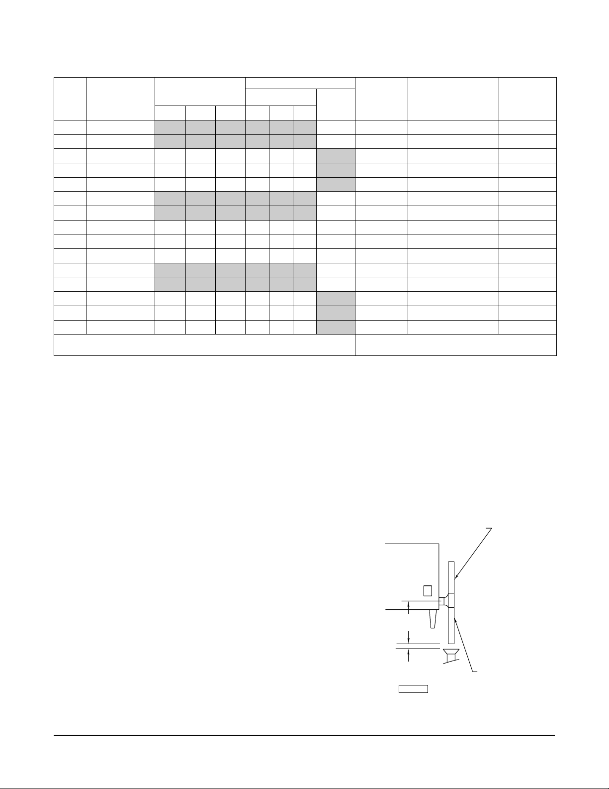
STEP 2. If the Deliming Plug is inside the cooking
compartment (Fig. 4), unscrew the plug so the hole
points upwards.
BEAKER
FUNNEL
PLASTIC TUBE
DELIMING PLUG
Fig. 4
PL-51511
ALTERNATE STEP 2. If the Deliming Plug is
outside on the left side panel (Fig. 5), remove the
top plug and turn the main power switch ON.
Fig. 5
– 15 –
Page 16

STEP 3. Insert the plastic tube in the deliming port. Connect the funnel to the other end of the tube.
Pour 28 fl.oz. of CLR liquid into the generator slowly to avoid spillage. Remove tube and funnel.
Thoroughly rinse the tube, funnel, and beaker before storing or disposing. Replace deliming plug so
it seals tightly.
STEP 4. Turn main power switch ON (if not previously done in Alternate Step 2 above). When READY
1
light comes on, wait 1
/2 hours. Turn main power switch OFF and allow to drain.
STEP 5. Turn main power switch ON. When the READY light comes on, turn main power switch OFF
to drain. Repeat this step three times to completely flush generator.
STEP 6. Clean exterior and interior. Use a mild solution of soap and water. Rinse with clean water.
Dry with a soft cloth. Leave compartment door open when not in use.
The steamer is now ready for use or can be turned off for overnight shutdown.
COLD WATER CONDENSER
The steamer is equipped with a cold water condenser in the rear of the cooking compartment which
helps to condense the steam prior to discharge into the drain.
The steamer freely vents itself by the negative pressure created by the condensate water drainage.
This negative pressure prevents steam leakage around the door gasket and helps draw the steam
through the cooking compartment.
Steam leakage at the door may indicate a plugged or improperly installed drain.
SERVICE
Contact your local Hobart-authorized service office for any repairs or adjustments needed on this
equipment.
FORM 34055 Rev. A (2-99) PRINTED IN U.S.A.
– 16 –
 Loading...