

Page 1

I
N
S
T
R
U
C
T
I
O
N
S
U, UB, AND DU SERIES
UNDERCOUNTER
FOOD STORAGE CABINETS
EXECUTIVE OFFICES
701 RIDGE AVENUE
TROY, OHIO 45374-0001
– 1 –
FORM 18953 Rev. A (11-95)
Page 2
Installation, Operation, and Care of
U, UB, AND DU SERIES
UNDERCOUNTER FOOD STORAGE CABINETS
SAVE THESE INSTRUCTIONS
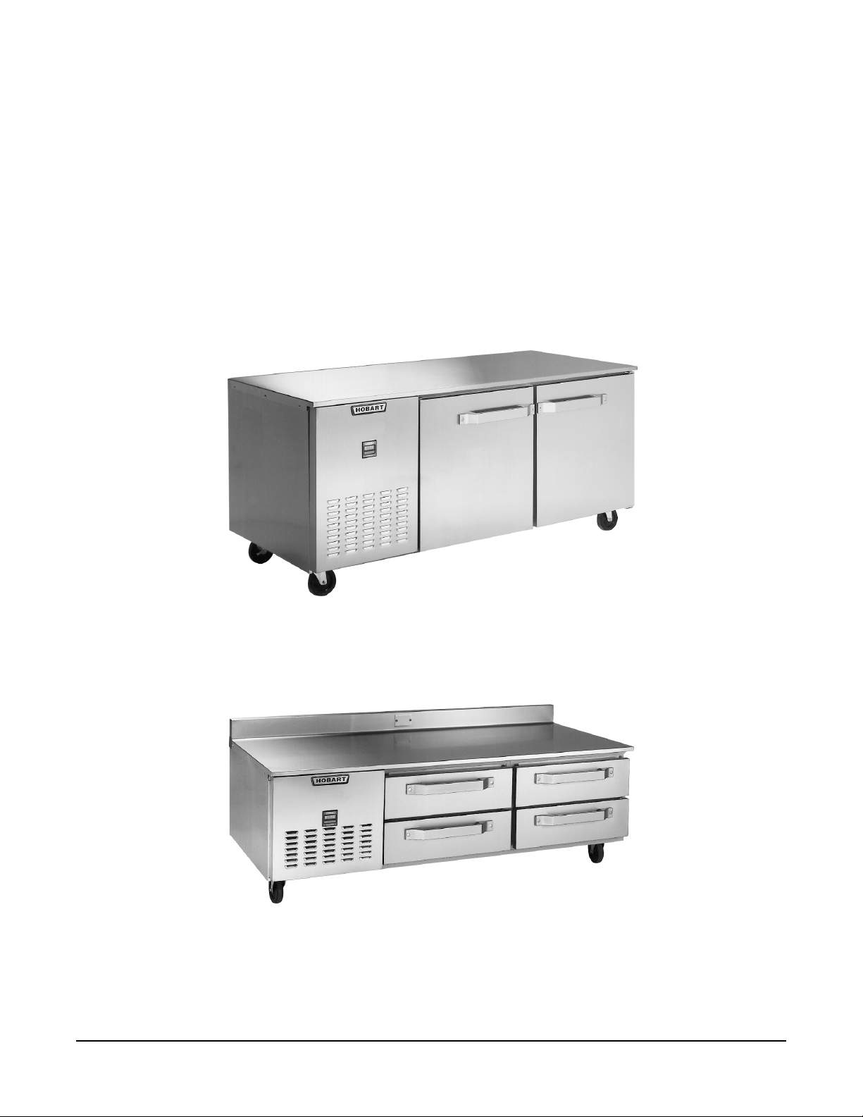
U Series cabinet with 2 door sections
UB Series cabinet with 2 drawer sections
© HOBART CORPORATION, 1994
– 2 –
Page 3
GENERAL
U, UB, and DU Undercounter Food Storage Cabinets can be equipped for freezer (0°F) or refrigerator
(38°F) operation. The condensing unit can be self-contained or remote (supplied by others). The
equipment compartment can be specified for the left- or right-side. Refrigerators use R22 refrigerant;
freezers use R502 (remote freezers may be R22 or R502).
Undercounter Food Storage Cabinets may be ordered with one-, two-, or three-sections with a door
or two drawers in each section. Pass-through cabinets are available (U Series only) with doors front
and back – no drawers. Glass doors are optional on U Series refrigerator cabinets; pass-thru cabinets
cannot have more than 50% of the doors be glass. U and UB Series drawer sections are front opening
only (not available with freezers or pass-thru cabinets).
UB Series Food Storage Cabinets are built nine inches shorter than other U Series cabinets. Ideal for
use as a refrigerated base under countertop cooking equipment, UB Series cabinets are equipped with
drawers (standard) or solid doors (optional).
U and UB Series cabinets are available with S or C material codes. In the table below, S denotes
stainless steel; C denotes silvertone PermaShield polyester coated steel; G denotes galvanized steel.
DU Series cabinets feature a combination of Alum-a-Shield, stainless steel, and galvanized steel.
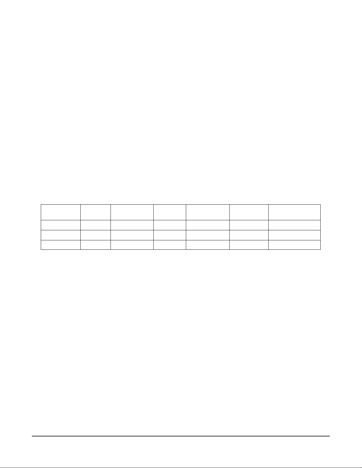
Material Codes
Interior Solid Doors Drawers System Grille Cabinet Ends
US, UBS SSS S S G
UC, UBC C C std (S opt) C C C G
DU ASS S A G
Cabinet
Top, Bottom, Rear
Optional finished panels are available to mount over the cabinet ends, top, and back. Finished end
panels are stainless steel; finished countertops (flat or with backsplash) are stainless steel; finished
back panels are av ailab le as stainless steel, silv ertone P ermaShield polyester coated steel, or Aluma-Shield. Left and Right ends are viewed from the cabinet front. Left and Right hinging is viewed from
the front of the door; optional hinging is available.
Hinged-door sections are provided with two shelves and eight shelf support clips, standard. Additional
shelves and clips are available. Heavy duty stainless steel pullout shelves are optional on U Series
door sections (front opening or pass-thru). The optional Bonus Shelf (SST or plated) extends the shelf
behind the mullion post between doors on two- and three-section cabinets. Optional interior light(s)
are available on front-opening hinged door cabinets without drawers (two-section has one light, threesection has two lights). Optional drawer sections contain two drawers per section. Each drawer can
accommodate two 12" x 20" restaurant pans (maximum depth 4" on UB models). The drawer-shelf
option provides a plated wire drawer bottom when not using restaurant pans. Food File options are
available on U Series door sections (front opening or pass-thru); Food File options are not available
on UB Series.
– 3 –
Page 4

INSTALLATION
UNPACKING
Immediately after unpacking, check for possible shipping damage. If damage is found after unpacking,
save the packaging material and contact the carrier within 15 days of delivery.
LOCATION
Condenser performance is dependent on adequate ventilation for cooling purposes. Provide at least
4" clearance at the rear of the condenser compartment on all models.
Prior to installation, test the electrical service to assure that it agrees with the specifications on the
machine data plate located in the upper front corner inside the cabinet.
LEGS OR CASTERS
WARNING: THE CABINET MUST BE BLOCKED AND STABLE BEFORE INSTALLING LEGS OR
CASTERS.
Raise up and block the cabinet a minimum of 7" from the floor. Threaded holes are provided on the
bottom of the cabinet to assemble standard legs (Fig 1). Optional Flanged Legs assemble similarly;
holes in the flanged foot are provided to allow the Flanged Legs to be secured to the floor (fasteners
by others). Optional Casters are assembled in the same way (Fig. 2). Casters may not be installed
on cabinets with remote refrigeration systems. Optional legs/casters: 4 are required per 1 or 2 section
cabinet; 6 are required per 3 section cabinet. Casters with brake should be installed on the front.
PL-50909
Fig. 1 Fig. 2
UTILITY BASE (Optional)
Place the cabinet with factory-assembled utility base in its final installed location. Secure the utility
base to the floor to prevent damage to the floor electrical outlet due to accidental movement. Apply
a bead of silicon sealant around the bottom. An access cover, secured with thumb screws, is provided
on the left side of the utility base to allow the power cord to be connected to the floor outlet underneath
the cabinet.
– 4 –
Page 5

LEVELING
Level the cabinet using a spirit level or pan of water in the bottom of the cabinet as a reference. Turn
the adjustable feet in or out to level the cabinet side-to-side and front-to-back. Units with casters or
utility bases should be placed on level floors or shimmed.
SHELVES (Figs. 3 and 4)
Shelves, shelf clips, and accessories are packed at the end of the skid. Using the index holes as a
guide for leveling, insert the shelf clips into the slots provided and install the shelves.
PILASTER
BONUS
SHELF
INDEX
HOLE
SHELF
PL-51360
SHELF
CLIP
Fig. 3 Fig. 4
NOTE: Loosen all thumb screws which secure shelf pilasters and light cover(s) prior to placing
product in cabinet. Thumb screws should be loose enough to remove with your fingers so parts can
be readily removed for cleaning without the use of tools. Failure to comply with this request will
invalidate the NSF listing.
REMOTE REFRIGERATION SYSTEMS
Remote refrigeration systems (the condensing unit is not supplied by Hobart), are provided with
thermostatic expansion valves, temperature control, (and a time clock for defrost on freezers only).
The refrigeration lines and condensate drain tube terminate in the equipment compartment. If your
equipment contains a condensate disposal system, it will be located in the equipment compartment;
otherwise, a suitable drain can be provided (by others). Refrigeration line sizes are
3
and
⁄8" O.D. Suction Line for all refrigerators and the single section UB freezer. All other freezers have
1
⁄4" O.D. Liquid Line and 1⁄2" O.D. Suction Line. Plug buttons with holes are provided in the bottom of
1
⁄4" O.D. Liquid Line
the equipment compartment for exit of refrigeration tubing and drain lines (if necessary).
– 5 –
Page 6

ELECTRICAL CONNECTIONS
Cord Connected Units
WARNING: THIS MACHINE IS PROVIDED WITH A THREE-PRONG GROUNDING PLUG. THE
OUTLET TO WHICH THIS PLUG IS CONNECTED MUST BE PROPERLY GROUNDED. IF THE
RECEPTACLE IS NOT THE PROPER GROUNDING TYPE, CONTACT AN ELECTRICIAN.
Permanently Connected Units
WARNING: ELECTRICAL AND GROUNDING CONNECTIONS MUST COMPLY WITH APPLICABLE
PORTIONS OF THE NATIONAL ELECTRICAL CODE AND/OR OTHER ELECTRICAL CODES.
WARNING: DISCONNECT ELECTRICAL POWER SUPPLY AND PLACE A TAG AT THE DISCONNECT
SWITCH INDICATING THAT YOU ARE WORKING ON THE CIRCUIT.
Refrigerators and freezers requiring permanent connection are provided with a terminal block located
7
on the side of the evaporator housing in the compressor compartment. A
panel is provided to accept a
1
⁄2" trade size conduit. A properly grounded wiring connection is required.
⁄8" diameter hole in the bottom
Refer to the wiring diagram on the panel on the front of the compressor compartment.
Remote refrigerators and freezers are equipped with a terminal block to connect the temperature
control (and time clock on freezers only) to the remote condensing unit — use copper wire only. Refer
to the wiring diagram on the panel on the front of the compressor compartment.
PRESTART CHECKS
REFRIGERANT LINES — Check for tubing shifts due to shipping that would cause operating noise,
wear, or leaks.
DEFROST TIMER — Freezer models are equipped with a Defrost Timer which provides three 23 – 25
minute defrost cycles per day; defrost cycles occur at eight hour intervals. By inserting a screwdriver
into a large hole on the panel on the front of the compressor compartment and turning clockwise, the
time of day that these cycles occur may be adjusted. It is recommended that the defrost cycles occur
during periods when the freezer doors are less frequently opened.
TEMPERATURE CONTROL — The temperature control is set at the factory, but operating conditions
may necessitate slight adjustment. To adjust the temperature control, loosen the thumb screw on the
bottom of the louvered panel (if present), lift up and remove the louvered panel, and turn the control
knob a small amount at a time. Turning the control knob in the direction of the arrow lowers the
temperature. The control knob has a marked OFF position which interrupts power to the compressor
and condenser fan only, not the entire machine.
OPERATIONAL CHECK — The refrigeration and defrost or off cycles should be checked for proper
operation before product is stored in the cabinet.
– 6 –
Page 7

OPERATION
Digital thermometer (Fig. 5), standard on U and UB Series, uses ambient light to generate a low voltage
electrical current which senses the interior cabinet temperature.
Dial thermometer (Fig. 6) is optional on U and UB Series.
Mercury thermometer (Fig. 7) is standard on DU Series.
The interior cabinet temperature is indicated by the thermometer.
Fig. 6 Fig. 7
°F °C
20
40 -40
Refrigerator
PL-51319
Fig. 5
-50
PL-51365
MAINTENANCE
CLEANING
Cabinet
Clean the inside of the cabinet and the doors weekly with a warm water solution of mild household liquid
dishwashing detergent (such as Palmolive green or Ivory). Do not use anything containing grit,
abrasive materials, bleach or harsh chemicals. Be cautious with new or improved formulas; use only
after being well tested. Rinse thoroughly and dry with a clean soft cloth.
Gaskets
Door gaskets should be cleaned weekly using a warm water solution of mild household liquid
dishwashing detergent (such as Palmolive green or Ivory). Never allow gaskets to contact concentrated
cleaners or disinfectants. This can cause premature failure of the gasket material.
Condenser Coil
WARNING: DISCONNECT ELECTRICAL POWER SUPPLY BEFORE CLEANING THE CONDENSING UNIT.
Check the condenser coil weekly. This surface must be kept free of dirt and grease for proper system
operation. Remove the front trim panel and carefully vacuum or brush dirt and lint from the condenser
coil. Replace the trim panel.
Evaporator Coil, Drain Pan, Condensate Loop, and Condensate Dish
When needed, flush these components with fresh water. This should be a part of any routine
maintenance program and can prolong the life of the equipment.
Drawers
Drawers (when equipped) may be removed for cleaning by opening the drawer and lifting it so the
drawer rollers fit through the openings in the slides. Slides may be removed similarly. After cleaning,
replace any disassembled parts.
– 7 –
Page 8

2345678901234567890123456789012123456789
0
0
0
0
0
0
0
0
0
0
0
0
0
0
0
0
0
0
0
0
0
0
0
0
0
0
0
0
0
0
0
0
0
2345678901234567890123456789012123456789
2345678901234567890123456789012123456789
Light Bulb Replacement
2345678901234567890123456789012123456789
2345678901234567890123456789012123456789
2345678901234567890123456789012123456789
Units equipped with optional interior light(s) should be replaced with 40 watt incandescent light bulbs.
2345678901234567890123456789012123456789
2345678901234567890123456789012123456789
2345678901234567890123456789012123456789
First, remove the protective cover by removing two thumb screws. Remove and replace the bulb.
2345678901234567890123456789012123456789
2345678901234567890123456789012123456789
Replace the protective cover; secure with two thumb screws.
2345678901234567890123456789012123456789
2345678901234567890123456789012123456789
2345678901234567890123456789012123456789
2345678901234567890123456789012123456789
2345678901234567890123456789012123456789
2345678901234567890123456789012123456789
2345678901234567890123456789012123456789
2345678901234567890123456789012123456789
2345678901234567890123456789012123456789
2345678901234567890123456789012123456789
2345678901234567890123456789012123456789
2345678901234567890123456789012123456789
For additional information or to discuss a maintenance program, contact your local authorized
2345678901234567890123456789012123456789
2345678901234567890123456789012123456789
refrigeration servicer.
2345678901234567890123456789012123456789
2345678901234567890123456789012123456789
2345678901234567890123456789012123456789
2345678901234567890123456789012123456789
2345678901234567890123456789012123456789
2345678901234567890123456789012123456789
2345678901234567890123456789012123456789
2345678901234567890123456789012123456789
FORM 18953 Rev. A (11-95) PRINTED IN U.S.A.
– 8 –
 Loading...