

Hobart 486259 Operation And Maintenance Manual
OM-238
071582
Revised
050586
i 4
OPERATION AND MAINTENANCE MANUAL
with
ILLUSTRATED PARTS LIST
for
Low Profile Gate Box
Part Number 486259
HOBART BROTHERS COMPANY
POWER SYSTEMS DIVISION
TROY, OHIO 45373
U.S.A.

SAFETY INSTRUCTtONS AND WARNINGS FOR ELECTRICAL POWER EQUIPMENT
ELECTRIC SHOCK can kill. Do not touch live electrical parts.
FUMES AND GASES can be fire and health hazards. Ventilate all fumes and exhaust gases to the outside.
ELECTRIC ARC FLASH can injure eyes, burn skin, cause equipment damage, and ignite combustible material. Do not
use power cables to break load and be sure tools don’t cause short circuits.
IMPROPER PHASE CONNECTION, PARALLELING, OR USE can damage this and attached equipment.
MOVING PARTS can cause serious injury. Keep clear of moving parts.
IMPORTANT -
A. GENERAL
Protect yourself and others. Read and understand all the instructions in this Operating/Instruction
Manual before installing, operating, or servicing this equipment. Keep this manual available for future
use by all operators.
Equipment that supplies electrical power can cause serious injury or death, or damage to other equipment or
property, if the operator does not strictly observe all safety rules and take precautionary actions. Safe practices
have developed from past experience in the use of power source equipment. Certain of the practices below apply to
engine driven equipment.
B. SHOCK PREVENTION
Bare conductors, or terminals in the output circuit, or ungrounded, electrically-live equipment can fatally shock a
person. Have a competent electrician verify that the equipment is adequately grounded and learn what terminals
and parts are electrically HOT. Use proper safety clothing, procedures, and test equipment.
The electrical resistance of the body is decreased when wet, thus more easily permitting dangerous currents to flow
through it. When inspecting or servicing equipment, do not work in damp areas without being extremely careful.
Stand on dry rubber mat or dry wood, use insulating gloves that are effective when dampness or sweat cannot be
avoided. Keep your clothing dry and never work alone.
1. Installation and Grounding of Electrically Powered Equipment - Electrical equipment must be installed
and maintained in accordance with the National Electrical Code, ANSI/NFPA 70, and other applicable codes.
A power disconnect switch or circuit breaker must be located at the equipment. Check the nameplate for voltage,
frequency, and phase requirements. If only 3-phase power is available, connect any single-phase rated equipment to
only two wires of the 3-phase line. DO NOT CONNECT the equipment grounding conductor (lead) to the third live
wire of the 3-phase line, as this makes the equipment frame electrically HOT, which can cause a fatal shock.
-- ------
Be sure to connect the grounding lead, if supplied in a power line cable, to the grounded switch box or building
ground. If not provided, use a separate grounding lead. Be certain that the current (amperage) capacity of the
grounding lead will be adequate for the worst fault current situation. Refer to the National Electrical Code ANSI/
NFPA 70 for details. Do not remove plug ground prongs. Use correct mating receptacles.
2. Output Cables and Terminals - Inspect cables often for damage to the insulation and the connectors. Replace
or repair cracked or worn cables immediately. Do not overload cables. Do not touch output terminal while equipment is energized.
Instruction 910082
Nov 16/82 Revised
Page 1
FIRE AND EXPLOSION PREVENTION
Fire and explosion are caused by electrical short circuits, combustible material near engine exhaust piping, misuse
of batteries and fuel, or unsafe operating or fueling conditions.
1.
Electrical Short Circuits and Overloads - Overloaded or shorted equipment can become hot enough to cause
fires either by self destruction or causing nearby combustibles to ignite. Provide primary input protection to remove short circuited or heavily overloaded equipment from the line.
2. Battery - Batteries may explode and/or give off flammable hydrogen gas. The acid and arcing from a ruptured
battery can cause fires and additional failures. When servicing, do not smoke, causing sparking, or use open flame
near the battery.
3. Enqine Fuel - Use only approved fuel container or fueling system. Fires and explosions can occur if the fuel
tank is not grounded prior to and during fuel transfer. Shut unit DOWN before removing fuel tank cap. Do not
completely fill tank. Heat from the equipment may cause fuel expansion overflow. Remove all spilled fuel immediately including any that penetrates the unit. After cleanup, open equipment doors and blow fumes away with
compressed air.
D.
E.
F.
TOXIC FUME PREVENTION
Carbon Monoxide - Engine exhaust fumes can kill and cause health problems. Pipe or vent the exhaust fumes to a
suitable exhaust duct or outdoors. Never locate engine exhausts near intake ducts or air conditioners.
BODILY INJURY PREVENTION
Serious injury can result from contact with fans, belts, and pulleys inside the equipment. Shut DOWN equipment
for inspection and routine maintenance. When equipment is in operation use extreme care in doing necessary
troubleshooting and adjustment.
MEDICAL AND FIRST AID TREATMENT
First aid facilities and a qualified first aid person should be available for each shift for immediate treatment of all
injury victims. Electric shock victims should be checked by a physician and taken to a hospital immediately if any
abnormal signs are observed.
EMERGENCY FIRST AID
Call physician immediately. Seek additional assistance and use First Aid techniques recommended
by American Red Cross until medical help arrives.
IF BREATHING IS DIFFICULT, give oxygen, if available, and have victim lie down. FOR ELECTRICAL SHOCK, turn off power. Remove victim; if not breathing, begin artificial respiration,
preferably mouth-to-mouth. If no detectable pulse, begin external heart massage. Call Emergency
Rescue Squad immediately.
G.
EQUIPMENT PRECAUTIONARY LABELS
3. Service and Maintenance -
This equipment must be maintained in good electrical and mechanical condition
to avoid hazards stemming from disrepair. Report any equipment defect or safety hazard to your supervisor and
discontinue use of the equipment until its safety has been assured. Repairs should be made by qualified personnel
only. Shut OFF all power at the disconnecting switch or line breaker before inspecting or servicing the equipment.
Lock switch OPEN (or remove line fuses) so that power cannot be turned ON accidentally. Disconnect power to
equipment if it is out of service. If troubles
P .
ooting must be done with the unit energized, have present another per-
son trained in turning off the equipment and provrding or calling for first aid.
Inspect all precautionary labels on the equipment monthly. Order and replace all labels that cannot be easily read.
Page 2
Instruction 910082
Revised Nov 16/82
INTRODUCTION
OM-238
1. Scope
This manual contains operating and maintenance instructions for a series of AC Gate Boxes manufactured by Hobart Brothers Company, Power Systems Division, Troy, Ohio 45373, U.S.A.
2. Purpose
The purpose of the manual is to provide information and instructions to experienced operators, electricians and
technicians who have not previously been exposed to this equipment. The manual is not intended to be a textbook on electricity or electronics.
3. Arrangement
The manual is divided into 6 chapters. Each chapter is divided into sections as required. Each section begins with
page 1, and each page is identified by chapter, section and page number in the lower outside corner. Illustration
numbering is also grouped by sections.
When a reference is made to material which is located in the same section, the material is identified by paragraph
location only; example: (Para. 1, AI. When referenced material appears in a different section, it is identified by
chapter, section and paragraph location; example: (2-I; Para. 1, A). The same method applies to illustrations
which are identified by figure numbers; examples: (Fig. 81, or (2-l ; Fig. 8).
4. Service Information
If you have any questions concerning your Hobart Power Systems Division equipment, you are invited to contact
our Service Department by mail, telephone or TWX.
i 4
July 15182
Write:
Call:
TWX:
Hobart Brothers Company
Power Systems Division
Service Department
Troy, Ohio 45373
U.S.A.
Area Code (513) 339-6011
Extension 4276
81 O-456-2907
Introduction
Page l/2

TABLE OF CONTENTS
OM-238
SUBJECT
Introduction
Description/Operation
Description
1. General
2. Detailed Description
A. Enclosure
B. Internal Components
(1) Vacuum contactor panel
(a) Vacuum contactor
(b) High voltage fuse panel
(cl Control transformer
(d) Power supply
i ;I
CHAPTER/SECTION PAGE
1-o
l-l
1
6
6
6
6
(e) Power supply fuse
(2) Harmonic filter
(3) Stepdown transformer
(4) Line drop compensator
C. Circuit Breaker
Preparation for Use
1.
Receipt of Equipment
2. Installation
A. Mounting
B. Input Cables
C. Output Cables
D. Grounding
1-2
7
7
7
7
7
1
July 15182
Contents
Page 1
SUBJECT
CHAPTER/SECTION
OM-238
TABLE OF CONTENTS (CONTINUED)
3. Preoperational Check
Operation
1. General
2. Power Delivery
3. Discontinue Power Delivery
Servicing
Maintenance
1. General
2. Lubrication
3. Parts Replacement
4. Lamps and Fuses
A. Lamps
B. Fuses
Inspection/Check
1. General
2. Inspection
Adjustment/Test
1.
Adjustment
A. Line Drop Compensator
B. Tuning Harmonic Filters
(1) Reactors
(2) Variable resistors
2. Test
A. Vacuum Contactor
PAGE
1-2
4
i ;,
1-3
1
1
,I
1
Contents
Page 2
2-o
2-1
2-2
2-3
II2
I/:!
l/2
l/2
l/2
112
112
112
l/2
l/2
112
July 15182
I
I
OM-238
TABLE OF CONTENTS (CONTINUED)
SUBJECT
CHAPTER/SECTION
PAGE
B. Contactor Control Circuit
2-3
5
i ‘I
5
C. Harmonic Filter
D. Stepdown Transformer
E. Line Drop Compensator
(1) Preparation for test
(2) Test procedures
Troubleshooting
Introduction
1. General
Illustrated Parts List
Introduction
1. General
2. Purpose
3. Arrangement
4. Explanation of Parts List
A. Contents
B. Parts List Form
(1) Figure-kern No. Column
3-o
3-1
4-o
4-I
(2) Hobart Part Number Column
(3) Nomenclature Column
(4) Rec. Spares Column
(5) Eff (Effective) Column
(6) Units Per Assembly Column
1
1
1
1
1
1
1
1
1
1
1
1
2
July 15/82
Contents
Page 3
OM-238
TABLE OF CONTENTS (CONTINUED)
SUBJECT
Manufacturer’s Codes
i 4
1.
Explanation of:Manufacturer’s (Vendor) Code List
Parts List
1.
Explanation of Parts List Arrangement
2. Symbols and Abbreviations
Low Profile Gate Box Assembly
Interior Group
5
Contactor Panel Assembly
Harmonic Filter Capacitor Assembly
Line Drop Compensator Control Assembly
Circuit Breaker Group
Optional Equipment
Manufacturer’s Literature
CHAPTE RI FIGURE
SECTION NUMBER
I-l
1 Low Profile Gate Box
2
I-l 2 Specifications and Capabilities
3
l-l 3 Internal Components
4
I-l
4
Vacuum Contactor Panei Assembly
5
l-l 5 Transformer-Rectifier Assembly
6
I-l
6 Harmonic Filters 8
l-l 7
Line Drop Compensator
9
I-l 8 Circuit Breaker and Enclosure
10
1-2
1-2
1-2
I-3
LIST OF ILLUSTRATIONS
TITLE
Outline and Mounting Dimensions
Input Cable Connection Terminals
Circuit Breaker Output Connections
Input Power Controls
CHAPTER/SECTION
4-2
PAGE
1
1
7
9
11
13114
5-o
If2
6-O
l/2
PAGE
NO.
2
3
4
2
Contents
Page 4
July Ii/82
w
1
OM-238
CHAPTE RI
FIGURE
SECTION NUMBER
2-1
1
2-2 None
2-3 1
L.D.C. Overload Adjustment
2
2-3 2
Harmonic Filters 4
2-3 3
Gate Box Components
6
2-3
4
Contactor Panel 7
2-3
5
Power Supply Transformer Rectifier 8
2-3 6
Line Drop Compensator IO
2-3 7
Harmonic Filter Circuits 1 II12
3-l 1
Contactor Panel 2
3-I
2
Gate Box Components
3
3-I
3
Transformer-Rectifier Assembly
4
3-l 4
Line Drop Compensator 5
3-1
5
Troubleshooting Chart (4 Sheets)
6 thru 9110
4-3 1
Low Profile Gate Box
2
4-3
2
Interior Group 4
4-3 3
Contactor Panel Assembly
6
4-3 4
Harmonic Filter Capacitor Assembly
8
4-3
5
Line Drop Compensator Control Assembly 10
4-3
6
Circuit Breaker Group
12
July 15182
LIST OF ILLUSTRATIONS (CONTINUED)
TITLE
i 1
Fuse Chart
PAGE
NO.
II2
Contents
Page 516

OM-238
CHAPTER 1. DESCRIPTION/OPERATION
SECTION 1. DESCRIPTION
1. General
i ;,
This manual provides the information required to install, operate, and maintain the Low Profile Gate Box (Fig. I)
manufactured by Hobart Brothers Company, Power Systems Division, Troy, Ohio 45373 U.S.A.
These gate boxes are identified by Hobart part number 486259 and are rated at 90 kVA, with 4160 volts AC,
400 Hz input and 12Ol200 volts AC, 400 Hz output. Refer to Figure 2 for detailed specifications and character-
istics.
Each unit consists of a sheet metal enclosure which houses a large stepdown transformer and additional electrical
and electronic equipment required to condition and control the output circuit.
Two pushbuttons and a pilot light control the 4160 volt input circuit, and a manually controlled circuit breaker
controls the 120/200 volt output circuit.
A welded steel base provides support for the internal subassemblies, and is designed to be mounted on a level
concrete pad.
2. Detailed Description
A. Enclosure
The 11 gage sheet metal enclosure which houses the components consists of four side and end panels and a
top cover. The side and end panels are bolted together at the corners, with their bottom flanges bolted to the
welded steel base. The top cover is bolted to the panels.
Both side panels and one end panel are fitted with access panels to permit inspection and servicing of the
internal components without removing the top or side panels. Each access panel has ventilating louvers to per-
mit the free flow of air for convection cooling of the internal components. Cool air enters the unit through
openings in the base, circulates over the internal components, and is expelled through the louvers in the
access panels. The output circuit breaker is housed in its own enclosure, which is bolted to the output end
panel.
B. Internal Components
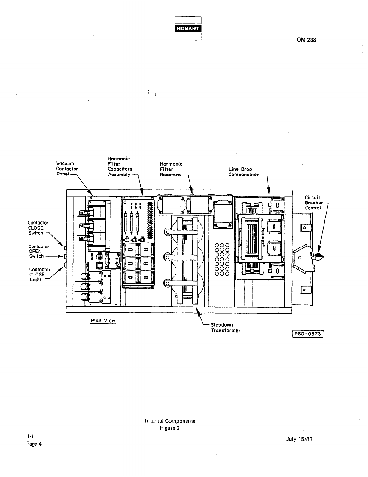
Refer to Figure 3. This illustration shows the gate box with its enclosure removed to locate all internal sub-
assemblies which are mounted on the base.
(I) Vacuum contactor panel
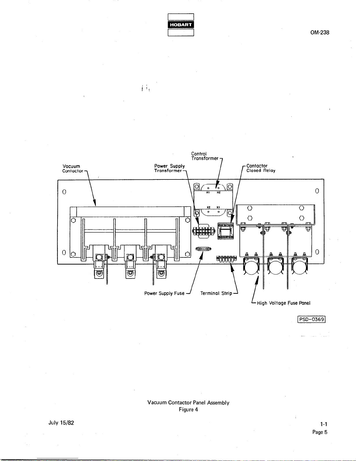
Refer to Figure 4. The vacuum contactor panel is the first subassembly in the gate box at the input end.
Its base panel provides mounting for the high voltage fuse panel, the vacuum contactor, and other power
control and conditioning components described below.
July 15182 l-l
Page 1
OM-238
Low Profile Gate BOX
Figure 1
July 15/82
l-l
Page 2
OM-238
PHYSICAL
Length
87-3/8 inches (2219 mm)
Width
i ;I
44 inches (1118 mm)
Height
24 inches (610 mm)
Weight (approx.)
2500 pounds (1134 kg)
ELECTRICAL
Volts (AC)
Frequency (Hz)
Phase
Current (Amps)
output
4160
400,
3
12.4
Volts (AC)
Frequency (Hz)
Phase
Current (Amps)
Transformer
115/200
400
3
249
Input
Volts (AC)
Current (Amps)
Phase
Frequency (Hz)
Power (kVA)
Duty
output
4160
12.4
3
400
90
Continuous
Volts (AC) (Open Circuit, No Load)
Current (Amps)
Phase
Frequency (Hz)
Power (kVA)
Full Wave
Temperature Rise (Degrees Cl
Connection
Primary: Delta
Secondary: 4 Wire Wye
1201208
249
3
400
90
115
Specifications and Capabilities
Figure 2
July 15182
I-l
Page 3
w
I 1
OM-238
Vacuum
Contactor
Panel
Harmonic
Filter
Capacitors
Assembly
7
Harmonic
Filter
Reactors
7
Line Drop
Compensator
--I
Contactor
CLOSE
Switch __c#
Plan View
L
Stepdown
Transformer
Circuit
Internal Components
Figure 3
l-l
Page 4
July 15/82
Control
OM-238
July 15/82
Power Supply Fuse J
Vacuum Contactor Panel Assembly
Figure 4
Terminal Strip -\
L
High Voltage Fuse Panel
l-l
Page 5
I
m
OM-238
(a) Vacuum contactor
The vacuum contactor controls the high voltage power into the gate box. Its main contacts are
opened and closed by the contactor CLOSE and contactor OPEN switches on the input end of the
gate box enclosure. It is monitored by the contactor CLOSE light mounted next to the switches. The
main contacts, which control the 4166 volt input, operate in a vacuum to eliminate arcing and flash.
t ‘I
Their initial closing is accomplished through the contactor control relay which is mounted beside the
contactor. After their initial closing, they are held closed by a smaller set of auxiliary contacts in the
contactor. These auxiliary contacts are connected in parallel with the contactor CLOSE switch,
which closes them at.the same time that the main contacts are closed.
(b) High voltage fuse panel
The high voltage fuse panel provides three 20 ampere fuses which protect the stepdown transformer.
(c) Control transformer
The control transformer receives 4160 volts AC, tapped from the input power line, and reduces it to
115 volts AC for use by the power supply.
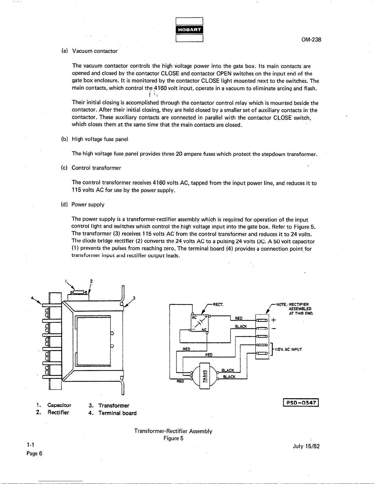
(d) Power supply
The power supply is a transformer-rectifier assembly which is required for operation of the input
control light and switches which control the high voltage input into the gate box. Refer to Figure 5.
The transformer (3) receives 115 volts AC from the control transformer and reduces it to 24 volts.
The diode bridge rectifier (2) converts the 24 volts AC to a pulsing 24 volts DC. A 50 volt capacitor
(1) prevents the pulses from reaching zero. The terminal board (4) provides a connection point.for
transformer input and rectifier output leads.
1. Capacitor
3. Transformer
2. Rectifier
4. Terminal board
I ISI. AC INPUT
I-l
Page 6
Transformer-Rectifier Assembly
Figure 5
July 15/82
I
m
I I
OM-238
(e) Power supply fuse
This 1 ampere fuse protects the power supply from any overvoltage out of the control transformer.
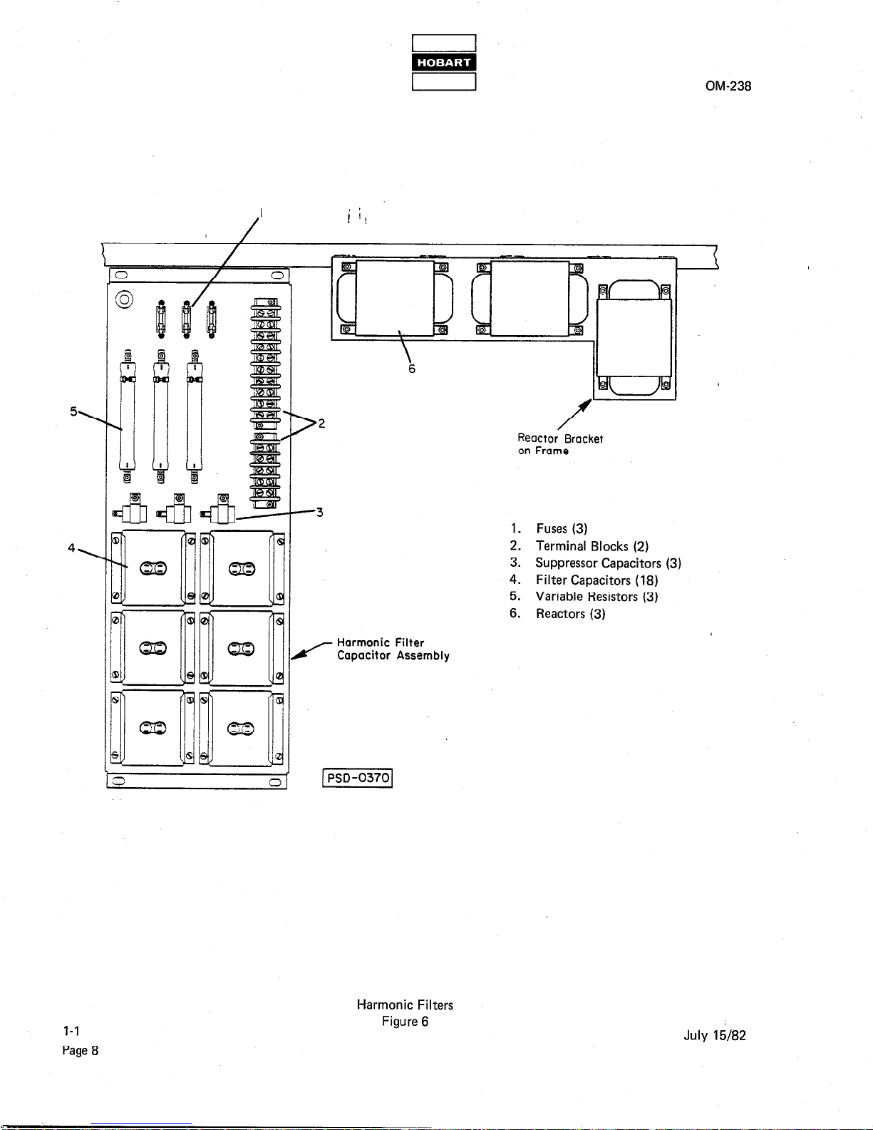
(2) Harmonic filter
i 4
Refer to Figure 6. The harmonic filter network (per phase) consists of a variable resistor (5), capacitor
bank (4). and a tapped inductor (6). The filter is connected to the output of the line drop compensator.
1
The purpose of the harmonic filters is to eliminate, or suppress to an acceptable level, the harmonic
voltages produced by an aircraft (or load) while utilizing 400 Hz power.
The principle of operation of the filter is based on a parallel resonant circuit, with resonance at 400 Hz.
At this resonant frequency (400 Hz), the circuit acts like a high impedance. Above this resonant frequency, the circuit acts like an R-C network, passing the higher frequency voltages. The function of
the variable resistance is to reduce the overall gain of the filter where a series resonance could occur
between filter and generator harmonic impedance. This resistor should only be adjusted once in the
operating system to account for generator and cable impedances.
The three capacitors (3, Fig. 6) are spike suppressors and are not part of the filter network.
The three fuses (1) protect the filter network in situations of extremely high harmonic content where
the level of filtered harmonic currents exceed a safe level, or in the event of catastrophic failure of any
component.
(3) Stepdown transformer
This large transformer, located in the center of the gate box, reduces the 4160 volts AC input power to
120/200 volts AC for routing to the line drop compensator. Complete specifications on this transformer
are included in Figure 2.
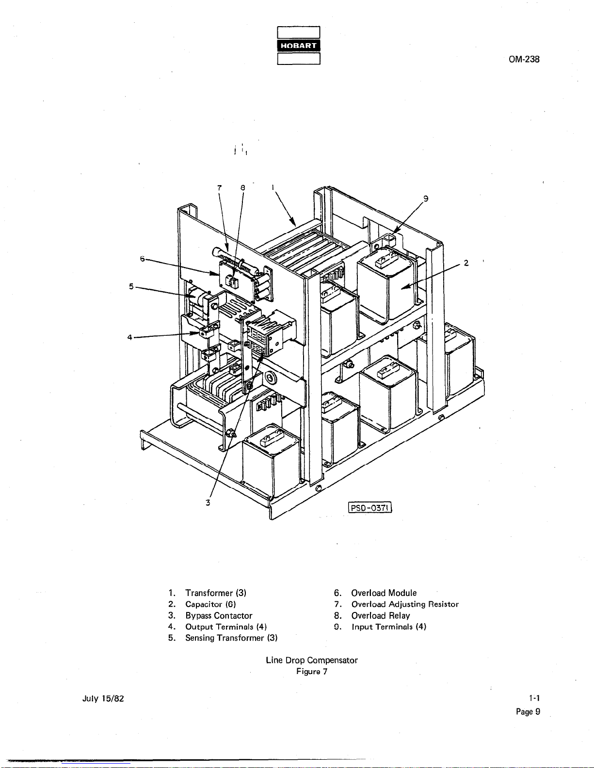
(4) Line drop compensator
Refer to Figure 7. The line drop compensator in this gate box is rated at 90 kVA, 260 amperes. It is
identical in performance to Hobart’s standard unit (Part No. 481825B-I), but has been modified
physically for this application. The purpose of the line drop compensator is to eliminate reactive volt-
age losses (line drop) in long runs of 400 Hz distribution cables; up to 5000 feet (1.524 km) under cer-
tain conditions. This unit introduces a capacitive reactance into the circuit which counteracts the in-
ductive loss and maintains a voltage value at the output end of the cable which is very close to the input
value. There will always be a resistive loss in any cable which can never be compensated for.
It may also be used for shorter cable runs to reduce the number, and/or size, of cables required.
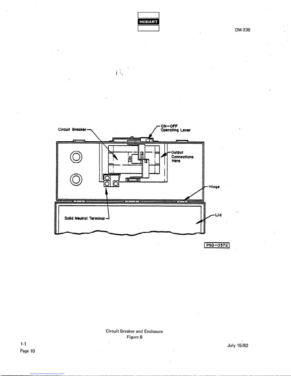
C. Circuit Breaker
Refer to Figure 8. The circuit breaker, rated at 400 amperes, 600 volts, is housed in a separate enclosure
mounted on the output end of the gate box. This manually operated switch controls the 115/200 volt output of the gate box. Two spring-loaded clamps secure the hinged lid of the enclosure in the closed position.
The enclosure is a NEMA 12 box with neoprene gaskets added to insure that its lid will be weather tight.
An external lever on top of the box permits turning the circuit breaker ON and OFF without opening the
lid. The lid may be padlocked closed, and the lever may be padlocked in the OFF position.
July 15182
l-l
Page 7
‘&
1
2
>
/
Reactor Bracket
on Frame
OM-238
Harmonic Filter
L/- Capacitor Assembly
(PSD-03701
1. Fuses (3)
2.
Terminal Blocks (2)
3.
Suppressor Capacitors (3)
4.
Filter Capacitors (18)
5. Variable Resistors (3)
6. Reactors (3)
I-l
Page 8
Harmonic Filters
Figure 6
July 15182
OM-238
1. Transformer (3)
2. Capacitor (6)
3. Bypass Contactor
4. Output Terminals (4)
5. Sensing Transformer (3)
6. Overload
Module
7. Overload
Adjusting
Resistor
8. Overload
Relay
9. Input Terminals (4)
Line Drop Compensator
Figure 7
July 15182
1-I
Page 9
w
I 1
4
! ‘I
Circuit Breakers
/-
ON-OFF
Operating Lever
0
0
1 i I I I
Solid Neutral Terminal 4
Circuit Breaker and Enclosure
Figure 8
OM-238
-Hinge
/-Lid ’
l-l
Page 10
July 15182
OM-238
SECTION 2. PREPARATION FOR USE
1. Receipt of Equipment
Check the equipment received against the shipping papers to make sure that the shipment is complete. Check the
equipmentfor shipping damage. If t P e( equipment was damaged in transit, notify the carrier at once and file a
claim for damages. If you need assistanlce with a damage claim or if the shipment is in error, furnish full information to Hobart Brothers Company at the address given in the Introduction of this manual.
It is recommended that the unit be uncrated as close to the installation site as possible. Use care in uncrating to
avoid damaging the equipment with tools. Lift and transport the gate box ONLY with a suitable forklift, using
the two reinforced openings in the base. The assembly weighs approximately 2500 pounds (1134 kg).
2. Installation
The gate box may be installed outdoors without further protection. The ventilating louvers in the enulosure are
rainproof.
A. Mounting
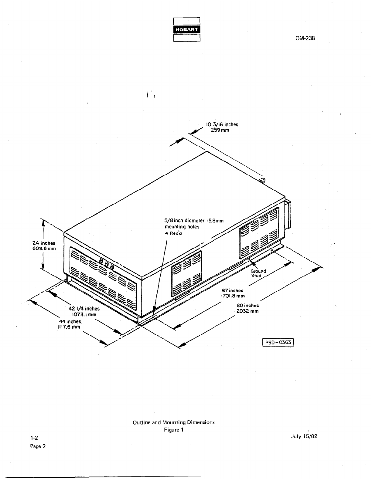
The gate box base is designed to be mounted on a level concrete pad. Figure 1 illustrates the outline package
dimensions of the unit, as well as the hole pattern in the bottom flange of the base. Locate four threaded studs
or lag bolts to the dimensions shown to secure the gate box in position.
B. Input Cables
WARNING: MAKE SURE THAT INPUT POWER IS OFF AND CANNOT BE TURNED ON
ACCIDENTALLY. OTHERWISE, LETHAlELECTRICAL SHOCK HAZARD
EXISTS.
It is recommended that a fused disconnect switch be installed in the input power line to deenergize the gate
box for service or repair.
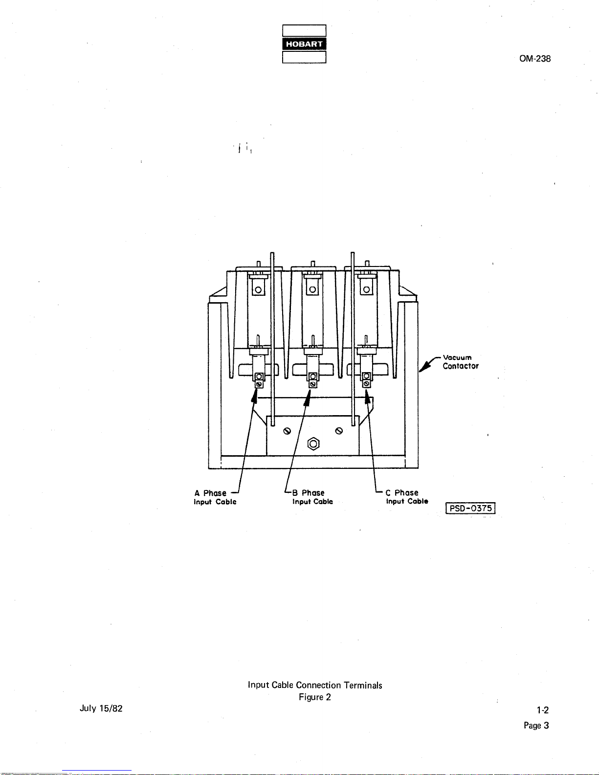
Input cables into the gate box should be brought in from below, through the opening in the base, and connected to the input cable lugs on the vacuum contactor (see Figure 2). Each cable lug will accommodate a
cable size range of one No. 14 to No. 2 AWG copper or aluminum cable. Remove the access panel to make
these connections.
C. Output Cables
WARNING: MAKE SURE THAT INPUT POWER IS OFF AND CANNOT BE TURNED ON
ACCIDENTALLY. OTHERWISE, LETHALELECTRICAL SHOCK HAZARD
EXISTS.
Connection of output cables must be made to the circuit breaker inside the separate enclosure at the output
end of the gate box. Circuit breaker terminal lugs will each accommodate a cable size range of one No. 1
AWG to 600 MCM or two No. l/O to 250 MCM copper or aluminum cables. The neutral terminal lugs will
accommodate two No. 3/O to 600 MCM or four No. 3/O to 250 MCM copper or aluminum cab!es.
There are no holes or knockouts provided in the circuit breaker enclosure. Therefore, suitable holes must be
drilled in the bottom or end of the box for output cable entry.
July 15182 l-2
Page 1
IO 3/16 inches
d
259 mm
OM-238
5/6 inch diameter 15.8mm
mounting holes
4 Req’d
/
l-2
Page 2
Outline and Mounting Dimensions
Figure 1
July 15/82
‘&
I
OM-238
L
A Phase -I LB Phose
input Coble Input Cable
LC Phase
Input Cable
K
Vacuum
Cantactor
lPSD-0375’
July 15182
Input Cable Connection Terminals
Figure 2
1-2
Page 3
m
I I
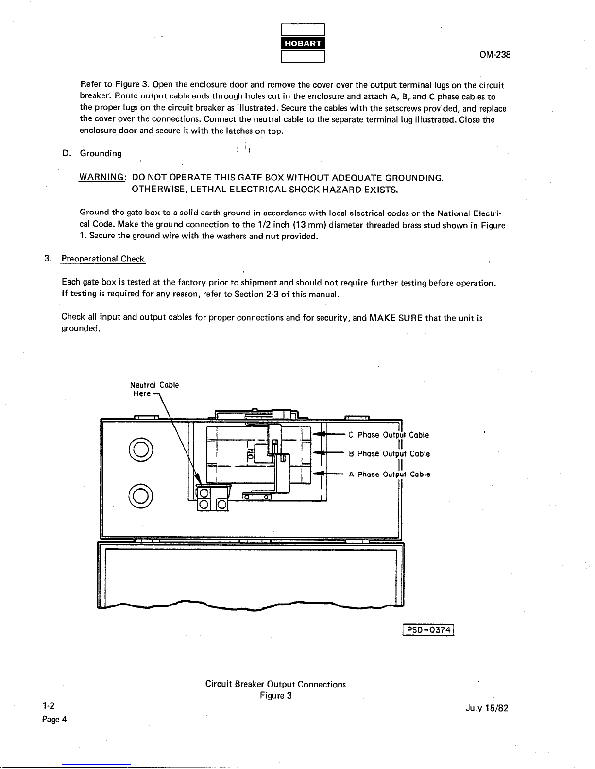
Refer to Figure 3. Open the enclosure door and remove the cover over the output terminal lugs on the circuit
breaker. Route output cable ends through holes cut in the enclosure and attach A, B, and C phase cables to
the proper lugs on the circuit breaker as illustrated. Secure the cables with the setscrews provided, and replace
the cover over the connections. Connect the neutral cable to the separate terminal lug illustrated. Close the
enclosure door and secure it with the latches on top.
D. Grounding
WARNING: DO NOT OPERATE THIS GATE BOX WITHOUT ADEQUATE GROUNDING.
OTHERWISE, LETHAL ELECTRICAL SHOCK HAZARD EXISTS.
Ground the gate box to a solid earth ground in accordance with local electrical codes or the National Electrical Code. Make the ground connection to the l/2 inch (13 mm) diameter threaded brass stud shown in Figure
1. Secure the ground wire with the washers and nut provided.
3.
Qreoperational Check
Each gate box is tested at the factory prior to shipment and should not require further testing before operation.
If testing is required for any reason, refer to Section 2-3 of this manual.
Check all input and output cables for proper connections and for security, and MAKE SURE that the unit is
grounded.
OM-238
Neutrol Cable
Here
7
Cable
Cable
Cable
1-2
Page 4
Circuit Breaker Output Connections
Figure 3
July 15/82
 Loading...