

Page 1
SERVICE MANUAL
MANUEL D'ENTRETIEN
WARTUNGSHANDBUCH
CAUTION:
Beforeservicing this chassis, itisimportantthat the servicetechnician read the“Safe ty
Precautions”and“ProductSafetyNotices”inthisservicemanual.
SM0100
AXF100E
AXF100EBS
AXF100UC
AXF100W
AXF100WUN
Data contained within this Service
manual is subject to alteration for
improvement.
ATTENTION:
Avantd’effectuerl’entretienduchâassis,letechniciendoitlireles«Précautionsdesécurité»
etles«Noticesdesécuritéduproduit»présentésdansleprésentmanuel.
VORSICHT:
VorÖffnendesGehäuseshatderService-Ingenieurdie„Sicherheitshinweise“und„Hinweise
zurProduktsicherheit“indiesemWartungshandbuchzulesen.
Les données fournies dans le présent
manueld’entretienpeuventfairel’objet
demodificationsenvuedeperfectionner
leproduit.
Die in diesem Wartungshandbuch
enthaltenenSpezifikationenkönnensich
zwecksVerbesserungenändern.
CONTENTS
SPECIFICATIONS...............................................................................................................................................3
SERVICE POINTS..............................................................................................................................................4
WIRING DIAGRAM.............................................................................................................................................8
PRINTED WIRING BOARD...............................................................................................................................9
CIRCUIT DIAGRAM...........................................................................................................................................17
BLOCK DIAGRAM.............................................................................................................................................29
EXPLODED VIEW.............................................................................................................................................31
REPLACEMENT PARTS LIST..........................................................................................................................35
SPECIFICATIONSANDPARTS ARE SUBJECT TO CHANGE FOR IMPROVEMENT
MINI COMPONENT HI-FI SYSTEM
September 2000
Page 2

ENGLISH
SAFETY PRECAUTIONS
WARNING: The following precautions must be observed.
ALL PRODUCTS
Before any service is performed on the chassis an
isolation transformer should be inserted between the
power line and the product.
1. When replacing the chassis in the cabinet, ensure
all the protective devices are put back in place.
2. When service is required, observe the original
lead dressing. Extra precaution should be taken to
ensure correct lead dressing in any high voltage
circuitry area.
3. Many electrical and mechanical parts in
HITACHI products have special safety related
characteristics. These characteristics are often not
evident from visual inspection, nor can the
protection afforded by them necessarily be
obtained by using replacement components rated
for higher voltage, wattage, etc. Replacement
parts which have these special safety
characteristics are identified by marking with a
on the schematics and the replacement parts
list.
The use of a substitute replacement component
that does not have the same safety characteristics
as the HITACHI recommended replacement one,
shown in the parts list, may create electrical
shock, fire, X-radiation, or other hazards.
4. Always replace original spacers and maintain lead
lengths. Furthermore, where a short circuit has
occurred, replace those components that indicate
evidence of overheating.
5. Insulation resistance should not be less than 2M
ohms at 500V DC between the main poles and
any accessible metal parts.
6. No flashover or breakdown should occur during
the dielectric strength test, applying 3kV AC or
4.25kV DC for two seconds between the main
poles and accessible metal parts.
7. Before returning a serviced product to the
customer, the service technician must thoroughly
test the unit to be certain that it is completely safe
to operate without danger of electrical shock. The
service technician must make sure that no
protective device built into the instrument by the
manufacturer has become defective, or
inadvertently damaged during servicing.
CE MARK
1. HITACHI products may contain the CE mark on
the rating plate indicating that the product
contains parts that have been specifically
approved to provide electromagnetic
compatibility to designated levels.
2. When replacing any part in this product, please
use only the correct part itemised in the parts list
to ensure this standard is maintained, and take
care to replace lead dressing to its original state,
as this can have a bearing on the electromagnetic
radiation/immunity.
PICTURE TUBE
1. The line output stage can develop voltages in
excess of 25kV; if the E.H.T. cap is required to be
removed, discharge the anode to chassis via a
high value resistor, prior to its removal from the
picture tube.
2. High voltage should always be kept at the rated
value of the chassis and no higher. Operating at
higher voltages may cause a failure of the picture
tube or high voltage supply, and also, under
certain circumstances could produce X-radiation
levels moderately in excess of design levels. The
high voltage must not, under any circumstances,
exceed 29kV on the chassis (except for projection
Televisions).
3. The primary source of X-radiation in the product
is the picture tube. The picture tube utilised for
the above mentioned function in this chassis is
specially constructed to limit X-radiation. For
continued X-radiation protection, replace tube
with the same type as the original HITACHI
approved type
4. Keep the picture tube away from the body while
handling. Do not install, remove, or handle the
picture tube in any manner unless shatterproof
goggles are worn. People not so equipped should
be kept away while picture tubes are handled
LASERS
If the product contains a laser avoid direct exposure to
the beam when the cover is open or when interlocks are
defeated or have failed.
Page 3
AX-F100
• The caution labels on laser usage • Notices de précautions d’emploi du laser
CLASS 1 LASER PRODUCT
LUOKAN 1 LASERLAITE
KLASS 1 LASERAPPARAT
CLASS 1 LASER PRODUCT
LUOKAN 1 LASERLAITE
KLASS 1 LASERAPPARAT
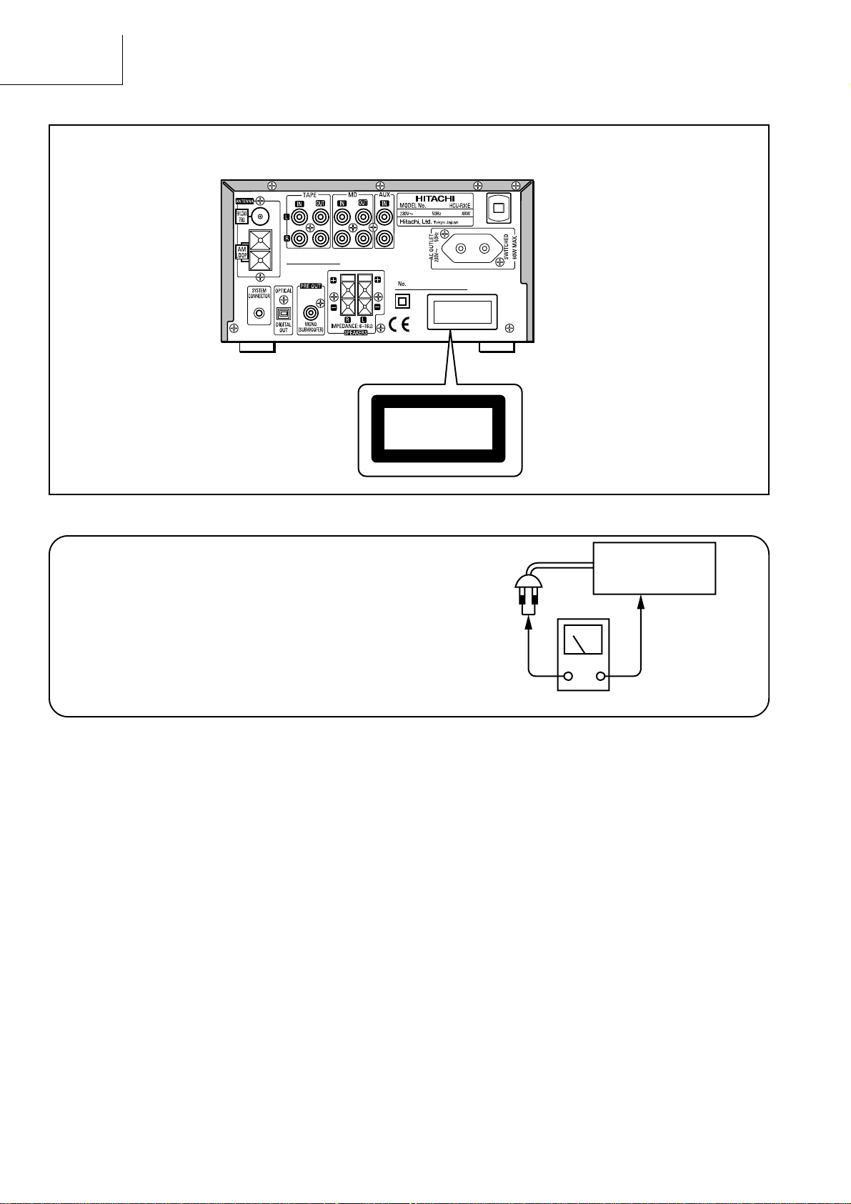
Check that exposed parts are acceptably insulated from
the supply circuit before returning the repaired instrument
to the customer.
• Checking method
Measure the resistance value between the both poles of
attachment cup (Power supply plug) and the exposed
parts (Parts such as Knob, Cover, etc. where the customer is easy to touch.) and check that the resistance
value is 500 kohms or more.
INSTRUMENT
(Exposed part)
Insulation tester (DC 500V)
2
Page 4

SAFETY PRECAUTIONS
The following precautions should be observed when servicing.
1. Since many parts in the unit have special safety-related characteristics, always use genuine Hitachis replacement
parts. Especially critical parts in the power circuit block should not be replaced with other makers. Critical parts
are marked with in the circuit diagram.
2. Before returning a repaired unit to the customer, the service technician must thoroughly test the unit to ascertain
that it is completely safe to operate without danger of electrical shock.
SPECIFICATIONS• SPECIFICATIONS
RECEIVER SECTION
Tuner Range : FM: 87.5 - 108.0 MHz (0.1 MHz step) UC
: FM: 87.50 - 108.00 MHz (0.05 MHz step) E, EBS, W, WUN
: MW: 520 - 1,710 kHz (10 kHz step) UC, W, WUN
: MW: 522 - 1,611 kHz (9 kHz step) E, EBS, W, WUN
: LW: 153 - 281 kHz (1 kHz step) E, EBS
CD SECTION
Sampling Frequency : 44.1 kHz
Laser : Semiconductor laser
AX-F100
TIMER SECTION
System : Digital Quartz Clock
Display Format : 24-hour cycle E, EBS, W, WUN
12-hour cycle UC
Timer Accuracy : Within 60 seconds at monthly rate in normal room temperature
GENERAL SPECIFICATIONS
Power Supply : AC 110 - 127 V/220 - 240 V, 50/60 Hz W, WUN
: AC 120 V, 60 Hz UC
: AC 230 V, 50 Hz E, EBS
Power Consumption : 48 W (ECO-ON mode: less than 1 W) E, EBS, W, WUN
: 1.1 A include AC outlet (ECO-ON mode: less than 1 W) UC
Rated Output Power : 30 W + 30 W (6 ohms, THD 10%)
Inputs/Outputs : MD, TAPE, AUX, Optical Digital Out, Pre out, Headphone, System Connector
SPEAKER SECTION
System : 2 Way Bass Reflex Speaker System
Speaker Unit : Woofer: 10 cm ∞ 1, Tweeter: 5 cm ∞ 1
Impedance : 6 ohms
DIMENSIONS
HCU-R30 Unit : 210 (W) ∞ 120 (H) ∞ 325 (D) mm
Speaker Unit : 150 (W) ∞ 275 (H) ∞ 227 (D) mm
WEIGHT
HCU-R30 Unit : 4.4 kg
Speaker Unit : 3.0 kg (1 speaker)
ACCESSORY SUPPLIED : FM Antenna, AM LOOP Antenna,
Remote Control (RB-AXF3), Battery,
Edison plug adapter (For W, WUN only)
* Specifications are subject to change for performance improvement without notice.
3
Page 5
AX-F100
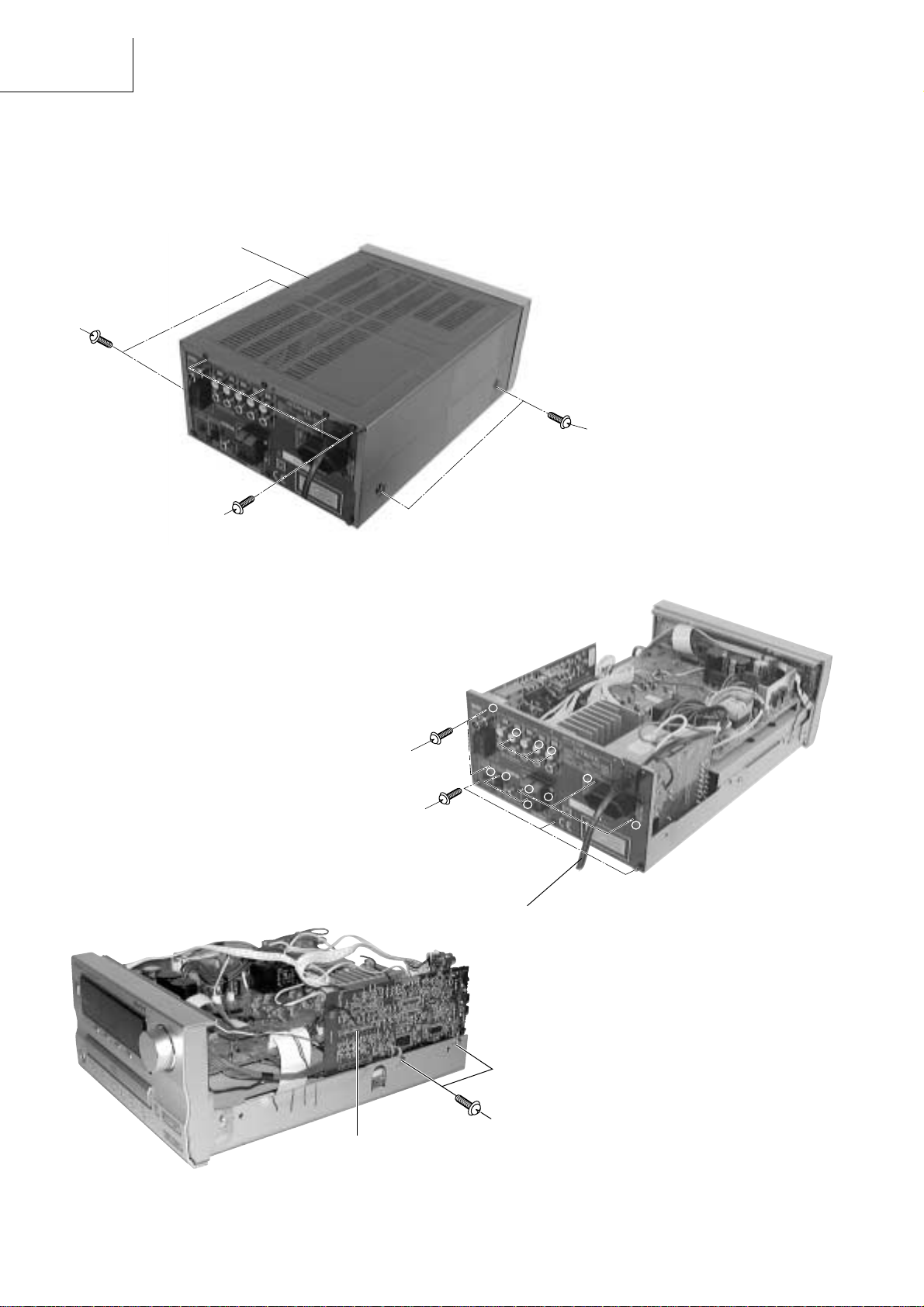
SERVICE POINTS
1. Removal of Top Cover
(1) Remove 4 screws 1 from each side.
(2) Remove 4 screws 2 from the rear plate.
Top cover
1
1
2
Fig. 1
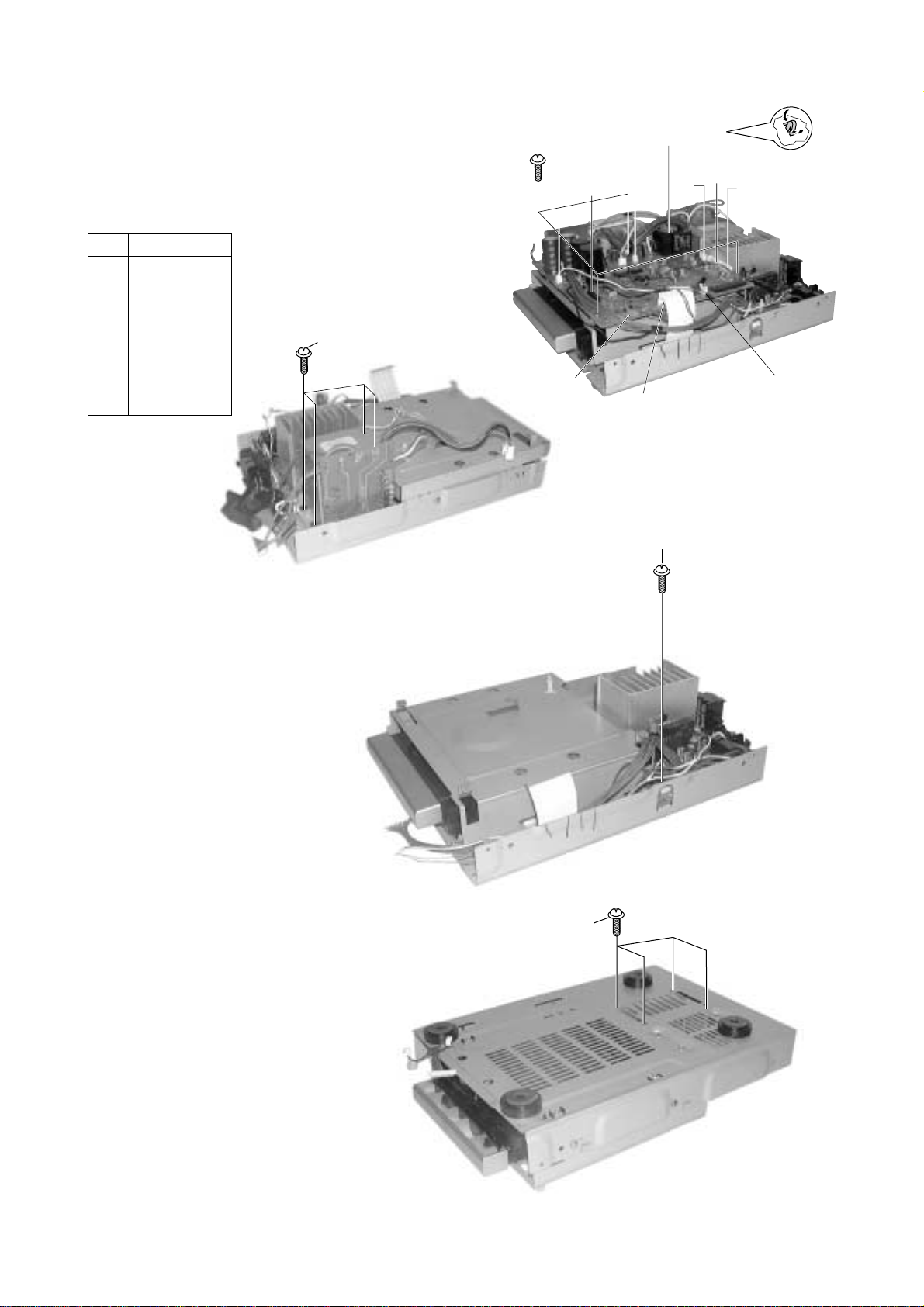
3. Removal of Tuner P.W.B Board
(1) Remove 2 screws 5.
(2) Pull the tuner P.W.B gently to detach from
connector A of the main PCB.
2. Removal of Rear Plate and Power Cord
(1) Remove 11 screws 3 and 4 from the rear plate.
(2) Detach the power cord.
1
3
4
4
2
3
Power cord
5
9
7
8
10
6
11
Fig. 2
Fig. 3
5
Connector A
4
Page 6
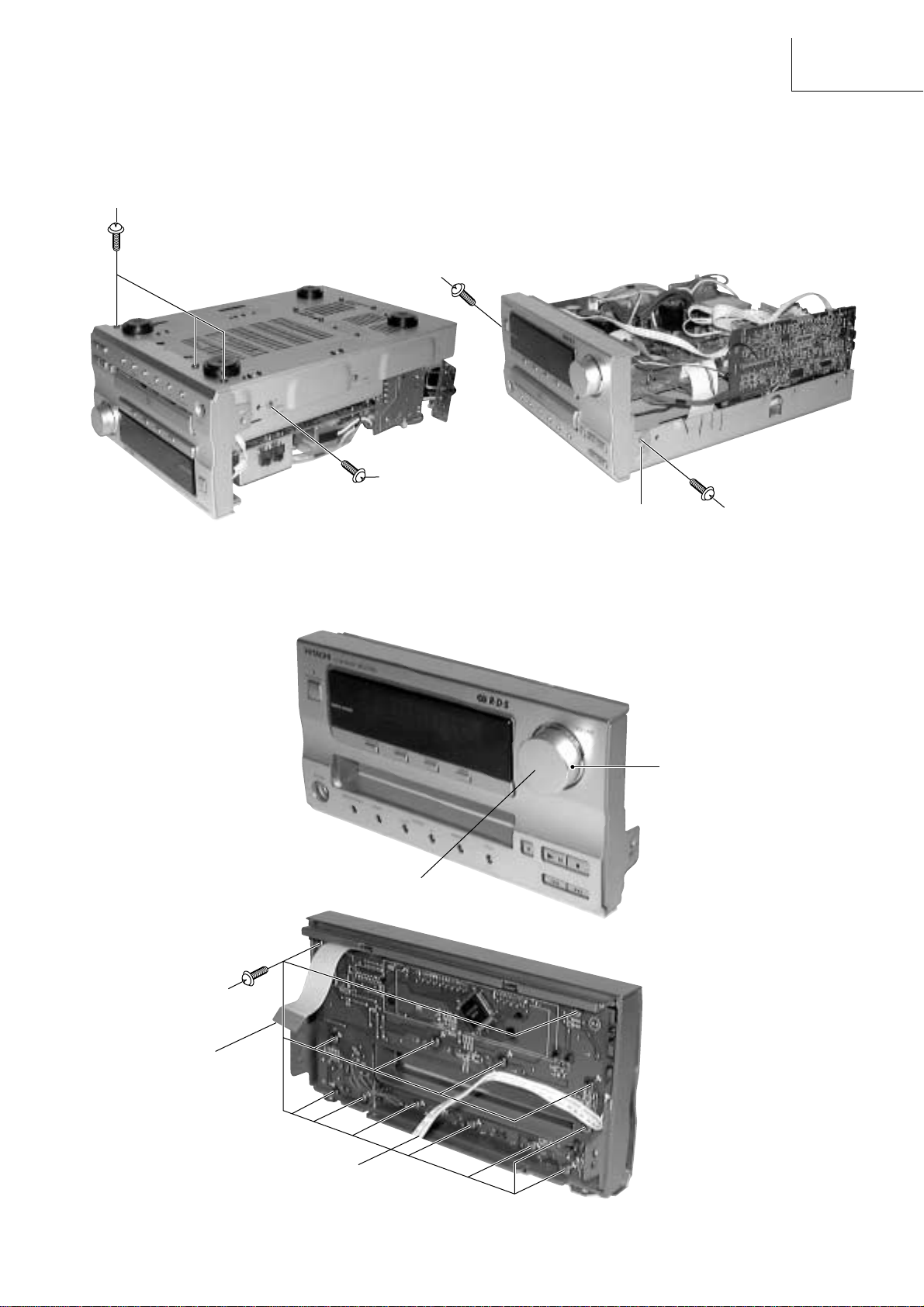
4. Removal of Front Panel
(1) Detach connector B & C (Refer to Fig. 5-2)
(2) Remove 3 screws 6 from base of front panel.
(3) Remove 1 screw 7 from each side and screw 8.
(4) Release the claw of the Inner panel from each side.
6
7
8
Fig. 4-1
Claw
AX-F100
Fig. 4-2
7
5. Removal of Front P.W.B Board
(1) Remove the volume knob to detach the nut.
(2) Remove 13 screws 9.
Fig. 5-1
Volume knob
9
Nut
Connector B
Fig. 5-2
Connector C
5
Page 7
AX-F100
6. Removal of Main P.W.B Board and Power Transformer
(1) Detach the connector D to K.
(2) Remove 4 screws ! from base of the plate and 4
screws ".
(3) Press and push downwards the P.W.B. support.
(4) Gently pull the main P.W.B. upwards and remove
the Power Transformer.
No. CONNECTOR
D CN702
E CN701
F PG301
G PG302
H PG501
I PG601
J CN501
K PG505
L PG602
"
!
K
D
P.W.B. Support
I
J
E
H
G
F
Fig. 6-1
L
7. Removal of Amp P.W.B. Board
(1) Remove 1 screw #.
(2) Remove 4 screws $ from base of chassis.
Fig. 6-2
#
Fig. 7-1
$
6
Fig. 7-2
Page 8
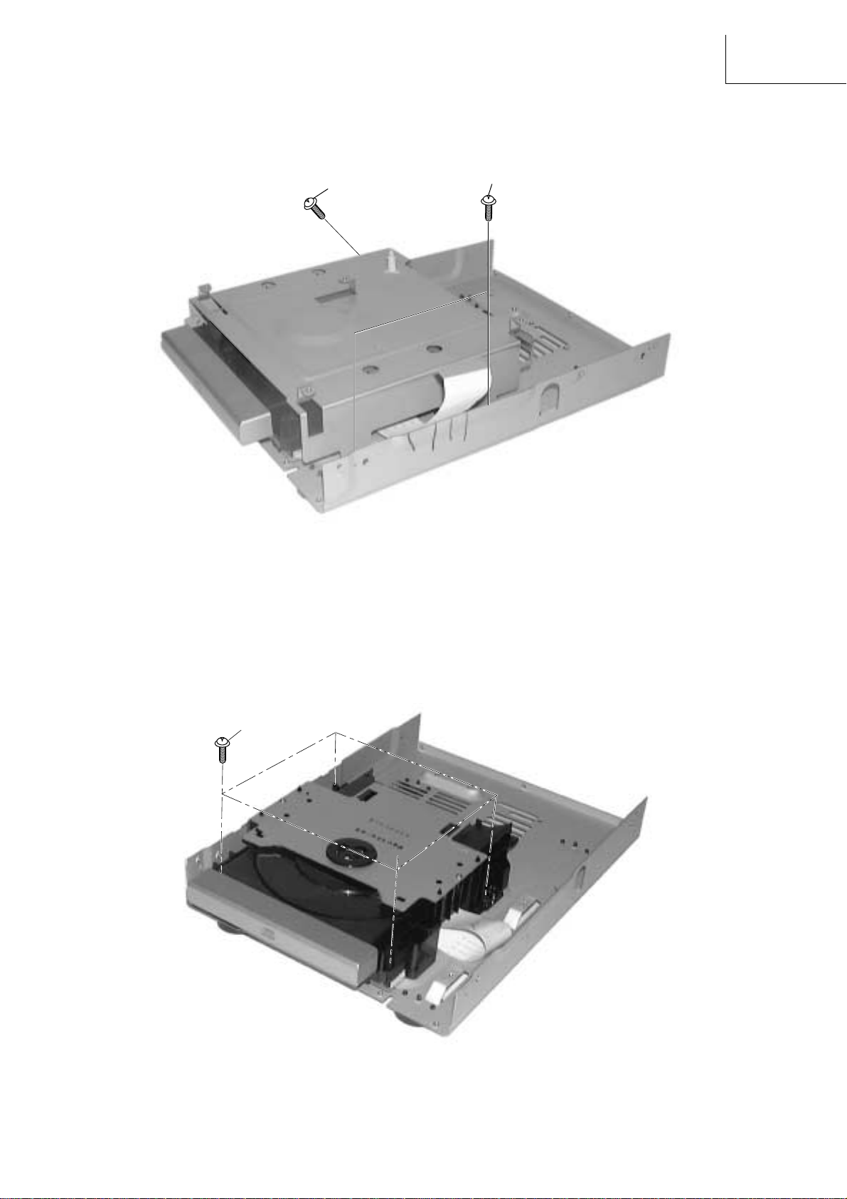
8. Removal of P.W.B. Holder
(1) Remove 3 screws % to detach the P.W.B. Holder.
AX-F100
%
%
Fig. 8
9. Removal of CD Mechanism Assembly
(1) Remove 4 screws & and pull up the CD mechanism.
&
Fig. 9
7
Page 9

AX-F100
WIRING DIAGRAM
FFC CABLE INSERTION
ILLUSTRATION B
ILLUSTRATION A
CN701
CN901A
CN9018 CD MECHA
AC-OUTLET PWB
W11A
W8B
2P PH-SAN CONN
11CN601
CN602
CN505
1
2P MX CONN
BRN
WHT
5P PH-SAN CONN
PG503
1
CN501
RED
W9B
RED
GRY
AMP PWB
I/0 PWB
CN302 1 CN301 1
W7A W6A
FOR W/WUN
VOL-SEL PWB
3P PH-SAN CONN
W3B
W2B
BLK RED YEL
W1B
5001
11P PH-SAN CONN
CN502
CN504A
3P TXL CONN
TH PWB
AC1
3P DA-DA CONN
CN504B
10P PH-SAN CONN
8P PH-SAN CONN
PG302 1 PG301 1
PG501
1
W5AW9A
RED
PG001
1
CN201A
TU PWB
18P B-B
TO CD MECHA
REFER TO ILLUSTRATION B FOR DETAILS
CA701(30P FFC CABLE)
CN201B
1
1
PG602
CN701 1
MAIN PWB
WHT
1
1
RED
W4A
YEL
RED
W2A
W3A
BRN
W11B
GRY
RED
TRANS PWB
PG601
W8A
(FOR UC/E/EBS ONLY)
ORG
W1A
BLK
ORG
W4B
W7B
W6B
3P MX CONN
W5B
RED
CN003
PG003
PG002
CN002
2P TXL CON
2P MX CONN
1
REDBLUBLKBLURED
CN702
5P VH CONN
1
CN901A
1
PG502
2P PH-SAN CONN
PG505
1
11P PH-SAN CONN
CA901 (18P FFC CABLE)
REFER TO ILLUSTRATION A FOR DETAILS
CN901B
FL PWB
CN503
5P PH-SAN CONN
8
Page 10

PRINTED WIRING BOARD
AX-F100
Soldering SideComponent Side
TU PWB
9
Page 11

AX-F100
Component Side
MAIN PWB
8
Page 12

Soldering Side
AX-F100
MAIN PWB
9
Page 13

AX-F100
Component Side
I/O P.W.B.
FL PWB
AC OUTLET P.W.B.
12
Page 14

Soldering Side
AX-F100
I/O P.W.B.
FL PWB
AC OUTLET P.W.B.
13
Page 15

AX-F100
Component Side
AMP PWB
TH P.W.B.
TRANS P.W.B.
VOL-SEL P.W.B.
14
Page 16

Soldering Side
AX-F100
AMP PWB
TH P.W.B.
TRANS P.W.B.
VOL-SEL P.W.B.
15
Page 17

AX-F100
16
Page 18

CIRCUIT DIAGRAM
MAIN/POWER Circuit
AX-F100
18 17
19
Page 19

AX-F100
CIRCUIT DIAGRAM
—FL DISP. Circuit
21
22 20
Page 20

CIRCUIT DIAGRAM
TUNER Circuit
AX-F100
24
25 23
Page 21

AX-F100
28 26 27
Page 22

BLOCK DIAGRAM (MAIN)
Q309, Q310
LR MUTE
Q307, Q308
L, R MUTE
JK 302
MD OUTMD INAUX
JK 301
TAPE OUTTAPE IN
IC 303 BU4066BCF
TA/MD REC SW
IC501
STK 402-405
POWER AMPLIFIER
Q505
MUTE
JK501
H.PHONE
JK502
MONO
OUT
RY501
SPEAKER
AX-F100
JK503
SP TERMINAL
RELAY
Q305, Q306
L,R MUTE
IC302
BU4066BCF
TA/MD FUNC SW
JK602
OPT
OUT
IC301 LC75342
FUNC SW,
EQUALIZER &
ELECT VOLUME
CONTROL
JK601
SYSTEM
BUS
T203,
T204
19 KHz
LPF
Q105,
Q106, Q107, Q108
FM MPX
AM/FM IF
L,RMUTE
IC601
µ–con
MN101C12GPT
( E & EBS ONLY )
IC201
LA1838
AM RF MIX
CD MECHA
IC603
KIA7045
RESET
IC901
LC75725E
FLD DRIVER
FL901
FL DISPLAY
Q102,
FE101
JK 101
Q103,IFAMP
B.P.F
FM RF
AMP &
OSC MIX
FM ANTAM ANT
IC101
LC72131M
BL1AMRF
PLL
29
IC251
LC72720NM
RDS
IC602
EEPROM
BR9040F
KEY
RE 901
(E/EBS & UC ONLY)
ENCODER
Page 23

AX-F100
BLOCK DIAGRAM (POWER)
F003
F001
AC OUTLET JK001
S001
VOLT AGE
FOR W,WUN ONLY
SELECTOR
Q005
KTA1267
FOR W,WUN ONLY
PT1
POWER
TRANSFORMER
D011
RECT
F002
D012
RECT
SUB
PT001
TRANSFORMER
RECT
D002~D005
FLD
~3.5V
FILAMENT
µ-CON/EEPROM/
IC001
KIA7805
+5V
RESET
IC004
40V
40V
+
-
SUPPLY
-27V
IC501
+23V
POWER
AMPLIFIER
SUPPLY
-23V
SWITCHING
+12V
IC301~303
KIA7812
& TUNER
SUPPLY
IC003
KIA7809
+9V
CD MOTOR
SUPPLY
CD SUPPLY/
IC002
KIA7806
+6V
FLD DRIVER/BUS/
TUNER SUPPLY
FLD
30
Page 24

EXPLODED VIEW (Cabinet Chassis)
• Nos. are reference Nos. of part list
AX-F100
33
48
24
[FOR W, W(UN)]
23
2
FL DISP PWB
26
1
TRANSFORMER
TU PWB
MAIN PWB
34
34
27
35
36
32
30
AMP PWB
2
13
12
12
12
39
37
38
46
28
40
14
11
6
8
10
9
7
15
4
44
16
17
43
42
4
43
42
31
41
45
3
42
41
43
29
25
43
42
41
25
18
19
20
18
22
[FOR E, E(BS)]
22
[FOR W, W(UN)]
47
20
20
20
21
5
41
32 31
Page 25

THE UPDATED PARTS LIST
FOR THIS MODEL IS
AVAILABLE ON ESTA
Page 26

Hitachi, Ltd. Tokyo, Japan
International Sales Division
THE HITACHI ATAGO BUILDING,
No. 15 –12 Nishi Shinbashi, 2 – Chome,
Minato – Ku, Tokyo 105-8430, Japan.
Tel: 03 35022111
HITACHI EUROPE LTD,
Whitebrook Park
Lower Cookham Road
Maidenhead
Berkshire
SL6 8YA
UNITED KINGDOM
Tel: 01628 643000
Fax: 01628 643400
Email: consumer-service@hitachi-eu.com
HITACHI EUROPE GmbH
Munich Office
Dornacher Strasse 3
D-85622 Feldkirchen bei München
GERMANY
Tel: +49-89-991 80-0
Fax: +49-89-991 80-224
Hotline: +49-180-551 25 51 (12ct/min)
Email: HSE-DUS.service@hitachi-eu.com
HITACHI EUROPE srl
Via Tommaso Gulli N.39, 20147
Milano, Italia
ITALY
Tel: +39 02 487861
Tel: +39 02 38073415 Servizio Clienti
Fax: +39 02 48786381/2
Email: customerservice.italy@hitachi-eu.com
HITACHI EUROPE S.A.S
Lyon Office
B.P. 45, 69671 BRON CEDEX
FRANCE
Tel: 04 72 14 29 70
Fax: 04 72 14 29 99
Email: france.consommateur@hitachi-eu.com
HITACH EUROPE AB
Egebækgård
Egebækvej 98
DK-2850 Nærum
DENMARK
Tel: +45 43 43 6050
Fax: +45 43 60 51
Email: csgnor@hitachi-eu.com
Hitachi Europe Ltd
Bergensesteenweg 421
1600 Sint- Pieters-Leeuw
BELGIUM
Tel: +32 2 363 99 01
Fax: +32 2 363 99 00
Email: sofie.van.bom@hitachi-eu.com
www.hitachidigitalmedia.com
HITACHI EUROPE S.A.
364 Kifissias Ave. & 1, Delfon Str.
152 33 Chalandri
Athens
GREECE
Tel: 1-6837200
Fax: 1-6835964
Email: service.hellas@hitachi-eu.com
HITACHI EUROPE S.A.
Gran Via Carlos III, 101- 1
08028 Barcelona
SPAIN
Tel: 93 409 2550
Fax: 93 491 3513
Email: atencion.cliente@hitachi-eu.com
HITACHI Europe AB
Box 77 S-164 94 Kista
SWEDEN
Tel: +46 (0) 8 562 711 00
Fax: +46 (0) 8 562 711 13
Email: csgswe@hitachi-eu.com
HITACHI EUROPE LTD (Norway) AB
STRANDVEIEN 18
1366 Lysaker
NORWAY
Tel: 67 5190 30
Fax: 67 5190 32
Email: csgnor@hitachi-eu.com
HITACHI EUROPE AB
Neopoli / Niemenkatu 73
FIN-15140 Lahti
FINLAND
Tel : +358 3 8858 271
Fax: +358 3 8858 272
Email: csgnor@hitachi-eu.com
HITACHI EUROPE LTD
Na Sychrove 975/8
101 27 Praha 10 – Bohdalec
CZECH REPUBLIC
Tel: +420 267 212 383
Fax: +420 267 212 385
Email: csgnor@hitachi-eu.com
 Loading...