

Page 1

PS 38
Bedienungsanleitung de
Operating instructions en
Mode d’emploi fr
Istruzioni d’uso it
Manual de instrucciones es
Manual de instruções pt
Gebruiksaanwijzing nl
Brugsanvisning da
Bruksanvisning sv
Bruksanvisning no
Käyttöohje fi
Οδηγιες χρησεως el
Használati utasítás hu
Instrukcja obsługi pl
Инструкция по зксплуатации ru
Návod k obsluze cs
Návod na obsluhu sk
Upute za uporabu hr
Navodila za uporabo sl
Ръководство за обслужване bg
Kulllanma Talimatı tr
Lietošanas pamācība lv
Instrukcija lt
Kasutusjuhend et
IНСТРУКЦIЯ З ЕКСПЛУАТАЦIЇ uk
Instrucţiuni de utilizare ro
Printed: 08.07.2013 | Doc-Nr: PUB / 5070400 / 000 / 01
Page 2
M
e
nu
10 9
141312
11
4
6 416158 7
4
N
U
1
2 3
44
5
1
Printed: 08.07.2013 | Doc-Nr: PUB / 5070400 / 000 / 01
Page 3
N
U
1
2
3
2
3
12
13
0cm
3.5cm
PS 38
0cm
9
2
4
6
8
6
10
2
4
6
8
Universalmodus
8
1
2
3
4
5
7
11
Printed: 08.07.2013 | Doc-Nr: PUB / 5070400 / 000 / 01
Page 4
A
A
B
B
4
c
b
a
5
Printed: 08.07.2013 | Doc-Nr: PUB / 5070400 / 000 / 01
Page 5
6
Printed: 08.07.2013 | Doc-Nr: PUB / 5070400 / 000 / 01
Page 6
ORIGINAL OPERATING INSTRUCTIONS
PS 38 ultidetector
It is essential that the operating instructions
are read before the tool is operated for the
first time.
Always keep these operating instructions together with the tool.
Ensure that the operating instructions are
with the tool when it is given to other persons.
Contents Page
1 These numbers refer to the corresponding illustrations. The illustrations can be found on the fold-out cover
pages. Keep these pages open while studying the operating instructions.
In these operating instructions, the designation “the tool”
always refers to the PS 38 Multidetector.
M
1 General information 13
2Description 14
3 Technical data 15
4 Safety instructions 16
5Beforeuse 17
6 Operation 18
7 Care and maintenance 21
8 Troubleshooting 22
9Disposal 22
10 Manufacturer’s warranty 23
11 EC declaration of conformity (original) 23
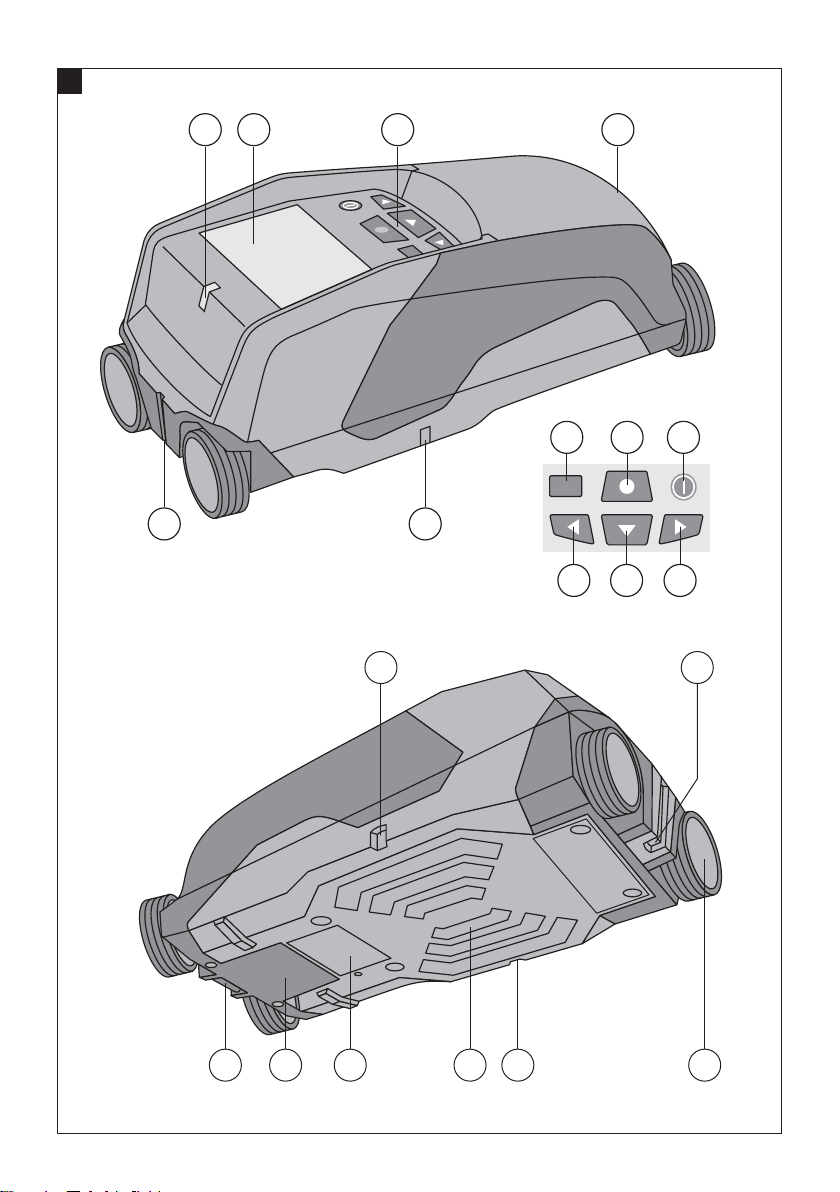
Parts and operating controls 1
Display
@
Control panel
;
Battery compartment
=
Marking notches
%
Status LED (red / green)
&
Sensor area
(
Wheel
)
Wrist strap attachment point
+
On/off button
§
Measure button
/
Menu button
:
“Left” button
·
“Down” button
$
“Right” button
£
Service cover
|
Type identification plate
¡
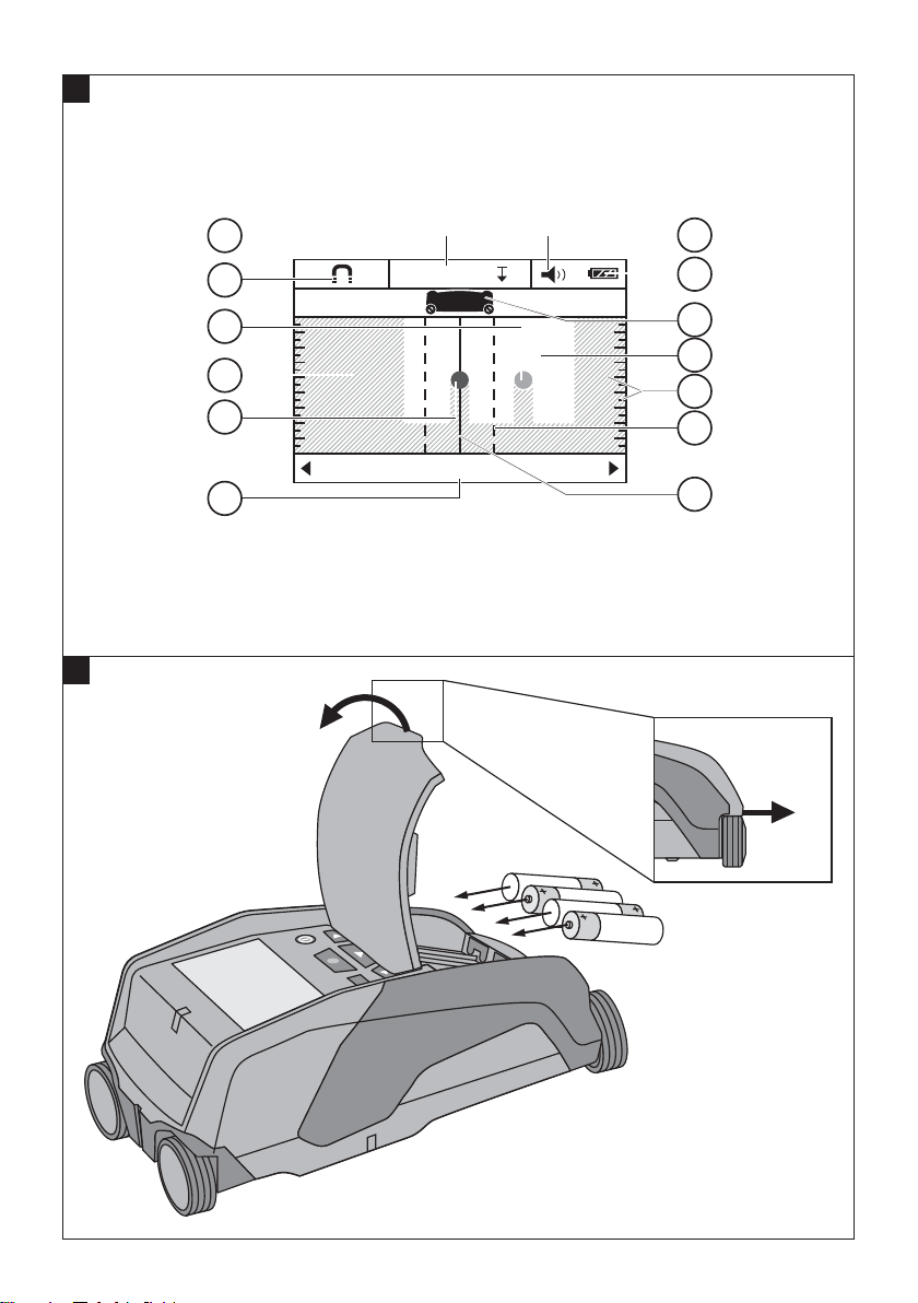
Display 2
Signal tone indicator
@
Battery status indicator
;
Sensor area indicator
=
Already scanned area
%
Scaleshowingapproximatedepthoftheobject
&
Unscanned area
(
Position of outside edge (for marking a detected
)
object at one of the lateral marking notches)
Scanning mode indicator
+
Gray: detected object is outside the sensor area
§
Black: detected object is inside the sensor area
/
The middle line corresponds with the upper mark-
:
ing notch
Approximate depth of the object
·
Object category or live cable indicator
$
en
1 General information
1.1 Safety notices and their meaning
DANGER
Draws attention to imminent danger that will lead to
seriousbodilyinjuryorfatality.
WARNING
Draws attention to a potentially dangerous situation that
could lead to serious personal injury or fatality.
CAUTION
Draws attention to a potentially dangerous situation that
could lead to slight personal injury or damage to the
equipment or other property.
NOTE
Draws attention to an instruction or other useful information.
1.2 Explanation of the pictograms and other
information
Warning signs
General
warning
13
Page 7
Symbols
Location of identification data on the tool
The type designation and serial number can be found on
thetypeidentificationplateonthetool.Makeanoteof
this data in your operating instructions and always refer
to it when making an enquiry to your Hilti representative
or service department.
Type:
en
Read the
operating
instructions
before use.
Return waste
material for
recycling.
Generation: 01
Serial no.:
2 Description
2.1 Use of the product as directed
The PS 38 Multidetector is designed to detect objects such as ferrous metals (rebars), non-ferrous metals (copper and
aluminium), wood beams, plastic pipes, electric cables in dry materials.
Further information and examples of applications can be found at www.hilti.com/detection
The tool and its ancillary equipment may present hazards when used incorrectly by untrained personnel or when used
not as directed.
Observe the information printed in the operating instructions concerning operation, care and maintenance.
Take the influences of the surrounding area into account. Do not use the tool or appliance where there is a risk of fire
or explosion.
Modification of the tool is not permissible.
2.2 Displaying object categories
Symbol Ferrous metal
Symbol Non-ferrous metal
Symbol Plastic / wood
Symbol Live electric cable
Symbol Unknown object
2.3 Detectable objects
- Steel reinforcing bars
- Metal pipes (e.g. steel, copper, aluminium)
- Plastic pipes (e.g. plastic pipes containing water, e.g. floor or wall heating, etc.)
-Cavities
14
Page 8

-Woodbeams
- Electric cables (irrespective of whether the cables are live or not)
- Three-phase electric cables (e.g. for electric cookers)
- Low-voltage cables (e.g. for doorbells or telephones)
2.4 Materials suitable for scanning
- Concrete / steel reinforced concrete
- Masonry (brick, cellular concrete, expanded concrete, pumice concrete, sand-lime block)
- Materials beneath surfaces such as plaster, tiles, wallpaper, parquet, carpet
- Wood, plasterboard / gypsum board
2.5 Scanning limitations
Due to the scanning principle employed, certain unfavorable circumstances may negatively affect the result:
- Multiple layers on walls or floors
- Empty plastic pipes in hollow brick, wood beams in cavities and in drywall partitions
- Objects that run through the wall at an angle
- Metal surfaces and damp areas; under certain circumstances, these may be detected as objects in the material
being scanned
- Cavities in the material being scanned; these may be detected as objects
- Proximity to appliances that emit powerful magnetic or electromagnetic fields, e.g. mobile or cordless phone base
stations and generators
2.6 Items supplied
1 The tool
1 Hand strap
4Batteries
1 Operating instructions
1 Manufacturer’s certificate
1 Soft pouch
1 Set of marking pens
1 Hilti toolbox
en
3 Technical data
Right of technical changes reserved.
NOTE
¹⁾Dependsonscanningmode,thesizeandtypeoftheobjectandonthecondition and type of material to be scanned
(see fig. 5 on the cover pages).
PS 38
Maximum detection range for locating objects ¹⁾ 12 cm (4.7 in)
Location accuracy (to the middle of the object) a ¹⁾ ± 5 mm (± 0.2 in)
Depth measurement accuracy b ¹⁾ ± 10 mm (± 0.4 in)
Minimum distance between two objects c ¹⁾ 4 cm (1.57 in)
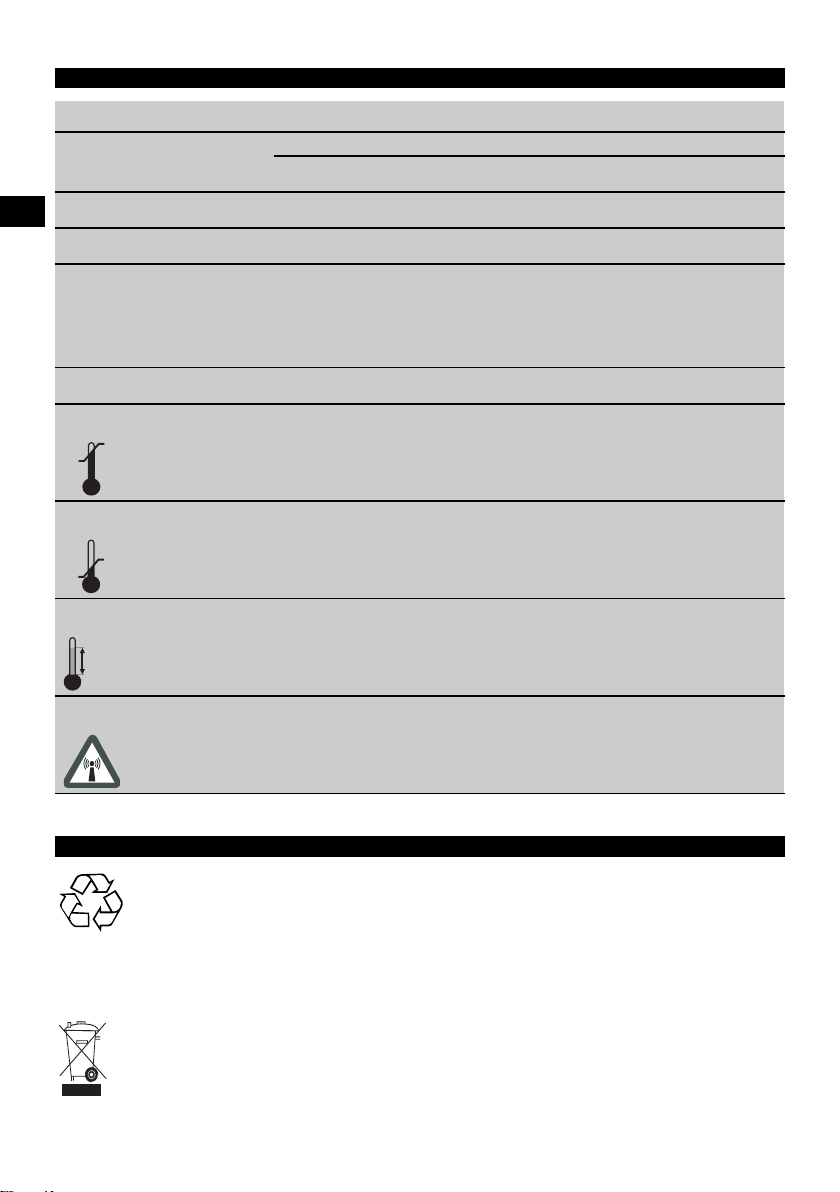
Operating temperature range -10…+50°C (14 °F ... 122 °F)
Storage temperature range -20…+70°C (-4 °F ... 158 °F)
Batteries 4 x 1.5 V LR06 (AA)
Batteries 4 x 1.2 V HR06, KR06 (AA)
Battery life (alkaline batteries) 5 h
Battery life (with 2500 mAh batteries) 7 h
15
Page 9

Protection class IP 54 (protection against dust and water spray)
Weight in accordance with EPTA procedure 01/2003 0.7 kg (1.5 lb)
Dimensions(LxWxH) 195mmx90mmx75mm(7.7inx3.5inx3.0in)
4 Safety instructions
en
In addition to the information relevant to safety given
in each of thesections ofthese operatinginstructions,
the following points must be strictly observed at all
times.
4.1 Basic information concerning safety
a) Keep children away from the tool.
b) Check the display after switching the tool on. The
display should show the Hilti logo and the name of
the tool. The display then shows the current settings
or the settings previously saved.
c) Operation of the tool in the proximity of persons
with a cardiac pacemaker is not permissible.
d) Operation of the tool in the proximity of pregnant
women is not permissible.
e) Rapidly changing detection conditions may lead to
inaccurate readings.
f) Do not use the tool in the proximity of medical
instruments and appliances.
g) Do not drill at positions where the tool has located
an object.
h) The warnings shown in the display must always
be observed.
i) Due to the scanning principle employed, the res-
ults of the scan may be negatively affected by certain ambient conditions. These include, e.g. proximity to appliances that generate powerful magnetic or electromagnetic fields, dampness, construction materials containing metal, aluminium
foil-backed insulation, multiple layers, materials
with cavities or electrically conductive wall coverings or tiles. Accordingly, other sources of information (e.g. plans of the building) should also
be consulted before beginning drilling, sawing or
grinding in the area scanned.
j) Take the influences of the surrounding area into
account. Do not use the tool where there is a risk
of fire or explosion.
k) Make sure that the display area can be easily
read (e.g. do not touch the display area with the
fingers, keep the display area clean).
l) Do not use the tool if it is defective.
m) Always keep the detection area clean.
n) Always check how the tool is set before using it.
o) Operation of the tool in the proximity of military
installations, airports or astronomical facilities is
not permissible unless prior permission has been
obtained.
4.2 Proper organization of the workplace
a) Avoid unfavorable body positions when working
from ladders. Make sure you work from a safe
stance and stay in balance at all times.
b) When the tool is brought into a warm environment
from very cold conditions, or vice-versa, allow it
to become acclimatized before use.
c) Only use the tool within the defined limits.
d) Observe the accident prevention regulations ap-
plicable in your country.
4.3 Electromagnetic compatibility
The tool complies with the requirements of EN 302435.
Accordingly, permission must be obtained prior to operating this tool, for example, in hospitals, atomic power
stations or in the proximity of airports or mobile phone
relay stations.
4.4 General safety instructions
a) Check the condition of the tool before use. If the
tool is found to be damaged, have it repaired at a
Hilti Service Center.
b) Keep the tool clean and dry at all times.
c) Do not apply stickers or adhesive plates at the
sensor area on the underside of the tool. Metal
plates, in particular, will affect scanning results.
d) Take care to ensure that the service cover on the
tool is always securely closed. The service cover
may be opened only at a Hilti Service Center.
e) You must check the accuracy of the tool after it
has been dropped or subjected to other mechanical stresses.
f) Although the tool is designed for the tough con-
ditions of jobsite use, as with other measuring
instruments it should be treated with care.
g) Although the tool is protected against the entry of
moisture,itshouldbewipeddrybeforebeingput
away in its transport container.
h) Check the accuracy of the tool before using it for
detection or measurement.
4.5 Electrical safety
a) Keep the batteries out of reach of children.
b) Remove the batteries from the tool if it is toremain un-
used for some time. The batteries will self-discharge
and may begin to corrode if stored for a long period.
16
Page 10

c) Always replace all batteries at the same time. Use
only batteries of the same capacity and from the
same manufacturer.
d) Do not allow the batteries to overheat and do not
expose them to fire. The batteries may explode or
release toxic substances.
e) Do not charge the batteries.
f) Do not solder the batteries into the tool.
5Beforeuse
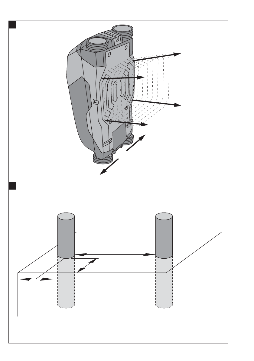
5.1 Inserting the batteries 3
CAUTION
Do not use damaged batteries.
CAUTION
Always replace the complete set of batteries.
CAUTION
Do not mix old and new batteries. Do not mix batteries
of different makes or types.
1. Release the catch on the underside of the tool and
open the battery compartment cover.
2. Insert the batteries in the tool. Close the cover and
check that it engages in the closed position.
NOTE Take care to observe correct polarity (see
symbols in batterycompartment).
The battery status indicator in the display on the tool
shows the charge status of the batteries.
3. Check to ensure that the battery compartment cover
is closed correctly.
5.2 Switching the tool on / off
1. Switch the tool on by pressing the on/off button.
The status LED lights green and the display shows
the start-up screen.
2. When the tool is already switched on, press the
on/off button: The tool switches off.
NOTE If the warning “Change batteries” is shown in
thedisplaythesettingswillbesavedandthetool
then switches itself off automatically.
NOTE If no scan is made or no button is pressed,
the tool will switch itself off automatically after 5
minutes. The switch-off time can be set in menu
mode (see section 5.5.4 “Switch-off time”).
5.3 Changing the scanning mode
The “Left” and “Right” buttons can be used to scroll
through the various scanning modes. By changing the
scanning mode the tool can be adjusted to achieve optimum results on various materials and, where necessary,
detection of undesired objects can be suppressed (e.g.
g) Do not discharge the batteries by short-circuiting.
This may cause them to overheat and present a risk
of personal injury (burns).
h) Do not attempt to open the batteries and do not
subject them to excessive mechanical stress.
4.6 Transport
Always remove the batteries before shipping the tool.
cavities in bricks). The currently active setting is shown
in the lower area of the display.
5.3.1 Universal mode (default setting)
The scanning mode for most applications in solid masonryorconcreteis“Universalmode”.Inthismode,
metal or plastic objects and electric cables are detected.
Cavities in brick or empty plastic pipes with a diameter
of less than 2 cm (0.8 in) will probably not be detected.
The maximum detection depth is 8 cm (3.2 in).
5.3.2 Concrete
The “Concrete” scanning mode is particularly suitable
for use on concrete. In this mode, steel reinforcing bars,
plastic or metal pipes and electric cables are detected.
The maximum detection depth is 12 cm (4.7 in).
“Universal mode” should be selected in order to avoid
scanning errors when the tool is used on thin concrete
walls.
5.3.3 Floor heating
The “Floor heating” scanning modeis particularly suitable
for detecting metal, metal composite and water-filled
plastic pipes or electric cables under a layer of screed.
The maximum detection depth is 8 cm (3.2 in).
NOTE
Empty plastic pipes will not be found.
5.3.4 Drywall
The “Drywall” scanning mode can be used to find wood
beams, metal framing parts, pipes containing water and
electric cables in drywall partitions. The maximum detection depth is 8 cm (3.2 in).
NOTE
Empty plastic pipes will not be found.
5.3.5 Hollow brick
“Hollowbrick”modeissuitableforuseonmasonry
containing a large number of cavities. In this mode, metal
objects, water-filled plastic pipes and live electric cables
will be detected. The maximum detection depth is 8 cm
(3.2 in).
NOTE
Empty plastic pipes and electric cables carrying no electric power will not be detected.
en
17
Page 11
5.4 Changing the display mode
DN
DN
en
DN DN
DN
$PODSFUF
The display mode can be changed in all scanning modes.
This function changes only the display mode, not the
scanning mode.
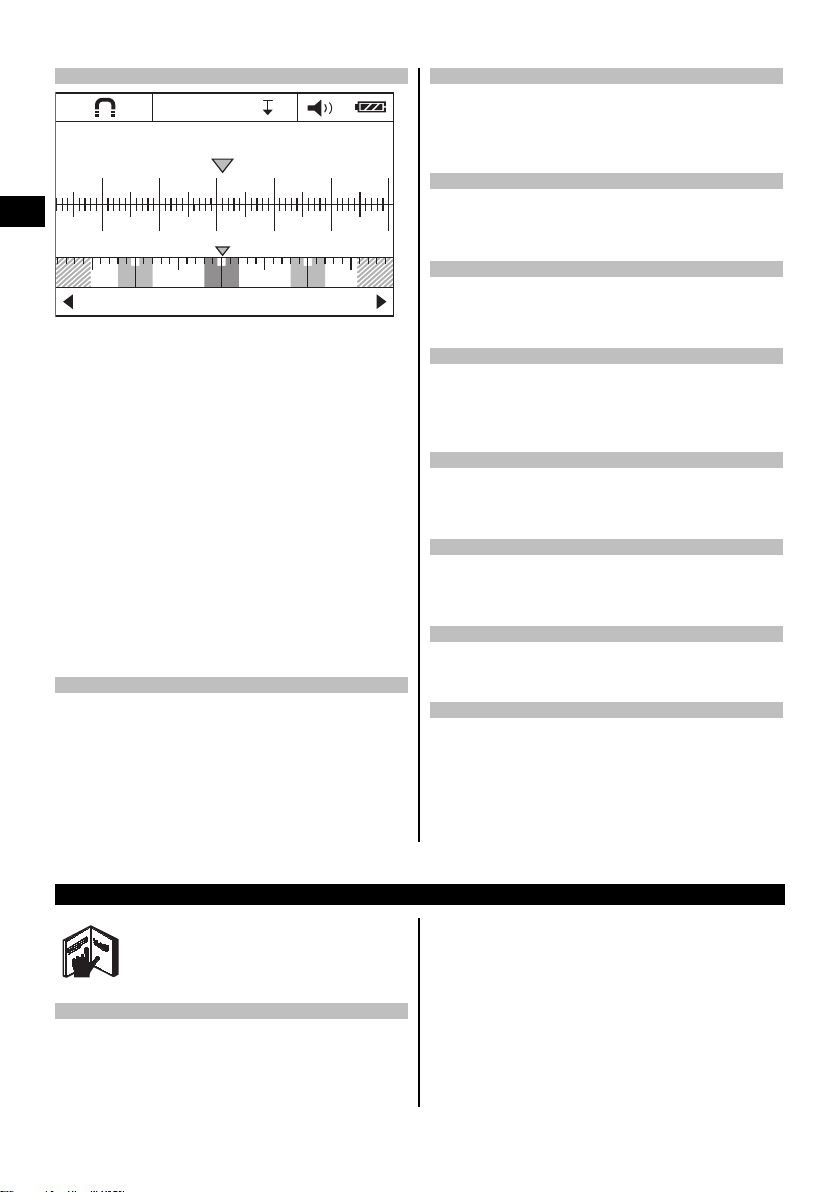
To change from the standard display to distance measurement mode, press the “Left” or “Right” button for
more than 2 seconds. The display mode can be changed
again by pressing one of these buttons.
NOTE
Distance measurement mode can be used to measure
the distance between objects. In the illustration shown,
three equally spaced metal objects have been detected
(see section 6.3.1 “Example showing rebars”).
Thedistancescanned(fromthestartingpointofthescan)
is shown in the display below the approximate depth of
the object, e.g. 20.1 cm (7.9 in), as shown in the example.
The three objects detected, which are each a distance of
10 cm (3.9 in) apart, are shown as small rectangles above
the scanning mode.
5.5 “Settings” menu
To enter the “Settings” menu, press the “Menu” button.
To leave the “Settings” menu, press the “Menu” button
again.
The settings selected up to this point will be saved and
the tool then returns to the standard display screen.
5.5.1 Navigating in the menu
1. To accessthe menu items, press the “Down” button.
The selected menu item is highlighted in gray.
2. Press the “Left” or “Right” button to change the
selected menu item.
5.5.2 Brightness
The brightness of the display can be adjusted in the
“Brightness” menu. The default setting is “Max” (maximum brightness).
5.5.3 Signal tones
In the “Signal tones”menu youcan choose whether or not
an audible signal is emitted when an object is detected.
In the default setting, the signal tone is active.
5.5.4 Cut-off time
The time interval before the tool switches itself off automatically when no scan is made or when no button is
pressed can be set in the “Cut-off time” menu. The
default setting is “5 min.”.
5.5.5 Default mode
The mode to be used as standard after the tool is
switched on can be set in the “Default mode” menu.
“Universal mode” is the default setting.
5.5.6 Language
Thelanguageusedinthedisplayandinthemenuscan
be changed in the “Language” menu. “English” is the
default setting.
5.5.7 Units
Use this menu to select metric or imperial units of measure. The default setting is “metric”.
5.6 “Extended settings” menu
To access the “Extended settings” menu, press the
“Menu” button and the “On/off” button simultaneously
while the tool is switched off.
To leave the menu, press the “Measure” button.
NOTE
The submenus can be used to display information about
the tool or to restore the default settings.
6Operation
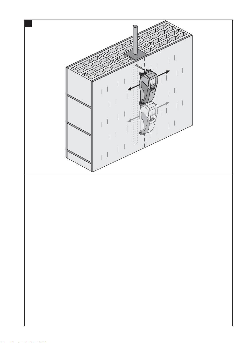
6.1 Using the tool 4
The tool scans in direction “A” to the depth indicated
in the display. Scanning takes place only while the tool
is being moved in direction “B” and so long as the
tool is moved a distance of at least 10 cm (3.9 in).
Always move the tool in a straight line over the area to
18
be scanned, applying light and even pressure so that
the wheels remain securely in contact with the surface.
Objects that differ from the material being scanned will be
detected. The display shows the position of the object,
its approximate depth and, when possible, the object
category. Optimum results will be achieved when the
scan has a length of at least 40 cm (15.7 in) and the tool
is moved slowly over the surface to be scanned. Due
to the operating principle employed, the upper edges of
objects that lie transversely to the scanning direction will
be reliably detected.
Page 12
Accordingly, always scan the area crosswise (i.e. in two
scans perpendicular to each other) in order to avoid errors
due to scanning along the length of an object.
NOTE
When several objects are positioned one above the other
in the material being scanned, the object closest to the
surface will be shown in the display. The image of the
object shown in the display may differ from the actual
characteristics of the object concerned. In particular, very
thin objects will be shown thicker than they actually are.
Large, cylindrical objects (e.g. plastic objects or water
pipes) shown in the display may appear narrower than
they actually are.
6.2 Scanning
1. Switch the tool on.
The display shows the standard screen.
Select the scanning mode that suits the material to
be scanned.
2. Place the tool on the surface to be scanned and
move it in the required direction (see section 6.1
“Using the tool”).
The result of the scan will be shown in the display
after the tool has been moved a distance of at least
10 cm (3.9 in).
3. In order to obtain correct results, move the tool
slowlyovertheareatobescanned.
NOTE If the tool is lifted away from the surface
while making the scan, the most recent reading is
shown in the display. The word “Hold” appears in
the sensor area of the display. The scan restarts
when the tool is brought back into contact with
surface and moved again or the “Measure” button
is pressed.
NOTE The approximate depth and the object material category shown in the display refer to the object
shown in black in the sensor area of the screen.
The status LED lights red when an object is within
the sensor area and lights green when no object
is detected. When the status LED blinks red, a live
cable is very probably within the sensor area.
If an object is present below the sensor it is shown
inthesensorareaofthedisplay.Dependingon
the size and depth of the object detected, the object category may also be shown. The approximate
depth to the upper edge of the object detected is
shown in the status line or can be read from the
scaleatthesideofthedisplay.
6.2.1 Locating objects
$
en
3.5 cm
%
3.5 cm
1. A single scan of the area is sufficient for initial
location of an object.
2. If no object is found, repeat the scan at right angles
to the direction of the original scan (see section. 6.1
“Using the tool”).
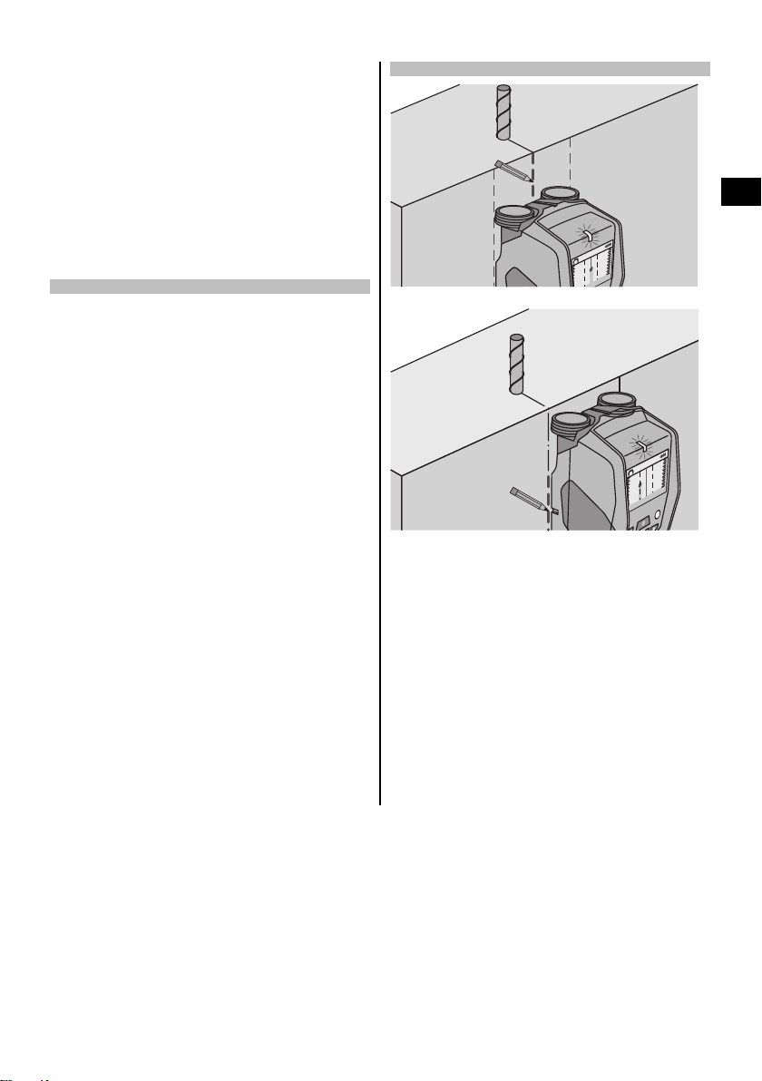
3. If you wish to locate an object exactly and mark
its position, simply move the tool in the reverse
direction back across the area already scanned.
4. If an object appearsin the displayimmediately below
the centerline, as shown in illustration A, the position
of the object can be marked on the surface at the
upper marking notch.
NOTE However, this mark will be accurate only
when the object runs exactly perpendicular to the
direction of scan as the sensor area lies slightly
below the marking notch.
19
Page 13
5. To mark the position more exactly, move the tool to
the left or right until the object detected is shown at
the edge of the display.
6. Mark the position of the detected object by making
a mark beside the right or left marking notch (see
illustration B).
NOTE The object detected lies at the point of intersection of the upper and side marking notches.
en
6.3 Examples of scan results
NOTE
In the following examples, the signal tone is switched on.
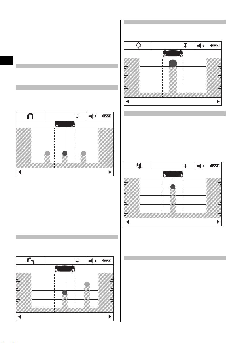
6.3.1 Steel reinforcing bars
Asteelobject,e.g.asteelrebar,ispresentinthesensor
area. To the left and right of this are other objects which
areoutsidethesensorarea.Thedepthoftheobjectis
approx. 8 cm (3.1 in). The tool emits a signal tone.
DN
DN
14
$PODSFUF
NOTE
Best scanning results will be obtained when the tool
is moved at right angles to the longitudinal rebars, as
described above. Mark the positions of the rebars found
and then shift the tool to the adjoining are above or below
and repeat the scan in order to verify the position of the
rebars and the direction in which they run. To locate the
transverse rebars, pivot the tool through 90° and scan
between the already detected longitudinal rebars in order
to avoid scanning along a longitudinal rebar.
6.3.2 Copper pipes
A non-ferrous metal object, e.g. a copper pipe, is within
the sensor area. It lies at a depth of approx. 4 cm (1.6 in).
The tool emits a signal tone.
DN
DN
14
6OJWFSTBM
DN
DN
6.3.3 Plastic or wooden objects
A non-metallic object is within the sensor area. The object
is made of plastic or wood (or is a cavity) and lies close
to the surface. The tool emits a signal tone.
DN
DN
14
DN
%SZXBMM
6.3.4 Live electric cables
NOTE
Depending on the size and depth of the object, it is not
always possible to determine without doubt whether it is
live (i.e. carrying electricity).
NOTE
When scanning, do not lay your hands on the surface of
the material.
DN
DN
14
DN
6OJWFSTBM
A live metallic object, e.g. an electric cable, is within the
sensorarea.Itliesatadepthofapprox.1.5cm(0.6in).
The tool emits a warning signal tone for “live cables” as
soon as the electric cable is detected by the sensor.
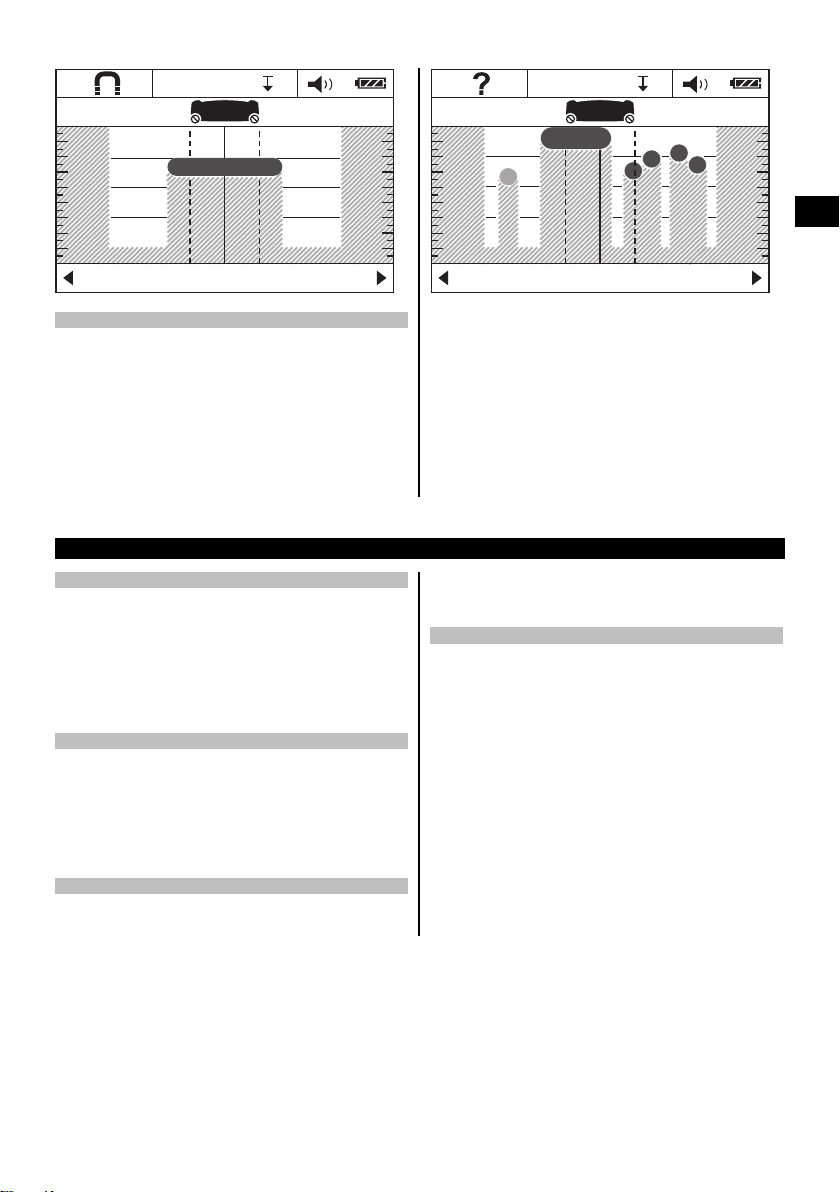
6.3.5 Objects with a large surface area
A metal object with a large surface area, e.g. a metal
plate, is within the sensor area. It lies at a depth of
approx. 2 cm (0.8 in). The tool emits a signal tone.
20
Page 14
DN
DN
14
DN
DN
DN
14
DN
6OJWFSTBM
6.3.6 Unclear signals
If a large number of objects are indicated in the standard
display area, there can be two reasons for this.
1. The wall probably contains a large number of cavities
(hollow brick).
7 Care and maintenance
7.1 Cleaning and drying
1. Use onlya clean,soft clothfor cleaning.If necessary,
moisten the cloth slightly with pure alcohol or a little
water.
NOTE Do not use any other liquids as these may
damage the plastic components.
2. The temperaturelimits forstorage of your equipment
must be observed, especially in winter / summer.
7.2 Storage
Put the tool into storage only when dry. Please observe
the applicable temperature limits when storing the tool.
Check the accuracy of the equipment before it is used
after a long period of storage.
Remove the batteries from the tool before storing it for a
long period. Leaking batteries may damage the tool.
7.3 Transport
Use the Hilti toolbox or equivalent packagingwhen transporting the tool.
6OJWFSTBM
Switch to “Hollow brick” mode. Most of the cavities will
then no longer be shown in the display.
If too many objects are still shown, several scans must be
made at different heights and the position of the objects
detected marked on the wall.
Offset marks tend to indicate cavities while marks in a
line tend to indicate an object.
2. The scan has been made longitudinally, i.e. along the
length of an object. In this case, move the tool up or
down and repeat the scan (see fig. 6 on the cover pages).
CAUTION
Always remove the batteries before shipping the tool.
7.4 Hilti Calibration Service
We recommend that the tool is checked by the Hilti Calibration Service at regular intervals in order to verify its
reliability in accordance with standards and legal requirements.
Use can be made of the Hilti Calibration Service at any
time, but checking at least once a year is recommended.
The Calibration Service provides confirmation that the
tool is in conformance, on the day it is tested, with the
specifications given in the operating instructions.
After checking, acalibration sticker applied tothe tool and
a calibration certificateprovide writtenverification that the
tool is operating in accordance with the manufacturer’s
specification.
Calibration certificates are always required by companies
certified according to ISO 900x.
Your local Hilti Center or representative will be pleased
to provide further information.
en
21
Page 15
8 Troubleshooting
Fault Possible cause Remedy
The tool can’t be switched on. The batteries are exhausted. Replace the batteries.
Incorrect battery polarity. Insert the batteries correctly and
The tool is switched on but
en
doesn’t react.
The tool is too cold or too hot. The tool is too cold or too hot. Wait until it is within the permissible
“Slipping wheel” is shown in the
display.
“Too fast” is shown in the display.
“Out of temperature range” is
shown in the display.
System error. Remove and reinsert the batteries.
A wheel lost contact with the wall. Press the “Measure” button. Take
The tool was moved too quickly. Press the “Measure” button. Move
Temperature above permissible
range.
close the battery compartment cover.
temperature range.
care to ensure that the wheels remain
in contact with the surface when
moving the tool. On uneven surfaces,
place a sheet of thin cardboard
between the wheels and the wall.
the tool slowly over the wall.
Wait until within the permissible tem-
perature range.
“Out of temperature range” is
shown in the display.
The display shows “Tool temperature”
“Strong radio signal detected”
is shown in the display.
Temperature below permissible
range.
The temperature inside the tool has
changed too quickly.
Interference caused by radio signal.
The tool switches itself off automatically.
Wait until within the permissible temperature range.
Switch the tool on again.
If possible, eliminate the radio signal
(e.g. WLAN, UMTS, aircraft radar,
transmittermastormicrowave
device) and switch the tool back on.
9 Disposal
Most of the materials from which Hilti tools or appliances are manufactured can be recycled. The materials must be
correctly separated before they can be recycled. In many countries, Hilti has already made arrangements for taking
back old tools or appliances for recycling. Ask Hilti Customer Service or your Hilti representative for further information.
For EC countries only
Do not dispose of electrical appliances together with household waste.
In observance of the European Directive on waste electrical and electronic equipment and its imple-
mentation in accordance with national law, electrical appliances that have reached the end of their life
must be collected separately and returned to an environmentally compatible recycling facility.
22
Page 16
10 Manufacturer’s warranty
Hilti warrants that the tool supplied is free of defects in
materialandworkmanship.Thiswarrantyisvalidsolong
as the tool is operated and handled correctly, cleaned
and serviced properly and in accordance with the Hilti
Operating Instructions, and the technical system is maintained. This means that only original Hilti consumables,
components and spare parts may be used in the tool.
This warranty provides the free-of-charge repair or replacement of defective parts only over the entire lifespan
of the tool. Parts requiring repair or replacement as a
result of normal wear and tear are not covered by this
warranty.
11 EC declaration of conformity (original)
Designation: Multidetector
Type: PS 38
Generation: 01
Year of design: 2009
We declare, on our sole responsibility, that this product
complies with the following directives and standards:
2011/65/EU, 2006/95/EC, 2004/108/EC, 1999/5/EC,
EN ISO 12100, EN 302435-1, EN 302435-2.
Additional claims are excluded, unless stringent national rules prohibit such exclusion. In particular, Hilti
is not obligated for direct, indirect, incidental or consequential damages, losses or expenses in connection with, or by reason of, the use of, or inability to
use the tool for any purpose. Implied warranties of
merchantability or fitness for a particular purpose are
specifically excluded.
For repair or replacement, send the tool or related parts
immediately upon discovery of the defect to the address
of the local Hilti marketing organization provided.
This constitutes Hilti’s entire obligation with regard to
warranty and supersedes all prior or contemporaneous
comments and oral or written agreements concerning
warranties.
Hilti Corporation, Feldkircherstrasse 100,
FL‑9494 Schaan
Paolo Luccini Matthias Gillner
Head of BA Quality and Process Management
Business Area Electric Tools & Accessories
01/2012 01/2012
Executive Vice President
Business Area Electric
Tools & Accessories
en
Technical documentation filed at:
Hilti Entwicklungsgesellschaft mbH
Zulassung Elektrowerkzeuge
Hiltistrasse 6
86916 Kaufering
Deutschland
23
Page 17

12. FCC statement (US only)
-CAUTION-
This equipment has been tested and found to comply
with the limits for a class Bdigital device, pursuant to
part 15 of the FCC rules. These limits are designed to
providereasonable protectionagainst harmful interferencein a residential installation. This equipmentgener-
en
ates, uses, and canradiate radiofrequency energy and,
if not installed and used in accordance with the instructions, may cause harmful interference to radio communications.
However, there isno guarantee that interferencewill not
occurin a particular installation. Ifthis equipmentdoes
causeharmful interference toradio or televisionreception, whichcan bedeterminedby turning the equipment
on and off,the user is encouraged totry to correct the
interference byone ormore ofthe following measures:
• Re-orient or re-locate the receiving antenna.
• Increase the distance between the equipment and
receiver.
• Connect theequipment toan outleton a circuit differ-
ent from that to whichthe receiver is connected.
• Consult the dealer oran experienced TV/radio techni-
cian for assistance.
-NOTE-
Changes or modifications not expressly approved by
thepartyresponsible for compliancecouldvoidtheuser’s
authority to operate theequipment.
This device complies with part 15 of the FCC Rules.
Operation is subject to the following twoconditions:
1) this device may not cause harmful interference,
and
2) thisdevice must acceptany interferencereceived,
including interference that may cause undesired
operation.
For US customers:
Operation of thisdeviceis restricted tolaw enforcement,
fire and rescue officials, scientific research institutes,
commercial mining companies, construction companies and private parties operating on behalf of these
groups. Operation byany other party is aviolation of47
U.S.C. § 301 and could subject the operator to serious
legal penalties.
Coordination Requirements
(a) UWB imaging systems require coordination through
theFCCbeforetheequipmentmay be used. Theoperatorshallcomplywith any constraintson equipment
usage resulting from this coordination.
(b) The users of UWB imaging devices shall supply
detailedoperationalareas to theFCC Office ofEngi-
neering and Technology who shall coordinate this
information with the Federal Government through
the National Telecommunications and Information
Administration. Theinformation provided by the UWB
operatorshall include the name, address and other
pertinent contact information of the user, thedesired
geographicalarea of operation,and the FCC IDnumberand other nomenclatureof the UWB device. This
materialshall be submittedto the following address:
Frequency Coordination Branch, OET
FederalCommunicationsCommission
445 12th Street, SW
Washington, D.C. 20554
ATTN: UWBCoordination
(d) Users of authorized, coordinated UWB systems may
transferthem to other qualified users and to different locations upon coordination of change of ownership or location tothe FCC andcoordination with
existingauthorized operations.
(e) TheNTIA/FCC coordinationreport shall include any
needed constraintsthat apply today-to-day operations.Suchconstraints couldspecifyprohibitedareas
of operations or areas locatednear authorized radio
stationsfor which additionalcoordinationis required
before operation of the UWB equipment.If additional
local coordination is required, a local coordination
contactwill beprovided. Ground PenetratingRadar
Coordination Notice And Equipment Registration.
Note: This form is only for Domestic UnitedStates
users.Failure to dothis isa violation ofFederal law.
1. Date:
2. Company name:
3. Address:
4. Contact Information [contact name andphone
number]:
5. Area Of Operation [state(s)]:
6. Equipment Identification
Brand Name: PS 38
FCC-ID:SDL-PS38R01
7. Receipt DateOf Equipment:
Fax this formto the FCC at:202-418-1944 or
mail to:
Frequency Coordination Branch, OET
FederalCommunicationsCommission
445 12th Street, SW
Washington, D.C. 20554
ATTN: UWBCoordination
Do notsend thisinformation to Hilti Corporation.
Page 18

13. IC statement (for Canada only)
This device complies with therequirements defined
in RSS-220in conjunctionwith RSS-Gen of IC.
Operation is subjectto the following two conditions:
1) this device may not cause harmful interference,
and
2) thisdevice must acceptany interferencereceived,
including interference that may cause undesired
operation.
For Canadian customers:
Thisdevice shall be operatedonly wheredirectedto the
ground or wall, and isin contactwith the groundor wall
surface.This deviceshall be operatedonlyby law enforcement agencies, scientific research institutes, commercial mining companies, construction companies, and
emergency rescue or fire-fightingorganizations.
en
Page 19

*419205*
419205
Hilti Corporation
LI-9494 Schaan
Tel.:+423 /234 2111
Fax:+423 /234 29 65
www.hilti.com
Hilti = registered trademark of Hilti Corp., Schaan
W 3767 | 0313 | 10-Pos. 1 | 1
Printed in Germany © 2013
Right of technical and programme changes reserved S. E. & O
.
419205 / A2
Printed: 08.07.2013 | Doc-Nr: PUB / 5070400 / 000 / 01
 Loading...