

Page 1

PS 250 /
PS 200 S
Operating instructions en
Mode d’emploi fr
Manual de instrucciones es
Manual de instruções pt
Printed: 10.12.2013 | Doc-Nr: PUB / 5135501 / 000 / 01
Page 2
1
PS 200 Ferroscan
2.
PSA 93
Green
Red
Printed: 10.12.2013 | Doc-Nr: PUB / 5135501 / 000 / 01
Page 3
2
0,
PS 200 Ferroscan
3
PS 200 Ferroscan
4
0,
Printed: 10.12.2013 | Doc-Nr: PUB / 5135501 / 000 / 01
Page 4
ORIGINAL OPERATING INSTRUCTIONS
PS 250 ferroscan system
PS 200 S ferroscan
en
It is essential that the operating instructions
are read before the tool is operated for the
first time.
Always keep these operating instructions together with the tool.
Ensure that the operating instructions are
with the tool when it is given to other persons.
Contents Page
1 General information 1
2Description 2
3 Items supplied, accessories, spare parts 3
4 Technical data 7
5 Safety instructions 10
6Beforeuse 11
7 Operation 11
8 Care and maintenance 28
9 Troubleshooting 29
10 Disposal 31
11 Manufacturer’s warranty 32
12 FCC statement / IC statement 32
1 These numbers refer to the corresponding illustrations. The illustrations can be found on the fold-out cover
pages. Keep these pages open while studying the operating instructions.
In these operating instructions, the designation “the tool”
always refers to PS 200 S Ferroscan. The designation
“PS 250 Ferroscan system” applies to the whole system
consisting of the PS 200 S scanner, PSA 100 monitor and
PROFIS Ferroscan PC software for data evaluation. The
designation “PS 200 S Ferroscan”, on the other hand,
appliesonlytothescanner.
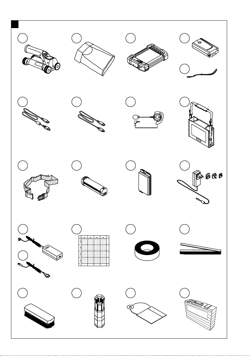
Components 1
PS 200 S scanner
@
PSA 60 soft pouch
;
PSA 100 monitor
=
PSA 55 infrared adapter
%
PSA 63 hand strap
&
PSA 92 USB data cable
(
PUA 95 Micro USB data cable
)
PSA 93 headset with microphone
+
PSA 64 soft pouch
§
PSA 62 carrying strap
/
PSA 80 battery pack
:
PSA 82 battery pack
·
PUA 81 AC adapter
$
PUA 80 charger
£
Supply cord
|
PSA 10/11 reference grid set
¡
PUA 90 adhesive tape
Q
Folding rule
W
PSA 70 brush
E
PUA70markingpenset
R
PROFIS Ferroscan software
T
PS 250 toolbox
Z
1 General information
1.1 Safety notices and their meaning
DANGER
Draws attention to imminent danger that will lead to
seriousbodilyinjuryorfatality.
WARNING
Draws attention to a potentially dangerous situation that
could lead to serious personal injury or fatality.
CAUTION
Draws attention to a potentially dangerous situation that
could lead to slight personal injury or damage to the
equipment or other property.
NOTE
Draws attention to an instruction or other useful information.
1.2 Explanation of the pictograms and other
information
Warning signs
General
warning
Warning:
electricity
Warning:
caustic
substances
1
Page 5
Symbols
Location of identification data on the tool
The type designation and serial number can be found on
thetypeidentificationplateonthetool.Makeanoteof
this data in your operating instructions and always refer
to it when making an enquiry to your Hilti representative
or service department.
Type:
en
Read the
operating
instructions
before use.
Return waste
material for
recycling.
Generation: 02
Serial no.:
2 Description
2.1 Use of the product as directed
The tool is intended to be used for locating reinforcing bars in concrete, measuring depth of concrete cover and
estimating the diameter of the bars in the uppermost layer in accordance with the specifications detailed in the
technical data provided in these operating instructions.
The tool is designed for professional use and may be operated, serviced and maintained only by trained, authorized
personnel. This personnel must be informed of any special hazards that may be encountered. The tool and its ancillary
equipment may present hazards when used incorrectly by untrained personnel or when used not as directed.
Observe the information printed in the operating instructions concerning operation, care and maintenance.
Take the influences of the surrounding area into account. Do not use the tool or appliance where there is a risk of fire
or explosion.
Modification of the tool or tampering with its parts is not permissible.
2.2 PSA 55 infrared adapter
The PSA 55 infrared adapter is used to store scans before they are subsequently transferred to a computer. The
adapter has a storage capacity of approx. 100 scans.
2.3 Applications
The tool can be used for various non-destructive detection applications on steel-reinforced concrete structures (e.g.
locating reinforcing bars in the uppermost layers, measuring depth of concrete cover and estimating the diameter
of the bars detected). The scanning mode used depends on the application. These fall broadly into the following
categories:
Application
Scanning mode
Avoiding damage to reinforcing bars when drilling or core drilling Quickscan detection, Imagescan or
Blockscan
Determining the position / number and diameter of bars for load-
Imagescan
bearing capacity checks or depth of cover measurements
Determining depth of concrete cover over large areas Quickscan recording
2.4 Using the system
The system functions by running the scanner directly over the surface of the structure. The data collected is stored in
the scanner until it can be transferred to the monitor. The monitor is used for storing large amounts of data and for
viewing the scans. It can also be used for on-the-spot evaluation of scans. The data can also be downloaded to a
PC. The PC software offers advanced evaluation options, data archiving functions and the ability to quickly print out
complete reports.
2.5 Quickscan detection
The scanner is moved across the surface at right angles to the reinforcing bars. The position and approximate depth
of the reinforcing bars can be determined and marked right away on the surface of the concrete.
2
Page 6

2.6 Quickscan detection with accurate depth measurement
Before scanning, the operator is required to enter values for the diameter of the reinforcing bars and the spacing
between the bars. The scan is then carried out as described for Quickscan detection.
2.7 Quickscan recording
Data is recorded automatically as the scanner is moved over the surface of the concrete. This data is subsequently
transferred to the monitor where it can be evaluated and the average depth of cover determined. If the data is
downloaded to a PC, the information can be evaluated, archived and a report printed. Further evaluation options
allow Quickscan recordings to be imported and evaluated automatically, statistical evaluations prepared and scans
displayed in the form of large-area evaluations.
2.8 Imagescan
A reference grid is attached at the area of interest using the adhesive tape supplied. After selecting the Imagescan
mode with the scanner, the rows and columns of the grid are scanned following the instructions on the screen. The
data is transferred to the monitor where the image can be viewed and evaluated. The position of the reinforcing bars
relative to the concrete surface is indicated. Bar diameter can be estimated and bar depth determined. If the data is
downloaded to the PC application, this information can be evaluated as on the monitor, with the additional advantage
of allowing a series of points to be recorded along with associated depth and diameter, and the data saved for
future use. Reports can also be printed. Further evaluation options allow Imagescans to be imported and evaluated
automatically, statistical evaluations prepared and scans displayed in the form of large-area evaluations.
2.9 Blockscan
A reference grid is attached at the area of interest using the adhesive tape supplied. After selecting Blockscan mode,
the user is prompted to select the first area to scan. An Imagescan is then made. After completing the Imagescan, the
user is prompted to select the next area to scan. This should be adjacent to the previous area. Attach the grid and then
scan as before. This procedure can be repeated for up to 3 x 3 Imagescans. The data is transferred to the monitor. The
Imagescans are automatically stitched together to form a larger image. The reinforcement layout can then be viewed
over the whole area. Individual Imagescans can be selected for evaluation by “zooming in”. If the data is downloaded
to the PC application, this information can be evaluated as on the monitor, with the additional advantage of allowing a
series of points to be recorded along with associated depth and diameter, andthedatasavedforfutureuse.Reports
can also be printed.
en
3 Items supplied, accessories, spare parts
3.1 Items supplied
3.1.1 PS 250 Ferroscan system
Number
1
1 PSA 60 soft pouch Soft pouch for the PS 200 S scanner
1
1 PSA 64 soft pouch Soft pouch for the PSA 100 monitor
1 PSA 63 hand strap For the PS 200 S scanner
1 PSA 55 infrared adapter For temporary storage of data from the PS 200 S scanner
1 PUA 95 Micro USB data cable Data cable for connecting the PSA 55 infrared adapter to a PC
1 PSA 97 data module Contains the operating instructions in electronic form and is used to
1
2
Designation
PS 200 S scanner
PSA 100 monitor
1
1
Comments
update the PSA 100 monitor
Version depends on the country-specific version of the system ordered.
May or may not be included in the items supplied, depending on the country-specific version of the system ordered.
3
Page 7

Num-
Designation
Comments
ber
1 PSA 92 USB data cable PSA 100 monitor to PC
1 PSA 93 headset with micro-
en
2 AA-size alkaline batteries For the PSA 55 infrared adapter
phone
For the PSA 100 monitor
1 PSA 80 battery pack NiMH battery pack for the PS 200 S scanner
1 PUA 80 charger Charger for the PSA 80 battery pack
1
Supply cord
1
Supply cord for the PUA 80 charger
1 PSA 82 battery pack Li-ion battery pack for the PSA 100 monitor
1 PUA 81 AC adapter AC adapter for charging the PSA 100 monitor
1 PSA 75 brush For removing dust and particles of concrete before applying
PUA 90 adhesive tape
1 Cleaning cloth
1
5
Folding rule
PSA 10/11 reference grid
2
1
For making an Imagescan
1 PUA 90 adhesive tape For attaching the reference grid to a dry, dust-free concrete surface
1 PUA 70 marking pen set Set of 6 red and 6 black marking pens for marking the grid position
and object position
1 PROFIS Ferroscan software PC software on CD-ROM for the PS 250 Ferroscan system /
PS 200 S Ferroscan set
1 PSA/PUA operating instruc-
tions
1 PSA 100 operating instructions
1 PS 200 S Ferroscan / PS 250
Ferroscan system operating
instructions
1 PS 200 S manufacturer’s cer-
tificate
1 PSA 100 manufacturer’s certifi-
cate
1 PS 250 toolbox Plastic toolbox with insert for the PS 250 Ferroscan system
1
Version depends on the country-specific version of the system ordered.
2
May or may not be included in the items supplied, depending on the country-specific version of the system ordered.
3.1.2 PS 200 S Ferroscan set
Num-
Designation
Comments
ber
1
PS 200 S scanner
1
1 PSA 55 infrared adapter For temporary storage of data from the PS 200 S scanner
1 PSA 60 soft pouch Soft pouch for the PS 200 S scanner
1
Version depends on the country-specific version of the system ordered.
2
May or may not be included in the items supplied, depending on the country-specific version of the system ordered.
4
Page 8

Num-
Designation
Comments
ber
1 PSA 62 carrying strap
1 PSA 63 hand strap Soft pouch for the PS 200 S scanner
2 AA-size alkaline batteries
1 PSA 80 battery pack NiMH battery pack for the PS 200 S scanner
1 PUA 80 charger Charger for the PSA 80 battery pack
1 PUA 95 Micro USB data cable Data cable for connecting the PSA 55 infrared adapter to a PC
5
PSA 10/11 reference grid
1
For making an Imagescan
1 PUA 90 adhesive tape For attaching the reference grid to a dry, dust-free concrete surface
1 PUA 70 marking pen set Set of 6 red and 6 black marking pens for marking the grid position
and object position
1 PROFIS Ferroscan software PC software on CD-ROM for the PS 250 Ferroscan system /
PS 200 S Ferroscan set
1 PSA/PUA operating instruc-
tions
1 PS 200 S Ferroscan / PS 250
Ferroscan system operating
instructions
1 PSA 75 brush For removing dust and particles of concrete before applying
PUA 90 adhesive tape
1
Folding rule
2
1 Cleaning cloth
1 PS 200 S toolbox Plastic toolbox with insert
1 PS 200 S manufacturer’s cer-
tificate
1
Version depends on the country-specific version of the system ordered.
2
May or may not be included in the items supplied, depending on the country-specific version of the system ordered.
en
3.1.3 PS 200 S scanner
Num-
Designation
Comments
ber
1
PS 200 S scanner
1
1 PSA 60 soft pouch Soft pouch for the PS 200 S scanner
1 PSA 80 battery pack NiMH battery pack for the PS 200 S scanner
1 PSA 63 hand strap For the PS 200 S scanner
1 PSA/PUA operating instruc-
tions
1 PS 200 S Ferroscan / PS 250
Ferroscan system operating
instructions
1 PS 200 S manufacturer’s cer-
tificate
1
Version depends on the country-specific version of the system ordered.
5
Page 9

3.2 Accessories and spare parts
Item no. Designation
2006082 PSA 100 monitor PSA 100 monitor, PSA 82 battery pack, PUA 92 USB data
en
377654 PSA 10 reference grid Reference grid in mm (in packs of 5)
377655 PSA 11 reference grid Reference grid in inches (in packs of 5)
319362 PUA 90 adhesive tape For attaching the reference grid to a dry, dust-free concrete
340806 PUA 70 marking pen set For marking the grid position and object position (12 pens)
305144 PSA 63 hand strap For the PS 200 S scanner
377657 PSA 60 soft pouch For the PS 200 S scanner
2006088 PSA 64 soft pouch For the PSA 100 monitor
319412 PSA 62 shoulder strap For carrying the PS 200 S scanner
2004459 PUA 81 AC adapter For charging the PSA 100 monitor
1
2006180 PUA 82 motor vehicle power
377472 PSA 80 battery pack For the PS 200 S scanner
416930 PSA 82 battery pack For the PSA 100 monitor
2006183 PSA 85 charger Charger for the PSA 82 battery pack
2013775 PSA 92 USB data cable For transferring data from the PSA 100 monitor to a PC
2031976 For data transfer from the
305143 PSA 93 headset For the PSA 100 monitor
2006187 PSA 55 infrared adapter For temporary storage of data from the PS 200Sscanner
2006191 PSA 97 data module Contains the operating instructions in electronic form and is
2006200 PSA 65 carrying device For the PSA 100 monitor
319416 Hilti PROFIS Ferroscan PC soft-
2031824 Hilti toolbox for PS 250
2044483 Hilti toolbox for PS 200 S
2013776 PSA 75 brush For removing dust and particles of concrete before applying
276946 Folding rule
2005011 Cleaning cloth
2004955 PSA/PUA P1 operating instruc-
2012529 PSA/PUA P2 operating instruc-
2004954 PSA 100 P1 operating instruc-
PUA 80 charger For charging the PSA 80 battery pack, incl. supply cord
adapter
PUA 95 Micro USB data cable
ware
tions
tions
tions
Comments
cable, PSA 97 data module, manufacturer’s certificate, operating instructions, packed in a cardboard box
surface
AC adapter for charging the PSA 100 monitor
PSA 55 infrared adapter for PC
used to update the PSA 100 monitor
PC software on CD-ROM for the PS 250 Ferroscan system /
PS 200 S scanner set
PUA 90 adhesive tape
For Europe / Asia
ForUSA/Canada
For Europe / Asia
6
Page 10
Item no. Designation
2004815 PSA 100 P2 operating instruc-
tions
2037330 PS 200 S Ferroscan / PS 250
Ferroscan system P1 operating
instructions
2037331 PS 200 S Ferroscan / PS 250
Ferroscan system P2 operating
instructions
Comments
ForUSA/Canada
For Europe / Asia
ForUSA/Canada
4 Technical data
4.1 Ambient conditions
Operating temperature range -10…+50°C (+14…+122 °F)
Storage temperature -20…+60°C (−4…+140 °F)
Relative humidity (operation)
Dust and water protection (operation) IP54
Impact resistance (tool in toolbox) EN 60068-2-29
Dropping EN 60068-2-32
Vibration(notinoperation) MIL-STD810D
4.2 System scanning performance
For reliable scanning results, the following conditions must be fulfilled:
Concrete surface smooth and flat.
Reinforcement not corroded.
Reinforcement lying parallel to concrete surface.
Concrete does not contain additives or components with magnetic properties.
Reinforcing bars lying within ± 5° of right angle to the scanning direction.
Reinforcing bars are not welded.
Neighboring bars are of similar diameter.
Neighboring bars are at a similar depth.
Accuracy specifications are valid only for the first layer of reinforcement.
No interfering influences from external magnetic fields or objects nearby with magnetic properties.
Bars have relative magnetic permeability of 85–105.
The scanner wheels are clean and free from sand and grit etc.
All 4 scanner wheels are in contact and rotate when the scanner is moved across the object to be scanned.
The bars comply with one of the following standards (depending on system item no.):
Max. 90%, no condensation
en
Standards for steel reinforcing bars
Item no.
2044434, 2044439, 2044473,
2044435, 2044472, 377646,
377652
2044436, 2044474, 377649 ASTM A 615 / A 615M‑01b United States of America, Taiwan,
2044437, 2044475, 377650 CAN/CSA-G30, 18-M92 Canada
Standard Origin / applicability of the stan-
dard
DIN 488 European Union and all other coun-
tries not listed below
Latin America and Central America
7
Page 11
Item no.
Standard Origin / applicability of the stan-
dard
2044438, 2044470, 2044476,
JIS G 3112 Japan, Korea
2044478, 377651
2044471, 2044479, 408056 GB 50010-2002 China
en
2078650, 2078660, 2078670 GOST 5781-82 Russia
2078651, 2078661, 2078671 BIS 1786:1985 India
4.3 Detection range, measurement range and accuracy
NOTE
If one or more of the specified conditions are not fulfilled, accuracy and precision may be compromised. The ratio of
bar spacing to depth of cover (s:c) is often a limiting factor in resolving individual bars.
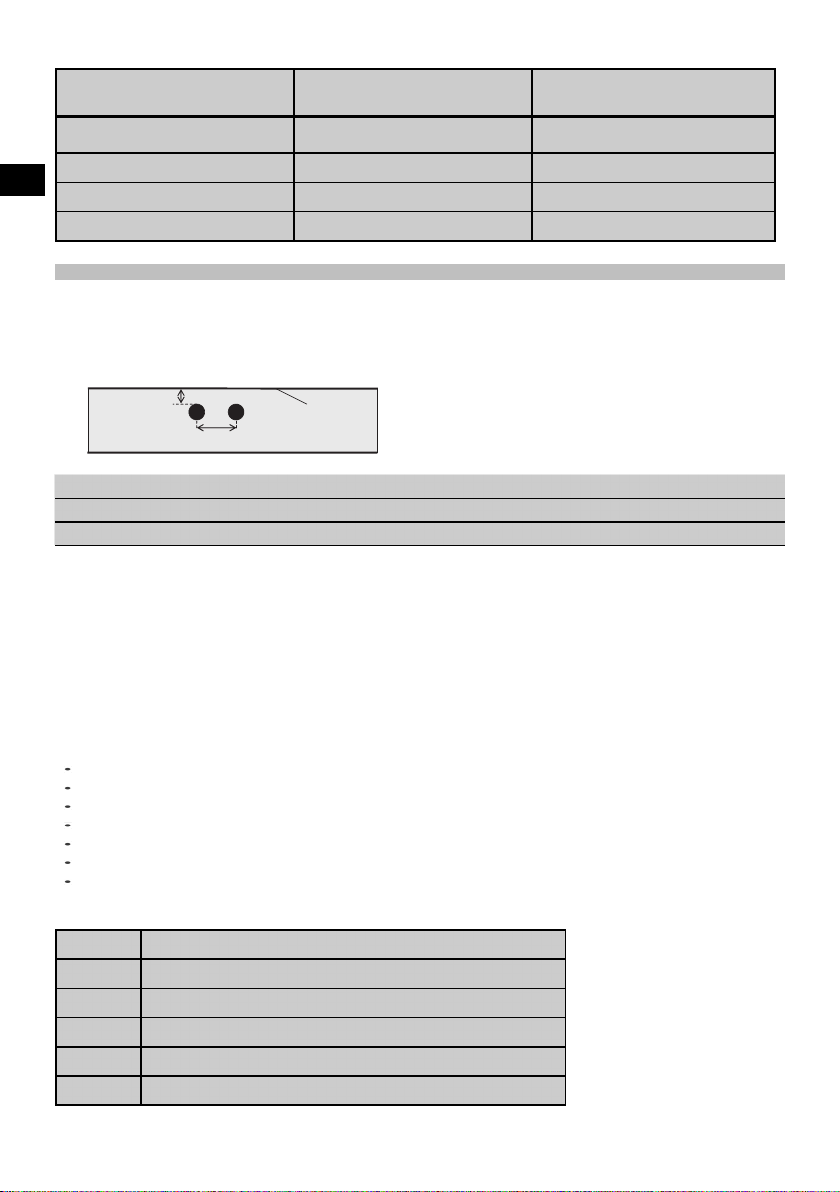
This is defined as:
c
Depth of cover
s
Spacing
F
V
;
XSurface
In order to be able to resolve and locate individual bars, the ratio of bar spacing (s) to depth of cover (c) must be at
least 2:1. Minimum bar spacing is 36 mm (1.4"). The higher of the two values applies when resolving individual bars. A
depth of at least c≧10 mm (0.4") is required in order to carry out a depth measurement.
NOTE
Place a sheet of non-metallic material (e.g cardboard, wood, polystyrene foam,...) between the scanner and the surface
to be scanned if the minimum depth cannot be adhered to.
The starting point and finishing point of the scan (e.g. from the edge of the reference grid) must be at least 30 mm
(1.2") away from the nearest reinforcing bar.
In the annex of these operating instructions you will find bar diameter tables in accordance with:
DIN 488
ASTM
CAN
JIS
GB 500110-2002
GOST 5781-82
BIS 1786:1985
Explanation of the bar diameter tables in the annex
∅ [mm] Bar diameter in mm
∅
↧[in]
↧ [mm]
Bar diameter
Depthininches
Depthinmm
0 Bar is visible at this depth but no depth is calculated.
X Bar cannot be detected at this depth.
8
Page 12

The value indicates the typical accuracy of the depth measurement (deviation
from actual) in mm or, respectively, in inches.
4.3.1 Imagescan and Blockscan: Rebar diameter is known
Pleaserefertothebardiametertablesintheannex(1.).
4.3.2 Imagescan and Blockscan: Rebar diameter is not known
Pleaserefertothebardiametertablesintheannex(2.).
4.3.3 Quickscan recording: Rebar diameter is known
Pleaserefertothebardiametertablesintheannex(3.).
4.3.4 Quickscan detection with depth measurement: Rebar diameter is known
Pleaserefertothebardiametertablesintheannex(4.).
4.3.5 Quickscan detection
Depth measurement is accurate to within ±10% of the effective depth.
4.3.6 Accuracy of bar diameter measurement
± 1 standard diameter when rebar spacing : depth of cover ≥ 2 : 1. Bar diameter measurement is possible only at
depths of up to 60 mm (2.4").
4.3.7 Reinforcing bar location accuracy
Bar center locating accuracy (all modes): Typically ± 3 mm (0.12") relative to the measured position, when the ratio of
bar spacing : depth of cover is ≥ 1.5:1.
4.4 Technical data for PS 200 S scanner
Maximum scanning speed 0.5 m/sec (1.64 ft/s)
Memory type Built-in flash memory for data
Memorycapacity 9Imagescansplusupto30m(98ft)ofrecorded
Quickscan (max. 10 scans)
Screentype/size LCD/50×37mm(2"x1.5")
Screen resolution 128 × 64 pixels
Dimensions 260×132×132mm(10.2x5.2x5.2")
Weight (with PSA 80 battery pack) 1.4 kg (3.09 lb)
Minimum battery life (with PSA 80 battery pack) 8 hours under typical conditions
Automatic power-off 5 min. after last press of a button
Backup battery type / life Lithium / 10 years (typically)
Scanner-monitor data interface Infrared
Scanner-monitor data transfer time ≦16 s for 9 images, ≦2 s for 1 image
Infrared range Typically 0.3 m (1 ft)
Infrared output power Max. 500 mW
en
4.5 Technical data for PSA 55 infrared adapter
Battery 1 x 1.5 V AAA
Dimensions 90 x 50 x 28 mm (3.5 x 2 x 1.1")
Weight 65 g (0.14 lb)
9
Page 13
Scanner - adapter data interface IrDa
Adapter - computer data interface USB
en
5 Safety instructions
In addition to the information relevant to safety given
in each of thesections ofthese operatinginstructions,
the following points must be strictly observed at all
times.
5.1 Intended use
a) The tool and its ancillary equipment may present
hazards when used incorrectly by untrained personnel or when used not as directed.
b) To avoid the risk of injury, use only genuine Hilti
accessories and additional equipment.
c) Modification of the tool or tampering with its parts
is not permissible.
d) Observe the information printed in the operat-
ing instructions concerning operation, care and
maintenance.
e) Do not render safety devices ineffective and do
not remove information and warning notices.
f) Check the condition of the tool before use. If the
tool is found to be damaged, have it repaired at a
Hilti Service Center.
g) In particularly critical situations where measurements
have safety and structural stability implications, always check results by removing material from the
surface of the structure and physically checking the
position, depth and diameter of reinforcement at key
positions.
h) When drilling at or near to a bar indicated by the sys-
tem, never drill deeper than the bar depth indicated.
5.2 Proper organization of the workplace
a) Keep the workplace tidy. Objects which could
cause injury should be removed from the working area. Untidiness at the workplace can lead to
accidents.
b) Keep other persons, especially children, away
from the area in which the work is being carried
out.
c) Wear non-skid shoes.
d) Avoid unfavorable body positions when working
from ladders. Make sure you work from a safe
stance and stay in balance at all times.
e) Only use the tool within the defined limits.
f) Check with a qualified person that it is safe to drill at
a specified point before beginning drilling.
g) Donotusethetoolwherethereisariskoffireor
explosion.
h) Make sure that the toolbox is properlysecured during
transport and does not present a risk of injury.
5.3 Electromagnetic compatibility
Although the tool complies with the strict requirements of
the applicable directives, Hilti cannot entirely rule out the
possibility of interference to the tool caused by powerful
electromagnetic radiation, leading to incorrect operation.
Accuracy must be checked by taking measurements by
other means when working under such conditions or
if you are unsure. Likewise, Hilti cannot rule out the
possibility of interference with other devices (e.g. aircraft
navigation equipment).
5.4 General safety precautions
5.4.1 Mechanical safety precautions
a) Check the tool for damage before use. If the tool
is found to be damaged, have it repaired at a Hilti
Service Center.
b) You must check the accuracy of the tool after it
has been dropped or subjected to other mechanical stresses.
c) When the tool is brought into a warm environment
from very cold conditions, or vice-versa, allow it
to become acclimatized before use.
d) Although the tool is protected against the entry of
moisture,itshouldbewipeddrybeforebeingput
away in its transport container.
5.4.2 Electrical safety precautions
a) Avoid short circuiting the battery terminals. Check
that the terminals on the battery pack and in the tool
are free from foreign objects before inserting the
battery pack. Short circuiting the battery terminals
presents a risk of fire, explosion and chemical burns.
b) Make sure that the outer surfaces of the battery
pack are clean and dry before inserting it in the
charger. Observe the operating instructions for
the charger.
c) Use only the battery pack specified in these operating
instructions.
d) Batteries that have reached the end of their life must
be disposed of safely and correctly to avoid environmental pollution.
e) Remove the battery pack before transporting the tool
or storing it for a long period of time. Inspect the
battery pack for any signs of leakage or damage
before reusing it.
f) To avoid pollution of the environment, the tool
must be disposed of in accordance with the cur-
10
Page 14
rently applicable national regulations. Consult the
manufacturer if you are unsure of how to proceed.
5.4.3 Liquids
c) Do not use the tool if it is defective.
d) If you are unsure of the scan results, consult a Hilti
specialist before proceeding.
e) Observe all warning and information messages dis-
played by the scanner and monitor.
Caustic liquids may leak from defective batteries. Avoid
contact with these liquids. In case of skin contact, wash
the area affected with soap and plenty of water. In case
of eye contact, rinse the eyes immediately with water and
subsequently consult a doctor.
5.5 Requirements to be met by users
a) The tool may be operated, serviced and repaired
only by authorized, trained personnel. This personnel
must be informed of any special hazards that may be
encountered.
b) Concentrate on your work. Stay alert. Pay atten-
tion to what you are doing. Approach the work
with common sense. Do not use the tool if you
are not concentrating.
6Beforeuse
6.1 Charging the battery pack
Use the PUA 80 charger to charge the PSA 80 battery
pack. Full instructions are contained in the charger operating instructions. The battery pack must be charged for
14 hours before first use.
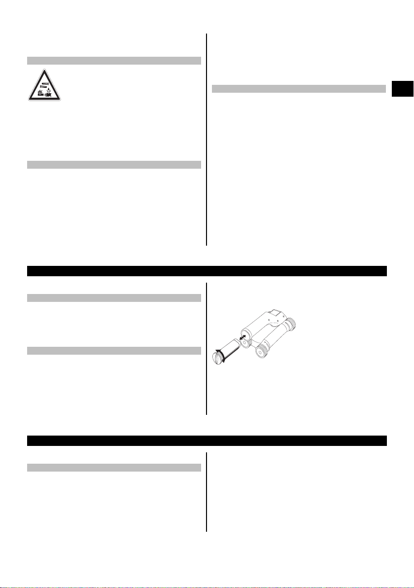
6.1.1 Inserting and removing the battery pack
CAUTION
The battery pack must slide easily into the scanner. Do
not use force when inserting the battery pack into the
scanner as this may damage the battery pack and/or the
scanner.
5.6 Scanning requirements and limitations
a) Always check the accuracy of the tool before com-
mencing work on structures where measurements
have safety and structural stability implications. Scan
a reinforcing bar of known location, depth and diameter and check the results against the accuracy
specifications.
b) Do not use the PS 200 S scanner if the wheels do
not turn freely or appear to be worn. Contact Hilti for
repair information. The wheels may also be cleaned
or replaced by the user.
c) Always check how the tool is configured before
using it.
d) Applyonly light pressure to the scanner when moving
it across the surface.
e) Reinforcement that lies beneath the uppermost layer
of reinforcement may not be detected.
f) Remove all metal items of jewelry such as rings, pen-
dants, bracelets, etc. before commencing scanning.
Check that the battery pack is correctly aligned with the
scanner. When the battery pack end cap is facing you,
the large groove in the battery pack must be on the left.
n
a
c
s
o
rr
e
F
0
0
2
S
P
Push the battery pack into the opening as far as it will go.
Turn the end cap clockwise until it clicks into place.
To remove the battery pack, turn the end cap anticlockwise as far as it will go. Pull the battery pack out of
the scanner.
en
7Operation
7.1 Carrying and using the system
CAUTION
The temperature inside a motor vehicle exposed to the
heat of the sun can easily exceed the maximum permissiblestoragetemperatureforthePS250Ferroscansystem. Some of the components of the PS 250 Ferroscan
system may suffer damage if exposed to temperatures
exceeding 60°C (140°F).
The scanner can be used without the monitor for scanning, or the monitor can be carried in the PSA 64 soft
pouch. The first option is advantageous when working
in areas that are difficult to access and maximum mobility is required, such as on a scaffold or ladder. When
scanner memory is full (9 Imagescans made, 1 complete
Blockscan or 30 mm (98 ft) of Quickscan have been
recorded) the data can be transferred to the PSA 55
infrared adapter or the PSA 100 monitor. The monitor
11
Page 15
can be kept nearby (e.g. at the foot of the scaffold, in a
vehicle, in the site office etc.). When the user intends to
make more scans than the scanner is capable of storing
7.2 Operating the scanner
en
7.2.1 Control panel and display
Control panel
1
2
3
4
5
Display
2
13
in its memory and wishes to avoid repeated journeys to
the monitor, the PSA 55 infrared adapter can be used
or the monitor attached to a belt or carried using the
shoulder strap supplied.
Arrow but-
@
tons
Confirm
;
button
On/off but-
=
ton
Cancel but-
%
ton
Record
&
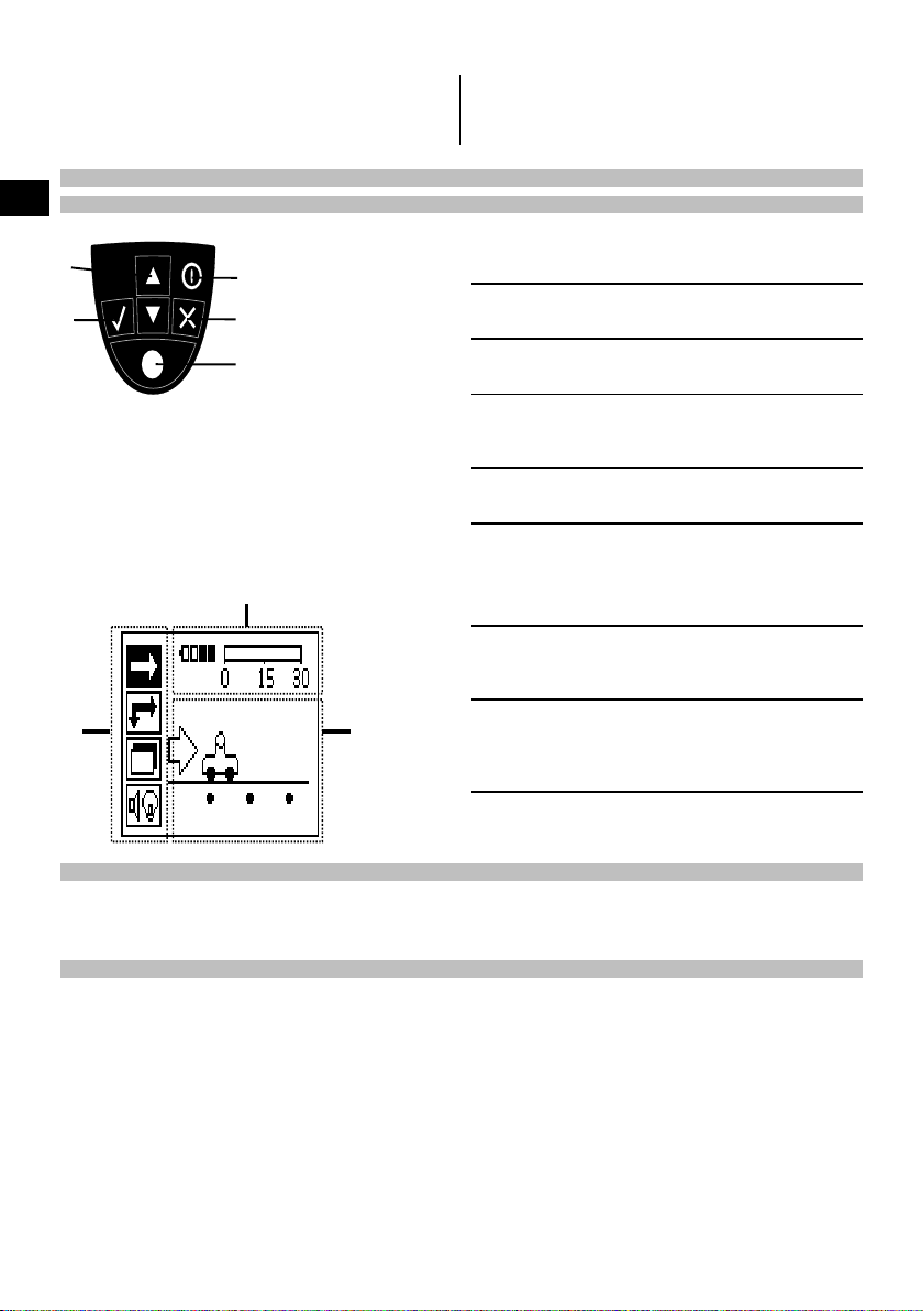
button
Menu area. Functions that can be selected
@
Status in-
;
formation
Variable
=
area.
Toggle up or down in options or
values.
Confirms a value or a selection.
Switches the tool on or off.
Cancelsaninput,cancelsthe
path being scanned or goes
back one step within a menu.
Starts or stops a recording.
using the Arrow and Confirm
buttons
Informationsuchasbattery
charge status and memory
status.
This is where feedback / information for the user is displayed,
e.g. scanning mode, bar depth,
scanning progress, etc.
7.2.2 Switching on and off
Press the on / off button to switch the scanner on or off.
The scanner can be switched off only when the main menu is displayed. To reach this screen, press the Cancel button
repeatedly until the main menu is displayed.
7.2.3 Main menu
The system always starts in the main menu. All scanning functions and set-up options are selected here. The battery
charge status is displayed at the top of the screen together with the memory status. The various scan modes and
settings menus are displayed as symbols on the left side of the screen. Use the Arrow buttons to toggle between
these options. Press the Confirm button to confirm the selected option.
12
Page 16
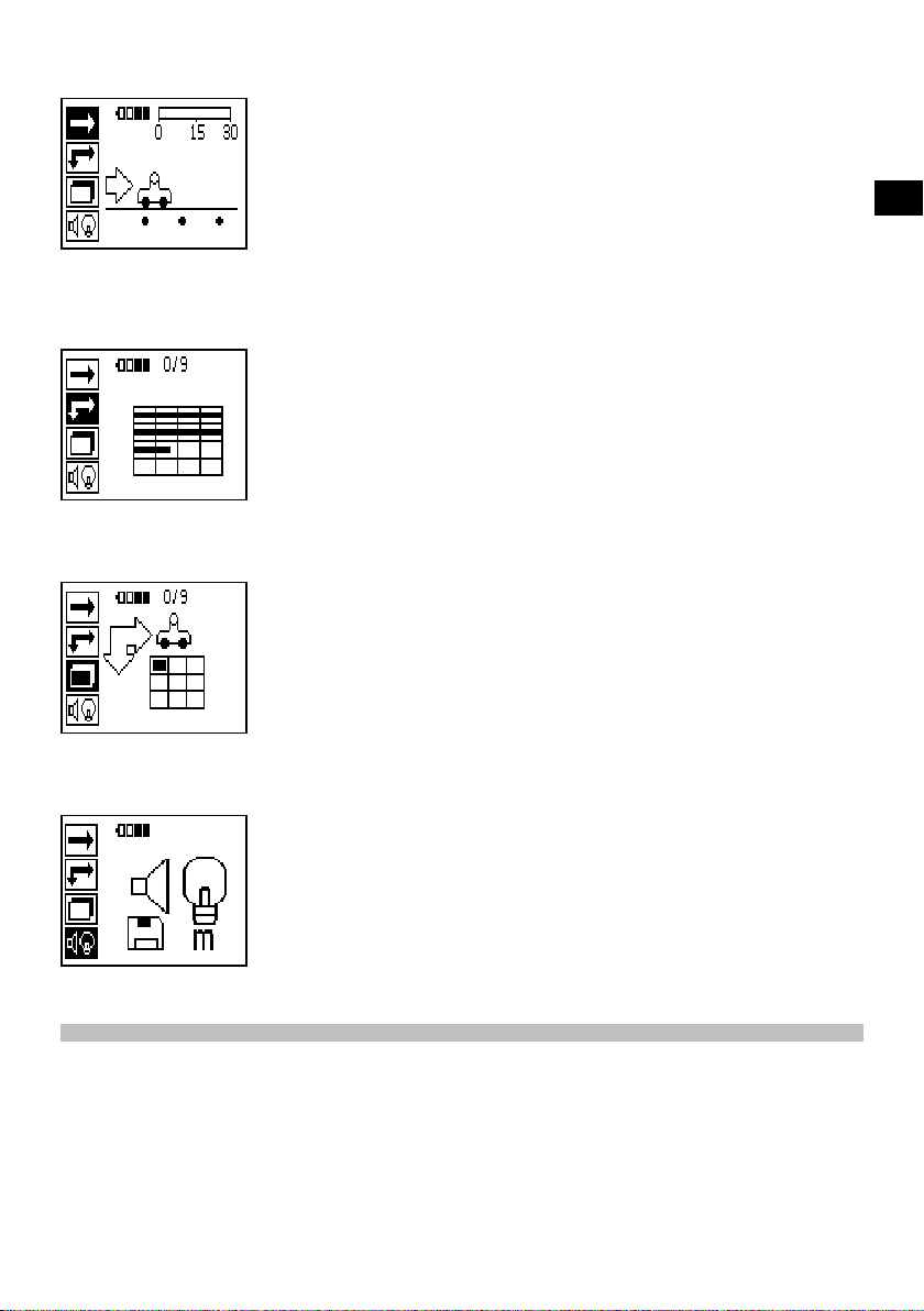
Quickscan
The remaining memory for Quickscan recording is shown at the top of the screen in meters or feet (depending on the
scanner type and units set).
Imagescan
The number of Imagescans in the scanner, up to a maximum of 9, is shown at the top of the screen.
Blockscan
en
The number of Imagescans in the scanner, up to a maximum of 9, is shown at the top of the screen.
Settings
Sets various parameters and deletes all scans held in memory.
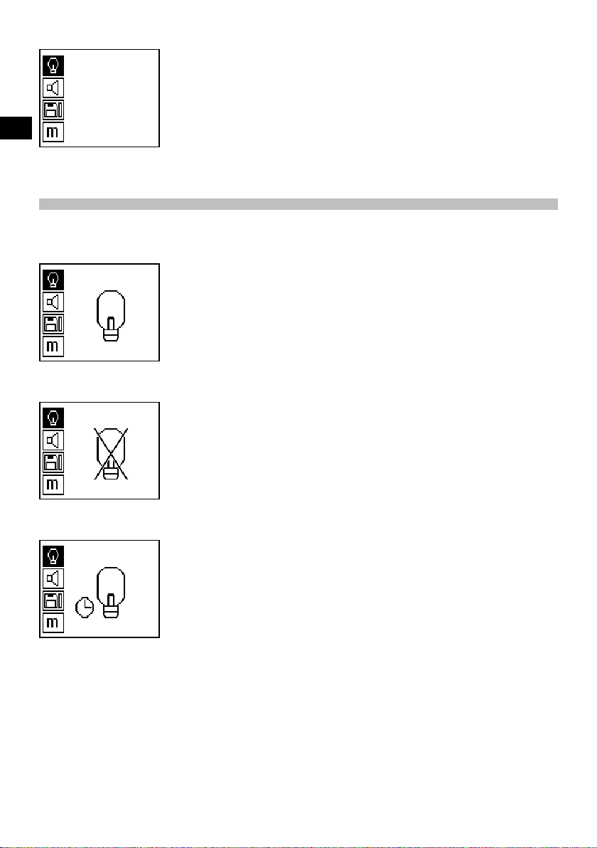
7.2.4 Settings
This menu is used to set general parameters and to delete data from scanner memory.
After opening the settings menu, this screen appears.
13
Page 17
en
The Arrow buttons are used to select the options. The selected option can be confirmed / activated by pressing the
Confirm button and the Cancel button then pressed to return to the main menu.
7.2.4.1 Set display backlight
Select the backlight adjustment function by pressing the Confirm button. Use the Arrow buttons to toggle between
the individual options. Press the Confirm button to select the desired option and press the Cancel button to return to
the settings menu.
Switch backlight on
Switch backlight off
Backlight is controlled automatically. With this option, the backlight is switched off automatically after 5 minutes if no
button is pressed during this time and is switched back on again the next time a button is pressed.
14
Page 18
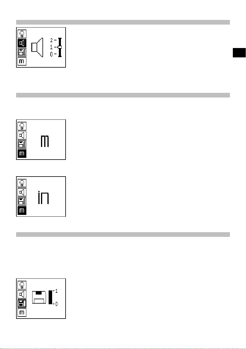
7.2.4.2 Adjusting the volume
Sets the volume level of the audible signal during scanning. Use the Arrow buttons to toggle between the various
options. Press the Confirm button to select the desired option and press the Cancel button to return to the settings
menu.
7.2.4.3 Setting the units
On systems with the item nos. 2044436, 2044474 and 377649 can the unit of measure used for scanning can be
configured by the user. Use the Arrow buttons to toggle between the various options. Press the Confirm button to
select the desired option and press the Cancel button to return to the settings menu.
Metric (mm or m, as appropriate)
en
Imperial (feet, as appropriate)
7.2.4.4 Deleting data
Deletes all scan data stored in the scanner. This function is available only if data is contained in memory. If data is
contained in memory, the bar shown next to the diskette symbol is filled. The bar is shown empty when no data is
contained in memory.
NOTE
Deleting memory contents presents a risk of losing data. Data that has not been transferred to the monitor before
deletion will be permanently lost.
15
Page 19

Press the Down arrow button followed by the Confirm button to delete data. Alternatively, press the Cancel button to
return to the settings menu.
7.2.5 Quickscan
CAUTION
The scanner detects only reinforcing bars that lie at right angles to the direction of travel. Bars that lie parallel to the
direction of travel will not be detected.
en
Make sure that the object is scanned in both the horizontal and vertical directions.
An incorrect depth may be calculated for bars that lie diagonal to the direction of travel.
Quickscan can be used to quickly detect the positions and approximate depths of reinforcing bars, which can then be
marked on the surface. This is procedure is named Quickscan detection.
Another function in Quickscan mode is accurate depth measurement, which requires that values for bar diameter and
bar spacing are previously entered.
Alternatively, the data can be recorded and evaluated on the monitor or using the PC application. The average depth
of cover over the reinforcement over large stretches of the surface can thus be easily determined. This procedure is
known as Quickscan recording.
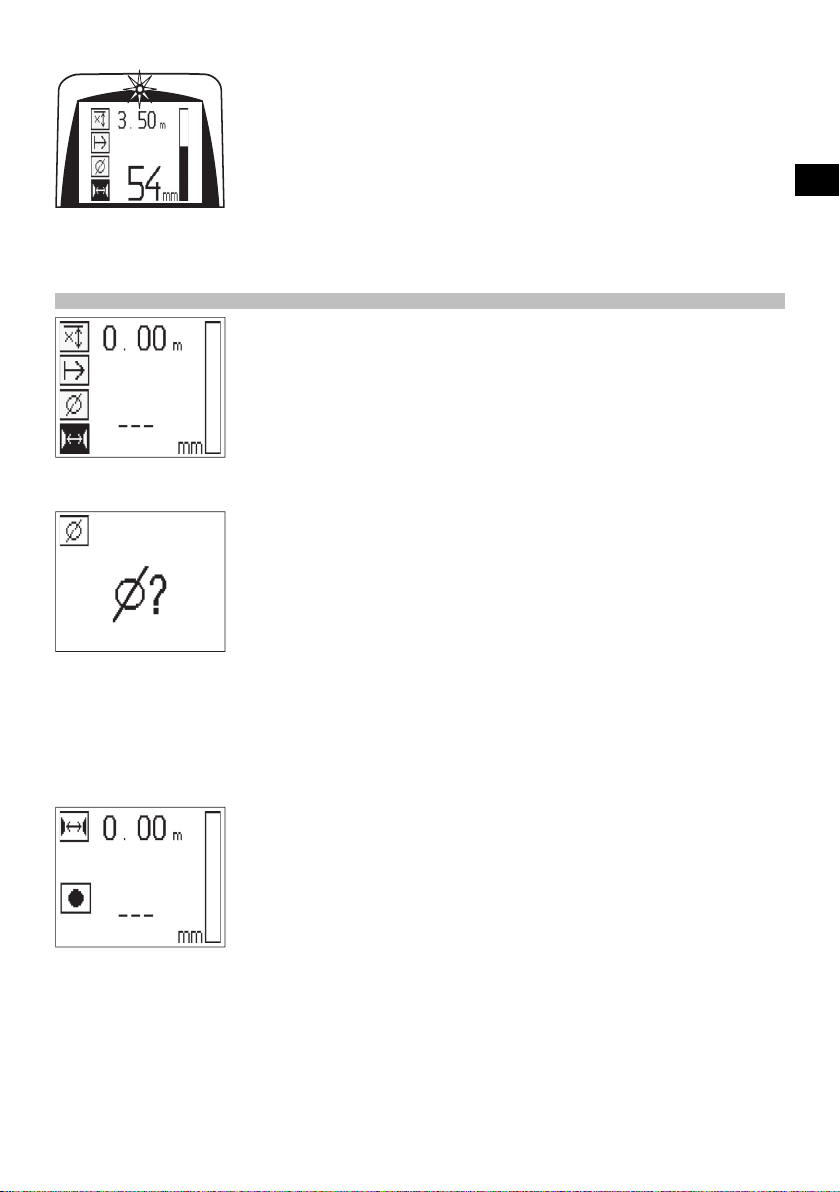
Switch on the scanner. The Quickscan symbol is selected first automatically.
Use the Confirm button to select the Quickscan function from the main menu.
Bar depth
@
Distance traveled
;
Signal strength
=
Settings: Minimum depth, scanning direction,
%
bar diameter, bar spacing
7.2.5.1 Quickscan detection
Move the scanner over the surface. Reinforcing bars that lie at right angles to the direction of travel will be detected.
The distance covered by the scanner is recorded.
Signal strength indicated by the column in the display increases as the scanner approaches a bar and the depth value
is also shown. When the scanner is positioned over the center of a reinforcing bar:
The red LED lights.
A signal tone is emitted.
Maximum signal strength is indicated.
The approximate depth of the bar is indicated (lowest depth value indicated = center of the bar).
16
Page 20
The bar is positioned along the center line of the scanner and may be marked on the surface using a PUA 70 marking
pen. Depth measurement accuracy can be increased by entering the correct rebar diameter or by switching to accurate
depth measurement measuring mode (see 7.2.5.2).
7.2.5.2 Quickscan with accurate depth measurement
The measuring mode “Quickscan with accurate depth measurement” is selected by pressing the Confirm button.
The correct diameter must be known and previously entered.
The bar spacing distance must also be entered if within the 36 mm≦s≦120 mm (1.4"≦s≦4.7") range (see 4.3). This
value can be taken from building plans, confirmed by chipping away a channel in the concrete to view the bars, or
measured using Quickscan detection.
NOTE
A rebar spacing distance s≦36 mm (1.4") (see 4.3) cannot be measured.
en
The bar spacing distance can be calculated automatically using the Quickscan detection function by searching for
the center of the bar and pressing the red Record button when the scanner is over the mid point of the bar. Find the
mid point of the next bar and then press the Record button again. Bar spacing is then calculated automatically and
recorded.
17
Page 21

en
If the spacing distance is known, the value can also be entered manually using the Arrow buttons.
After setting the bar diameter and the spacing distance, the procedure is exactly the same as for Quickscan detection
( see 7.2.5.1).
7.2.5.3 Quickscan recording
WARNING
Always make an Imagescan or use Quickscan detection in both directions prior to making a Quickscan recording in
order to:
– establish the direction of the uppermost layer of reinforcement,
– minimize the risk of scanning a spliced bar,
– and immediately see if there are any ferrous materials in the concrete that may affect the accuracy of the scan.
CAUTION
Do not press the Record button before placing the scanner at the point where the scan should begin.
The scan should not, under any circumstances, be started or stopped while the scanner is directly over a bar. Keep
an eye on the display (observe a distance of at least 30 mm (1.2") to the nearest reinforcing bar).
Incorrect or misleading measurements may otherwise result.
WARNING
Do not lift the scanner from the surface before stopping the recording or setting a marker.
To record the position and depth of all reinforcing bars detected, place the scanner on the surface and use Quickscan
detection to find a position where there are no bars present. Mark the startingpointwithaPUA70markingpenand
press the Record button. The diskette symbol appears on the screen, indicating that the scanner is recording data.
Move the scanner over the surface.
Attheendofthescan,takecaretoensurethattheendpointisnotdirectlyover a rebar. To stop recording, press
Record again. Use a PUA 70 marking pen to mark the end of the stretch that has been scanned.
NOTE
Reinforcing bars that lie at right angles to the direction of travel will be detected and automatically recorded. Check to
ensure that the settings are correct before beginning recording.
18
Page 22

A stretch of up to 30 m (98 ft) in length can be recorded before it is necessary to transfer the data to the PSA 100
monitor or the PSA 55 infrared adapter. It is also possible to record several separate stretches (max. 10) that add up
to a maximum of 30 m (98 ft).
The data recorded can be transferred to the monitor for analysis ( see section 7.4.1).
7.2.5.4 Quickscan settings
The Quickscan settings are shown on the left hand side of the display. The settingscanbemadebeforemakinga
QuickscanoraQuickscanwithaccuratedepthmeasurement.UsetheArrowbuttons and Confirm button to access
the settings.
Limited depth scan
NOTE
This measurement mode allows rebars to be located within a specified depth range.
NOTE
When using the tool in this mode, the preset depth must take a clearance distance from the rebar into account.
Minimum depth
Use this setting when scanning a surface and looking specifically for bars that are located within a certain depth. For
example, if checking for 40 mm (1.6") minimum depth of cover, set the value to 40 mm (1.6"). (For quality assurance
measurements add an extra 2 mm (0.08") to account for any accuracy limitations). A signal tone is emitted and the
LED lights only if a reinforcing bar located within 40 mm (1.6") of the surface is detected.
CAUTION
Before making a scan, check to ensure that the depth range restriction is set correctly or deactivated if this feature is
not required.
en
Use the Arrow buttons to select the minimum depth function and then press Confirm.
Minimum depth function disabled.
When the value is set to "0", the function is deactivated and appears as above. Use the Arrow buttons to enter the
desired depth value and then confirm the setting by pressing the Confirm button. The system returns to the main
menu.
NOTE
If reinforcing bars are located at depths greater than the minimum depth set, no signal tone is emitted and no LED
lights.
Scanning direction
This setting is used to set the direction in which Quickscan recording is performed. Although they have no direct
effect on any measurement values later obtained from the monitor or PC application, the settings help to ensure that
19
Page 23

individual Quickscan recordings are subsequently correctly displayed in Hilti PROFIS Ferroscan MAP (data evaluation
and presentation application) and that the depth values correspond with the actual surface of the structure. This
makes it easier to subsequently locate the positions of areas with inadequate cover. The scanning direction is saved
together with each scan.
en
Select the desired scanning direction and press the Confirm button.
Bar diameter
This setting must be made in order to obtain an accurate depth of cover measurement (= rebar depth). Depth can be
measured accurately only when correct rebar diameter has been entered.
Use the Arrow buttons to select the bar diameter function and then press the Confirm button.
If no bar diameter is selected, the scanner will take the average diameter value for the relevant standard setting range
and calculate the depth accordingly.
CAUTION
Use the “Unknown diameter” function only under exceptional circumstancesastheresultsofthescanmaybe
distorted considerably if rebars of a different diameter have, in fact, been incorporated in the structure.
Average bar diameter according to standards
Standard
DIN 488 16 mm (0.63")
ASTM A 615 / A 615M‑01b
CAN / CSA-G30, 18-M92 C 20
JIS G 3112 D 22
GB 50012-2002 18 mm (0.71")
GOST 5781-82 18 mm (0.71")
BIS 1786:1985 16 mm (0.63")
∅
#7
NOTE
The bar diameter previously set will be saved in the scanner when switching it off. Check each time before using the
scanner that the rebar diameter has been preset correctly.
20
Page 24

7.2.5.5 Setting a marker
The surfaces of many structures contain obstacles that make it impossible to record the scan without lifting the
scanner from the surface. Examples of such obstacles are piers or columns on a wall, door openings, expansion joints,
pipes, scaffold bars, corners etc.
If an obstacle is encountered, a marker can be set. This interrupts the scan and allows the user to lift the scanner away
from the surface, place it beyond the obstruction and then continue scanning. It also indicates where certain objects
are located within a scan, providing additional information that creates a reference between the scan data and the
actual surface.
To set a marker, press and hold the Confirm button while in recording mode. The diskette symbol will be crossed out,
indicating that recording has been suspended and a marker has been set.
CAUTION
Due to interruption of the recorded signal, scanning results are less accurate immediately before and after the point
where a marker is set.
Do not interrupt the scan at the position of a reinforcing bar.
Then lift the scanner from the surface while keeping the Confirm button pressed. If necessary, mark the position on
the surface using a PUA 70 marking pen. Place the scanner back on the surface beyond the obstacle, release the
Confirm button and continue scanning. The marker will be shown as a vertical line in the scan data when viewed on
the monitor or in the PC application.
7.2.6 Imagescan
Imagescan is used to create an image of the reinforcement layout. The depth and diameter of the bars can be
determined or, respectively, estimated.
A reference grid must first be fixed to the wall. Use the adhesive tape supplied for this purpose. This tape adheres well
to concrete and can be torn off the roll by hand in the lengths required. For most surfaces, a 10 cm (4") length of tape
at each corner is adequate to secure the grid. If the concrete surface is very damp or dusty, use the brush supplied to
clean off any dirt and dust. The reference grid may then have to be attached by applying a strip of tape along the full
length of each edge.
Alternatively, a grid can be marked directly on the surface. Using a straight edge (such as a piece of wood) as a
guide, mark out a 4 x 4 grid with the parallel lines spaced at intervals of 150 mm (6"). The holes punched in the paper
reference grid can also be used to mark the positions of the grid lines on the concrete surface.
Switch the scanner on and select the Imagescan symbol. The battery level is displayed together with the number of
Imagescans currently held in memory (a maximum of 9).
en
Select Imagescan from the main menu.
The Imagescan screen is displayed.
21
Page 25

en
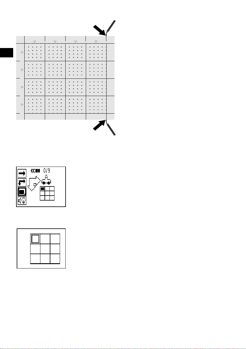
A representation of the grid appears on the screen with a suggested starting point (triangle). This is always at upper
left and will be suitable for most scans. Image data will be generated only for areas of the grid that have been scanned
both vertically and horizontally. In some cases, obstacles in the scan area may prevent this (e.g. a pipe penetrating a
beam). The starting point may be changed in such cases in order to allow the areatobescannedoptimally.Usethe
Arrow buttons to change the starting point if necessary.
5
150
PS 200 S Ferroscan
Æ
1
Æ
150
PS 200 S Ferroscan
2
Place the scanner on the grid at the starting point shown by the blinking arrow. Ensure the alignment marks on the
scanner are aligned correctly with the reference grid as shown above.
NOTE
Incorrect alignment of the scanner on the reference grid may lead to the bar positions being incorrect in the image
generated.
Press Record and move the scanner along the first row. Scanning progress is indicated by a thick black line that
advances across the display as the scanner is moved over the surface.
22
Page 26

PS 200 S Ferroscan
Æ
Æ
PS 200 S Ferroscan
The scanner emits a double beep at the end of the row and automatically stops recording. This procedure should be
repeated for each row and column while observing the instructions shown in the display.
When all rows have been completed, the columns should also be scanned in the same way.
The scanning operation for any row or column may be interrupted before reaching the end by pressing Record again.
This may be necessary if an obstacle prevents the full path being scanned. Similarly, an entire row or column may be
skipped by starting and stopping the recording without running the scanneroverthegrid.
Please note that no image will be created for areas of the reference grid that are not scanned in both directions.
It is possible to repeat the previous row or column by pressing Cancel. This may be necessary if the user is not
sure whether the path to be scanned has been followed accurately or if the scanner slipped out of position. Pressing
Cancel a second time aborts the scan and the system then returns to the main menu. Press Confirm to save the scan.
Pressing Cancel after scanning the last column or row will cause the scan to be deleted.
When the scan is complete, press the Confirm button to return to the main menu. The data can be transferred to the
monitor for viewing and evaluation ( see 7.4.1).
7.2.7 Blockscan
Blockscan automatically stitches Imagescans together to provide an impression of the reinforcement layout over a
large area. The exact bar position, depth and diameter can also be determined on the monitor by selecting each
Imagescan individually.
en
23
Page 27
5 6 7 8
en
150
1
150
300 450 600
2
300
3
450
4
600
Attach the reference grid in the same way as for an Imagescan. Use a PUA 70 marking pen to mark the edges or the
punched holes at the end of each reference grid for the transition to the next grid, as shown below. Any additional
reference grids required should be attached to the wall so that their edges correspond and are in alignment with each
other.
Switch the scanner on and use the Arrow buttons to select the Blockscan symbol from the main menu. The battery
level is displayed together with the number of Imagescans currently held in memory (a maximum of 9).
A representation of a Blockscan is shown on the screen. Each square represents an Imagescan. Up to 3 x 3 Imagescans
can be made. Use the Arrow buttons to select the position of the first Imagescan to be made. Press Confirm to begin
the first Imagescan. Note that the coordinates of any points on the Blockscan will be referenced from the upper left
corner.
For details of how to carry out the Imagescan, see 7.2.6. When the Imagescan is complete, the system returns to the
Blockscan screen.
24
Page 28

The completed Imagescan is shown shaded.
en
5 6 7 8
150
1
150
2
300
3
450
4
600
300 450 600
5 6 7 8
150
1
150
2
300
3
450
4
600
300 450 600
Select the next Imagescan position and repeat the scanning procedure. Imagescans already made may be repeated
simply by reselecting the area to scan and carrying out the Imagescan again. The data will be overwritten. Once all the
Imagescans have been recorded, or the maximum number of scans that can be held in memory is reached (9), press
the Cancel button to return to the main menu. Transfer the data to the monitor for viewing and analysis ( see 7.4.1).
NOTE
Pressing the Cancel button twice causes the recorded Imagescan to be deleted. The screen then returns to the main
menu.
7.3 PSA 55 infrared adapter
7.3.1 Before first use
NOTE
Install the Hilti PROFIS Ferroscan 5.7 software (or a higher
version) on your PC/laptop. The date and time must be
set before using the PSA 55 IR adapter for the first time
in order to ensure that the scan data subsequently shows
the correct date and time.
To do this, use the PUA 95 Micro USB cable to
connect the PSA 55 IR adapter to the computer.
Start the Hilti PROFIS Ferroscan application.
Go to “Tools”, “Workflow” and then select “Set PSA
55 date and time”.
The date and time are then set in the PSA 55 IR
adapter.
NOTE
The device driver is installed together with the Hilti
PROFIS Ferroscan (V 5.7) software. If this is not the
case, the device driver must be installed manually by
running the “setup.exe” file located in the “Drivers” folder
on the PSA 55 IR adapter.
7.3.2 Operating the PSA 55 infrared adapter
The scans can be transferred to the adapter via the
infrared interface and from there to the PC/laptop.
Switch the adapter on or off by pressing the on / off
button for about 3 seconds.
The LED display on the adapter can indicate the following
statuses:
25
Page 29

The green LED lights constantly: The adapter is
switched on and is ready for operation.
The red LED blinks rapidly: Battery charge state is
low.
The green LED blinks: The adapter has just been
switched on.
en
ThegreenLEDblinks:Datatransferinprogress.
The red LED blinks and the adapter switches itself
off: Memory is 95% full.
7.4 Data transfer
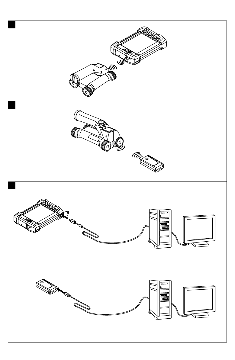
7.4.1 Transferring data from the scanner to the
monitor 2
NOTE
Ensure that the correct project is selected on the monitor
before transferring data.
NOTE
Check that the windows over the infrared ports are
free from dirt, dust and grease and are not excessively
scratched before commencing data transfer. Failure to
do so may result in reduced data transfer range or may
prevent data transfer.
Data is transferred from the scanner to the monitor using the infrared connection. The infrared windows are
situated at the ends of scanner and the monitor.
Data can be transferred at any time when the scanner
and monitor are switched on, the PS 200 S scanner is
displaying the main menu and data transfer by infrared is
activated on the monitor.
The project into which the data is to be copied is selected
on the monitor under Projects.
Then select Import and confirm “From PS 200 S” by
pressing the OK button. The infrared symbol then appears
in the status area of the PSA 100 monitor.
Bring the scanner and monitor close together so that
the infrared windows are facing each other. The two
devices recognize each other automatically and establish
communication.
This screen appears on the scanner and a beep sounds:
Press the Confirm button on the scanner to begin importing all scan data into the selected project.
This screen appears on the scanner while data transfer
is in progress and the red LED on the scanner blinks
continuously.
Data transfer takes between 1 and 15 seconds, depending on the number and length of scans contained in the
scanner.
This screen is displayed by the scanner when data transfer is complete:
Press the Confirm button on the scanner again to end the
data transfer procedure.
The scan data in the scanner is then deleted automatically.
7.4.2 Transferring data from the scanner to the
adapter 3
DANGER
Use the adapter only indoors. Avoid moisture ingress.
CAUTION
Check that the windows over the infrared ports are
free from dirt, dust and grease and are not excessively
scratched before commencing data transfer.
Failure to do so may result in reduced data transfer range
or may prevent data transfer.
Data is transferred from the scanner to the adapter using the infrared connection. The infrared windows are
situated at the ends of scanner and the adapter.
NOTE
The maximum range of the infrared connection is approximately 30 cm (11.8"). The maximum permissible angle
between the scanner and monitor for successful data
transmission at close ranges (up to 10 cm (4")) is ± 50°
relative to the axis of the infrared port on the adapter.
At a distance of 15 cm (6") this angle is reduced to ±
30°. At a distance of 30 cm (11.8") the scanner must be
accurately aligned with the monitor to ensure successful
data transmission.
Bring the scanner and adapter close together so that
the infrared windows are facing each other. The two
devices recognize each other automatically and establish
communication. The following screen appears on the
scanner and a beep sounds:
26
Page 30
Press the Confirm button on the scanner to begin data
transfer. The following may be observed while data transfer is in progress:
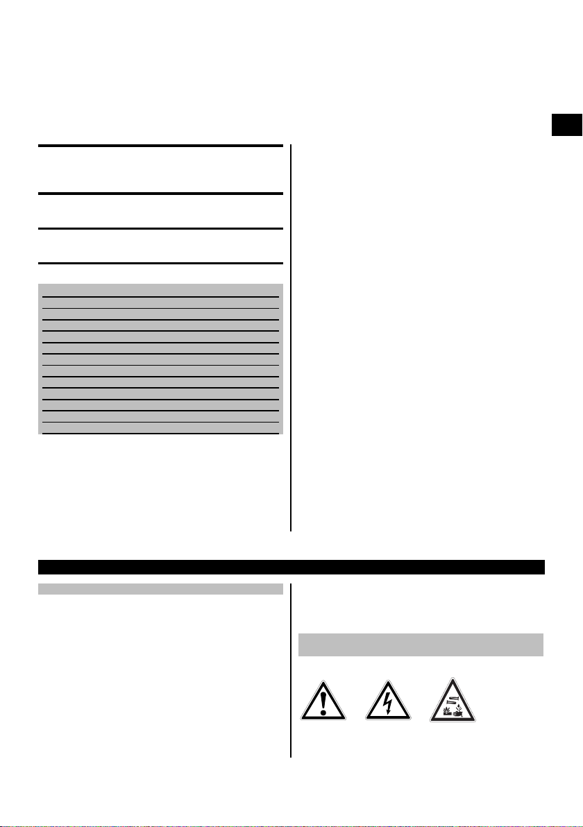
The PSA 92 USB data cable is used to transfer data from
the monitor to the computer.
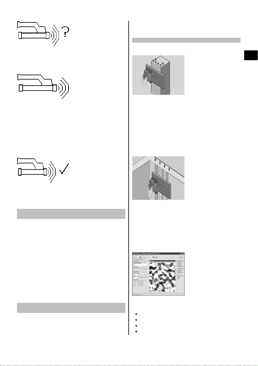
7.5 Tips for scanning and evaluation
The object is too narrow to scan or reinforcement is
too close to an outside edge to be scanned properly.
en
The green LED on the adapter blinks rapidly to indicate
that data transfer is in progress. The red LED on the
scanner blinks continuously.
Data transfer takes between 1 and 15 seconds, depending on the number and length of scans contained in the
scanner. The LED on the adapter lights green again when
data transfer is finished.
This screen is displayed by the scanner when data transfer is complete.
All scan data has then been successfully transferred.
Press the Confirm button on the scanner to delete the
data in the scanner and return to the main menu.
7.4.3 Transferring data from the adapter to the
computer 4
NOTE
To ensure data security, data integrity and to avoid malfunctions, use only the PUA 95 Micro USB cable supplied
by Hilti.
The PUA 95 Micro USB data cable is used to transfer
data from the adapter to the computer.
The adapter can be removed once data transfer is complete.
NOTE
In order to remove the PSA 55 adapter safely, we recommend use of the “Remove hardware safely” function
of the operating system. This helps prevent loss of data
integrity.
7.4.4 Transferring data from the monitor to the
computer 4
NOTE
To ensure data security, data integrity and to avoid malfunctions, use only the PSA 92 Micro USB cable supplied
by Hilti.
Use a thin sheet of non-metallic material (e.g cardboard,
wood, polystyrene foam,...) as an overlay that extends
beyond the edge. The scanner can then be moved over
the sheet to beyond the edge of the structure. Note that
the thickness of the board must be deducted from any
depth measurements. The thickness of the board can
be entered in the PC application. This value will then be
automatically deducted from any depth measurements.
The surface is rough.
Rough surfaces (e.g. concrete surfaces with exposed
aggregates) cause additional noise in the signal and may
mean that the depth or diameter of a bar cannot be
determined. In such cases it is also advantageous to
scan through a thin overlay board. Also in this case, the
thickness of the board must be deducted from any depth
measurements.
Interference in images
Interference in images may occur due to:
Scraps of reinforcement in the concrete
Tie wires where rebars cross
Aggregates with ferromagnetic properties
Ends of bars lying parallel to the scanning plane
27
Page 31

Ends of bars lying at right angles to the scanning
plane (standing bars)
NOTE
Diameters and depths calculated in the area where interference occurs must be treated with caution as they may
be inaccurate.
en
Scanning columns and beams for making penetrations
In cases where the reinforcement must not be damaged,
ensure that Imagescans are made on at least three sides
8 Care and maintenance
8.1 Cleaning and drying
CAUTION
Do not use liquids other than alcohol or water. Other
liquids may damage plastic parts.
Clean the parts of the tool only with a clean, soft cloth.
Moisten the cloth with pure alcohol or a little water if
necessary.
8.2 Storage
Do not store the tool when it is wet.
Dry and clean the tool, its case and accessories before
storing.
Remove the batteries before storing.
After storing for a long period of time, carry out a measurement check before use.
Observe the temperature limits when storing your equipment. This is particularly important in winter / summer if
the equipment is kept inside a motor vehicle (-25°C to
+60°C / -13°F to +140°F).
8.3 Transport
DANGER
Remove the battery before storing or transporting the
tool.
Always use the original Hilti toolbox when transporting
the tool.
of the component in order to ensure that shear bars
(placed at an angle in the concrete) can also be detected.
Simple diameter check
A simple, rough check of the diameter of the bars in the
first layer can be made by deducting the depth of the
second perpendicular layer from that of the first. This
assumes however that the two layers touch each other
or are at least very close.
7.6 PC software
The Hilti PROFIS Ferroscan PC applicationprovides functions for enhanced analysis, easy creation of reports, data
archival, image and data export to other PC applications
as well as automated batch processing of large volumes
of data.
The Hilti PROFIS Ferroscan MAP application makes it
possible to merge large volumes of data, allowing the
creation and evaluation of large-area images covering
areasofupto45x45m(148x148ft).
Installation instructions can be found on the Hilti PROFIS
Ferroscan software CD-ROM. Detailed information about
using the PC application can be found in the Help menu.
8.4 Removing / replacing the scanner wheels
CAUTION
Do not overtighten the screw when refitting the wheel as
this may result in damage to the wheel and axle. Replace
only one wheel at a time.
The scanner wheels can be removed either for cleaning
or replacement.
Use a 2.5 mm (¹⁄₈") Allen wrench to loosen and remove
the screw at the wheel axle.
Carefully pull the wheel off the axle while holding the opposite end of the axle or other wheel. If necessary, clean
the casing and/or wheel carefully see 8.1 before refitting
the wheel to the axle and reinserting and tightening the
screw.
8.5 Hilti Calibration Service
We recommend that the tool is checked by the Hilti
Calibration Service at regular intervals in order to verify its reliability in accordance with standards and legal
requirements.
Use can be made of the Hilti Calibration Service at any
time, but checking at least once a year is recommended.
The Calibration Service provides confirmation that the
tool is in conformance, on the day it is tested, with the
specifications given in the operating instructions.
After checking, acalibration sticker applied to the tool and
a calibration certificateprovide writtenverification that the
28
Page 32

tool is operating in accordance with the manufacturer’s
specification.
Calibration certificates are always required by companies
certified according to ISO 900x.
Your local Hilti Center or representative will be pleased
to provide further information.
9 Troubleshooting
Message displayed Fault Possible cause Remedy
The scanner is not recording.
Symbol appears while using Quickscan detection
mode.
The scanner is not recording.
Symbol appears while
making a Quickscan
recording.
The scanner is not recording.
Symbol appears while
making an Imagescan.
The scanner is not recording.
Symbol appears.
The maximum scanning
speed of 0.5 m/s (1.64
ft/s) has been exceeded.
The maximum scanning
speed of 0.5 m/s (1.64
ft/s) has been exceeded.
The maximum scanning
speed of 0.5 m/s (1.64
ft/s) has been exceeded.
This symbol may appear
if the scanner is moved in
the wrong direction when
in Quickscan recording mode, i.e. you begin
scanning, for example,
from right to left but at
some point during the
Quickscan recording you
move the scanner to the
right.
Press the Confirm button
and repeat the scan.
Move the scanner over
the surface more slowly.
Press the Confirm button.
Repeat the scanning operation from the starting point or from the last
pointatwhichamarker
was set.
Move the scanner over
the surface more slowly.
Press the Confirm button.
Scan the row or column
again.
Move the scanner over
the surface more slowly.
Press the Confirm button
and repeat the scan.
Move the scanner in the
correct direction.
NOTE
The warning does not appear immediately, only
whenamovementof15
cm (6") or more in the
wrong direction occurs.
en
29
Page 33

Message displayed Fault Possible cause Remedy
This symbol may appear
on the scanner during
data transfer between the
en
scanner and monitor.
This symbol may appear
on the scanner during
data transfer between the
scanner and monitor.
This symbol may appear
during the transfer of data
between the PS 200 S
scanner and the PSA 55
adapter.
A stop symbol generally
indicates a fatal error in
the scanner.
Data is not being transferred.
Data is not being transferred.
Data is not being transferred.
One of these symbols
may be displayed immediately after the scanner is
switched on.
Data transfer was interrupted or a connection
could not be established.
Indicates that the scanner
or monitor may be defective.
Indicates that the scanner
or adapter may be defective.
They indicate a possible
electronic fault.
Check that the scanner
and monitor are positioned within the maximum range of 30 cm (12")
and that they are correctly
aligned with each other.
Make sure that the atmosphere is as dustfree as possible and that
the infrared windows on
both scanner and monitor are clean and not
badly scratched. Badly
scratched windows must
be replaced by Hilti Service.
Try to hold the monitor and scanner steady
and in correct alignment
with each other until data
transfer is completed.
Remedy the problem by
switching the units off and
on or adjusting their alignment with each other.
NOTE
Data is not lost in the
event of an interruption
in data transfer. Data is
deleted from the scanner
only once all scan data
has been correctly transferred and the Confirm
button on the scanner is
pressed.
If the error message is still
displayed the tool must
be returned to a Hilt Service Center.
Remedy the problem by
switching the unit off and
on or adjusting its alignment.
Switch the scanner off
andthenonagain.
If the error message reappears the tool must be
returned to Hilti for repair.
A stop symbol generally
indicates a fatal error in
the scanner.
30
Page 34

Message displayed Fault Possible cause Remedy
This symbol may appear
when trying to enter the
An exclamation mark indicates either an error
caused by the operator
or an error that can be
solved by the operator.
Fault Possible cause Remedy
The scanner doesn't start. The battery pack is not charged. Change the battery.
The scanner doesn't run freely. The wheels are dirty or dusty. Remove the wheels and casing and
The scanner operates only for
ashorttimebeforethebattery
pack is exhausted.
The scan date and time are not
correct.
Thedateandtimecannotbe
set.
Imagescan or Blockscan
scanning mode, when tryingtobeginanewImagescan within Blockscan
scanning mode or when
trying to start Quickscan
recording.
The contacts on the battery pack or in
the scanner are dirty.
The battery pack is old or defective,
or the maximum number of charging
cycles has been exceeded.
The drive belt or gear teeth are worn. Contact Hilti Service.
The battery pack is old or defective,
or the maximum number of charging
cycles has been exceeded.
The Hilti PROFIS Ferroscan application was not used to set the date.
The date and time cannot be set as
no device driver was found.
This indicates that the
memory allocated to the
operation is full and that
no more data can be
stored.
Clean the contacts.
Contact Hilti Service.
clean the parts.
Contact Hilti Service.
Install Hilti PROFIS Ferroscan V 5.7
(or a higher version) and start the application.
Use the PSA 95 data cable to
connect the adapter and then go to
“Tools”, “Workflow”, “Set PSA 55
date and time” and set the current
date and time.
Install the driver manually: Use the
PSA 95 data cable to connect the
PSA 55 adapter to the computer.
Install the device driver
(Setup_PSA55.exe)
In this situation, the data
must either be transferred
to the monitor or deleted
from scanner memory.
NOTE
Deleting the contents of
scanner memory may result in data loss. Data that
has not been transferred
to the monitor will be permanently deleted.
en
10 Disposal
WARNING
Improper disposal of the equipment may have serious consequences:
The burning of plastic components generates toxic fumes which may present a health hazard.
Batteries may explode if damaged or exposed to very high temperatures, causing poisoning, burns, acid burns or
environmental pollution.
Careless disposal may permit unauthorized and improper use of the equipment. This may result in serious personal
injury, injury to third parties and pollution of the environment.
31
Page 35

Most of the materials from which Hilti tools or appliances are manufactured can be recycled. The materials must be
correctly separated before they can be recycled. In many countries, Hilti has already made arrangements for taking
en
back old tools or appliances for recycling. Ask Hilti Customer Service or your Hilti representative for further information.
For EC countries only
Do not dispose of electronic measuring tools or appliances together with household waste.
In observance of the European Directive on waste electrical and electronic equipment and its implemen-
tation in accordance with national law, electric tools and batteries that have reached the end of their life
must be collected separately and returned to an environmentally compatible recycling facility.
11 Manufacturer’s warranty
Hilti warrants that the tool supplied is free of defects in
materialandworkmanship.Thiswarrantyisvalidsolong
as the tool is operated and handled correctly, cleaned
and serviced properly and in accordance with the Hilti
Operating Instructions, and the technical system is maintained. This means that only original Hilti consumables,
components and spare parts may be used in the tool.
This warranty provides the free-of-charge repair or replacement of defective parts only over the entire lifespan
of the tool. Parts requiring repair or replacement as a
result of normal wear and tear are not covered by this
warranty.
Additional claims are excluded, unless stringent national rules prohibit such exclusion. In particular, Hilti
is not obligated for direct, indirect, incidental or consequential damages, losses or expenses in connection with, or by reason of, the use of, or inability to
use the tool for any purpose. Implied warranties of
merchantability or fitness for a particular purpose are
specifically excluded.
For repair or replacement, send the tool or related parts
immediately upon discovery of the defect to the address
of the local Hilti marketing organization provided.
This constitutes Hilti’s entire obligation with regard to
warranty and supersedes all prior or contemporaneous
comments and oral or written agreements concerning
warranties.
12 FCC statement / IC statement
Increase the separation between the equipment and re-
12.1 FCC statement (applicable in US) / IC
statement (applicable in Canada)
CAUTION
This equipment has been tested and found to comply
with the limits for a class B digital device, pursuant to
part 15 of the FCC rules. These limits are designed to provide reasonable protection against harmful interference
in a residential installation. This equipment generates,
uses and may radiate radio frequency energy. Accordingly, if not installed and used in accordance with the
instructions, it may cause harmful interference to radio
communications.
However, there is no guarantee that interference will not
occur in a particular installation. If this equipment does
cause harmful interference to radio or television reception, which can be determined by turning the equipment
off and on, the user is encouraged to try to correct the
interference by taking the following measures:
Re-orient or relocate the receiving antenna.
ceiver.
ConsultyourdealeroranexperiencedTV/radiotechnician for assistance.
NOTE
Changes or modifications not expressly approved by the
party responsible for compliance could void the user’s
authority to operate the equipment.
This device complies with part 15 of the FCC Rules.
Operation is subject to the following two conditions:
1. This device may not cause harmful interference.
2. This device must accept any interference received,
including interference that may cause undesired operation.
This device complies with the requirements defined in
RSS-220 in conjunction with RSS-Gen of IC.
32
Page 36

1. This device may not cause harmful interference. 2. This device must accept any interference received,
including interference that may cause undesired operation.
en
33
Page 37

ANNEX
1.
DIN 488
Ø [mm]
6 ±2 ±3 ±3 ±4 ±5 0 X X X
8 ±2 ±2 ±3 ±4 ±5 0 0 X X
10 ±2 ±2 ±3 ±4 ±5 0 0 X X
12 ±2 ±2 ±3 ±4 ±5 ±10 0 X X
14 ±2 ±2 ±3 ±4 ±5 ±10 0 0 X
16 ±2 ±2 ±3 ±4 ±5 ±10 ±12 0 X
20 ±2 ±2 ±3 ±4 ±5 ±10 ±12 0 X
25 ±2 ±2 ±3 ±4 ±5 ±10 ±12 0 X
28 ±2 ±2 ±3 ±4 ±5 ±10 ±12 0 X
30 ±2 ±2 ±3 ±4 ±5 ±10 ±12 0 X
36 ±2 ±2 ±3 ±4 ±5 ±10 ±12 ±13 X
20 40 60 80 100 120 140 160 180
↧ [mm]
ASTM
Ø
#3 ±2 ±2 ±3 ±4 ±5 0 0 X X
#4 ±2 ±2 ±3 ±4 ±5 ±10 0 X X
#5 ±2 ±2 ±3 ±4 ±5 ±10 ±12 0 X
#6 ±2 ±2 ±3 ±4 ±5 ±10 ±12 0 X
#7 ±2 ±2 ±3 ±4 ±5 ±10 ±12 0 X
#8 ±2 ±2 ±3 ±4 ±5 ±10 ±12 0 X
#9 ±2 ±2 ±3 ±4 ±5 ±10 ±12 0 X
#10 ±2 ±2 ±3 ±4 ±5 ±10 ±12 0 X
#11 ±2 ±2 ±3 ±4 ±5 ±10 ±12 ±13 X
20 40 60 80 100 120 140 160 180
↧ [mm]
ASTM
Ø
#3 ±0,1 ±0,1 ±0,1 ±0,15 ±0,2 0 0 X X
#4 ±0,1 ±0,1 ±0,1 ±0,15 ±0,2 ±0,4 0 X X
#5 ±0,1 ±0,1 ±0,1 ±0,15 ±0,2 ±0,4 ±0,5 0 X
#6 ±0,1 ±0,1 ±0,1 ±0,15 ±0,2 ±0,4 ±0,5 0 X
#7 ±0,1 ±0,1 ±0,1 ±0,15 ±0,2 ±0,4 ±0,5 0 X
#8 ±0,1 ±0,1 ±0,1 ±0,15 ±0,2 ±0,4 ±0,5 0 X
#9 ±0,1 ±0,1 ±0,1 ±0,15 ±0,2 ±0,4 ±0,5 0 X
#10 ±0,1 ±0,1 ±0,1 ±0,15 ±0,2 ±0,4 ±0,5 0 X
#11 ±0,1 ±0,1 ±0,1 ±0,15 ±0,2 ±0,4 ±0,5 ±0,5 0
Printed: 10.12.2013 | Doc-Nr: PUB / 5135501 / 000 / 01
0,8 1,6 2,4 3,1 3,9 4,7 5,5 6,3 7,1
↧ [in]
Page 38

CAN
Ø
C10 ±2 ±2 ±3 ±4 ±5 0 0 X X
C15 ±2 ±2 ±3 ±4 ±5 ±10 ±12 0 X
C20 ±2 ±2 ±3 ±4 ±5 ±10 ±12 0 X
C25 ±2 ±2 ±3 ±4 ±5 ±10 ±12 0 X
C30 ±2 ±2 ±3 ±4 ±5 ±10 ±12 0 X
C35 ±2 ±2 ±3 ±4 ±5 ±10 ±12 ±13 0
20 40 60 80 100 120 140 160 180
↧ [mm]
JIS
Ø
D6 ±2 ±3 ±3 ±4 ±5 0 X X X
D10 ±2 ±2 ±3 ±4 ±5 0 0 X X
D13 ±2 ±2 ±3 ±4 ±5 ±10 0 X X
D16 ±2 ±2 ±3 ±4 ±5 ±10 ±12 0 X
D19 ±2 ±2 ±3 ±4 ±5 ±10 ±12 0 X
D22 ±2 ±2 ±3 ±4 ±5 ±10 ±12 0 X
D25 ±2 ±2 ±3 ±4 ±5 ±10 ±12 0 X
D29 ±2 ±2 ±3 ±4 ±5 ±10 ±12 0 X
D32 ±2 ±2 ±3 ±4 ±5 ±10 ±12 0 X
D35 ±2 ±2 ±3 ±4 ±5 ±10 ±12 ±13 0
D38 ±2 ±2 ±3 ±4 ±5 ±10 ±12 ±13 0
20 40 60 80 100 120 140 160 180
↧ [mm]
GB 50010-2002
Ø [mm]
8 ±2 ±3 ±3 ±4 ±5 0 X X X
10 ±2 ±2 ±3 ±4 ±5 0 0 X X
12 ±2 ±2 ±3 ±4 ±5 ±10 0 X X
14 ±2 ±2 ±3 ±4 ±5 ±10 ±12 0 X
16 ±2 ±2 ±3 ±4 ±5 ±10 ±12 0 X
18 ±2 ±2 ±3 ±4 ±5 ±10 ±12 0 X
20 ±2 ±2 ±3 ±4 ±5 ±10 ±12 0 X
22 ±2 ±2 ±3 ±4 ±5 ±10 ±12 0 X
25 ±2 ±2 ±3 ±4 ±5 ±10 ±12 0 X
28 ±2 ±2 ±3 ±4 ±5 ±10 ±12 ±13 0
32 ±2 ±2 ±3 ±4 ±5 ±10 ±12 ±13 0
36 ±2 ±2 ±3 ±4 ±5 ±10 ±12 ±13 0
20 40 60 80 100 120 140 160 180
↧ [mm]
GOST 5781-82
Ø [mm]
8 ±2 ±3 ±3 ±4 ±5 0 X X X
10 ±2 ±2 ±3 ±4 ±5 0 0 X X
12 ±2 ±2 ±3 ±4 ±5 ±10 0 X X
Printed: 10.12.2013 | Doc-Nr: PUB / 5135501 / 000 / 01
20 40 60 80 100 120 140 160 180
↧ [mm]
Page 39

Ø [mm]
14 ±2 ±2 ±3 ±4 ±5 ±10 ±12 0 X
16 ±2 ±2 ±3 ±4 ±5 ±10 ±12 0 X
18 ±2 ±2 ±3 ±4 ±5 ±10 ±12 0 X
20 ±2 ±2 ±3 ±4 ±5 ±10 ±12 0 X
22 ±2 ±2 ±3 ±4 ±5 ±10 ±12 0 X
25 ±2 ±2 ±3 ±4 ±5 ±10 ±12 0 X
28 ±2 ±2 ±3 ±4 ±5 ±10 ±12 ±13 0
32 ±2 ±2 ±3 ±4 ±5 ±10 ±12 ±13 0
36 ±2 ±2 ±3 ±4 ±5 ±10 ±12 ±13 0
20 40 60 80 100 120 140 160 180
↧ [mm]
BIS 1786:1985
Ø [mm]
6 ±2 ±3 ±3 ±4 ±5 0 X X X
8 ±2 ±2 ±3 ±4 ±5 0 0 X X
10 ±2 ±2 ±3 ±4 ±5 0 0 X X
12 ±2 ±2 ±3 ±4 ±5 0 0 X X
16 ±2 ±2 ±3 ±4 ±5 ±10 ±12 0 X
20 ±2 ±2 ±3 ±4 ±5 ±10 ±12 0 X
25 ±2 ±2 ±3 ±4 ±5 ±10 ±12 0 X
28 ±2 ±2 ±3 ±4 ±5 ±10 ±12 0 X
32 ±2 ±2 ±3 ±4 ±5 ±10 ±12 0 X
20 40 60 80 100 120 140 160 180
↧ [mm]
2.
DIN 488
Ø [mm]
6 ±3 ±3 ±4 ±6 ±8 0 X X X
8 ±3 ±3 ±4 ±6 ±8 0 0 X X
10 ±3 ±3 ±4 ±6 ±8 0 0 X X
12 ±3 ±3 ±4 ±6 ±8 ±12 0 X X
14 ±3 ±3 ±4 ±6 ±8 ±12 0 0 X
16 ±3 ±3 ±4 ±6 ±8 ±12 ±14 0 X
20 ±3 ±3 ±4 ±6 ±8 ±12 ±14 0 X
25 ±3 ±3 ±4 ±6 ±8 ±12 ±14 0 X
28 ±3 ±3 ±4 ±6 ±8 ±12 ±14 0 X
30 ±3 ±3 ±4 ±6 ±8 ±12 ±14 0 X
36 ±3 ±3 ±4 ±6 ±8 ±12 ±14 ±16 X
20 40 60 80 100 120 140 160 180
↧ [mm]
ASTM
Ø
#3 ±3 ±3 ±4 ±6 ±8 0 0 X X
#4 ±3 ±3 ±4 ±6 ±8 ±12 0 X X
Printed: 10.12.2013 | Doc-Nr: PUB / 5135501 / 000 / 01
20 40 60 80 100 120 140 160 180
↧ [mm]
Page 40

Ø
#5 ±3 ±3 ±4 ±6 ±8 ±12 ±14 0 X
#6 ±3 ±3 ±4 ±6 ±8 ±12 ±14 0 X
#7 ±3 ±3 ±4 ±6 ±8 ±12 ±14 0 X
#8 ±3 ±3 ±4 ±6 ±8 ±12 ±14 0 X
#9 ±3 ±3 ±4 ±6 ±8 ±12 ±14 0 X
#10 ±3 ±3 ±4 ±6 ±8 ±12 ±14 0 X
#11 ±3 ±3 ±4 ±6 ±8 ±12 ±14 ±16 X
20 40 60 80 100 120 140 160 180
↧ [mm]
ASTM
Ø
#3 ±0,1 ±0,1 ±0,2 ±0,2 ±0,3 0 0 X X
#4 ±0,1 ±0,1 ±0,2 ±0,2 ±0,3 ±0,4 0 X X
#5 ±0,1 ±0,1 ±0,2 ±0,2 ±0,3 ±0,4 ±0,6 0 X
#6 ±0,1 ±0,1 ±0,2 ±0,2 ±0,3 ±0,4 ±0,6 0 X
#7 ±0,1 ±0,1 ±0,2 ±0,2 ±0,3 ±0,4 ±0,6 0 X
#8 ±0,1 ±0,1 ±0,2 ±0,2 ±0,3 ±0,4 ±0,6 0 X
#9 ±0,1 ±0,1 ±0,2 ±0,2 ±0,3 ±0,4 ±0,6 0 X
#10 ±0,1 ±0,1 ±0,2 ±0,2 ±0,3 ±0,4 ±0,6 0 X
#11 ±0,1 ±0,1 ±0,2 ±0,2 ±0,3 ±0,4 ±0,6 ±0,6 X
0,8 1,6 2,4 3,1 3,9 4,7 5,5 6,3 7,1
↧ [in]
CAN
Ø
C10 ±3 ±3 ±4 ±6 ±8 0 0 X X
C15 ±3 ±3 ±4 ±6 ±8 ±12 ±14 0 X
C20 ±3 ±3 ±4 ±6 ±8 ±12 ±14 0 X
C25 ±3 ±3 ±4 ±6 ±8 ±12 ±14 0 X
C30 ±3 ±3 ±4 ±6 ±8 ±12 ±14 0 X
C35 ±3 ±3 ±4 ±6 ±8 ±12 ±14 ±16 X
20 40 60 80 100 120 140 160 180
↧ [mm]
JIS
Ø
D6 ±3 ±3 ±4 ±6 ±8 0 X X X
D10 ±3 ±3 ±4 ±6 ±8 0 0 X X
D13 ±3 ±3 ±4 ±6 ±8 ±12 0 X X
D16 ±3 ±3 ±4 ±6 ±8 ±12 ±14 0 X
D19 ±3 ±3 ±4 ±6 ±8 ±12 ±14 0 X
D22 ±3 ±3 ±4 ±6 ±8 ±12 ±14 0 X
D25 ±3 ±3 ±4 ±6 ±8 ±12 ±14 0 X
D29 ±3 ±3 ±4 ±6 ±8 ±12 ±14 0 X
D32 ±3 ±3 ±4 ±6 ±8 ±12 ±14 0 X
D35 ±3 ±3 ±4 ±6 ±8 ±12 ±14 ±16 X
D38 ±3 ±3 ±4 ±6 ±8 ±12 ±14 ±16 X
Printed: 10.12.2013 | Doc-Nr: PUB / 5135501 / 000 / 01
20 40 60 80 100 120 140 160 180
↧ [mm]
Page 41

GB 50010-2002
Ø [mm]
8 ±3 ±3 ±4 ±6 ±8 0 X X X
10 ±3 ±3 ±4 ±6 ±8 0 0 X X
12 ±3 ±3 ±4 ±6 ±8 ±12 0 X X
14 ±3 ±3 ±4 ±6 ±8 ±12 ±14 0 X
16 ±3 ±3 ±4 ±6 ±8 ±12 ±14 0 X
18 ±3 ±3 ±4 ±6 ±8 ±12 ±14 0 X
20 ±3 ±3 ±4 ±6 ±8 ±12 ±14 0 X
22 ±3 ±3 ±4 ±6 ±8 ±12 ±14 0 X
25 ±3 ±3 ±4 ±6 ±8 ±12 ±14 0 X
28 ±3 ±3 ±4 ±6 ±8 ±12 ±14 ±16 X
32 ±3 ±3 ±4 ±6 ±8 ±12 ±14 ±16 X
36 ±3 ±3 ±4 ±6 ±8 ±12 ±14 ±16 X
20 40 60 80 100 120 140 160 180
↧ [mm]
GOST 5781-82
Ø [mm]
8 ±3 ±3 ±4 ±6 ±8 0 X X X
10 ±3 ±3 ±4 ±6 ±8 0 0 X X
12 ±3 ±3 ±4 ±6 ±8 ±12 0 X X
14 ±3 ±3 ±4 ±6 ±8 ±12 ±14 0 X
16 ±3 ±3 ±4 ±6 ±8 ±12 ±14 0 X
18 ±3 ±3 ±4 ±6 ±8 ±12 ±14 0 X
20 ±3 ±3 ±4 ±6 ±8 ±12 ±14 0 X
22 ±3 ±3 ±4 ±6 ±8 ±12 ±14 0 X
25 ±3 ±3 ±4 ±6 ±8 ±12 ±14 0 X
28 ±3 ±3 ±4 ±6 ±8 ±12 ±14 ±16 X
32 ±3 ±3 ±4 ±6 ±8 ±12 ±14 ±16 X
36 ±3 ±3 ±4 ±6 ±8 ±12 ±14 ±16 X
20 40 60 80 100 120 140 160 180
↧ [mm]
BIS 1786:1985
Ø [mm]
6 ±3 ±3 ±4 ±6 ±8 0 X X X
8 ±3 ±3 ±4 ±6 ±8 0 0 X X
10 ±3 ±3 ±4 ±6 ±8 0 0 X X
12 ±3 ±3 ±4 ±6 ±8 ±12 0 X X
16 ±3 ±3 ±4 ±6 ±8 ±12 0 0 X
20 ±3 ±3 ±4 ±6 ±8 ±12 ±14 0 X
25 ±3 ±3 ±4 ±6 ±8 ±12 ±14 0 X
28 ±3 ±3 ±4 ±6 ±8 ±12 ±14 0 X
32 ±3 ±3 ±4 ±6 ±8 ±12 ±14 0 X
Printed: 10.12.2013 | Doc-Nr: PUB / 5135501 / 000 / 01
20 40 60 80 100 120 140 160 180
↧ [mm]
Page 42

3.
DIN 488
Ø [mm]
6 ±1 ±1 ±2 ±2 ±4 ±5
8 ±1 ±1 ±2 ±2 ±4 ±5
10 ±1 ±1 ±2 ±2 ±4 ±5
12 ±1 ±1 ±2 ±2 ±4 ±5
14 ±1 ±1 ±2 ±2 ±4 ±5
16 ±1 ±1 ±2 ±2 ±4 ±5
20 ±1 ±1 ±2 ±2 ±4 ±5
25 ±1 ±1 ±2 ±2 ±4 ±5
28 ±1 ±1 ±2 ±2 ±4 ±6
30 ±1 ±1 ±2 ±2 ±4 ±5
36 ±1 ±1 ±2 ±2 ±4 ±5
20 40 50 60 80 100
↧ [mm]
ASTM
Ø
#3 ±1 ±1 ±2 ±2 ±4 ±5
#4 ±1 ±1 ±2 ±2 ±4 ±5
#5 ±1 ±1 ±2 ±2 ±4 ±5
#6 ±1 ±1 ±2 ±2 ±4 ±5
#7 ±1 ±1 ±2 ±2 ±4 ±5
#8 ±1 ±1 ±2 ±2 ±4 ±5
#9 ±1 ±1 ±2 ±2 ±4 ±5
#10 ±1 ±1 ±2 ±2 ±4 ±5
#11 ±1 ±1 ±2 ±2 ±4 ±6
20 40 50 60 80 100
↧ [mm]
ASTM
Ø
#3 ±0,05 ±0,05 ±0,1 ±0,15 ±0,2
#4 ±0,05 ±0,05 ±0,1 ±0,15 ±0,2
#5 ±0,05 ±0,05 ±0,1 ±0,15 ±0,2
#6 ±0,05 ±0,05 ±0,1 ±0,15 ±0,2
#7 ±0,05 ±0,05 ±0,1 ±0,15 ±0,2
#8 ±0,05 ±0,05 ±0,1 ±0,15 ±0,2
#9 ±0,05 ±0,05 ±0,1 ±0,15 ±0,2
#10 ±0,05 ±0,05 ±0,1 ±0,15 ±0,2
#11 ±0,05 ±0,05 ±0,1 ±0,15 ±0,2
0,8 1,6 2,4 3,1 3,9
↧ [in]
CAN
Ø
C10 ±1 ±1 ±2 ±2 ±4 ±5
C15 ±1 ±1 ±2 ±2 ±4 ±5
Printed: 10.12.2013 | Doc-Nr: PUB / 5135501 / 000 / 01
20 40 50 60 80 100
↧ [mm]
Page 43

Ø
C20 ±1 ±1 ±2 ±2 ±4 ±5
C25 ±1 ±1 ±2 ±2 ±4 ±5
C30 ±1 ±1 ±2 ±2 ±4 ±5
C35 ±1 ±1 ±2 ±2 ±4 ±5
20 40 50 60 80 100
↧ [mm]
JIS
Ø
D6 ±1 ±1 ±2 ±2 ±4 ±5
D10 ±1 ±1 ±2 ±2 ±4 ±5
D13 ±1 ±1 ±2 ±2 ±4 ±5
D16 ±1 ±1 ±2 ±2 ±4 ±5
D19 ±1 ±1 ±2 ±2 ±4 ±5
D22 ±1 ±1 ±2 ±2 ±4 ±5
D25 ±1 ±1 ±2 ±2 ±4 ±5
D29 ±1 ±1 ±2 ±2 ±4 ±5
D32 ±1 ±1 ±2 ±2 ±4 ±6
D35 ±1 ±1 ±2 ±2 ±4 ±6
D38 ±1 ±1 ±2 ±2 ±4 ±6
20 40 50 60 80 100
↧ [mm]
GB 50010-2002
Ø [mm]
8 ±1 ±1 ±2 ±2 ±4 ±5
10 ±1 ±1 ±2 ±2 ±4 ±5
12 ±1 ±1 ±2 ±2 ±4 ±5
14 ±1 ±1 ±2 ±2 ±4 ±5
16 ±1 ±1 ±2 ±2 ±4 ±5
18 ±1 ±1 ±2 ±2 ±4 ±5
20 ±1 ±1 ±2 ±2 ±4 ±5
22 ±1 ±1 ±2 ±2 ±4 ±5
25 ±1 ±1 ±2 ±2 ±4 ±6
28 ±1 ±1 ±2 ±2 ±4 ±6
32 ±1 ±1 ±2 ±2 ±4 ±6
36 ±1 ±1 ±2 ±2 ±4 ±6
20 40 50 60 80 100
↧ [mm]
GOST 5781-82
Ø [mm]
8 ±1 ±1 ±2 ±2 ±4 ±5
10 ±1 ±1 ±2 ±2 ±4 ±5
12 ±1 ±1 ±2 ±2 ±4 ±5
14 ±1 ±1 ±2 ±2 ±4 ±5
16 ±1 ±1 ±2 ±2 ±4 ±5
18 ±1 ±1 ±2 ±2 ±4 ±5
20 ±1 ±1 ±2 ±2 ±4 ±5
Printed: 10.12.2013 | Doc-Nr: PUB / 5135501 / 000 / 01
20 40 50 60 80 100
↧ [mm]
Page 44

Ø [mm]
22 ±1 ±1 ±2 ±2 ±4 ±5
25 ±1 ±1 ±2 ±2 ±4 ±5
28 ±1 ±1 ±2 ±2 ±4 ±5
32 ±1 ±1 ±2 ±2 ±4 ±5
36 ±1 ±1 ±2 ±2 ±4 ±5
20 40 50 60 80 100
↧ [mm]
BIS 1786:1985
Ø [mm]
6 ±1 ±1 ±2 ±2 ±4 ±5
8 ±1 ±1 ±2 ±2 ±4 ±5
10 ±1 ±1 ±2 ±2 ±4 ±5
12 ±1 ±1 ±2 ±2 ±4 ±5
16 ±1 ±1 ±2 ±2 ±4 ±5
20 ±1 ±1 ±2 ±2 ±4 ±5
25 ±1 ±1 ±2 ±2 ±4 ±5
28 ±1 ±1 ±2 ±2 ±4 ±5
32 ±1 ±1 ±2 ±2 ±4 ±5
20 40 50 60 80 100
↧ [mm]
4.
DIN 488
Ø [mm]
6 ±2 ±2 ±2 ±3 ±4 ±5
8 ±2 ±2 ±2 ±3 ±4 ±5
10 ±2 ±2 ±2 ±3 ±4 ±5
12 ±2 ±2 ±2 ±3 ±4 ±5
14 ±2 ±2 ±2 ±3 ±4 ±5
16 ±2 ±2 ±2 ±3 ±4 ±5
20 ±2 ±2 ±2 ±3 ±4 ±5
25 ±2 ±2 ±2 ±3 ±4 ±5
28 ±2 ±2 ±2 ±3 ±4 ±5
30 ±2 ±2 ±2 ±3 ±4 ±5
36 ±2 ±2 ±2 ±3 ±4 ±5
20 40 50 60 80 100
↧ [mm]
ASTM
Ø
#3 ±2 ±2 ±2 ±3 ±4 ±5
#4 ±2 ±2 ±2 ±3 ±4 ±5
#5 ±2 ±2 ±2 ±3 ±4 ±5
#6 ±2 ±2 ±2 ±3 ±4 ±5
#7 ±2 ±2 ±2 ±3 ±4 ±5
#8 ±2 ±2 ±2 ±3 ±4 ±5
Printed: 10.12.2013 | Doc-Nr: PUB / 5135501 / 000 / 01
20 40 50 60 80 100
↧ [mm]
Page 45

Ø
#9 ±2 ±2 ±2 ±3 ±4 ±5
#10 ±2 ±2 ±2 ±3 ±4 ±5
#11 ±2 ±2 ±2 ±3 ±4 ±5
20 40 50 60 80 100
↧ [mm]
ASTM
Ø
#3 ±0,1 ±0,1 ±0,1 ±0,15 ±0,2
#4 ±0,1 ±0,1 ±0,1 ±0,15 ±0,2
#5 ±0,1 ±0,1 ±0,1 ±0,15 ±0,2
#6 ±0,1 ±0,1 ±0,1 ±0,15 ±0,2
#7 ±0,1 ±0,1 ±0,1 ±0,15 ±0,2
#8 ±0,1 ±0,1 ±0,1 ±0,15 ±0,2
#9 ±0,1 ±0,1 ±0,1 ±0,15 ±0,2
#10 ±0,1 ±0,1 ±0,1 ±0,15 ±0,2
#11 ±0,1 ±0,1 ±0,1 ±0,15 ±0,2
0,8 1,6 2,4 3,1 3,9
↧ [in]
CAN
Ø
C10 ±2 ±2 ±2 ±3 ±4 ±5
C15 ±2 ±2 ±2 ±3 ±4 ±5
C20 ±2 ±2 ±2 ±3 ±4 ±5
C25 ±2 ±2 ±2 ±3 ±4 ±5
C30 ±2 ±2 ±2 ±3 ±4 ±5
C35 ±2 ±2 ±2 ±3 ±4 ±5
20 40 50 60 80 100
↧ [mm]
JIS
Ø
D6 ±2 ±2 ±2 ±3 ±4 ±5
D10 ±2 ±2 ±2 ±3 ±4 ±5
D13 ±2 ±2 ±2 ±3 ±4 ±5
D16 ±2 ±2 ±2 ±3 ±4 ±5
D19 ±2 ±2 ±2 ±3 ±4 ±5
D22 ±2 ±2 ±2 ±3 ±4 ±5
D25 ±2 ±2 ±2 ±3 ±4 ±5
D29 ±2 ±2 ±2 ±3 ±4 ±5
D32 ±2 ±2 ±2 ±3 ±4 ±5
D35 ±2 ±2 ±2 ±3 ±4 ±5
D38 ±2 ±2 ±2 ±3 ±4 ±5
Printed: 10.12.2013 | Doc-Nr: PUB / 5135501 / 000 / 01
20 40 50 60 80 100
↧ [mm]
Page 46

GB 50010-2002
Ø [mm]
8 ±2 ±2 ±2 ±3 ±4 ±5
10 ±2 ±2 ±2 ±3 ±4 ±5
12 ±2 ±2 ±2 ±3 ±4 ±5
14 ±2 ±2 ±2 ±3 ±4 ±5
16 ±2 ±2 ±2 ±3 ±4 ±5
18 ±2 ±2 ±2 ±3 ±4 ±5
20 ±2 ±2 ±2 ±3 ±4 ±5
22 ±2 ±2 ±2 ±3 ±4 ±5
25 ±2 ±2 ±2 ±3 ±4 ±5
28 ±2 ±2 ±2 ±3 ±4 ±5
32 ±2 ±2 ±2 ±3 ±4 ±5
36 ±2 ±2 ±2 ±3 ±4 ±5
20 40 50 60 80 100
↧ [mm]
GOST 5781-82
Ø [mm]
8 ±2 ±2 ±2 ±3 ±4 ±5
10 ±2 ±2 ±2 ±3 ±4 ±5
12 ±2 ±2 ±2 ±3 ±4 ±5
14 ±2 ±2 ±2 ±3 ±4 ±5
16 ±2 ±2 ±2 ±3 ±4 ±5
18 ±2 ±2 ±2 ±3 ±4 ±5
20 ±2 ±2 ±2 ±3 ±4 ±5
22 ±2 ±2 ±2 ±3 ±4 ±5
25 ±2 ±2 ±2 ±3 ±4 ±5
28 ±2 ±2 ±2 ±3 ±4 ±5
32 ±2 ±2 ±2 ±3 ±4 ±5
36 ±2 ±2 ±2 ±3 ±4 ±5
20 40 50 60 80 100
↧ [mm]
BIS 1786:1985
Ø [mm]
6 ±2 ±2 ±2 ±3 ±4 ±5
8 ±2 ±2 ±2 ±3 ±4 ±5
10 ±2 ±2 ±2 ±3 ±4 ±5
12 ±2 ±2 ±2 ±3 ±4 ±5
16 ±2 ±2 ±2 ±3 ±4 ±5
20 ±2 ±2 ±2 ±3 ±4 ±5
25 ±2 ±2 ±2 ±3 ±4 ±5
28 ±2 ±2 ±2 ±3 ±4 ±5
32 ±2 ±2 ±2 ±3 ±4 ±5
Printed: 10.12.2013 | Doc-Nr: PUB / 5135501 / 000 / 01
20 40 50 60 80 100
↧ [mm]
Page 47

Hilti Corporation
LI-9494 Schaan
Tel.: + 423/234 2111
Fax: +423/234 29 65
www.hilti.com
Hilti = registered trademark of Hilti Corp., Schaan
W 4215 | 1013 | 00-Pos. 2 | 1
Printed in Germany © 2013
Right of technical and programme changes reserved S. E. & O.
Printed: 10.12.2013 | Doc-Nr: PUB / 5135501 / 000 / 01
2037331 / A3
*2037331*
2037331
 Loading...