

Page 1

Hilti Corporation
LI-9494 Schaan
Tel.:+423 /2342111
Fax: +423 /2342965
www.hilti.com
Hilti = registered trademark of Hilti Corp., Schaan W 2884 1206 10-Pos.1 1 Printed in Liechtenstein © 2006
Right of technical and programme changes reserved S. E. & O.
377660 / F
*377660*
377660
Bedienungsanleitung de
Operating instructions en
Mode d’emploi fr
Istruzioni d’uso it
Gebruiksaanwijzing nl
Manual de instruções pt
Manual de instrucciones es
Οδηγιες χρησεως
el
PS200
Page 2
P
S
2
00
F
e
rr
os
can
G
r
e
e
n
R
e
d
PSA 93
161514
1312
6
1 2 3
4 5
8 9
10 11
7
H
i
l
t
i. O
u
t
p
er
f
o
r
m
. O
u
t
l
a
s
t
.
R
e
v
e
a
l
t
h
e
r
e
b
a
r
s
.
H
i
l
ti
P
SA
9
0
P
C
-
S
o
f
t
w
a
r
e
a
n
d
D
e
m
o
f
o
r
H
i
l
t
i
P
S
2
00
F
e
r
r
o
s
c
a
n
V
.
5
.
2
.
4
l
2
0
0
5
Hilti. Outperform. Outlast.
Reveal the rebars.
Hilti PSA90
PC-Software and Demo
for Hilti PS200 Ferroscan
1
Page 3
35
en
It is essential that the operating instructions
are read before the appliance is operated
for the first time.
Always keep these operating instructions
together with the appliance.
Ensure that the operating instructions are
with the appliance when it is given to other
persons.
PS 200 Ferroscan
1. General information
1.1 Safety notices and their meaning
-WARNING-
Draws attention to a potentially dangerous situation that
could lead to serious personal injury or fatality if the
instructions are not followed.
-CAUTION-
Draws attention to a potentially dangerous situation that
could lead to slight personal injury or damage to the
equipment or other property if the instructions are not
followed.
-NOTE-
Draws attention to an instruction or other useful information.
1.2 Pictograms
Contents Page
1. General information 35
2. Description 36
3. Items supplied 37
4. Technical data 38
5. Safety rules 42
6. Before use 44
7. Operation 45
8. Care and maintenance 66
9. Troubleshooting 66
10. Disposal 67
11. Manufacturer’s warranty – tools 67
12. EC declaration of conformity 68
Components
PS 200 S scanner
PSA 60 soft pouch
PS 200 M monitor
PSA 94 memory card
PSA 92 data cable
PSA 93 headset with microphone
PSA 61 soft pouch
PSA 62 shoulder belt
2× PSA 80 battery
2× PUA 80 battery charger
2× supply cord
PSA 10/11 reference grid set
PUA 90 adhesive tape
PUA 70 marking pen set
PSA 90 PC software
PS 200 toolbox
The numbers refer to the corresponding illustrations.
The illustrations can be found on the fold-out cover pages.
Keep these pages open while studying the operating
instructions.
In these operating instructions, the designation « the
appliance » always refers to the PS 200 Ferroscan system.
Location of identification data on the appliance
The type designation and serial number can be found on
the type identification plate on the appliance. Make a note
of this data in your operating instructions and always
refer to it when contacting your Hilti representative or
service center.
Type: PS 200 S scanner
Serial no.:
Type: PS 200 M monitor
Serial no.:
Warnings
General
warning
Read the
operating instructions
before use
Symbols
Return waste
material for
recycling
Page 4

36
en
2. Description
2.1 Purpose
The PS 200 Ferroscan system is designed to be used
for localizing steel reinforcing bars and determining their
diameter and depth of cover.
2.2 Overview
The appliance can be used for various concrete reinforcement detection applications. The scanning mode
used depends on the application. These fall broadly into
the following categories:
Application
Avoiding hitting reinforcing
bars when hammer drilling
or coring
Determining the position/
number and diameter of
reinforcing bars for checking
loading capacity
Determining depth of cover
over large areas
2.3 Operating principle
The system functions by running the scanner directly
over the surface of the structure. The data collected is
stored in the scanner until it can be transferred to the
monitor. The monitor is used for storing large amounts
of data, viewing the scans and also for evaluation of
results. The data can also be downloaded to a PC. The
PC software offers advanced evaluation options, data
archiving functions and the ability to quickly print out
complete reports.
2.3.1 Quickscan detection
The scanner is run over the surface perpendicular to the
reinforcing bars. The position and approximate depth
of the reinforcing bars can be determined and marked
on the surface of the concrete.
2.3.2 Quickscan detection with accurate
determination of depth of cover
Before scanning, the operator is required to enter values
for the diameter of the reinforcing bars and the spacing
between the bars. The scanner is then used as described
in "2.3.1 Quickscan detection".
2.3.3 Quickscan recording
The scanner is used as in described in "2.3.2 Quickscan
detection". The data, however, is recorded while the scanner moves over the surface. This data is then transferred
to the monitor where it can be evaluated and the average
depth of cover determined. If the data is downloaded to
a PC, this information can be evaluated, archived and a
report printed. Enhanced evaluation options allow Quickscans to be imported and evaluated automatically.
2.3.4 Imagescan
A reference grid is attached at the area of interest using
the adhesive tape supplied. After selecting the Imagescan mode with the scanner, the rows and columns of
the grid are scanned following the instructions on the
screen. The data is transferred to the monitor where the
image can be viewed and evaluated. The position of the
reinforcing bars relative to the concrete surface is indicated. The diameter of the bars and the depth of cover
can be determined.
If the data is downloaded to the PC application, this information can be evaluated as on the Ferroscan monitor,
with the additional advantage of allowing a series of
points to be recorded along with associated depth and
diameter, archived and a report printed.
2.3.5 Blockscan
A reference grid is attached at the area of interest using
the adhesive tape supplied. After selecting Blockscan
mode, the user is prompted to select the first area to
scan. An Imagescan is then made. After completing the
Imagescan, the user is prompted to select the next area
to scan. This should be adjacent to the previous area.
Move the grid and then scan as before. This procedure
can be repeated for up to 3 ×3 Imagescans.The data is
transferred to the monitor. The Imagescans are automatically stitched together to form a larger image. The
reinforcement layout can then be viewed over the whole
area. Individual Imagescans can be selected for evaluation by "zooming in".
If the data is downloaded to the PC application, this
information can be evaluated as on the Ferroscan monitor, with the additional advantage of allowing a series
of points to be recorded along with associated depth
and diameter, archived and a report printed.
Scanning mode
Quickscan detection,
Imagescan or Blockscan
Imagescan
Quickscan recording
Page 5

37
en
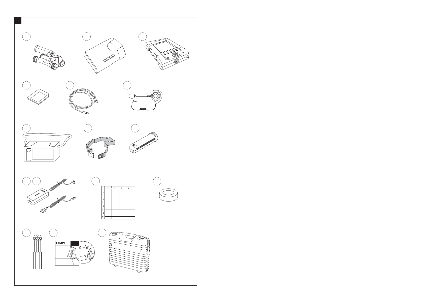
3. Items supplied
A complete PS 200 Ferroscan system consists of the following:
No. Designation
1 PS 200 S scanner
1 PSA 60 soft pouch
1 PS 200 M monitor
1 PSA 94 memory card
1 PSA 92 data cable
1 PSA 93 headset
with microphone
1 PSA 61 soft pouch
1 PSA 62 shoulder belt
2 PSA 80 batteries
2 PUA 80 chargers
2 Supply cords
2 PSA 10 reference grids
1 PUA 80 adhesive tape
1 PUA 70 marking pen
1 PSA 90 PC software
1 PS 200 toolbox
Accessories/spare parts
Item no. Designation
377654 PSA 10 reference grid set
340806 PUA 70 marking pen set
305141 PSA 91 memory card
319911 PSA 94 memory card
305142 PSA 92 data cable
319416 PSA 90 PC software
* PS 200 S scanner
* PS 200 S scanner set
377656 PSA 60 soft pouch
305144 PSA 63 hand strap
377658 PSA 62 shoulder strap
* PS 200 M monitor
377657 PSA 61 soft pouch
305143 PSA 93 headset with microphone
319362 PUA 90 adhesive tape
377660 PS 200 operating instructions
de/en/fr/it/es/nl/el/pt
377663 PS 200 operating instructions
en/ja/zh/ko/tr/pl/ru
377659 PS 200 toolbox
377472 PSA 80 battery
* PUA 80 charger
* Item number depends on country where item is ordered
Comments
*
Soft pouch for the scanner
*
Memory card (SD memory card)
USB cable
2.5 mm jack plug
Soft pouch for monitor
Belt for carrying the scanner and monitor in the soft pouches
NiMH rechargeable battery for the scanner or monitor
Charger for the PSA 80 battery
Supply cord for the PUA 80 charger *
Units in mm
3M Scotch tape 399 E, cotton tape for covering concrete
Set of 12 marking pens
PC software for the PS 200 Ferroscan system on CD-ROM
Plastic toolbox with insert for the PS 200 Ferroscan system
Comments
5 reference grids – mm
12 red marking pens
MMC card (128 MB)
SD card (at least 128 MB)
USB cable for transferring data
PC software on CD-ROM
Comprising PS 200 S scanner, PSA 80 battery, PSA 60
soft pouch, PSA 63 hand strap and operating instructions
in a cardboard box as replacement items
Comprising PS 200 S scanner, PSA 80 battery, PUA 80
charger, PSA 60 soft pouch, PSA 93 hand strap and
operating instructions in a Hilti toolbox
For the PS 200 S scanner
For the PS 200 S scanner
For carrying the PS 200 S scanner and PS 200 M monitor
Comprising PS 200 M monitor, PSA 80 battery, PSA 61
soft pouch and operating instructions in a cardboard box
as replacement items
For the PS 200 M monitor
For the PS 200 M monitor
Adhesive tape for attaching the reference grid to concrete
German, English, French, Italian, Spanish, Dutch, Greek,
Portuguese
English, Japanese, Chinese, Korean, Turkish, Polish,
Russian
With insert for the PS 200 system
For the PS 200 S scanner or PS 200 M monitor
For charging the PSA 80 battery
Page 6
38
en
4. Technical data
-NOTE-
For PUA 80 charger, refer to PUA 80 charger operating
instructions.
4.1 Environmental
Operating temperature range
Storage temperature
Relative humidity (operation)
Dust and water protection
(operation)
Impact resistance
(appliance in toolbox)
Dropping
Vibration (not in operation)
4.2 System scanning performance
For reliable scanning results, the following conditions
must be fulfilled:
– Concrete surface smooth and flat.
– Reinforcement not corroded.
– Reinforcement lying parallel to concrete surface.
– Concrete does not contain additives or components
with magnetic properties.
– Reinforcing bars lying within ±5° of right angle to
direction of scan.
– Reinforcing bars are not welded.
– Neighboring bars are of similar diameter.
– Neighboring bars are at a similar depth.
– Accuracy specifications are valid only for the first
layer of reinforcement.
– No interfering influences from external magnetic
fields or objects nearby with magnetic properties.
– Bars have relative magnetic permeability of 85-105.
– The scanner wheels are clean and free from sand or
grit.
– All 4 scanner wheels rotate on when scanner is
moved across the object to be scanned.
– Bars comply with one of the following standards
(depends on PS 200 Ferroscan system item number
printed on underside of original toolbox).
Item number Standard
377638, 377639,
377645 DIN 488
377642 ASTM A 615/
A 615M-01b
377643 CAN/CSA-G30,
18-M92
377644 JIS G 3112
228001 GB 50010-2002
-WARNING-
If any one or more of these conditions are not fulfilled,
accuracy and precision may be compromised.
The ratio of bar spacing:cover (s:c) is often a limiting
factor in resolving individual bars.
This is defined as:
4.2.1 Detection range, measurement range and
accuracy
Minimum bar spacing of 36 mm (1.4 inches) for resolving individual bars or bar spacing:cover (s:c) 2:1, whichever is greater. A minimum depth of 10 mm (0.4 inch)
is required for a depth reading.
Minimum distance of nearest reinforcing bar from starting point and finishing point of the scan (e.g. from edge
of reference grid): 30 mm (1.2 inch).
a. Imagescan and Blockscan
Rebar diameter given
Depth (mm)
20 40 60 80 100 120 140 160 180
6 ±2±3±3±4±50 X X X
8 ±2±2±3±4±50 0 X X
10 ±2 ±2 ±3 ±4 ±5 0 0 X X
12 ±2 ±2 ±3 ±4 ±5 ±10 0 X X
14 ±2 ±2 ±3 ±4 ±5 ±10 0 0 X
16 ±2 ±2 ±3 ±4 ±5 ±10 ±12 0 X
20 ±2 ±2 ±3 ±4 ±5 ±10 ±12 0 X
25 ±2 ±2 ±3 ±4 ±5 ±10 ±12 0 X
28 ±2 ±2 ±3 ±4 ±5 ±10 ±12 0 X
30 ±2 ±2 ±3 ±4 ±5 ±10 ±12 0 X
36 ±2 ±2 ±3 ±4 ±5 ±10 ±12 ±13 0
Spacing (s)
Surface
Depth of cover (c)
Bar diameter (DIN 488)
Wearing parts
The scanner wheels can be replaced by the user.
Item no. Designation
305152 PSW 200 S – 1 set of wheels
Refer to section 8.4 for instructions on removing and replacing the wheels.
Comments
4 wheels for the PS 200 S scanner, complete with hexagon
socket wrench (Allen key)
–10 °C to +50 °C
–20 °C to +60 °C
max. 90 %,
no condensation
IP54
EN 60068-2-29
EN 60068-2-32
MIL-STD 810 D
Origin/applicability of
the standard
European
Union
United States of
America
Canada
Japan
China
Page 7

Depth (mm)
20 40 60 80 100 120 140 160 180
#3 ±2 ±2 ±3 ±4 ±5 0 0 X X
#4 ±2 ±2 ±3 ±4 ±5 ±10 0 X X
#5 ±2 ±2 ±3 ±4 ±5 ±10 ±12 0 X
#6 ±2 ±2 ±3 ±4 ±5 ±10 ±12 0 X
#7 ±2 ±2 ±3 ±4 ±5 ±10 ±12 0 X
#8 ±2 ±2 ±3 ±4 ±5 ±10 ±12 0 X
#9 ±2 ±2 ±3 ±4 ±5 ±10 ±12 0 X
#10 ±2 ±2 ±3 ±4 ±5 ±10 ±12 0 X
#11 ±2 ±2 ±3 ±4 ±5 ±10 ±12 ±13 0
Depth (inch)
0.8 1.6 2.4 3.1 3.9 4.7 5.5 6.3 7.1
#3 ±0.1 ±0.1 ±0.1 ±0.15 ±0.2 0 0 X X
#4 ±0.1 ±0.1 ±0.1 ±0.15 ±0.2 ±0.4 0 X X
#5 ±0.1 ±0.1 ±0.1 ±0.15 ±0.2 ±0.4 ±0.5 0 X
#6 ±0.1 ±0.1 ±0.1 ±0.15 ±0.2 ±0.4 ±0.5 0 X
#7 ±0.1 ±0.1 ±0.1 ±0.15 ±0.2 ±0.4 ±0.5 0 X
#8 ±0.1 ±0.1 ±0.1 ±0.15 ±0.2 ±0.4 ±0.5 0 X
#9 ±0.1 ±0.1 ±0.1 ±0.15 ±0.2 ±0.4 ±0.5 0 X
#10 ±0.1 ±0.1 ±0.1 ±0.15 ±0.2 ±0.4 ±0.5 0 X
#11 ±0.1 ±0.1 ±0.1 ±0.15 ±0.2 ±0.4 ±0.5 ±0.5 0
Depth (mm)
20 40 60 80 100 120 140 160 180
#10 ±2 ±2 ±3 ±4 ±5 0 0 X X
#15 ±2 ±2 ±3 ±4 ±5 ±10 ±12 0 X
#20 ±2 ±2 ±3 ±4 ±5 ±10 ±12 0 X
#25 ±2 ±2 ±3 ±4 ±5 ±10 ±12 0 X
#30 ±2 ±2 ±3 ±4 ±5 ±10 ±12 0 X
#35 ±2 ±2 ±3 ±4 ±5 ±10 ±12 ±13 0
Depth (mm)
20 40 60 80 100 120 140 160 180
6 ±2±3±3±4±50 X X X
10 ±2 ±2 ±3 ±4 ±5 0 0 X X
13 ±2 ±2 ±3 ±4 ±5 ±10 0 X X
16 ±2 ±2 ±3 ±4 ±5 ±10 ±12 0 X
19 ±2 ±2 ±3 ±4 ±5 ±10 ±12 0 X
22 ±2 ±2 ±3 ±4 ±5 ±10 ±12 0 X
25 ±2 ±2 ±3 ±4 ±5 ±10 ±12 0 X
29 ±2 ±2 ±3 ±4 ±5 ±10 ±12 0 X
32 ±2 ±2 ±3 ±4 ±5 ±10 ±12 0 X
35 ±2 ±2 ±3 ±4 ±5 ±10 ±12 ±13 0
38 ±2 ±2 ±3 ±4 ±5 ±10 ±12 ±13 0
Depth (mm)
20 40 60 80 100 120 140 160 180
8 ±2±3±3±4±50 X X X
10 ±2 ±2 ±3 ±4 ±5 0 0 X X
12 ±2 ±2 ±3 ±4 ±5 ±10 0 X X
14 ±2 ±2 ±3 ±4 ±5 ±10 ±12 0 X
16 ±2 ±2 ±3 ±4 ±5 ±10 ±12 0 X
18 ±2 ±2 ±3 ±4 ±5 ±10 ±12 0 X
20 ±2 ±2 ±3 ±4 ±5 ±10 ±12 0 X
22 ±2 ±2 ±3 ±4 ±5 ±10 ±12 0 X
25 ±2 ±2 ±3 ±4 ±5 ±10 ±12 0 X
28 ±2 ±2 ±3 ±4 ±5 ±10 ±12 ±13 0
32 ±2 ±2 ±3 ±4 ±5 ±10 ±12 ±13 0
36 ±2 ±2 ±3 ±4 ±5 ±10 ±12 ±13 0
The value indicates typical accuracy of depth measurement (deviation from actual) in mm or inches, as applicable.
O: Bar is visible at this depth but no depth is calculated.
X: Bar cannot be detected at this depth.
Imagescan – rebar diameter not given.
Depth (mm)
20 40 60 80 100 120 140 160 180
6 ±3±3±4±6±80 X X X
8 ±3±3±4±6±80 0 X X
10 ±3 ±3 ±4 ±6 ±8 0 0 X X
12 ±3 ±3 ±4 ±6 ±8 ±12 0 X X
14 ±3 ±3 ±4 ±6 ±8 ±12 0 0 X
16 ±3 ±3 ±4 ±6 ±8 ±12 ±14 0 X
20 ±3 ±3 ±4 ±6 ±8 ±12 ±14 0 X
25 ±3 ±3 ±4 ±6 ±8 ±12 ±14 0 X
28 ±3 ±3 ±4 ±6 ±8 ±12 ±14 0 X
30 ±3 ±3 ±4 ±6 ±8 ±12 ±14 0 X
36 ±3 ±3 ±4 ±6 ±8 ±12 ±14 ±16 0
Depth (mm)
20 40 60 80 100 120 140 160 180
#3 ±3 ±3 ±4 ±6 ±8 0 0 X X
#4 ±3 ±3 ±4 ±6 ±8 ±12 0 X X
#5 ±3 ±3 ±4 ±6 ±8 ±12 ±14 0 X
#6 ±3 ±3 ±4 ±6 ±8 ±12 ±14 0 X
#7 ±3 ±3 ±4 ±6 ±8 ±12 ±14 0 X
#8 ±3 ±3 ±4 ±6 ±8 ±12 ±14 0 X
#9 ±3 ±3 ±4 ±6 ±8 ±12 ±14 0 X
#10 ±3 ±3 ±4 ±6 ±8 ±12 ±14 0 X
#11 ±3 ±3 ±4 ±6 ±8 ±12 ±14 ±16 X
Depth (inch)
0.8 1.6 2.4 3.1 3.9 4.7 5.5 6.3 7.1
#3 ±0.1 ±0.1 ±0.2 ±0.2 ±0.3 0 0 X X
#4 ±0.1 ±0.1 ±0.2 ±0.2 ±0.3 ±0.4 0 X X
#5 ±0.1 ±0.1 ±0.2 ±0.2 ±0.3 ±0.4 ±0.6 0 X
#6 ±0.1 ±0.1 ±0.2 ±0.2 ±0.3 ±0.4 ±0.6 0 X
#7 ±0.1 ±0.1 ±0.2 ±0.2 ±0.3 ±0.4 ±0.6 0 X
#8 ±0.1 ±0.1 ±0.2 ±0.2 ±0.3 ±0.4 ±0.6 0 X
#9 ±0.1 ±0.1 ±0.2 ±0.2 ±0.3 ±0.4 ±0.6 0 X
#10 ±0.1 ±0.1 ±0.2 ±0.2 ±0.3 ±0.4 ±0.6 0 X
#11 ±0.1 ±0.1 ±0.2 ±0.2 ±0.3 ±0.4 ±0.6 ±0.6 X
Depth (mm)
20 40 60 80 100 120 140 160 180
#10 ±3 ±3 ±4 ±6 ±8 0 0 X X
#15 ±3 ±3 ±4 ±6 ±8 ±12 ±14 0 X
#20 ±3 ±3 ±4 ±6 ±8 ±12 ±14 0 X
#25 ±3 ±3 ±4 ±6 ±8 ±12 ±14 0 X
#30 ±3 ±3 ±4 ±6 ±8 ±12 ±14 0 X
#35 ±3 ±3 ±4 ±6 ±8 ±12 ±14 ±16 X
Depth (mm)
20 40 60 80 100 120 140 160 180
6 ±3±3±4±6±80 X X X
10 ±3 ±3 ±4 ±6 ±8 0 0 X X
13 ±3 ±3 ±4 ±6 ±8 ±12 0 X X
16 ±3 ±3 ±4 ±6 ±8 ±12 ±14 0 X
19 ±3 ±3 ±4 ±6 ±8 ±12 ±14 0 X
22 ±3 ±3 ±4 ±6 ±8 ±12 ±14 0 X
25 ±3 ±3 ±4 ±6 ±8 ±12 ±14 0 X
29 ±3 ±3 ±4 ±6 ±8 ±12 ±14 0 X
32 ±3 ±3 ±4 ±6 ±8 ±12 ±14 0 X
35 ±3 ±3 ±4 ±6 ±8 ±12 ±14 ±16 X
38 ±3 ±3 ±4 ±6 ±8 ±12 ±14 ±16 X
39
en
Bar diameter (ASTM)Bar diameter (ASTM)
Bar diameter (CAN)Bar diameter (JIS)
Bar diameter (DIN 488)Bar diameter (ASTM)Bar diameter (ASTM)Bar diameter (CAN)Bar diameter (JIS)
Bar diameter (GB 50010-2002)
Page 8

40
en
Depth (mm)
20 40 60 80 100 120 140 160 180
8 ±3±3±4±6±80 X X X
10 ±3 ±3 ±4 ±6 ±8 0 0 X X
12 ±3 ±3 ±4 ±6 ±8 ±12 0 X X
14 ±3 ±3 ±4 ±6 ±8 ±12 ±14 0 X
16 ±3 ±3 ±4 ±6 ±8 ±12 ±14 0 X
18 ±3 ±3 ±4 ±6 ±8 ±12 ±14 0 X
20 ±3 ±3 ±4 ±6 ±8 ±12 ±14 0 X
22 ±3 ±3 ±4 ±6 ±8 ±12 ±14 0 X
25 ±3 ±3 ±4 ±6 ±8 ±12 ±14 0 X
28 ±3 ±3 ±4 ±6 ±8 ±12 ±14 ±16 X
32 ±3 ±3 ±4 ±6 ±8 ±12 ±14 ±16 X
36 ±3 ±3 ±4 ±6 ±8 ±12 ±14 ±16 X
Value indicates typical accuracy of depth measurement
(deviation from actual) in mm or inches, as applicable.
O: Bar is visible at this depth but no depth is calculated.
X: Bar cannot be detected at this depth.
b. Quickscan recording
Diameter is known.
Depth (mm)
20 40 60 80 100
6 ±1±1±2±4±5
8 ±1±1±2±4±5
10 ±1 ±1 ±2 ±4 ±5
12 ±1 ±1 ±2 ±4 ±5
14 ±1 ±1 ±2 ±4 ±5
16 ±1 ±1 ±2 ±4 ±5
20 ±1 ±1 ±2 ±4 ±5
25 ±1 ±1 ±2 ±4 ±5
28 ±1 ±1 ±2 ±4 ±5
30 ±1 ±1 ±2 ±4 ±5
36 ±1 ±1 ±2 ±4 ±5
Depth (mm)
20 40 60 80 100
#3 ±1 ±1 ±2 ±4 ±5
#4 ±1 ±1 ±2 ±4 ±5
#5 ±1 ±1 ±2 ±4 ±5
#6 ±1 ±1 ±2 ±4 ±5
#7 ±1 ±1 ±2 ±4 ±5
#8 ±1 ±1 ±2 ±4 ±5
#9 ±1 ±1 ±2 ±4 ±5
#10 ±1 ±1 ±2 ±4 ±5
#11 ±1 ±1 ±2 ±4 ±5
Depth (inch)
0.8 1.6 2.4 3.1 3.9
#3 ±0.05 ±0.05 ±0.1 ±0.15 ±0.2
#4 ±0.05 ±0.05 ±0.1 ±0.15 ±0.2
#5 ±0.05 ±0.05 ±0.1 ±0.15 ±0.2
#6 ±0.05 ±0.05 ±0.1 ±0.15 ±0.2
#7 ±0.05 ±0.05 ±0.1 ±0.15 ±0.2
#8 ±0.05 ±0.05 ±0.1 ±0.15 ±0.2
#9 ±0.05 ±0.05 ±0.1 ±0.15 ±0.2
#10 ±0.05 ±0.05 ±0.1 ±0.15 ±0.2
#11 ±0.05 ±0.05 ±0.1 ±0.15 ±0.2
Depth (mm)
20 40 60 80 100
#10 ±1 ±1 ±2 ±4 ±5
#15 ±1 ±1 ±2 ±4 ±5
#20 ±1 ±1 ±2 ±4 ±5
#25 ±1 ±1 ±2 ±4 ±5
#30 ±1 ±1 ±2 ±4 ±5
#35 ±1 ±1 ±2 ±4 ±5
Depth (mm)
20 40 60 80 100
6 ±1±1±2±4±5
10 ±1 ±1 ±2 ±4 ±5
13 ±1 ±1 ±2 ±4 ±5
16 ±1 ±1 ±2 ±4 ±5
19 ±1 ±1 ±2 ±4 ±5
22 ±1 ±1 ±2 ±4 ±5
25 ±1 ±1 ±2 ±4 ±5
29 ±1 ±1 ±2 ±4 ±5
32 ±1 ±1 ±2 ±4 ±5
35 ±1 ±1 ±2 ±4 ±5
38 ±1 ±1 ±2 ±4 ±5
Depth (mm)
20 40 60 80 100
8 ±1±1±2±4±5
10 ±1 ±1 ±2 ±4 ±5
12 ±1 ±1 ±2 ±4 ±5
14 ±1 ±1 ±2 ±4 ±5
16 ±1 ±1 ±2 ±4 ±5
18 ±1 ±1 ±2 ±4 ±5
20 ±1 ±1 ±2 ±4 ±5
22 ±1 ±1 ±2 ±4 ±5
25 ±1 ±1 ±2 ±4 ±5
28 ±1 ±1 ±2 ±4 ±5
32 ±1 ±1 ±2 ±4 ±5
36 ±1 ±1 ±2 ±4 ±5
Value indicates typical accuracy of depth measurement
(deviation from actual) in mm or inches as applicable.
c. Quickscan detection with depth measurement
Diameter is known.
Depth (mm)
20 40 60 80 100
6 ±2±2±3±4±5
8 ±2±2±3±4±5
10 ±2 ±2 ±3 ±4 ±5
12 ±2 ±2 ±3 ±4 ±5
14 ±2 ±2 ±3 ±4 ±5
16 ±2 ±2 ±3 ±4 ±5
20 ±2 ±2 ±3 ±4 ±5
25 ±2 ±2 ±3 ±4 ±5
28 ±2 ±2 ±3 ±4 ±5
30 ±2 ±2 ±3 ±4 ±5
36 ±2 ±2 ±3 ±4 ±5
Bar diameter (DIN 488)Bar diameter (ASTM) Bar diameter (ASTM) Bar diameter (GB 50010-2002)
Bar diameter (CAN)Bar diameter (JIS)Bar diameter (DIN 488) Bar diameter (GB 50010-2002)
Page 9

41
en
4.3 Specifications
Maximum scanning speed
Memory type
Memory capacity
Screen type/size
Screen resolution
Dimensions
Weight (with PSA 80 battery)
Depth (mm)
20 40 60 80 100
#3 ±2 ±2 ±3 ±4 ±5
#4 ±2 ±2 ±3 ±4 ±5
#5 ±2 ±2 ±3 ±4 ±5
#6 ±2 ±2 ±3 ±4 ±5
#7 ±2 ±2 ±3 ±4 ±5
#8 ±2 ±2 ±3 ±4 ±5
#9 ±2 ±2 ±3 ±4 ±5
#10 ±2 ±2 ±3 ±4 ±5
#11 ±2 ±2 ±3 ±4 ±5
Depth (inch)
0.8 1.6 2.4 3.1 3.9
#3 ±0.1 ±0.1 ±0.1 ±0.15 ±0.2
#4 ±0.1 ±0.1 ±0.1 ±0.15 ±0.2
#5 ±0.1 ±0.1 ±0.1 ±0.15 ±0.2
#6 ±0.1 ±0.1 ±0.1 ±0.15 ±0.2
#7 ±0.1 ±0.1 ±0.1 ±0.15 ±0.2
#8 ±0.1 ±0.1 ±0.1 ±0.15 ±0.2
#9 ±0.1 ±0.1 ±0.1 ±0.15 ±0.2
#10 ±0.1 ±0.1 ±0.1 ±0.15 ±0.2
#11 ±0.1 ±0.1 ±0.1 ±0.15 ±0.2
Depth (mm)
20 40 60 80 100
#10 ±2 ±2 ±3 ±4 ±5
#15 ±2 ±2 ±3 ±4 ±5
#20 ±2 ±2 ±3 ±4 ±5
#25 ±2 ±2 ±3 ±4 ±5
#30 ±2 ±2 ±3 ±4 ±5
#35 ±2 ±2 ±3 ±4 ±5
Depth (mm)
20 40 60 80 100
6 ±2±2±3±4±5
10 ±2 ±2 ±3 ±4 ±5
13 ±2 ±2 ±3 ±4 ±5
16 ±2 ±2 ±3 ±4 ±5
19 ±2 ±2 ±3 ±4 ±5
22 ±2 ±2 ±3 ±4 ±5
25 ±2 ±2 ±3 ±4 ±5
29 ±2 ±2 ±3 ±4 ±5
32 ±2 ±2 ±3 ±4 ±5
35 ±2 ±2 ±3 ±4 ±5
38 ±2 ±2 ±3 ±4 ±5
Depth (mm)
20 40 60 80 100
8 ±2±2±3±4±5
10 ±2 ±2 ±3 ±4 ±5
12 ±2 ±2 ±3 ±4 ±5
14 ±2 ±2 ±3 ±4 ±5
16 ±2 ±2 ±3 ±4 ±5
18 ±2 ±2 ±3 ±4 ±5
20 ±2 ±2 ±3 ±4 ±5
22 ±2 ±2 ±3 ±4 ±5
25 ±2 ±2 ±3 ±4 ±5
28 ±2 ±2 ±3 ±4 ±5
32 ±2 ±2 ±3 ±4 ±5
36 ±2 ±2 ±3 ±4 ±5
Value indicates typical accuracy of depth measurement
(deviation from actual) in mm or inches as applicable.
d. Quickscan detection
Depth measurement is typically accurate to within ±10 %
of the effective depth.
4.2.2 Accuracy of bar diameter measurement
±1 standard diameter when rebar spacing: depth of cover
≥2 :1. Bar diameter measurement is possible only at
depths of up to 60 mm.
4.2.3 Accuracy of rebar location
Relative bar center measurement accuracy (all modes),
typical: Typically ±3 mm or typically ±0.1 inch relative to
the measured position, when the bar spacing: depth of
cover ≥1.5 :1 .
Bar diameter (ASTM)Bar diameter (ASTM)Bar diameter
(CAN)
Bar diameter (JIS)
Bar diameter (GB 50010-2002)
PS 200 M monitor
-Removable SD card, max. memory
card size: 1 GB
At least 150 Imagescans or 75 Quick-
scans (total 2250 m), plus up to
15 minutes of speech with 32 MB
card.
LCD/115 × 86 mm
320 × 240 pixels/16 gray scales
264 × 152× 57 mm
1.40 kg
PS 200 S scanner
0.5 m/s
Built-in data flash memory
9 Imagescans plus up to 30 m
of recorded Quickscan
(max. 10 scans)
LCD/50 × 37 mm
128 × 64 pixels
260 × 132× 132 mm
1.40 kg
Page 10
42
en
5. Safety rules
5.1 General safety rules
In addition to the safety rules listed in the individual sections of these operating instructions, the following rules
must be strictly observed at all times.
5.2 Intended use
The appliance is intended to be used for locating reinforcing bars in concrete, measuring depth of concrete
cover and estimating the diameter of the bars in the
uppermost layer in accordance with the specifications
detailed in section 4.
● Dangerous situations may occur when the appliance
is either not used for its intended purpose or is used
incorrectly by untrained personnel.
● To minimize the risk of injury, use only genuine Hilti
accessories and replacement parts.
● Tampering with the appliance or modification of its
parts is not permissible.
● Take notice of the instructions regarding use, care and
maintenance given in the operating instructions.
● Do not deactivate any safety devices. Do not remove
any information or warning labels.
● Have the appliance repaired only at a Hilti service cen-
ter.
● In particularly critical situations where measurements
have safety and structural stability implications, always
check results by removing material from the surface
of the structure and physically checking the position,
depth and diameter of reinforcement at key positions.
● When drilling at or near to a bar indicated by the appli-
ance, never drill deeper than the bar depth indicated.
5.3 Work area safety
● Ensure there are no objects in the area of work with
which you could injure yourself.
● Keep other people away from the work area, especially
children.
● Avoid working in awkward body positions.
● Wear footwear with a non-slip tread and ensure you
always employ a stable standing position.
● Avoid leaning when working on ladders. Always work
from a secure position and stay in balance.
● Use the appliance only within its defined performance
limits.
● Check with a qualified person that it is safe to drill at
a specified point before beginning drilling.
● Never use the appliance in areas where there is dan-
ger of explosion.
● Ensure the toolbox is properly secured during trans-
port and does not pose a risk of injury.
Minimum battery life
(with PSA 80 battery)
Automatic power-off
Backup battery type/life
PC connection
Headset connection
Scanner-monitor data interface
Scanner-monitor data transfer time
Infrared range
Infrared output power
4.4 Technical data for PSA 80 battery
Battery type NiMH
Nominal voltage 9.6 V nominal
Capacity 2000 mAh nominal
Dimensions 42 × 46 ×46 mm or
5.6 × 1.8× 1.8 in
Weight 0.3 kg or 0.7 lb
Min. no. charge cycles Typically 500
8 hours under typical conditions
5 min. after last press of a button
Lithium/10 years (typically)
--
-Infrared
<16 s for 9 images, <2 s for 1 image
0.3 m (typically)
Max. 500 mW
8 hours under typical conditions
Set by the user
Lithium/10 years (typically)
USB V 1.1
2.5 mm mini jack
Infrared
<16 s for 9 images, <2 s for 1 image
0.3 m (typically)
Max. 500 mW
Page 11
43
en
5.3.1 Electromagnetic compatibility
Although the appliance fulfills the requirements of the
relevant regulations, Hilti cannot rule out the possibility that:
● Other equipment (e.g. airborne navigation systems,
medical equipment) will be disturbed by the PS 200
or
● That this disturbance will lead to a malfunction of the
PS 200. In such cases or in case of any uncertainty,
control measurements must be carried out.
5.4 General safety measures
5.4.1 Mechanical
● Check the appliance for possible faults before use.
In case of a fault, have the appliance repaired by Hilti
Service.
● If the appliance is dropped or subjected to an impact,
its accuracy must be subsequently checked.
● Check the accuracy of the appliance each time before
use.
● When moving the appliance between temperature
extremes, allow it to become acclimatize to the new
temperature before use.
● Even though the appliance is protected against the
ingress of moisture, always wipe it dry before storing
it in the toolbox.
5.4.2 Electrical
● Avoid shorting the battery terminals. Such electrical
shorting can cause fire.
● Ensure that the exterior surfaces of the battery are
clean and dry before connecting it to the charger.
● Use only the battery specified in these operating
instructions.
● Ensure that the battery is safely disposed of at the end
of its life.
● When transporting the appliance or storing it for a
longer period of time, remove the battery. Before
reusing it, inspect the battery for any signs of leakage or damage.
● To avoid environmental pollution, the battery must be
disposed of in accordance with country-specific regulations. In case of doubt, contact Hilti.
5.4.3 Liquids
-WARNING-
A corrosive liquid can leak from defective batteries.
Avoid contact with this liquid. Should the liquid come
into contact with the skin, wash the area affected liberally with soap and water. In case of contact with the
eyes, rinse them immediately with water and consult a
doctor.
5.5 Requirements to be met by the user
● The appliance is intended for professional users.
● The appliance may be used, maintained and cared for
only by authorized, personnel who have recieved
instruction in its use. This personnel must be specially
instructed in the hazards associated with the appliance.
● Always concentrate on your work. Always think care-
fully about what you are doing. Do not use the appliance if you are unable to concentrate.
● Do not use the appliance if it appears to be defective
in any way.
● If you are unsure of any scan results, consult a Hilti
specialist before proceeding.
● Observe all warning and information messages dis-
played by the scanner and monitor.
5.6 Scanning requirements and limitations
● Always check the accuracy of the appliance before
commencing work on structures where measurements
have safety and structural stability implications. Scan
a reinforcing bar of known location, depth and diameter and check the results against the accuracy specifications.
● Do not use the PS 200 S scanner if the wheels do not
turn freely or appear to be worn. Contact Hilti for repair
information. Additionally, you can clean or replace the
wheels – refer to section 8.
● Check the settings made in the appliance before use.
● Apply only light pressure to the scanner when mov-
ing it across the surface.
● Reinforcement that lies beneath the uppermost layer
of reinforcement may not be detected.
● Remove all items such as rings, bracelets, etc. before
commencing scanning.
Page 12

6.2 PSA 91/PSA 94 memory card
Insert the memory card in the slot provided on the back
of the monitor.
To remove the memory card, press it once. The card will
release from the slot. It can now be easily gripped and
removed.
-WARNING-
Although the memory card is of the SD or Multimedia
Card type, standards vary between different manufacturers. To help ensure data security and integrity, memory cards supplied by Hilti should be used. Data may be
irretrievably lost if memory cards other than those supplied by Hilti are used.
-WARNING-
Do not remove the memory card during operation or
when the monitor is switched on. Removing the card at
such a time may result in data loss. Only remove the
card when the monitor is switched off.
-NOTE-
When the memory card is removed, the monitor will automatically revert to using the 3 MB internal memory. Data
will then be saved in this memory under a project with
the name "Prj00001" until a memory card is inserted in
the monitor. When a memory card is inserted and the
monitor switched on, all data in internal memory will be
transferred to the memory card automatically.
6.2.1 Using memory cards
With monitors with item no. 319281, only memory cards
of the MMC type may be used (up to a max. capacity of
128 MB). With monitors with item no. 31225, memory
cards of the MMC and SD types may be used (up to a
max. capacity of 1 GB).
-WARNING-
SD memory cards cannot be used with the old-type
monitor.
-NOTE-
The item no. can be found on the type identification plate
on the underside of the monitor.
44
en
6. Operation
6.1 PSA 80 battery
Charge both batteries using the PUA 80 chargers. Full
instructions are contained in the PUA 80 charger operating instructions. Before first use, the batteries must
be charged for 14 hours continuously.
6.1.1 Inserting and removing the battery
Check that the battery is correctly aligned with the scanner or monitor as shown below.
Scanner – With the battery end cap facing you, the large
groove on the battery should be on the left.
Monitor – With the battery end cap facing you, the large
groove on the battery should be on the right.
Push the battery into the opening as far as it will go. Turn
the end cap clockwise until it slots into place and snaps
tight. To remove the battery, turn the end cap anti-clockwise as far as it will go. Withdraw the battery from the
scanner or monitor.
-CAUTION-
The battery should slide easily into the scanner or monitor. Do not force the battery into the scanner or monitor as this may damage the battery itself or the scanner
or monitor casing.
-WARNING-
Do not remove the battery during operation or when the
monitor is switched on. Removing the battery at such
a time may result in data loss. Remove the battery only
when the monitor is switched off.
P
S
2
0
0
F
e
r
r
o
s
c
a
n
-CAUTION-
Take care to ensure that
the card is inserted the
right way round.
Page 13

45
en
7. Operation
7.1 Carrying and using the system
The scanner can be used without the monitor for scanning, or the monitor can be carried in the PSA 61 soft
pouch on the PSA 60 shoulder belt. The first option is
advantageous when working in areas that are difficult
to access and maximum mobility is required, such as
on a scaffold or ladder. When the scanner memory is
full (9 Imagescans made, 1 complete Blockscan or 30 m
of Quickscan have been recorded), the user must return
to the monitor to transfer the data. The monitor can be
kept nearby (e.g. at the foot of the scaffold, in a vehicle,
in the site office etc.). When the user intends to make
more scans than the scanner is capable of storing in its
memory and wishes to avoid repeated journeys to the
monitor, the monitor can be attached to a belt or carried
using the shoulder strap supplied.
-CAUTION-
The temperature inside a vehicle that is left exposed to
the heat of the sun can easily exceed the maximum storage temperature for the PS 200. Damage to one or more
components of the PS 200 may occur if it is stored in
temperatures exceeding 60 °C or 158 °F.
7.2 Operating the scanner
7.2.1 Control panel and screen layout
1 – Arrow buttons
2 – Confirm button
3 – On/off button
4 – Cancel button
5 – Record button
1 – Menu area. Functions that can be selected using the
Arrow and Confirm buttons
2 – Status information – information such as battery
level, memory status
3 – Variable area – information displayed is user feed-
back – e.g. measuring mode, bar depth, scan progress
etc.
7.2.2 Switching on and off
To switch the scanner on or off, press and hold the On/off
button momentarily.
The scanner can be switched off only when it is in the
main menu.
7.2.3 Main menu
The system always starts in the main menu. All scanning
functions and set-up options are selected here. The battery charge status is displayed at the top of the screen
together with the memory status. The various scan modes
and settings menus are displayed as icons on the left
side of screen. Use the Arrow buttons to toggle between
these options. The Confirm button selects the option.
Quickscan – The remaining memory for Quickscan
recording is shown at the top of the screen in meters or
feet (depending on the scanner type and units set).
Imagescan – The number of Imagescans in the scanner,
up to a maximum of 9, is shown at the top of the screen.
Blockscan – The number of Imagescans in the scanner,
up to a maximum of 9, is shown at the top of the screen.
Toggle up or down in options or
values.
Confirms a value or a selection.
Cancels an input or moves back
one screen.
Starts or stops a recording.
1
2
3
4
5
2
13
Page 14

46
en
Settings – Sets various parameters and deletes all scans
held in memory.
7.2.4 Settings
Use this menu to set general parameters and to delete
scans from the scanner that have not been transferred
to the monitor.
Upon entering Settings, the following screen is displayed:
Use the Arrow buttons to toggle between options, Con-
firm to select an option and Cancel to return to the main
menu.
7.2.4.1 Set display backlight
Sets the display backlight. Use the Arrow buttons to toggle between options. Use the Confirm button to select
the desired option and then press the Cancel button to
return to the settings menu.
Backlight permanently on
Backlight permanently off
Backlight timed – switches off 5 minutes after the last
press of a button. Backlight activates automatically on
next press of a button.
7.2.4.2 Set volume
Sets the volume level of the audible signal during scanning. Use the Arrow buttons to toggle between options.
Use the Confirm button to select the desired option and
then press the Cancel button to return to the settings
menu.
7.2.4.3 Set units
Sets the units used during measurement. This is available only in units with item no. 377642. Use the Arrow
buttons to toggle between options. Use the Confirm but-
ton to select the desired option and then press the Cancel button to return to the Settings menu.
metric (mm or m, as appropriate)
imperial (inches or feet, as appropriate)
7.2.4.4 Delete data
Deletes all data contained in the scanner. This function
can be accessed only if data is contained in memory. If
data is contained in memory, the bar that appears next
Page 15

47
en
to the diskette symbol is filled. If not, the bar is shown
empty.
-WARNING-
This may result in permanent data loss. Data that has
not been transferred to the monitor will be permanently
deleted.
Press the Down arrow button and then the Confirm
button to delete data. Alternatively, press the Cancel
button to return to the Settings menu.
7.2.5 Quickscan
Quickscan can be used to quickly detect bar positions
and depths that are then subsequently marked on the
surface. This is procedure is named Quickscan detection.
Accurate depth measurement is another Quickscan function in which values for bar diameter and bar spacing
must be previously entered.
Alternatively, the data can be recorded and evaluated on
the monitor or in the PC application.In this way, the average depth of cover over the reinforcement over large
stretches of the surface can be easily determined. This
is termed Quickscan recording.
-CAUTION-
The scanner only detects reinforcing bars that lie perpendicular to the direction of travel. Bars that lie parallel
to the direction of travel will not be detected. Therefore,
ensure that the object is scanned in both the horizontal
and vertical directions.
An incorrect depth may be calculated for bars that lie diagonal to the direction of travel.
Switch on the scanner. The Quickscan icon is automatically the first selected.
Select Quickscan from the main menu.
The Quickscan screen is then displayed.
1 – Bar depth
2 – Distance traveled
3 – Signal strength
4 – Settings: minimum depth, scan direction, bar
diameter, bar spacing
7.2.5.1 Quickscan detection
Move the scanner over the surface. Reinforcing bars that
lie perpendicular to the direction of travel will be detected. The distance covered by the scanner is recorded.
When approaching a reinforcing bar, the signal strength
increases and depth values may appear in the display.
When at the center of a reinforcing bar:
– the red LED lights,
– the scanner beeps,
– the signal strength bar is at maximum,
– and the approximate depth of the bar is indicated
(lowest depth value indicated = center of the bar).
The bar is positioned along the center line of the scanner
and may be marked on the surface using a PUA 70 marker. The accuracy of the depth measurement can be increased
by switching to accurate depth measurement measuring
mode. Please refer to section 7.2.5.2.
This symbol may appear when the scanner is moved over
the surface. It indicates that the scanner is being moved
too quickly to be able to process all signals generated. The
maximum speed is 0.5m/s (20 inches/sec.). If the symbol
appears during Quickscan detection, press Confirm and
scan again.
2
4
3
1
Page 16

48
en
7.2.5.2 Quickscan with accurate depth
measurement
The measuring mode "Quickscan with accurate depth
measurement" is selected by pressing the Confirm but-
ton.
The diameter must be known and previously entered.
In addition, the value for the spacing between bars must
also be entered if it lies between >36 and <120 mm.
-NOTE-
Bar spacing of 36 mm or less cannot be measured.
This can be calculated automatically using the Quickscan
detection function by searching for the center of the bar
and pressing the red Record button when the scanner
is over the mid point of the bar. Next, search for the mid
point of the next bar and again press the Record but-
ton. Bar spacing is then calculated automatically and
recorded. If the spacing is known, the value can also be
entered manually.
After setting the bar diameter and bar spacing, the scanning procedure is identical to the procedure described
at 7.2.5.1.
7.2.5.3 Quickscan recording
To record the position and depth of all reinforcing bars
detected, place the scanner on the surface and use
Quickscan detection to find a position where there are
no bars present. Mark the starting point with a PUA 70
marker and press the Record button. The diskette symbol appears on the screen, indicating that the scanner
is recording data. Move the scanner over the surface.
At the end of the scan, take care to ensure that the end
point is not directly over a rebar. To stop recording, press
Record again. Use a PUA 70 marker to mark the end of
the stretch that has been scanned.
-NOTE-
Reinforcing bars that lie perpendicular to the direction
of travel will be detected and automatically recorded.
Ensure that the settings are correctly set before beginning recording.
-WARNING-
Always carry out an Imagescan prior to Quickscan recording in order to:
– establish the direction of the uppermost layer of rein-
forcement,
– minimize the risk of measuring on a spliced bar,
– and immediately see if there are any ferrous materials
in the concrete that may affect the accuracy of the result.
-CAUTION-
Do not press Record before placing the scanner at the
point where the scanning should begin. Failure to do
this may result in incorrect or misleading measurements.
Up to 30 m (98 ft) can be recorded before it is necessary to transfer the data to the monitor. It is also possible to record several separate stretches (max. 10) that
add up to a maximum of 30 m.
Page 17

49
en
-WARNING-
Do not remove the scanner from the surface before stopping the recording or setting a marker. Failure to do this
may result in incorrect or misleading measurements. For
information on setting a marker, refer to section 7.2.5.5.
This symbol may appear when the scanner is being
moved over the surface. It indicates that the scanner is
being moved too fast and it is unable to process all the
signals generated. The maximum scanning speed is
0.5 m/s. If the symbol is displayed while recording a
Quickscan, press the Confirm button. You will need to
begin the recording operation again from the original
starting point or from where the last marker was set.
The data may be transferred to the monitor. Refer to section 7.4.
7.2.5.4 Quickscan settings
The Quickscan settings are shown on the left hand side
of the display. The settings can be made before making
a Quickscan or a Quickscan with accurate depth measurement. Use the Arrow buttons and Confirm to access
the setting.
Minimum depth
Use this setting when scanning a surface and looking
specifically for bars that are located above a certain
depth. For example, if checking for 40 mm minimum
depth of cover, set the value to 40 mm. (For quality
assurance measurements add an extra 2 mm to account
for any accuracy limitations). The LED will light only if
a reinforcing bar lying within 40 mm of the surface is
detected.
Select the minimum depth function using the Arrow but-
tons and then press Confirm.
Setting minimum depth
Minimum depth function disabled
When the value is set to 0, the function is deactivated
and appears as above. Enter the required minimum depth
using the Arrow buttons. Press Confirm to make the setting. The system returns to the main menu.
Scan direction
This setting is used to set the direction in which Quickscan recording is performed. Although it has no direct
effect on any measurement values subsequently contained in the monitor or PC application, it helps to match
the resulting chart and depth values in the PC application with the actual structure surface. The scan direction will be saved with all Quickscan recordings.
Select the direction in which the scan is to be performed
and press Confirm.
Bar diameter
This setting must be made in order to be able to measure depth of cover accurately, or to allow values to be
recorded. Only then can depth be measured accurately.
Select the Bar Diameter function using the Arrow but-
tons. Press Confirm.
If no bar diameter is selected, the scanner will calculate
the depth as though the average bar diameter of the relevant standard setting range were set.
Page 18

50
en
Standard ∅
DIN 488 16 mm
ASTM A 615/A 615M-01b # 7
CAN/CSA-G30, 18-M92 C 20
JIS G 3112 D 22
GB 50012-2002 18 mm
-NOTE-
The bar diameter previously set will be stored in the
scanner after it has been switched off.
Bar spacing
Please refer to 7.2.5.2.
7.2.5.5 Setting a marker
When recording, the surfaces of many structures contain obstacles that prevent the scan being recorded
without lifting the scanner from the surface. Examples
of such obstacles are piers or columns in a wall, door
openings, expansion joints, corners etc.
If an obstacle is encountered, a marker may be set. This
interrupts the scan and allows the user to safely remove
the scanner from the surface, place it beyond the obstruction and then continue scanning. It also indicates where
certain objects are located within a scan, providing additional information for referencing the scan data to the
actual surface.
To set the marker press and hold Confirm, whilst in
recording mode. The diskette symbol will be crossed
out, indicating that recording has been suspended and
a marker has been set.
Then lift the scanner from the surface whilst still holding the Confirm button depressed. If necessary, mark
the position on the surface using a PUA 70 marker. Place
the scanner back on the surface beyond the obstacle,
release Confirm and continue scanning. The marker will
be shown as a vertical line in the scan data when viewed
on the monitor or in the PC application.
-CAUTION-
De to interruption of the recorded signal, scanning results
are less accurate immediately before and after the point
where a mark is made.
7.2.6 Imagescan
Imagescan is used to create an image of the reinforcement layout. The depth and diameter of the bars can be
determined.
Firstly, a PSA 10 or PSA 11 reference grid has to be fixed
to the wall. Use the adhesive tape supplied. This tape is
designed specifically for sticking to concrete structures
and can be torn off the roll by hand at the correct length.
For most surfaces, a 100 mm (4 inch) piece of tape at
each corner is adequate to secure the grid. Particularly
moist or dusty surfaces may require a length of tape
along each side of the grid.
Alternatively, a grid can be marked directly on the surface. Using a straight edge (such as a piece of wood) as
a guide, mark a 4 ×4 grid with 150 mm spacing between
the parallel lines.
Switch on the scanner. Move to the Imagescan symbol.
The battery level is displayed together with the number
of Imagescans currently held in the memory out of a
maximum of 9.
Select Imagescan from the main menu.
The Imagescan screen is displayed.
A representation of the grid appears on the screen with
a suggested starting point. This is always upper left and
will suffice for most scans. Image data will only be generated for areas of the grid that have been scanned both
vertically and horizontally. In some cases, obstacles on
the scan area may prevent this (e.g. a pipe penetrating
a beam). The starting point can then be changed to optimize the area scanned in such a case. Use the Arrow
buttons to change the starting point.
Page 19

51
en
Place the scanner on the grid at the starting point shown
by the blinking arrow. Ensure the alignment marks on the
scanner are aligned correctly with the grid as shown below.
-NOTE-
Incorrect alignment of the scanner on the grid may lead
to the bar positions being incorrect on the generated
image.
Press Record and move the scanner along the first row.
Progress when scanning is shown by a thick black line
which advances on the display as the scanner is moved
over the surface.
The scanner will emit a double beep at the end of the
row, automatically stopping the recording. Repeat the
process for each row, observing the prompts on the
scanner display telling you to begin a new line.
150
150
5
1
2
Æ
PS 200 S Ferroscan
Æ
PS 200 S Ferroscan
When all rows are complete, scan the columns in a similar way.
The recording of any row or column may be interrupted before reaching the end by pressing Record again.
This may be required if an obstacle prevents scanning
of the full path. Similarly, an entire row or column may
be skipped by starting and stopping the recording without running the scanner over the grid.
Æ
PS 200 S Ferroscan
Æ
PS 200 S Ferroscan
Æ
PS 200 S Ferroscan
Æ
PS 200 S Ferroscan
Page 20

52
en
Note that no image will be created for areas of the grid
that are not scanned in both directions.
It is possible to repeat the previous row or column by
pressing Cancel. This may be necessary if the user is
not sure that the scan field has not been followed accurately. Pressing Cancel a second time aborts the scan
and returns to the main menu.
This symbol may appear when the scanner is being
moved over the surface. It indicates that the scanner is
being moved too quickly to allow it to process all the
signals generated. The maximum speed is 0.5 m/s or
20 inch/s. If this symbol appears, press Confirm and
repeat the row or column you were scanning. In all cases, move the scanner more slowly over the surface.
When the scan is complete, press the Confirm button
to return to the main menu. The data may be transferred
to the monitor for viewing and evaluation. Please refer
to section 7.4.
-CAUTION-
Pressing the Cancel button causes the recorded Imagescan to be deleted. The screen then returns to the main
menu.
7.2.7 Blockscan
Blockscan automatically stitches Imagescans together
to give an impression of the reinforcement layout over
a large area. The exact bar position, depth and diameter can also be determined on the monitor by selecting
each Imagescan individually.
Attach the reference grid in the same way as when making an Imagescan. Mark the edge(s) for the transition
to the next grid using a PUA 70 marker, as shown below.
Switch on the scanner. Move to the Blockscan symbol.
The battery level is given, together with the number of
Imagescans currently held in the memory out of a maximum of 9.
To begin, select Blockscan from the main menu.
A representation of a Blockscan is shown on the screen.
Each square represents an Imagescan. Up to 3 ×3 Imagescans can be scanned. Select the position of the first
Imagescan that you will make in the series using the
Arrow buttons. Press Confirm to begin the first Image-
scan. Note that the coordinates of any points on the
Blockscan will be referenced from the upper left corner.
Refer to the previous section for details on how to carry out the Imagescan. When the Imagescan is complete,
the system returns to the Blockscan screen.
150
150
300
450
600
300 450 600
5 6 7 8
1
2
3
4
Page 21

53
en
The completed Imagescan is shown shaded. Attach a
new grid to the wall so that the edges of the reference
grid overlap and the scan areas are aligned as shown in
the diagram.
Select the location of the next Imagescan and repeat
the scanning process. Completed Imagescans may be
repeated by simply reselecting the area to scan and performing the Imagescan process. The data will be overwritten. When sufficient Imagescans have been made,
or when all nine are complete, press Cancel to return
to the main menu and transfer the data to the monitor.
Please refer to section 7.4.
-CAUTION-
Pressing the Cancel button twice causes the recorded
Imagescan to be deleted. The screen then returns to the
main menu.
7.2.8 Error messages from the scanner when
starting or scanning
Error messages may be displayed graphically on the
scanner. Generally, a stop symbol indicates a fatal error
with the scanner. In this case, the scanner requires to
be serviced at a Hilti repair center.
or
One of these symbols may be displayed immediately
after the scanner is switched on. They indicate a possible electronic fault. Switch the scanner off and then back
on again. If the error message appears again, the appliance will need to be sent to Hilti for repair.
An exclamation symbol indicates either an error caused
by the operator or an error that can be solved by the
operator.
150
150
300
450
600
300 450 600
5 6 7 8
1
2
3
4
150
150
300
450
600
300 450 600
5 6 7 8
1
2
3
4
This symbol may appear either when trying to enter the
Imagescan or Blockscan scanning mode, when trying
to begin a new Imagescan within Blockscan scanning
mode or when trying to start Quickscan recording. It
indicates that the memory allocated for the operation is
full and that no more data can be stored. In this situation, the data must either be transferred to the monitor
or deleted from scanner memory.
-WARNING-
Deleting the scanner memory may result in permanent
data loss. Data that has not been transferred to the monitor will be permanently deleted.
This symbol may appear during any type of scanning
when the Scanner is being moved over the surface. It
indicates that the Scanner is being moved too quickly
to allow it to process all the signals generated. The maximum speed is 0.5m/s or 20 inches/s.
If the symbol appears during Quickscan detection, press
Confirm and repeat the scan. During Quickscan recording, press Confirm. You will need to begin the recording operation again from the original starting point or
from where the last marker was set. During Imagescan,
press Confirm and repeat the row or column previous-
ly scanned. In all cases, move the scanner more slowly over the surface.
This symbol may appear if the scanner has been moved
in the wrong direction during scanning, e.g. you begin
scanning from right to left but during the scan move the
scanner toward the right. The warning does not appear
immediately, but only when moved 15 cm or more in
the wrong direction.
7.3 Operating the monitor
The monitor provides extensive data storage capability,
the ability to analyze scan data at the site where it was
collected and also to add voice records to scans.
Page 22

54
en
1 – Display
2 – "Soft" buttons – used to select menu options.
3 – Arrow buttons – used to move the cursor around
the screen or adjust values.
4 – On/off button
5 – Headset connection (at the side)
6 – Battery (at the side)
7 – Compartment containing USB connection and mem-
ory card (at the side)
7.3.1 Switching on and off
To switch the monitor on, press and hold the On/off button for 1 second. The monitor will display a boot-up
screen for about 15 seconds until it is ready for use. To
switch off, press and hold the On/off button for about
1 second. The system switches itself off.
7.3.2 General screen layout
Status bar
Battery level. All 5 blocks filled indicates that the battery
is fully charged. Warnings will appear when the level
reaches the last block and about 15 minutes and 5 minutes before the battery is totally exhausted. Thereafter,
the system will beep every two minutes until it is switched
off. If the monitor is switched off when battery power is
low, it will not be possible to switch it back on until the
battery has been recharged.
– Memory card
Indicates the memory source being used and the free
space available. A full bar indicates that memory is full.
When the memory card is inserted, it is used as the
memory source and the symbol appears as above. If the
card is removed, the monitor uses its own limited-capacity internal memory which provides space for a minimum of 20 scans. The symbol then changes to the following:
– Internal memory
– Connected to PC for data transfer
– Connected to PC for data transfer, memory card
removed: no data transfer possible.
– Infrared symbol – indicates the status of the
infrared port.
– Ready
– Data backup
– Transmitting/receiving data
– Voice record available
– Bar diameter fixed
– Scan calibrated (Imagescan only)
Information bar
Information about the items currently shown in the main
display area appears here. This varies with the type of
scan being viewed.
Menu area
The menu items differ according to the operation being
carried out, with the menu title being displayed at the
top. Each item or command is executed by pressing the
associated soft button.
Main display area
Scanned images, settings and project information are
displayed here.
7.3.3 Setup
General settings for the monitor are made here. Use the
soft buttons to access a menu item and the arrow buttons to move between options in an item and to select
values.
Main display area
Menu
area
Status
bar
Information bar
Page 23

55
en
Monitor Volume sets the volume for the acoustic signal
(beep).
Headset Volume sets the headset volume level.
Contrast sets the level of the screen contrast.
Backlight sets the brightness of the screen backlight.
To access further settings press More…
Use the soft buttons to access a menu item and the arrow
buttons to move between options in an item and to select
values.
Date/Time sets the correct date and time. This is used
for scan management and naming purposes.
Lang./Unit sets the language and the units of distance
to be used.
Power Mode sets the various power saving features on
the monitor. Backlight Off sets the time until the backlight is switched off after the last press of a button. Stand-
by sets the length of time until the system goes into
standby – the screen is inactive but reappears instantly at the next press of a button or when the scanner is
brought close to transfer data. Power Off sets the length
of time until the monitor automatically powers down.
When you have completed your selection, press Done
to return to the previous menu.
7.3.4 Project
Scans are organized on the monitor under project names.
Scans from objects belonging to different customers,
locations or jobs can thus be meaningfully differentiated.
The project currently selected is shown. The number of
the current project and the total number of projects contained on the memory card or in internal memory are
shown in the information bar. Use the left/right arrow
buttons to select a different project.
View Scans… allows the scans contained in a project
to be listed, opened for analysis, moved and deleted.
Create creates a new project.
Edit allows text to be entered.
All Projects provides an overview of all projects.
7.3.4.1 Viewing scans
Press View Scans…
All scanned images from a project are shown in the form
of a thumbnail view complete with names and the date
and time of scanning. Use the up and down arrow buttons to move up and down the list.
Open opens the highlighted scan.
More… accesses further scan management functions.
Page 24

56
en
Use Select All or Select to select scans for moving or
deletion.
Select All selects all the scans in the project.
Select selects the scan currently highlighted and may
also be used to select multiple scans.
Move… moves the selected scans to another project of
your choice.
Delete deletes the selected scans.
-NOTE-
Move and Delete are unavailable until one or more scans
have been selected.
Date/Time and Serial Number allow the date and time
of the scans in the project, or the serial number of the
scanner used to make the scans, to be shown.
7.3.4.1.1 Moving scanned images
After selecting one or more scans, select Move…
Select the project to which you wish to move the scans
using the left and right arrow buttons. The source and
target projects are shown at the top of the main display
area.
Move moves the scans to the selected project and returns
to the View Scans menu.
Done returns to the View Scans menu without moving
the selected scans.
7.3.4.1.2 Deleting scanned images
After selecting one or more scans, press Delete.
Press OK to confirm.
-WARNING-
This operation will result in permanent deletion of data.
Ensure that the data is no longer needed or has been
transferred to the PC before deleting.
Page 25

57
en
7.3.4.2 Creating a new project
Press Create Project to create a new project. A short
message confirming that the project was successfully
created appears before the project then appears.
Projects created in the monitor receive a standard name
beginning with the prefix "Prj" and a consecutive number assigned by the monitor. The names to be used for
User, Client and Object remain unspecified, but can be
edited as described in Section 7.3.4.3, or using the PC
application after transferring the data.
Projects may also be created in the PC application and
uploaded to the monitor. The PC application allows project names of your choice to be entered together with
information under User, Customer and Object.
7.3.4.3 Editing
Names can be assigned under Project, User, Customer
or Object. Use Select to choose the appropriate field for
editing and Done to confirm completion of editing.
7.3.4.4 Show all projects
All Projects shows an overview of all projects saved in
the monitor. Projects can be opened, selected (marked
individually or marked collectively) or deleted.
Done takes the user back to the previously opened project or starting point.
7.3.4.5 Deleting a project
Press Delete Project to delete the currently selected pro-
ject.
Press OK to confirm or Cancel to abort the operation
and return to the project screen.
Page 26

en
-WARNING-
This operation will result in permanent deletion of data.
Ensure the data is no longer needed or has been transferred to the PC before deleting.
7.3.5 Imagescans
Imagescans show a representation of the reinforcement
layout. The layout can be referenced on the surface, the
depth determined at any point and the diameter of a bar
estimated at any point.
Select Analyze… to analyze the image.
7.3.5.1 Analyzing the image
The bar depth and diameter may be determined at any
point on the image. Other analysis options include viewing horizontal slices through the image at different depths
and a calibration option for an accurate check of depth
of cover.
View Range + and View Range – raise or lower the
depth at which the scan is viewed. This is useful when
trying to find which bars lie closest to the surface and
for an overall impression of how level the reinforcement
is compared to the concrete surface.
Full Scan Analysis
This function performs an analysis of the complete image.
All bars within the area of the image are calculated and
shown.
Cal. Depth/Ø – Used to calculate the depth and diameter of a bar at the point where the cursor lies.
-WARNING-
When scanning bars that are welded, it must be expected that accuracy will not be within specifications. It is
not possible to determine from the image whether bars
are welded at their intersection points. If in doubt, remove
concrete from the structure at an intersection to determine whether the reinforcement is welded.
7.3.5.1.1 Selecting the view range
Press View Range to reduce the image depth viewed.
The current depth range viewed is displayed in the information bar at the bottom of the screen (e.g. 0–85 mm).
Use View Range – and View Range + to adjust the depth
at which the image is viewed. In this way it is possible
to determine which bars lie closest to the surface and
how level the reinforcement is in relation to the surface.
In the example shown, the vertical bars lie closest to the
surface.
58
Page 27

59
en
Note that the depth value given is an estimate and does
not conform to the specifications given in section 4.0.
To return to the original view, press View Range + until
the maximum view range is displayed.
7.3.5.1.2 Full scan analysis
A full scan analysis can be used to evaluate the complete scanned image.
-NOTE-
This operation may take some time.
When calculation is complete, all data from the analysis is shown on the screen. Calculate Depth/Ø can then
be used to determine the results at any point on a reinforcing bar shown on the screen.
Full Scan Analysis is used mainly to show the position
of the bars and to determine locations where holes can
be drilled without risk of hitting bars.
7.3.5.1.3 Calculating depth and diameter
Use the Arrow buttons to move the cursor to the point
on the bar you are interested in. The position of the cursor is displayed in the information bar at the bottom of
the screen. Press Calculate Depth/Ø.
To display the depth and diameter at that point, press
Cal. Depth/Ø. The system then calculates the depth and
the diameter.
The position of the point calculated is displayed as a
small target with an arrow either side showing the direction of the bar. The depth and diameter of the bar are
displayed in the information bar at the bottom of the
screen together with the coordinates of the point calculated.
If no depth or diameter values are given, then these lie
outside what could be reasonably expected. When calculating depth and diameter, several points must be
observed:
-WARNING-
Diameter calculations are based on one of the following
standards for steel reinforcement:
Standard
DIN 488
ASTM A 615/A 615M-01b
CAN/CSA-G30, 18-M92
JIS G 3112
GB 50010-2002
Origin/applicability of the standard
European Union
United States of America
Canada
Japan
China
Page 28

60
en
Diameters given for bars that do not conform to one of
these standards may not fall within the accuracy specifications.
-WARNING-
The diameter calculation is an estimate and intended to
indicate probable diameter only. If the bar diameter must
be known with 100 % certainty, concrete must be removed
from the structure and the bar measured physically.
-WARNING-
Never attempt to determine the diameter of a bar by measuring it on the image. Whilst the center of the bars in the
image correspond with those in the structure, the image
is not a scale drawing of the bars. The width of the bars
shown is representative of the signal strength received
by the scanner. Small bars close to the surface may thus
appear similar in size to larger bars at greater depth.
-NOTE-
The most accurate and reliable diameter and depth values
are obtained at points on the bar as far away from other
bars as possible and away from edges of the scan that are
parallel to the bar in question. Effects at the edges of the
scan may affect bars lying parallel typically up to 100 mm
from the edge.
Depth and diameter calculations should not be made along
the grid lines and not at points where bars cross.
Other factors influencing depth and diameter accuracy
are rough scanning surfaces, ferrous or magnetic substances in the concrete mix, a smooth scanning technique
starting at the correct point on the grid and following
the grid lines exactly and an adequate ratio between cover and bar spacing.
Please refer also to section 7.5 for further advice on how
to get the most out of the system.
-NOTE-
If the bar diameter is known, it can be entered under Fix
Diameter. See below.
Fixing the diameter
If the diameter is known, the value should be entered as
this improves the accuracy and reliability of depth determination. Press Fix Diameter.
Set the diameter to On using the left or right arrow buttons. Move to the diameter input field using the up or
down arrow buttons and select the diameter.
Press Done to confirm the selection and return to the
scan. The Fix Diameter symbol appears in the status bar
to the right of the display.
Calibrating the image
This option is intended for measurements of the highest accuracy and can be used when the depth and diameter of a bar at a certain point are already known. It should
be used with caution as improper use can lead to incorrect depths being displayed. The image will be calibrated depending on the information given and the depth
around the point calibrated will be given with the utmost
accuracy. It is normally only of use to manufacturers of
precast concrete components.
Depths and diameters of bars in a different part of the
scan may lie outside the specification if the calibration
function is applied.
After moving the cursor to the point where the depth
and diameter are known, select Calibrate.
Set Calibration to On and enter the depth and diameter
values for this point on the image. Press Done to confirm and return to the scan. The system checks whether
the values entered are plausible based on the information it has for that point. If this is not the case, calibration will be rejected.
Page 29

61
en
The calibration symbol appears in the status bar to the
left of the display. If the information entered was accurate, the depth and diameter around the point will be
shown with increased accuracy.
-WARNING-
Calibrating the scan with incorrect values can lead to depth
readings outside the quoted accuracy specifications.
7.3.6 Blockscans
Blockscans consist of up to 3 ×3 Imagescans that have
been scanned at positions adjacent to one another and
then automatically stitched together.
Blockscan with all blocks scanned:
Blockscan with some of the blocks scanned:
7.3.6.1 Analyzing a Blockscan
Select Analyze.
View Range + and View Range – raises and lowers the
depth at which the scan is viewed, as with Imagescan.
This is useful when trying to find which bars lie closest
to the surface and for an overall impression of how level the reinforcement is compared to the concrete surface.
Use the arrow buttons to select the block you wish to
analyze. Select Scan displays the Imagescan marked for
analysis. Refer to section 7.3.5 for details of how to analyze individual Imagescans.
7.3.7 Quickscans
Quickscans recorded in the scanner can be analyzed to
provide information about the number and average depth
of reinforcing bars over a large area of the structure.
The Quickscan is displayed as a graph containing a series
of vertical bars or peaks. The horizontal axis represents
the distance traveled along the structure. The vertical
axis represents the signal strength or, after analysis, the
depth of cover. Each peak represents a reinforcing bar.
Select Analyze… to analyze the Quickscan.
-NOTE-
To carry out an accurate analysis, the diameter of the
bars must be known and entered. If the bar diameter
has been set in the scanner, this diameter will be transferred automatically to the monitor. If the diameter has
Page 30

62
en
not been set, a diameter value will be assigned automatically (please refer to 7.2.5.4). If the real bar diameter is different, it must be set under Fix Diameter when
calculating the depth.
7.3.7.1 Analyzing Quickscans
Select Analyze
In the information bar at the bottom of the screen, the
following information is displayed:
– The length of the Quickscan
– The currently set diameter of the bars
– The depth at which the trigger is currently set
– The number of bars at or above the current trig-
ger depth
! – Estimate of the number of bars (before analysis)
– The average depth of the bars in the Quickscan
(displayed after calculation has been made).
– The standard deviation of the calculation, indi-
cating the amount of deviation in the depth of
the bars.
Zoom +/Zoom – can be used to increase/decrease the
zoom level for viewing the Quickscan signal. The bar at
the top of the screen gives an indication of the zoom level selected and the currently viewed position in the scan.
The length of the current view is indicated by the figures
shown in the bottom right and bottom left corners of
the image. Move along the scan using the arrow buttons when zooming. Various zoom levels can be used.
Zoom is at maximum when Zoom + is grayed and no
longer active.
Cal. Depth – opens the calculation menu.
Hide Grid – removes the scale shown at the side of the
graph.
Calculating the depth
Press Calculate Depth…
Ensure that the diameter is set to the correct value. Use
Fix Diameter and select the appropriate value.
The trigger depth is used to set a depth of particular
interest. This is usually the minimum cover required
over the first layer of reinforcement. Use the arrow up
and down buttons to adjust the trigger depth.
Press Cal. Depth to calculate the average cover depth
and standard deviation of all the bars in the Quickscan.
The evaluation is performed.
After several seconds, the results are presented in the
Information Bar at the bottom of the screen.
Page 31

63
en
7.3.8 Voice records
A voice record up to 15 seconds long may be added to
any scan. The record is stored with the scan and will be
transferred to the PC application if the scan is downloaded. The voice record is intended to contain information about the scan such as location on the structure,
special conditions at the time of scanning etc.
Flip the rubber cover up, revealing the headset connection. Insert the headset jack.
Select the scan to which you want to add the voice record.
Select Audio…
Put on the PSA 93 headset and take care to ensure that
the microphone is positioned close to your mouth.
Record starts recording. Speak your message.
Stop halts the recording.
Play enables the message to be replayed.
The message length is displayed at the bottom of the
screen.
-NOTE-
If you cannot hear the recording, adjust the headset volume. Refer to section 7.3.3.
Scans containing a voice message are indicated by the
music note symbol in the status bar on the left side of the
display.
7.3.9 Data transfer from monitor to PC application
Data can be transferred to a PC through a USB port using
the cable provided. Alternatively, the memory card can
be removed and the data transferred to the PC by way
of a card reader.
Connect the monitor to the PC using the PSA 92 data
cable. The cable connects to the USB port inside the
connection cover on the monitor and also to a USB port
on the PC.
-WARNING-
To help ensure data integrity and immunity to interference, use only the PSA 92 data cable supplied by Hilti.
Data integrity and immunity to interference may be compromised if a USB cable other than that supplied by Hilti
is used.
-WARNING-
Never
remove the Multimedia Card if the monitor is
switched on.
Page 32

64
en
7.4 Data transfer between the scanner and monitor
Data is transferred from the scanner to the monitor using
the infrared connection. The infrared ports are located
on the ends of the scanner and monitor as shown below.
Infrared port on the scanner
Infrared port on the monitor
-NOTE-
The maximum range of the infrared connection is approximately 30 cm (12 inches). The maximum angle between
scanner and monitor for successful data transmission
at close ranges (up to 10 cm or 4 inches) is ±50° relative to the axis of the infrared port on the monitor. At a
distance of 15 cm (6 inches), this angle is reduced to
±30°. At a distance of 30 cm (12 inches), the scanner
must be accurately aligned with the monitor to ensure
successful data transmission.
-CAUTION-
Ensure that the windows covering the infrared ports are
free from dirt, dust and grease and are not excessively
scratched before commencing data transfer. Failure to
do so may result in a reduced transfer range or may prevent the data being transferred.
-WARNING-
Never remove the memory card while data transfer is in
progress. Data may be permanently lost.
7.4.1 Procedure for data transfer
Data can be transferred whenever the monitor and scanner are switched on and the scanner is in the main menu.
Data is transferred to the currently selected project on
the monitor.
P
S
2
0
0
F
e
r
r
o
s
c
a
n
-NOTE-
Ensure that the correct project is selected on the monitor before transferring data.
Bring the scanner and monitor close together so that
the infrared windows are facing each other. The scanner and monitor automatically sense each other and
establish communication. The following screen appears
on the scanner and a beep sounds:
Press Confirm on the scanner to begin data transfer. The
following screen is shown while data transfer is in
progress:
The infrared symbol is displayed on the monitor screen:
this indicates that data transfer is in progress. The
red LED on the scanner flashes constantly.
Data transfer takes between 1 and 15 seconds, depending on the number and length of scans contained in the
scanner. When data transfer is complete, the following
screen appears:
The infrared symbol on the monitor reverts to until
the data has been secured on the memory card or internal memory.
Then the infrared symbol then reverts to "ready":
All scan data has then been successfully transferred.
Press the Confirm button to delete the scans in the scanner and return to the main menu.
7.4.2 Error messages during data transfer
This symbol may appear on the scanner during data
transfer between the scanner and monitor. It indicates
that the data transfer has been interrupted or communication cannot be established. Before retrying to transfer data, ensure that the scanner and monitor are within the maximum range of 0.3 m (12 inches) and that
they are accurately aligned with each other. Ensure that
Page 33

65
en
the atmosphere is dust-free as far as possible and that
the infrared windows on both scanner and monitor are
clean and relatively free from scratches. Excessively
scratched windows must be replaced by Hilti Service.
During data transfer, try to hold the monitor and scanner correctly aligned for the entire period that data is
being transmitted.
This symbol may appear while transferring data from
the scanner to the monitor. Remedy the problem by
switching the units off and on again and check their alignment with each other. If the error message reappears,
the appliance will need to be sent to Hilti for repair.
In the event that data transfer is interrupted, data cannot be lost. Data is deleted from the scanner only once
all scans have been successfully transferred and the
Confirm button on the scanner has been pressed.
7.5 Tips for scanning and evaluation
Object too narrow to scan or reinforcement is too close
to an exterior corner to be scanned properly.
Use a thin overlay board that extends beyond the edge(s)
of the structure and scan on the board beyond the edge.
Note that the thickness of the board must be deducted
from any depth measurements. The thickness of the
board can be entered in the PC application. This value
will then be automatically deducted from any depth measurements.
Surface is rough.
Rough surfaces (e.g. concrete surfaces with exposed
aggregates) cause additional noise in the signal and may
mean that the depth or diameter of a bar cannot be determined. In such cases it is also advantageous to scan on
a thin overlay board. The same reminder about deducting the thickness of the board applies, as above.
"Interference" in images
Interference in images may occur due to:
– Scraps of reinforcement in the concrete
– Tie wires where rebars cross
– Aggregates with ferromagnetic properties
– Ends of bars lying parallel to the scanning plane
– Ends of bars lying orthogonal to the scanning plane
(bars scanned end-on.)
-NOTE-
Diameters and depths calculated in the area where interference occurs must be treated with caution as they may
be inaccurate.
Scanning columns and beams for penetrations
In such cases where the reinforcement must not be
damaged, ensure that Imagescans are made on at least
three sides of the component in order to ensure that
shear bars (placed at an angle in the concrete) can also
be identified.
Simple diameter check
A simple, rough check of the diameter of the bars in the
first layer can be made by deducting the depth of the
second perpendicular layer from that of the first. This
assumes however that the two layers touch each other
or are at least very close.
7.6 PC software
The PC application provides functions for enhanced
analysis, easy creation of reports, data archival, image
and data export to other PC applications as well as automated batch processing of large volumes of data.
Instructions for installation of the software can be found
on the PSA 90 PC-SW CD-ROM. Detailed information
about using the PC application can be found in the Help
menu.
Page 34

66
en
9. Troubleshooting
Fault
The monitor or the scanner
doesn't switch on.
The monitor or the scanner can
be operated only for a short time
before the battery is exhausted.
The scanner doesn't move
smoothly.
8. Care and maintenance
8.1 Cleaning and drying
Clean the parts of the appliance only with a clean, soft
cloth. Moisten the cloth with pure alcohol or a little water
if necessary.
-CAUTION-
Do not use any other liquids as these may affect the plastic parts.
8.2 Storage
Do not store the appliance when it is wet.
Dry and clean the appliance, its case and accessories
before storing.
Remove the batteries before storing.
After storing for a long period of time, carry out a measurement check before use.
Observe the temperature limits when storing the appliance (–20 °C to +60 °C or –4 °F to +158 °F), especially
in winter and summer and when storing it in a vehicle.
8.3 Transport
Use the original Hilti toolbox for transporting the appliance.
-WARNING-
Always remove the batteries before transporting the appliance.
8.4 Removing the scanner wheels
The scanner wheels can be removed either for cleaning
or replacement. Using a 2.5 mm Allen wrench, loosen
and remove the screw at the center of each wheel.
Gently withdraw the wheel from the axle whilst holding
the other end of the axle or wheel. If required, carefully
clean the housing or wheel in accordance with section
8.1 above before refitting it on the axle and replacing the
screw.
-CAUTION-
Do not overtighten the screw when refitting the wheel
as this may result in damage to the wheel and axle.
Replace only one wheel at a time.
Possible cause
The battery is not charged.
Contacts on the battery or in the
monitor/scanner are dirty.
The battery is old or defective, or
the maximum number of charging
cycles has been exceeded.
The battery is old or defective, or
the maximum number of charging
cycles has been exceeded.
The wheels are dirty or dusty.
The drive belt or gear teeth are
worn.
Remedy
Charge or change the battery.
Clean the contacts.
Contact Hilti Service.
Contact Hilti Service.
Remove the wheels and casing and
clean the parts.
Contact Hilti Service.
Page 35

67
en
10. Disposal
-CAUTION-
Incorrect disposal can lead to the following:
● The burning of plastic parts emits toxic fumes that present a health hazard.
● Batteries can explode if damaged or heated excessively, thereby causing poisoning and burns (including
corrosive burns) as well as polution of the environment.
● Careless disposal may allow unauthorized persons to use the appliance in an incorrect way, thereby present-
ing a risk of personl injury or injury to third parties and polution of the environment.
Hilti products contain a high proportion of reusable materials. These materials must be correctly separated
before they can be recycled. In many countries, Hilti has already made arrangments for taking back old appliances for recycling. Please ask Hilti Customer Service or your Hilti representative for further information.
Dispose of the battery in accordance with national regulations.
Only for EC countries
Disposal of electric appliances together with household waste is not permissible!
In observance of European Directive 2002/96/EC on waste electrical and electronic equipment
and its implementation in accordance with national law, electric tools that have reached the
end of their life must be collected separately and returned to an environmentally compatible
recycling facility.
11. Manufacturer's warranty – tools
Hilti warrants that the tool supplied is free of defects
in material and workmanship. This warranty is valid so
long as the tool is operated and handled correctly,
cleaned and serviced properly and in accordance with
the Hilti Operating Instructions, and the technical system is maintained. This means that only original Hilti
consumables, components and spare parts may be
used in the tool.
This warranty provides the free-of-charge repair or
replacement of defective parts only over the entire lifespan of the tool. Parts requiring repair or replacement
as a result of normal wear and tear are not covered by
this warranty.
Additional claims are excluded, unless stringent
national rules prohibit such exclusion. In particular,
Hilti is not obligated for direct, indirect, incidental
or consequential damages, losses or expenses in
connection with, or by reason of, the use of, or inability to use the tool for any purpose. Implied warranties
of merchantability or fitness for a particular purpose
are specifically excluded.
For repair or replacement, send the tool or related parts
immediately upon discovery of the defect to the address
of the local Hilti marketing organization provided.
This constitutes Hilti's entire obligation with regard to
warranty and supersedes all prior or contemporaneous comments and oral or written agreements concerning warranties.
Page 36

12. EC declaration of conformity
We declare on our sole responsibility that this product
complies with the following directives and standards:
EN 55011, EN 50082-1, EN 61000-6-1, EN 61000-6-2,
EN 61000-6-3, EN 61000-6-4.
Designation: Ferroscan
Type: PS 200
Year of design: 2003
Hilti Corporation
Bodo Baur Matthias Gillner
Quality Manager Executive Vice President
Business Area Business Area
Electric Tools & Accessories Electric Tools & Accessories
10 / 2006 10 / 2006
68
en
 Loading...