

Page 1

PRA25
*000000*
000000
Bedienungsanleitung de
Operating instructions en
Page 2
X
Y
X
Y
X
Y
0
1
21
23
22
Page 3
x
+
x
-
y
-
y
+
X
Y
1
1
0
1
0
9
1
0
8
1
0
7
1
0
6
1
1
1
1
1
2
1
1
3
2
1
1
2
1
3
2
1
4
2
1
0
2
0
9
2
0
8
2
0
7
2
0
6
2
0
5
2
0
4
2
0
3
2
0
2
2
0
1
2
0
0
1
9
9
1
9
8
1
9
7
1
9
6
1
9
5
1
9
4
1
9
3
1
9
2
1
9
1
1
9
0
1
8
9
1
8
8
1
8
7
1
8
6
1
8
5
1
8
4
1
8
3
1
8
2
2
3
X
+
x
+
y
-
y
-
x
X
Y
Page 4
X
4
5
Y
X
Y
X
-
-
X
Y
+
+
Y
Y
0
X
X
+
Y
-
Y
+
X
-
0
Page 5
1
en
It is essential that the operating instructions
are read before the tool is used the first
time.
Always keep these operating instructions
together with the tool.
Ensure that the operating instructions are
with the tool when it is given to other
persons.
PRA 25 laser detector
1. General information
1.1 Safety notices and their meaning
-CAUTION-
Draws attention to a potentially dangerous situation that
could lead to minor personal injury or damage to the
equipment or other property.
-NOTE-
Draws attention to instructions and other useful information.
1.2 Pictograms
Contents Page
1. General information 1
2. Description 2
3. Technical data 2
4. Safety precautions 2
5. Before use 3
6. Operation 4
7. Hilti calibration service 6
8. Care and maintenance 6
9. Disposal 7
10. Warranty 7
11. FCC statement 8
12. EC declaration of conformity 8
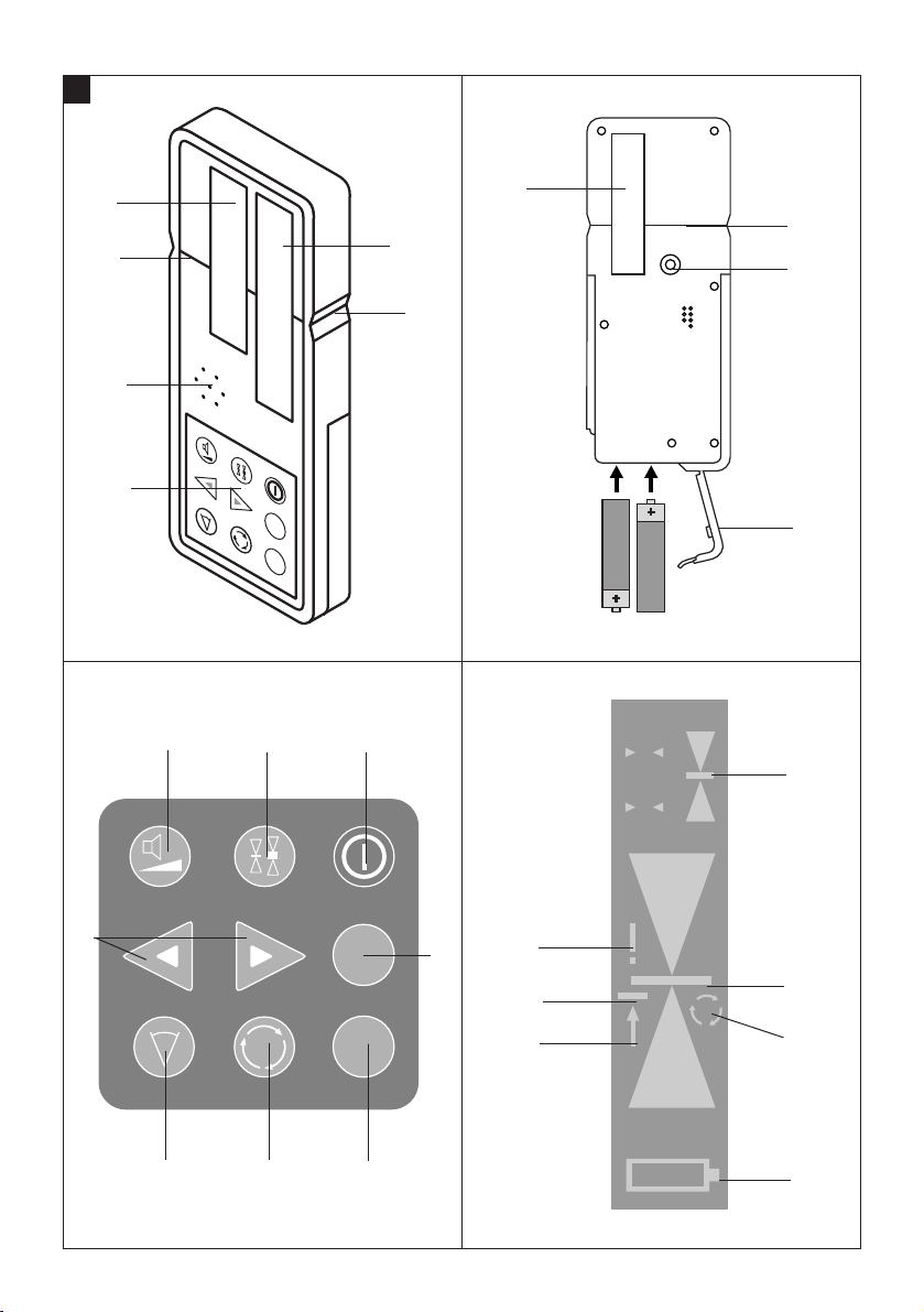
Component parts
PRA 25 laser detector
Control panel
Audible signal emission aperture
Detection area
Display, front side (detailed illustration)
Marking notch
Reference plane
Battery compartment cover
Mounting thread
Display, rear side
On/off key
Sensitivity selector key (standard or high
sensitivity)
Audible signal selector key
Direction adjustment key
Manual/auto alignment key
Line laser function key
Rotation speed selector key
Sensitivity indicator (standard or high)
These numbers refer to the corresponding illustrations. The illustrations can be found on the fold-out cover
pages. Keep these pages open when studying the operating instructions.
In these operating instructions, the PRA 25 laser detector is referred to as “ the tool”.
Location of identification data on the tool
The type designation and serial number can be found
on the type plate on the tool. Make a note of this data in
your operating instructions and always refer to it when
making an enquiry to your Hilti representative or service department.
Type: PRA 25
Serial no.:
Warning signs
Read the operating
instructions before use.
Symbols
General
warning
Indicator showing position of detector relative to
laser plane
Line laser function indicator
Beam catcher mode indicator
T
Rotation speed indicator
Z
Error indicator
U
Battery condition indicator
Page 6

2
en
2. Description
2.1 PRA 25 laser detector
The PRA 25 laser detector is designed to detect the laser
beam emitted by the PR 25 rotating laser and provide
remote control of its functions.
2.2 Features
The tool can be mounted on a measuring staff, telescopic
staff or, in conjunction with the appropriate holder, on
sight rails, wood lathes, frames etc.
3. Technical data
Operating range, detection
Operating range, remote control
Laser plane detection sensitivity (PR 25/10 m)
Audible signal
Liquid crystal display
Detection area
Center indicator, from top edge of housing
Marking notches (center)
Automatic cut-out
Dimensions
Weight
Power supply
Battery life at 20 °C (+68 °F)
Operating temperature
Storage temperature
Protection class
Mounting thread
Right of technical changes reserved.
2 to 200 m (6 to 650 ft); diameter
0 to 100 m (3 to 325 ft); diameter
High: ± 0.8 mm (0.03 inch);
Standard: ± 1.5 mm (0.06 inch)
2 volume levels or silent operation
On both sides
80 mm (3
1
/8inches)
50 mm (2 inches)
On both sides
After 30 min. when no laser beam is detected.
165
×67×
24 mm (6.5″×2.6″×0.9″inches)
0.2 kg (0.4 lbs) including batteries
2 x size AA batteries
Alkaline batteries: 30 hours
–20 °C to +50 °C (–4 °F to 122 °F)
–30 °C to +60 °C (–22 °F to 140 °F)
IP 56 (as per IEC 529)
M5 x 10 mm (0.4 inch)
Items supplied:
1 PRA 25 laser detector
1 PRA 25 operating instructions
1 PR 25/PRA 25 operating instructions
2 batteries (size AA)
Page 7

3
en
4. Safety precautions
4.1 Basic information concerning safety
In addition to the information relevant to safety given in
each of the sections of these operating instructions, the
following points must be strictly observed at all times.
● Tampering with or modification of the tool is not per-
missible.
● Observe the information printed in the operating instruc-
tions concerning operation, care and maintenance.
● Keep laser tools out of reach of children.
● Have the tool repaired only at a Hilti service centre.
● Take the surrounding conditions into account. Do not
use the tool where there is a risk of fire or explosion.
● Check the operating mode of the tool before each use.
4.2 Intended use
The tool is designed to be used in conjunction with the
PR 25 for determining, transferring or checking alignment in the horizontal plane, inclined planes and right
angles, e.g.
– Transferring datum and height marks
– Marking out right angles for walls
– Vertical alignment with a reference point
– Setting out inclines
Hilti offers various accessories that allow the tool to be
used with maximum efficiency (please refer to the
PR 25 operating instructions).
4.3 Proper organization of the workplace
● Avoid unfavorable body positions when working on
ladders. Work from a stable stance and stay in balance at all times.
● Measurements taken through panes of glass or other
objects may be inaccurate.
● Use the tool only within its specified limits.
4.4 Electromagnetic compatibility
Although the tool complies with the strict requirements
of the relevant directives, Hilti cannot entirely rule out
the following possibilities:
● The tool may cause interference to other equipment,
e.g. aircraft navigational equipment.
● The tool may be subject to interference caused by
powerful radiation, possibly leading to incorrect operation. Check the readings for plausibility when measuring under these conditions or if you are unsure of
the results.
4.5 General safety precautions
● Check the tool before use. If the tool is found to be
damaged, have it repaired at a Hilti service center.
● The accuracy of the tool must be checked after it has
been dropped or subjected to other mechanical stress.
● If mounting on an adaptor, ensure that the tool is
screwed on securely.
● To avoid measurement errors, keep the optical sen-
sor area on the detector and the laser exit aperture on
the rotating laser clean.
● Although the tool is designed for the tough conditions
of jobsite use, as with other optical instruments (binoculars, spectacles, cameras) it should be treated with
care.
● Although the tool is designed to prevent entry of damp-
ness, it should be wiped dry each time before being
put away in its transport container.
● Check that your PRA 25 responds only to your PR 25
and not to other PR 25 lasers that may be in use on
the construction site (see “Pairing”).
4.6 Electrical
● Do not allow the batteries to fall into children's hands.
● Do not overheat or incinerate the batteries. They may
explode or release toxic substances.
● Do not attempt to recharge the batteries (non-recharge-
able, alkaline type).
● Do not solder the batteries into the tool.
● Do not discharge the batteries by short circuiting. This
may cause the batteries to overheat and swell up.
● Do not attempt to open the batteries and do not sub-
ject them to excessive mechanical stress.
Page 8

4
en
6. Operation
6.1 Working with the tool
The laser beam and the functions of the tool are indicated by visual and audible signals.
-NOTE-
The tool can be used either as a remote control unit or
as a laser detector. When using the tool as a laser detector in conjunction with a measuring staff or telescopic
staff, check to ensure that it is attached securely.
6.1.1 Switching the tool on
Press the on/off key.
6.1.2 Setting the sensitivity
After switching on, the tool is set automatically to “Standard” beam detection sensitivity. Sensitivity can be set
to “High” by pressing the sensitivity selector key.
6.1.3 Adjusting the audible signal volume
After switching on, the tool is set automatically to “Normal” signal volume.
The volume can be set to “High” by pressing the signal
volume selector key and to “Off” by pressing the key a
second time.
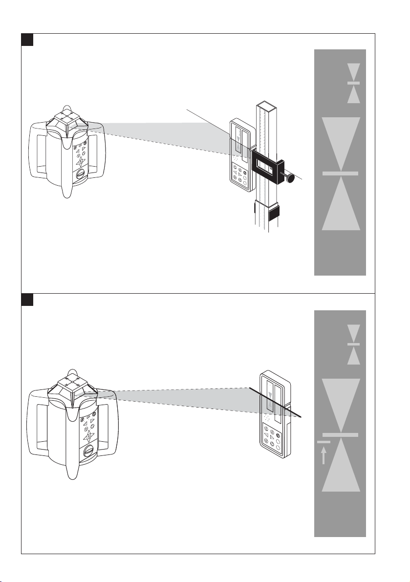
6.1.4 Detecting the laser beam
Hold the detector perpendicular to the plane of the rotating laser beam. Detection of the beam is indicated by an
audible signal and visually by illumination of the center
display segment.
6.1.5 Catching the laser beam
Hold the detector perpendicular to the plane of the rotating laser where the beam can be detected. Press the line
laser key once to switch to beam-catching mode. This
is indicated in the display by the line laser symbol and
an additional arrow. The beam is then “caught” and
remains stationary at the PRA 25 as soon as the PR 25
has located its position.
6.1.6 Adjusting the speed of rotation
The speed of rotation can be adjusted by pressing the
rotation speed selector key.
– Press the key once to set rotation to medium speed.
– Press the key again to set rotation to high speed.
– Press the key once more to return to medium speed.
– Press the key yet again to set rotation to low speed.
– A further press of the key stops rotation.
– The next press of the key sets rotation to low speed.
– This procedure repeats itself.
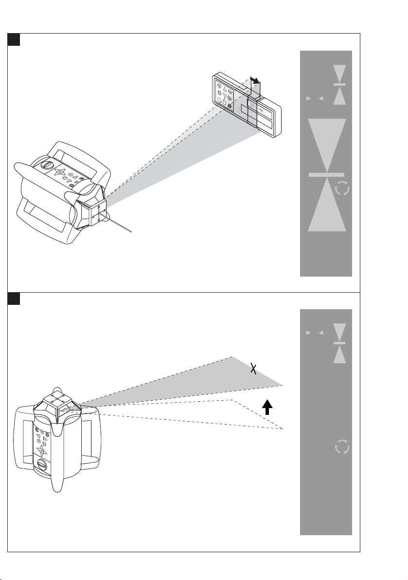
6.1.7 Line laser function
After pressing the line function key, the PR 25 projects
a laser line. The line can be lengthened or shortened by
pressing the key again.
– Press the key once to project a short line.
– Press the key again to project a medium-length line.
– Press the key once more to project a long line.
– Press the key yet again to project an extra-long line.
– A further press of the key switches the tool back to the
long line.
– The next press of the key switches the tool back to the
medium-length line.
– Press the key once more to switch to a short line.
– Press the key again to project a laser spot.
– This procedure repeats itself.
6.1.8 Moving the laser line and spot
The laser line or laser spot can be moved to the left or
right by pressing the direction keys.
Holding down the direction keys increases the speed of
movement and the laser line or spot then move continuously.
5. Before use
-NOTE-
– The tool may be powered only by the batteries rec-
ommended by Hilti.
-CAUTION-
– Do not use damaged batteries.
– Do not mix old and new batteries. Do not mix batter-
ies of different types or batteries from various manu-
facturers.
Page 9

5
en
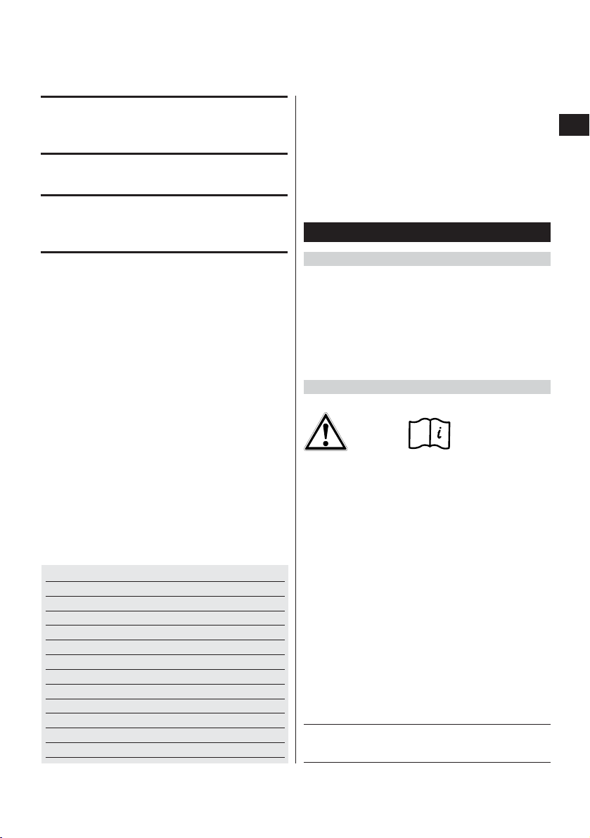
6.1.9 Automatic alignment
A basic prerequisite for auto alignment is that the PR 25
is set up exactly according to instructions. The PR 25
must be set up so that the correct axis (X or Y) is positioned in the direction in which alignment is to be performed. This can only be done in conjunction with the
PRA 25.
Procedure:
– Position the PR 25 at the reference point and with the
correct axis in the direction in which alignment is to
be performed (the operating range for auto alignment
is a radius of 5–50 m).
– Position the PRA 25 laser detector at the desired point.
– Check that no obstacles prevent communication between
the PR 25 and the PRA 25.
– Activate the auto alignment function by pressing the
X or Y key three times within one second. It is impor-
tant that the axes correspond correctly, i.e. when X (Y)
is to be aligned with the reference point, auto align-
ment of the X (Y) axis must be enabled by way of the
PRA 25.
– As long as the PR 25 is not in line laser mode, it then
switches automatically to medium rotation speed and
begins the search process. The auto align function is
indicated in the display by the axis currently being
aligned and by blinking arrows. An audible signal is
emitted continuously during the search process.
– The direction of the search process can be changed
by pressing the direction arrows.
– The beam moves to the zero point (reference plane)
as soon as the laser beam strikes the target area on
the PRA 25 detector.
– After reaching this point (finding the reference plane),
a signal sounds briefly indicating that the process is
complete. Only the axis that has been aligned is then
shown in the display.
If the process cannot be completed within a certain period
of time, an error is indicated in the display.
-NOTE- If an error is displayed
Please check that the PRA 25 is positioned within the
inclination range (+/–5°) and that no obstacles are located
between the rotating laser tool and the laser detector.
6.2. Manual alignment
A basic prerequisite for manual alignment is that the
PR 25 is set up accurately. The PR 25 must be set up so
that the correct axis (X or Y) is positioned in the direction in which alignment is to be performed.
Procedure:
– Position the PR 25 at the reference point and with the
correct axis in the direction in which alignment is to
be performed (the operating range for manual align-
ment is a radius of 5–50 m).
– Check that no obstacles prevent communication between
the PR 25 and the PRA 25.
– Activate the manual alignment function by pressing
the X or Y key twice within 1 second. It is important
that the axes correspond correctly, i.e. when X (Y) is
to be aligned with the reference point, auto alignment
of the X (Y) axis must be enabled by way of the
PRA 25.
– The laser beam can be moved to the desired position
by pressing the direction keys. Holding down the direction keys increases the speed of movement and the
laser line or spot then move continuously.
– The manual alignment function is indicated in the dis-
play by the axis currently being aligned and by stationary (constantly lit) arrows. An audible signal is also
emitted continuously during the search process.
– The system switches to normal operation when no key
is pressed within 5 seconds. Only the axis that has
been aligned is then indicated in the display.
6.2.1 Monitoring
The monitoring function checks to ensure that no displacement of the aligned plane has occurred (e.g. due
to vibration). If displacement has occurred, the laser
plane is realigned to the zero point (as long as it is still
within the detector target area). An additional laser detector is required for working with the monitoring function.
A PRA 20 or PRA 25 may be used to detect the laser
beam.
As monitoring begins by way of the auto alignment
function, the PR 25 must be set up accurately. The
PR 25 must be set up so that the correct axis (X or Y)
is positioned in the direction in which alignment is to be
performed.
Procedure:
– Position the PR 25 at the reference point and with the
correct axis in the direction in which alignment is to
be performed (the operating range for auto alignment
is a radius of 5–50 m).
– Position the PRA 25 laser detector at the desired point.
– Check that no obstacles prevent communication between
the PR 25 and the PRA 25.
– Activation of this function requires the PRA 25 to be
switched off. While pressing and holding the X or Y
key (the key for the axis you wish to align), switch on
the laser detector by pressing the on/off key.
– The system is then in monitoring mode. The moni-
toring function is indicated in the display – the LEDs
for the axis to be aligned and the arrows blink alter-
nately.
– The auto alignment process then begins as previously
described.
Page 10

6
– The auto alignment process stops as soon as the zero
point has been found. In contrast to full auto alignment, no audible signal is emitted at the end of the
process.
– A check is carried out at regular intervals to ensure
that laser plane has not been displaced. If it is found
to have been displaced, the laser plane is again brought
into alignment with the zero point (as long as the laser
beam is still within the detector target area and line of
sight between the rotating laser and the detector has
not been interrupted for a long period).
-NOTE- If an error is displayed
Please check that the PRA 25 is positioned within the
operating range (within a 5–50 m radius, inclination
range +/– 5°). Check that the line of sight between the
two devices is not obstructed during the entire monitoring period.
6.2.2 Pairing
It is possible to configure the PR 25 and the PRA 25 as
a pair. When the two devices are paired, the rotating laser
and the detector are assigned to each other. The rotating laser then receives commands only from its “own”
detector/remote control unit. The devices can be paired
by pressing and holding down the on/off keys on both
devices simultaneously.
-NOTE-
The PR 25 and PRA 25 are not paired when supplied.
Each unpaired rotating laser receives commands from
any unpaired detector/remote control.
Pairing procedure:
– The devices can be paired by pressing and holding
down the on/off keys on the PR 25 and PRA 25 simultaneously, as previously described, for more than
3 seconds. Successful pairing is confirmed by an audible signal emitted by the PRA 25 and by the LEDs on
the PR 25 blinking twice.
Canceling pairing:
– Pairing can be cancelled by pressing and holding down
the on/off keys for more than 3 seconds. Cancellation
of pairing can only be successful when the on/off keys
on the PR 25 and PRA 25 are not pressed simultaneously. Successful cancellation of pairing is confirmed
by the PRA 25 by the emission of an audible signal
and by the symbol “!” displayed. The PR 25 confirms
cancellation of pairing by causing all LEDs to blink.
en
Page 11

7
en
7. Hilti calibration service
We recommend that the tool is checked by the Hilti calibration service at regular intervals in order to verify its
reliability in accordance with standards and legal requirements. Use can be made of the Hilti calibration service
at any time, but checking at least once a year is recommended.
The calibration service provides confirmation that the
tool is in conformance, on the day it is tested, with the
specifications given in the operating instructions.
The tool will be re-adjusted if deviations from the manufacturer's specification are found. After checking and
adjustment, a calibration sticker applied to the tool and
a calibration certificate provide written verification that
the tool operates in accordance with the manufacturer's
specification.
Calibration certificates are always required by companies certified according to ISO 900x.
Your local Hilti Center or representative will be pleased
to provide further information.
7.1 Checking accuracy
Please refer to the PR 25 operating instructions.
8. Care and maintenance
8.1 Cleaning and drying
Use only a clean, soft cloth for cleaning. If necessary,
slightly moisten the cloth with pure alcohol or a little
water.
-NOTE-
● Do not use any other liquids as these may damage the
plastic parts.
● Observe the temperature limits when storing your
equipment. This is particularly important in winter or
summer, especially if the equipment is kept inside a
vehicle (storage temperatures: –30 °C to +60 °C/
–22 °F to +140 °F).
8.2 Storage
Remove the tool from its case if it has become wet. Clean
and dry the tool, its carrying case and accessories
(at max. temperature of 40 °C/108 °F). Re-pack the equipment only when it is completely dry.
Check the accuracy of the equipment before it is used
after a long period of storage or transportation.
8.3 Transportation
Use either the original Hilti cardboard box or packaging
of equivalent quality for transporting or shipping your
equipment.
-CAUTION-
Always remove the batteries before shipping the tool.
Page 12

8
en
9. Disposal
-CAUTION-
Improper disposal of the equipment may have serious consequences:
● The burning of plastic components generates toxic fumes which may present a health hazard.
● Batteries may explode if damaged or exposed to very high temperatures and thus cause poisoning, burns, acid
burns or environmental pollution.
● Careless disposal may permit unauthorized and improper use of the equipment, possibly leading to serious
personal injury, injury to third parties and pollution of the environment.
Most of the materials from which Hilti tools or appliances are manufactured can be recycled. The materials must
be properly separated before they can be recycled. In many countries, Hilti has already made arrangements for
taking back old tools and appliances for recycling. Ask Hilti Customer Service or your Hilti representative for further information.
Should you wish to return the tool or appliance yourself to a disposal facility for recycling, proceed as follows: Dismantle the equipment as far as is possible without need for special tools.
Separate the individual parts as follows:
Part/assembly
Housing
Control panel, display
Electronics
Batteries
Screws, small parts
* Dispose of batteries in accordance with national regulations.
Please help to protect our environment.
Main material
Plastic
Various
Various
Alkaline manganese
Steel
Recycling
Plastics recycling
Electronics scrap
Electronics scrap
*
Scrap metal
10. Warranty
Hilti warrants that the product supplied is free of defects
in material and workmanship. This warranty is valid as
long as the product is operated and handled correctly,
cleaned and serviced properly and in accordance with
the Hilti operating instructions, all warranty claims are
made within 12 months from the date of the sale (invoice
date), and the technical system is maintained. This means
that only genuine Hilti consumables, components and
spare parts may be used with the product.
This warranty provides the free-of-charge repair or replacement of defective parts only. Parts requiring repair or
replacement as a result of normal wear and tear are not
covered by this warranty.
Additional claims are excluded, unless stringent national
rules prohibit such exclusion. In particular, Hilti is not
obligated for direct, indirect, incidental or consequential
damages, losses or expenses in connection with, or
by reason of, the use of, or inability to use the product
for any purpose. Implied warranties of merchantability or fitness for a particular purpose are specifically
excluded.
Send the product and/or related parts immediately upon
discovery of the defect to the applicable Hilti marketing
organization for repair or replacement.
This constitutes Hilti's entire obligation with regard to
warranty and supersedes all prior or contemporaneous
comments and oral or written agreements concerning
warranties.
Page 13

9
en
This device complies with Part 15 of the FCC Rules and
RSS-210 of IC. Operation is subject to the following two
conditions:
(1) this device may not cause harmful interference, and
(2) this device must accept any interference received,
including interference that may cause undesired
operation.
Information plates on the product:
-CAUTION-
This equipment has been tested and found to comply
with the limits for a class B digital device, pursuant to
part 15 of the FCC rules.These limits are designed to
provide reasonable protection against harmful interference in a residential installation. This equipment generates, uses, and can radiate radio frequency energy and,
if not installed and used in accordance with the instructions, may cause harmful interference to radio communications.
However, there is no guarantee that interference will not
occur in a particular installation.
If this equipment does cause harmful interference to
radio or television reception, which can be determined
by turning the equipment on and off, the user is encouraged to try to correct the interference by one or more of
the following measures:
● Re-orient or re-locate the receiving antenna.
● Increase the distance between the equipment and
receiver.
● Consult the dealer or an experienced TV/radio tech-
nician for assistance.
(Requested by FCC §15.21): Changes or modifications
not expressly approved by Hilti could restrict the user's
right to operate the equipment.
11. FCC statement (applicable in US) / IC statement (applicable in Canada)
Page 14

10
en
12. EC conformity
In conformance with CE
We declare, on our own responsibility, that this product
complies with the following directives and standards:
EN 300 440-2, EN 301 489-3 V1.4.1,
EN 60950-1:2001/IEC 60950-1:2001
Designation: Laser detector
Type: PRA 25
Year of design: 2004
Hilti Corporation
Matthias Gillner Dr. Heinz-Joachim Schneider
Head BU Measuring Systems Executive Vice President
01 /2005 BA Electric Tools & Accessories
01 /2005
Page 15

Hilti Corporation
FL-9494 Schaan
Tel.: +423/ 2342111
Fax: +423 /23429 65
www.hilti.com
Hilti = registered trademark of Hilti Corp., Schaan W 3048 1004 10-Pos. 1 1 Printed in Liechtenstein © 2004
Right of technical and programme changes reserved S. E. & O.
000000 / A
 Loading...