

Page 1
PMP 34
*286153*
286153
Bedienungsanleitung de
Operating instructions en
Mode d’emploi fr
Istruzioni d’uso it
Gebruiksaanwijzing nl
Manual de instruções pt
Manual de instrucciones es
Οδηγιες χρησεως
el
zh
ja
ko
Page 2
Page 3
90∞
90∞
Page 4
Page 5
Page 6

1
en
It is essential that the operating instructions
are read before the tool is operated for the
first time.
Always keep these operating instructions
together with the tool.
Ensure that the operating instructions are
with the tool when it is given to other
persons.
PMP 34 point laser
1. General information
1.1 Safety notices and their meaning
-CAUTION-
Used to draw attention to a potentially dangerous situation which could lead to minor personal injury or
damage to the equipment or other property.
-NOTE-
Used to draw attention to an instruction or other useful information.
1.2 Pictograms
Contents Page
1. General information 1
2. Description 2
3. Accessories 2
4. Technical data 3
5. Safety precautions 3
6. Before use 5
7. Operation & applications 5
8. Checks 6
9. Care and maintenance 7
10. Troubleshooting 8
11. Disposal 8
12. Warranty 9
13. FCC statement 9
14. EC declaration of conformity 10
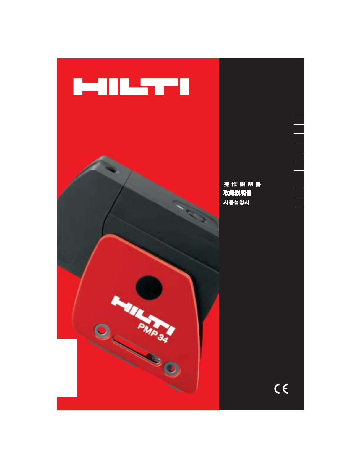
Component parts
Pendulum lockbutton
Selector button
LED indicator
Reference line
Pendulum
Base
Mounting slot
These numbers refer to the corresponding illustrations. The illustrations can be found on the fold-out
cover pages. Keep these pages open while studying
the operating instructions.
In these operating instructions, the PMP 34 point laser
is referred to as « the tool».
Location of identification data on the tool
The type designation and serial number can be found
on the type plate on the tool. Make a note of this information in your operating instructions and always refer
to it when making an enquiry to your Hilti representative or Hilti repair center.
Type: PMP 34
Serial no.:
Warning signs
Read the
operating
instructions
before use.
Symbols
General warning
Laser warning:
Laser radiation
Do not look into the beam
Laser class 2
CLASS II LASER PRODUCT
620-690nm/0.95mW max.
LASER RADIATION - DO NOT
STARE INTO BEAM
1/4
s
2
Disposal of electric
tools and batteries
together with
household waste is
not permissible.
BA_PMP34_en.qxd 22.11.2004 12:49 Uhr Seite 1
Page 7

2
en
2. Description
The PMP 34 is a self-leveling point laser which can be
used by one person working alone to plumb, level,
align and transfer right angles very quickly and with
great accuracy. The tool incorporates 4 coincident
laser beams (beams that originate from the same point).
All the beams have the same range (30 m*).
*The range depends on the ambient light conditions.
Features:
● High horizontal and plumb beam accuracy (± 3 mm
at 10 m).
● Self leveling in all planes within ± 5°.
● Short self-leveling time: ~ 3 seconds.
● “Out of level” warning signal when the self-leveling
range is exceeded (the laser beams blink).
● Rugged, impact-resistant plastic casing.
● Compact and light – easy to use and carry with you.
● Automatic cut-out: The tool switches itself off auto-
matically after 15 minutes. Continuous operating
mode may be selected if desired.
● Easy to operate.
2.1 Items supplied with the point laser
(cardboard box version)
1 PMP 34 point laser
1 soft pouch
4 batteries
1 operating instructions
1 PMA 73 drywall adaptor
2 target plates
1 manufacturer’s certificate
2.2 Items supplied with the point laser
(Hilti toolbox version)
1 PMP 34 point laser
1 soft pouch
4 batteries
1 operating instructions
1 PMA 73 drywall mount
1 PMA 71 wall bracket
1 PA 250 frame clamp
1 PMA 74 magnetic bracket
2 target plates
1 manufacturer’s certificate
3. Accessories
Accessories:
Various tripods
Target plate (CM)
Target plate (IN)
Soft pouch
Pipe adaptor
Wall mount
Drywall adaptor
Magnetic bracket
Telescopic brace
Frame clamp
Hilti toolbox
Laser visibility glasses*
* These are not protective glasses and thus do not protect the eyes from laser radiation. As the laser visibility
glasses restrict color vision, they should be worn only when working with the PML/PMP and must not be worn
while driving a vehicle on a public road.
PA 910, PA 911, PA 921 and PA 931/2
PMA 50
PMA 51
PMA 60
PMA 70
PMA 71
PMA 73
PMA 74
PUA 10
PA 250
PMP 34
PUA 60
BA_PMP34_en.qxd 22.11.2004 12:49 Uhr Seite 2
Page 8

3
en
4. Technical data
Range
Accuracy at 25 °C
● Front beam (horizontal):
● Perpendicular beam (horizontal):
● Angle (horizontal):
● Plumb beams:
Self-leveling time
Laser class
Beam diameter
Self-leveling range
Automatic switch-off
Operating status indicators
Power supply
Battery life at 25 °C [+77 °F]
Operating temperature range
Storage temperature
Protection against dust and water spray
Tripod thread
Weight
Dimensions: closed
opened
*Range depends on the ambient light conditions.
Rigth of technical changes reserved.
30 m*
± 3 mm at 10 m (
1
/8 in at 30 ft)
± 3 mm at 10 m (
1
/8 in at 30 ft)
90° ± 60″
± 3 mm at 10 m (
1
/8 in at 30 ft)
~ 3 seconds
Class 2, visible, 635 ± 10 nm @ 25 °C
(IEC825-1; EN 60825-01:2003; CFR 21 § 1040 (FDA))
≤ 3 mm @ 5 m @ 25 °C/≤ 12 mm @ 20 m @ 25 °C
±5°
Activated after 15 min.
LED + laser beams
4 x alkaline batteries, size AA
Alkaline batteries: > 40 h with 2 beams (horizontal or
vertical) in use
–10 °C up to +40 °C (± 2) °C/+14 °F up to 104 (± 4) °F
–20 °C up to +63 °C/–4 °F up to 145 °F
IP 54 (in accordance with IEC 529) except battery
compartment
BSW
5
/8″ and UNC 1/4″
660 g without batteries
ca.138 (L) x 51 (W) x 89 (H) mm
ca.164 (L) x 51 (W) x 126 (H) mm
5.3 Misuse of the tool
● Do not use the tool unless its accuracy has been pre-
viously checked.
● The tool and its ancillary equipment may present
hazards when used incorrectly by untrained personnel or when used not as directed.
● Do not open the casing of the tool.
● To avoid the risk of injury, use only original Hilti acces-
sories and additional equipment.
● Modification of the tool is not permissible.
● Observe the information printed in the operating
instructions concerning operation, care and maintenance.
● Do not render safety devices ineffective and do not
remove information and warning notices.
● Keep laser tools out of reach of children.
5. Safety precautions
5.1 Basic information concerning safety
In addition to the information relevant to safety given
in each of the sections of these operating instructions,
the following points must be strictly observed at all
times.
5.2 Correct use of the tool
The tool is designed for predominantly indoor use for
determining and checking differences in the height of
points in the horizontal plane, vertical lines, alignment
and for marking plumb points. When used for outdoor
applications, care must be taken to ensure that the conditions under which the tool is used correspond to the
conditions encountered indoors.
Examples of applications:
● Transferring datum marks and height marks.
● Marking out the position of partitions (at right angles
and in the vertical plane).
● Aligning equipment/installations and other structural
elements in three axes.
● Checking and transferring right angles.
● Transferring points marked on the floor to the ceiling.
BA_PMP34_en.qxd 22.11.2004 12:49 Uhr Seite 3
Page 9

4
en
● Have the tool repaired only at a Hilti service center.
Failure to follow the correct procedures when opening the tool may cause emission of laser radiation in
excess of class 2.
● Do not expose the tool to rain or snow and do not
use it in damp or wet environments or where there
may be a risk of explosion.
5.4 Proper organization of the workplace
● Secure the area in which you are working and take
care to avoid directing the beam toward other persons or toward yourself while setting up the tool.
● Avoid unfavorable body positions when working on
ladders or scaffolding. Make sure you work from a
safe stance and stay in balance at all times.
● Measurements taken through panes of glass or other
objects may be inaccurate.
● Ensure that the tool is set up on a solid, level surface.
● Ensure that the tool is set up on a steady surface not
exposed to vibration.
● Use the tool only within the specified limits of the
application for which it is intended (see Section 5.2).
5.4.1 Electromagnetic compatibility
Although the tool complies with the strict requirements
of the relevant directives, Hilti cannot entirely rule out
the following possibilities:
● The tool may cause interference to other equipment
(e.g. aircraft navigation equipment, medical instruments or devices).
● The tool may be subject to interference caused by
powerful radiation, which may lead to incorrect operation. Check the accuracy of the tool by taking measurements by other means when working under such
conditions or if you are unsure.
5.4.2 Laser classification
The tool conforms to laser class 2 based on the
IEC825-1/EN60825-01 2003 standard and class II based
on CFR 21 § 1040 (FDA). The eyelid closure reflex
protects the eyes when a person looks into the beam
unintentionally for a brief moment. Nevertheless,
the eyelid closure reflex may be negatively affected
by medicines, alcohol or drugs. This tool may be used
without need for further protective measures. Nevertheless, as with the sun, one should not look directly
into sources of bright light. Do not direct the laser beam
toward persons.
Laser warning plate based on IEC825/EN 6082501:2003:
Laser warning plate for the USA based on CFR 21 §
1040 (FDA):
This laser product complies with CFR 21 § 1040 (FDA)
as applicable.
5.5 General safety precautions
● Check the tool for possible damage or dirt before
use. If the tool is found to be damaged, have it repaired
at a Hilti service center.
● The accuracy of the tool must be checked after it has
been dropped or subjected to other mechanical
stresses.
● When the tool is brought into a warm environment
from very cold conditions, or vice-versa, allow it to
become acclimatized before use.
● If mounting on an adaptor, ensure that the tool is
attached securely.
● Keep the laser exit aperture clean to avoid measure-
ment errors.
● Although the tool is designed for the tough conditions
of jobsite use, as with other optical instruments (binoculars, spectacles, cameras) it should be treated with
care.
● Although the tool is protected to prevent entry of
dampness, it should be wiped dry each time before
being put away in its Hilti toolbox.
5.5.1 Electrical hazards
● The batteries must be insulated or removed from the
tool before it is shipped.
● The tool and the batteries must be disposed of in
accordance with national regulations in order to avoid
environmental pollution. Consult the manufacturer if
you are unsure.
CLASS II LASER PRODUCT
620-690nm/0.95mW max.
LASER RADIATION - DO NOT
STARE INTO BEAM
1/4
s
2
BA_PMP34_en.qxd 22.11.2004 12:49 Uhr Seite 4
Page 10

5
en
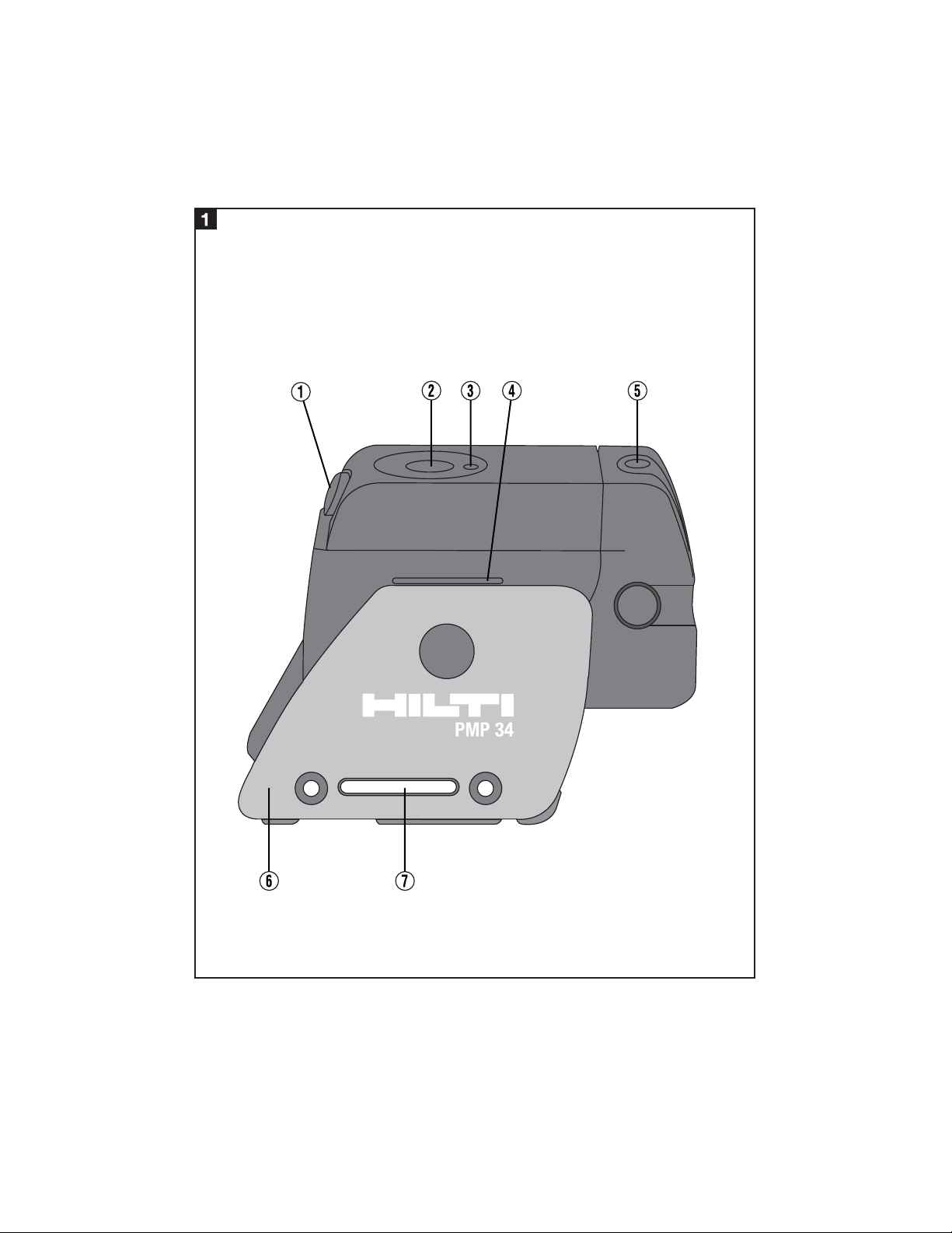
6. Before use
6.1 Inserting new batteries
-NOTE-
Do not use damaged batteries.
Do not mix old and new batteries. Do not mix batteries
of different makes or types.
1. Bring the two parts of the tool into the closed position.
2. Press the battery compartment release button.
3. Pull the battery holder downwards out of the tool.
4. Replace the batteries.
-CAUTION- Take care to observe correct polarity.
5. Close the battery compartment. Check that it engages
securely.
7. Operation & applications
-NOTE-
The pendulum is locked when the tool is in the closed
position (laser beam blinks).
7.1 Operation
7.1.1 Bringing the tool into the operating position
1. Open the tool to the 90° or 180° position.
2. Bring the reference line into alignment with (parallel to) the top edge of the base section.
-NOTE-
The pendulum is able to swing freely when the reference line is parallel to the base section, when the pendulum lockbutton is not pressed in and when the tool
is set up in a horizontal position (≤ ±5°).
The laser beams blink rapidly when the tool is unable
to level itself automatically.
7.1.2 Switching on the laser beams
Switching on only the plumb beams (vertically upwards
and downwards):
1. Press the selector button once.
Switching on only the front and perpendicular beams:
1. Press the selector button twice.
Switching on the plumb beams, front beam and perpendicular beam:
1. Press the selector button three times.
7.1.3 Switching the tool/laser beams off
1. Press the selector button repeatedly (1-3 times depending on previous operating mode) until the laser beam
is no longer visible and the LED no longer lights.
-NOTE-
The tool switches itself off automatically after approx.
15 minutes.
7.1.4 Deactivating the automatic cut-out
1. Press and hold the selector button (approx. 4 seconds) until the laser beam blinks three times in confirmation.
-NOTE-
The tool will be switched off when the selector button
is pressed (between one and three times, depending
on operating mode) or when the batteries are exhausted.
7.2 Examples of applications
7.2.1 Vertical alignment (plumbing) of sections
of a steel structure
7.2.2 Vertical alignment of door and window
frames
7.2.3 Setting out drywall track for a partition
wall
7.2.4 Aligning pipe fastenings
BA_PMP34_en.qxd 22.11.2004 12:49 Uhr Seite 5
Page 11

6
7.3 Operating status indicators
7.3.1 LED
7.3.2 Laser beam
The LED doesn’t light.
The LED lights constantly.
The LED blinks.
● The tool is switched off.
● The batteries are exhausted.
● The batteries are inserted incorrectly.
● The laser beam is switched on. The tool is in opera-
tion.
● The batteries are almost exhausted.
● The temperature of the tool is above 40 °C (104 °F)
or below –10 °C (14 °F) (no laser beam projected).
The laser beam blinks twice every 10 seconds.
The laser beam blinks rapidly.
● The batteries are almost exhausted.
● The tool is in the closed position.
● The pendulum is locked.
● The tool cannot level itself automatically.
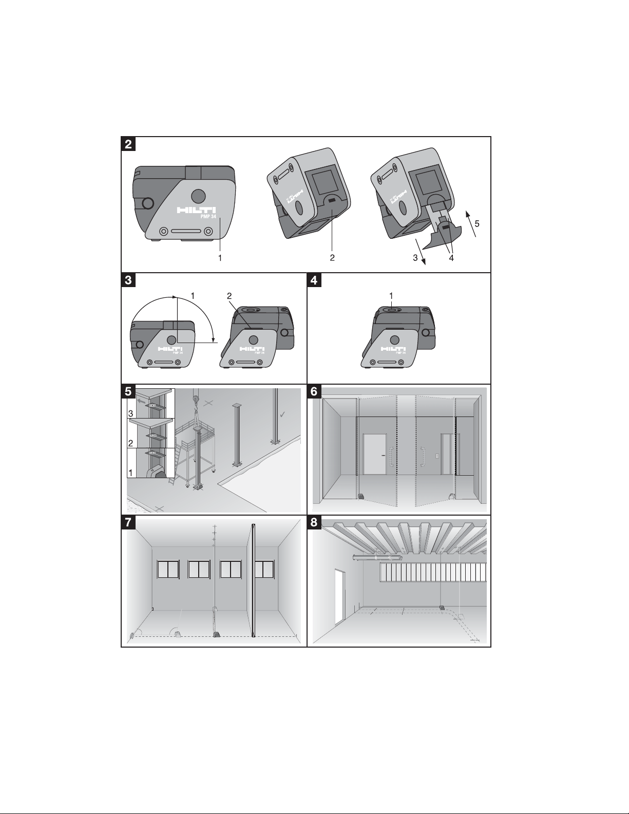
8. Checks
8.1 Checking the vertical (plumb) beam
1. Make a mark on the floor (a cross) in a high room (e.g.
in a stairwell or hallway with a height of 5–10 m).
2. Place the tool on a level surface (floor).
3. Switch on the vertical beam.
4. Position the tool with the lower beam on the center
of the cross.
5. Mark the position of the vertical beam on the ceiling (attach a piece of paper to the ceiling).
6. Pivot the tool through 90°. The reference beam must
remain on the center of the cross.
7. Mark the position of the vertical beam on the ceiling.
8. Repeat the procedure after pivoting the tool through
180° and 270°.
-NOTE-
The resulting 4 marks define a circle in which the intersection of the diagonals d1 (1 – 3) and d2 (2 – 4)
marks the exact center of the plumb point.
Calculation of accuracy
Result= @ (1) or
Result= @ (2)
The result provided by this formula refers to the tool's
accuracy in mm at 10 m (formula (1)). This result should
be within the specification for the tool (3 mm at 10 m).
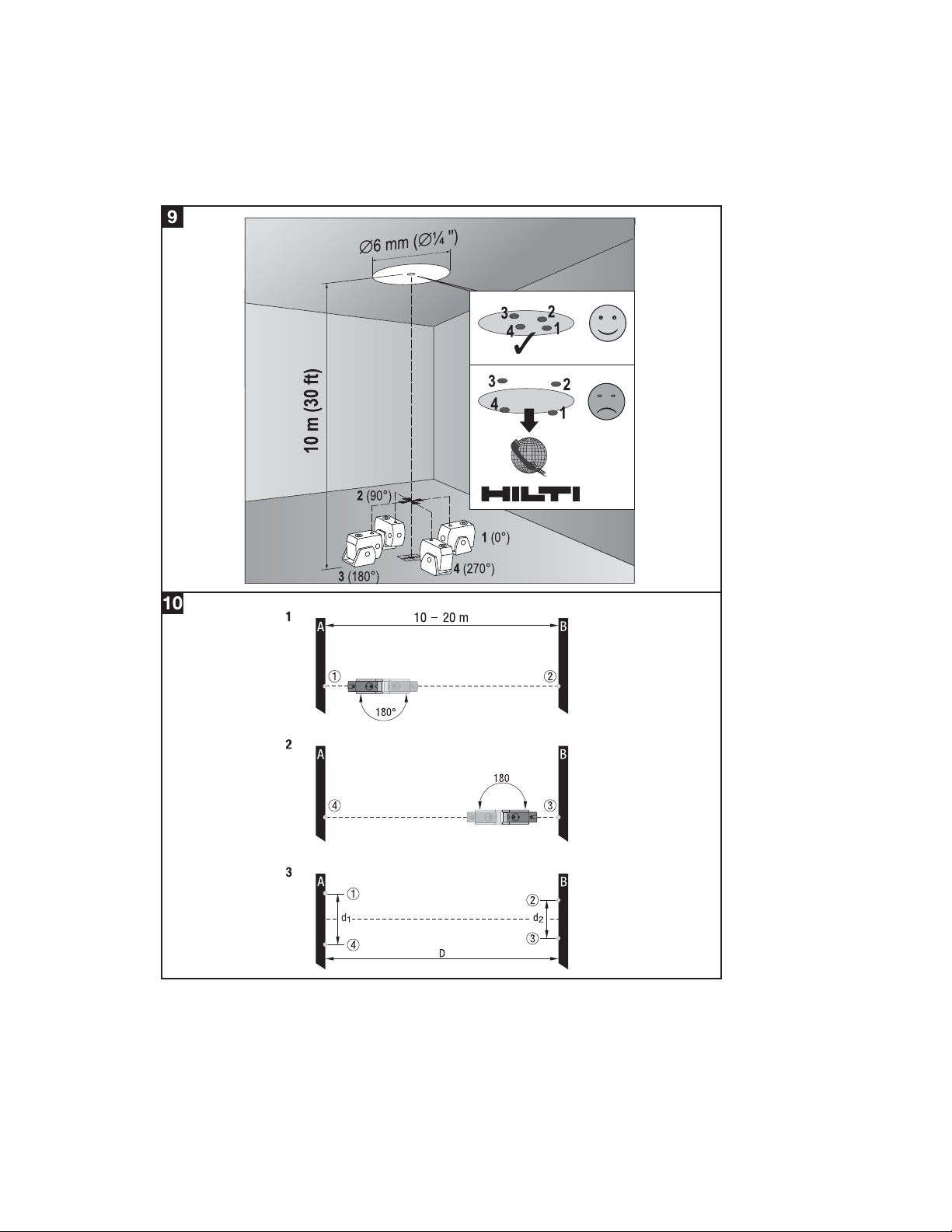
8.2 Checking the front beam and/or perpendicular
beam for height deviation
1. Place the tool on a smooth, horizontal surface approx.
20 cm from the wall (A) with the laser beam directed
toward the wall (A).
2. Mark the position of the center (1) of the laser beam
on the wall (A) with a cross.
3. Pivot the tool through 180° and mark the center of
the laser beam (2) on the opposite wall (B) with a
cross.
4. Place the tool on a smooth, horizontal surface approx.
20 cm from the wall (B) with the laser beam directed
toward the wall (B).
5. Mark the position of the center (3) of the laser beam
on the wall (B) with a cross.
6. Pivot the tool through 180° and mark the center of
the laser beam (4) on the opposite wall (A) with a
cross.
Calculation of accuracy
1. Measure the distances d1 between 1 and 4 and d2
between 2 and 3.
2. Mark the mid points of d1 and d2.
– If the reference points 1 and 3 are located on dif-
ferent sides of the mid point (see example), then
subtract d2 from d1.
– If the reference points 1 and 3 are located on the
same side of the mid point, then add d1 and d2
together.
3. Divide the result by twice the length of the room
(room length x 2).
10
Room height [m]
(d1 + d2) [mm]
4
30
Room height [ft]
(d1 + d2) [inch]
4
en
BA_PMP34_en.qxd 22.11.2004 12:49 Uhr Seite 6
Page 12

7
en
The maximum permissible error is 3 mm at 10 m.
Example:
d1 = 6 mm/d2 = 4 mm/room length (D) = 10 m.
Points 1 and 3 are on different sides of the exact horizontal.
= = 1 mm/10 m
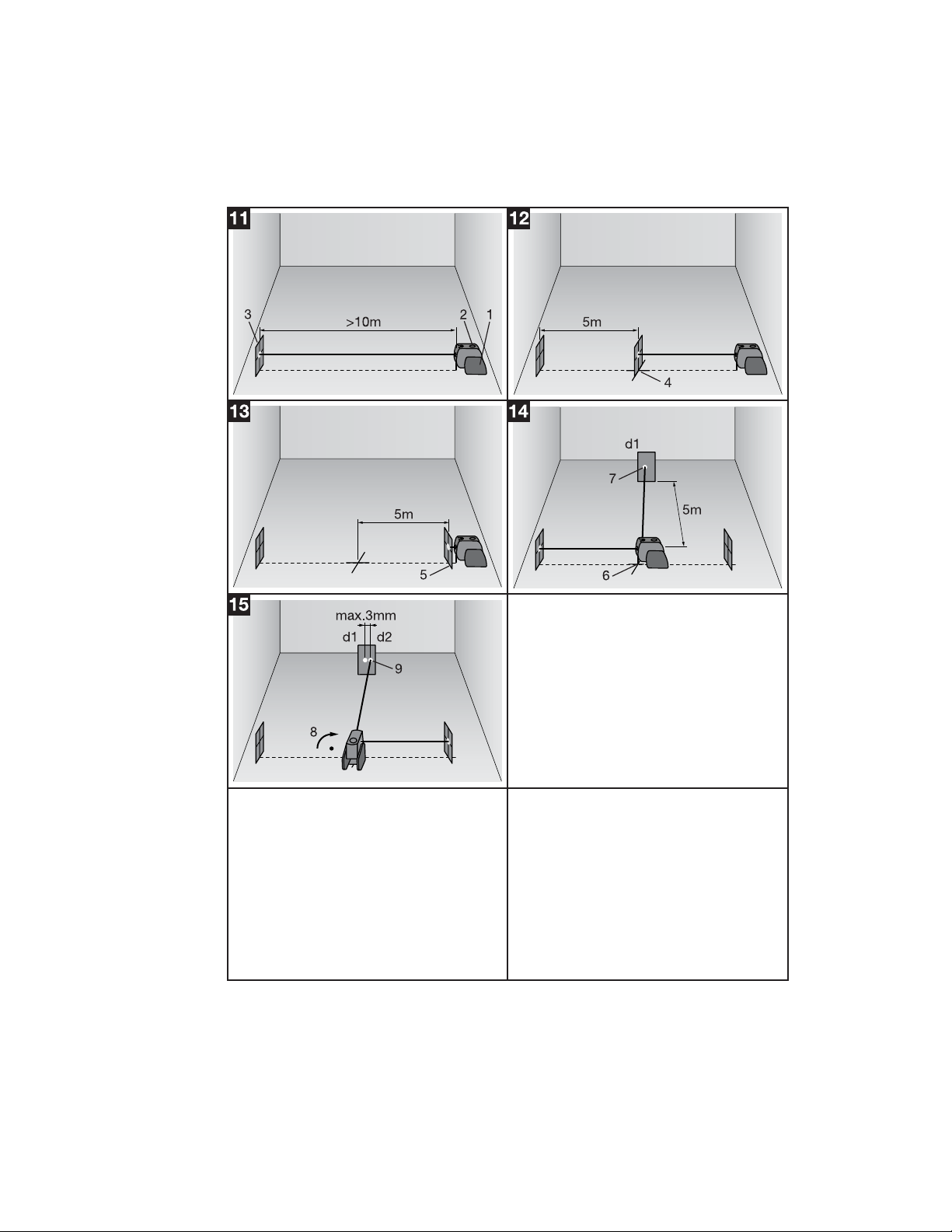
8.3 Checking the angle between the front beam
and the perpendicular beam
1. Place the tool on a smooth, horizontal surface at the
edge of a room with a length of at least 10 m and
width of at least 5 m.
2. Switch on all four beams.
3. Fix a target plate (#1) at a distance of at least 10 m
from the tool so that the front beam strikes exactly
the center of the target plate.
4. Using a second target plate, mark a reference cross
on the floor at a distance of 5 m (measure the distance) from the first target plate. The beam must
strike the second target plate exactly in the center
(cross-hairs).
5. Fix a target plate (#2) at a distance of 5 m from the
reference cross so that the front beam strikes exactly
the center of the target plate.
6. Now position the tool with the lower plumb beam
exactly on the center of the reference cross so that
the front beam strikes exactly the center of target
plate 1. The tool is exactly 5 meters from the two
fixed target plates.
7. Mark the position (d1) of the perpendicular beam
with a target plate at a distance of 5 m (fix the target plate in position).
8. Pivot the tool to the right through 90°. The lower
plumb beam must remain in the center of the reference cross. The perpendicular beam must strike
target plate 2 exactly in the center (cross-hairs).
9. Mark the position (d2) of the front beam on the target
plate which is still fixed at a distance of 5 meters.
-NOTE-
The horizontal distance between d1 and d2 must be
no greater than 3 mm at a working distance of 5 m.
8.3.1 Calculation of accuracy (g) at a working
distance other than 5 m
g = (3 mm x working distance (m))/5 m.
In this case, the horizontal distance between d1 and
d2 must not exceed the value (g) at the defined working distance (m).
6 mm–4 mm
10 x 2
2 mm
20 m
9. Care and maintenance
9.1 Cleaning and drying
● Blow dust off the glass.
● Do not touch the glass with your fingers.
● Use only a clean, soft cloth for cleaning. If neces-
sary, moisten the cloth slightly with pure alcohol or
a little water.
-NOTE-
● Do not use any other liquids as these may damage
the plastic components.
● Observe the temperature limits when storing your
equipment. This is particularly important in summer
if the equipment is kept inside a motor vehicle
(–20 °C to + 63 °C/–4 °F to 145 °F).
9.2 Storage
Remove the tool from its case if it has become wet.
The tool, its carrying case and accessories should be
cleaned and dried (at maximum 40 °C/104 °F). Repack
the equipment only once it is completely dry.
Check the accuracy of the equipment before it is used
after a long period of storage or transportation. Remove
the batteries if the tool is not used over a long period.
Leaking batteries may damage the tool.
9.3 Transportation
Use the Hilti shipping carton, Hilti toolbox or packaging of equivalent quality for transporting or shipping
your equipment.
-NOTE-
Always remove the batteries before shipping.
BA_PMP34_en.qxd 22.11.2004 12:49 Uhr Seite 7
Page 13

8
en
10. Troubleshooting
Fault
The tool can’t be switched
on.
Individual laser beams
don’t function.
The tool can be switched on
but no laser beam is visible.
Automatic leveling doesn’t
function.
The base section cannot be
brought into the operating
position.
Possible causes
Batteries are exhausted.
Batteries are inserted the wrong way
round (incorrect polarity).
Battery compartment is not closed.
Tool or selector button is defective.
The laser source or
laser control is defective.
The laser source or laser control is
defective.
Temperature too high or too low.
The surface on which the tool is set up
is excessively inclined.
The pendulum is locked.
Extraneous light is too bright.
The tilt sensor is defective.
The base section (hinge) is dirty.
The base section is bent.
Remedy
Replace the batteries.
Insert the batteries correctly.
Close the battery compartment.
Bring the tool to a Hilti repair center.
Bring the tool to a Hilti repair center.
Bring the tool to a Hilti repair center.
Allow the tool to cool down or,
respectively, warm up.
Set up the tool in a level position.
Release the pendulum.
Reduce extraneous light.
Bring the tool to a Hilti repair center.
Clean the base section.
Bring the tool to a Hilti repair center.
11. Disposal
-CAUTION-
Improper disposal of the equipment may have serious consequences:
● The burning of plastic components generates toxic fumes which may present a health hazard.
● Batteries may explode if damaged or exposed to very high temperatures, causing poisoning, burns, acid burns
or environmental pollution.
● Careless disposal may permit unauthorized and improper use of the equipment. This may result in serious per-
sonal injury, injury to third parties and pollution of the environment.
Most of the materials from which Hilti tools or appliances are manufactured can be recycled. The materials must
be correctly separated before they can be recycled. In many countries, Hilti has already made arrangements for
taking back old tools and appliances for recycling. Ask Hilti customer service or your Hilti representative for further information.
Should you wish to return the tool or appliance yourself to a disposal facility for recycling, dismantle the tool as
far as is possible without the need for special tools.
Separate the individual parts as follows:
Part/assembly
Casing, Hilti toolbox
Switch
Screws, small parts
Electronics
Batteries
Soft pouch
* Disposal of batteries together with household waste is not permissible.
For EC countries only:
Disposal of electric tools together with household waste is not permissible!
In observance of European Directive 2002/96/EC on waste electrical and electronic equipment
and its implementation in accordance with national law, electric tools that have reached the end
of their life must be collected separately and returned to an environmentally compatible recycling facility.
Main material
Plastic, steel
Plastic
Steel, aluminium, magnets, copper
Various
Alkaline manganese
Woven synthetic material
Recycling
Plastics recycling, scrap metal
Plastics recycling
Scrap metal
Electronics scrap
*
Plastics recycling
BA_PMP34_en.qxd 22.11.2004 12:49 Uhr Seite 8
Page 14

9
en
12. Warranty
Hilti warrants that the tool supplied is free of defects in
material and workmanship. This warranty is valid as long
as the tool is operated and handled correctly, cleaned
and serviced properly and in accordance with the Hilti
operating instructions, all warranty claims are made
within 12 months (unless other mandatory national regulations prescribe a longer minimum period) from the
date of sale (invoice date) and the technical system is
maintained, i.e. only genuine Hilti consumables, accessories and spare parts are used with the product.
This warranty provides the free-of-charge repair or
replacement of defective parts only. Parts requiring
repair or replacement as a result of normal wear and
tear are not covered by this warranty.
Additional claims are excluded, unless stringent national
rules prohibit such exclusion. In particular, Hilti is not
obligated for direct, indirect, incidental or consequential
damages, losses or expenses in connection with, or
by reason of, the use of, or inability to use the tool for
any purpose. Implied warranties of merchantability or
fitness for a particular purpose are specifically excluded.
Send the tool and/or related parts immediately upon discovery of a defect to the local Hilti marketing organization for repair or replacement.
This constitutes Hilti’s entire obligation with regard to
warranty and supersedes all prior or contemporaneous
comments and oral or written agreements concerning
warranties.
– Connect the equipment to an outlet on a circuit dif-
ferent from that to which the receiver is connected.
– Consult your dealer or an experienced TV/radio tech-
nician for assistance.
Changes or modifications not expressly approved by
Hilti could limit the user’s right to operate the equipment.
Labels
-CAUTION-
This equipment has been tested and found to comply
with the limits for a Class B digital device, pursuant to
part 15 of the FCC rules. These limits are designed to
provide reasonable protection against harmful interference in a residential installation. This equipment generates, uses and may radiate radio frequency energy.
Accordingly, if not installed and used in accordance
with the instructions, it may cause harmful interference to radio communications.
However, there is no guarantee that interference will
not occur in a particular installation.
If this equipment does cause harmful interference to
radio or television reception, which can be determined
by turning the equipment off and on, the user is encouraged to try to correct the interference by taking the following measures:
– Reorient or relocate the receiving antenna.
– Increase the separation between the equipment and
receiver.
13. FCC statement (applicable in USA)
319695
PMP 34
Hilti =trademark of Hilti Corp., Schaan, LI Made in Germany
Item.no.
S.No.
Manufact:
6V=
100mA max.
BA_PMP34_en.qxd 22.11.2004 12:49 Uhr Seite 9
Page 15

10
en
14. EC declaration of conformity
In conformance with CE requirements
We declare, on our sole responsibility, that this product
complies with the following directives and standards:
EN 61000-6-3 and EN 61000-6-2 in accordance with
directive 89/336/EEC.
Description: Point laser
Type designation: PMP 34
Serial number: 000 00 001–500 00 000
Year of design: 2004
Hilti Corporation
Matthias Gillner Dr. Heinz-Joachim Schneider
Head of Business Unit Executive Vice President
Measuring Systems Business Area Electric Tools &
11 /2004 Accessories
11 /2004
BA_PMP34_en.qxd 22.11.2004 12:49 Uhr Seite 10
Page 16

*286153*
Hilti Corporation
FL-9494 Schaan
Tel.:+423 /234 2111
Fax: +423 / 234 2965
www.hilti.com
Hilti = registered trademark of Hilti Corp., Schaan W 3060 0605 00-Pos. 1 1 Printed in Liechtenstein © 2005
Right of technical and programme changes reserved S. E. & O.
286153 / C
 Loading...