

Page 1

PML 32
Operating instructions 1-36
*377396*
377396
en
Page 2
Page 3
Page 4
Page 5

1
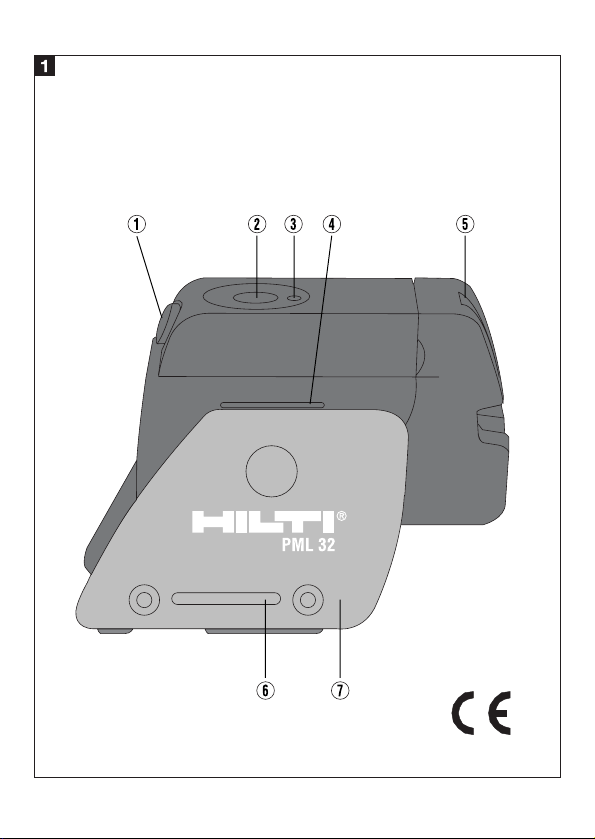
Component parts
1. Pendulum lockbutton
2. Selector button
3. LED indicator
4. Reference line
5. Pendulum
6. Mounting slot
7. Base section
It is essential that the operating instructions are read
before the tool is operated for the first time.
Always keep these operating instructions together with
the tool.
Ensure that the operating instructions are with the tool
when it is given to other persons.
Page 6

1. General information
1.1 Signal words and their meaning
-CAUTION-
Used to draw attention to a potentially dangerous
situation which could lead to minor personal injury
or damage to the equipment or other property.
-NOTE-
Used to draw attention to an instruction or other
useful information.
2
Contents / 1. General information
Contents
1. General information .........................................................................2
2. Description.......................................................................................4
3. Accessories......................................................................................6
4. Technical data ..................................................................................7
5. Safety precautions ...........................................................................9
6. Before use......................................................................................16
7. Operation .......................................................................................15
8. Checks ...........................................................................................20
9. Care and maintenance....................................................................26
10. Troubleshooting...........................................................................28
11. Disposal.......................................................................................29
12. Warranty......................................................................................31
13. FCC statement..............................................................................33
14. EC declaration of conformity........................................................35
Page 7

3
1. General information
1.2 Pictograms
Symbols
Laser radiation. Do not look into the beam
Laser class 2
General warning
Read the operating instructions before use.
These numbers refer to the corresponding illustrations. The
illustrations can be found on the fold-out cover pages. Keep these
pages open while studying the operating instructions. In these
operating instructions, the PML 32 line laser is referred to as «the
tool».
Location of identification data on the tool
The type designation and serial number can be found on the type plate
on the tool. Make a note of this information in your operating
instructions and always refer to it when making an enquiry to your
Hilti representative or service department.
Type : PML 32
Serial no.: ___________
Warning signs
Page 8

The tool projects two laser lines at 90° to each other
(when projected onto a vertical, even surface situated at
90° to the tool). Leveling is automatic within ±5°.
The automatic leveling system can be deactivated for
applications in an inclined plane.
Operating modes:
- Horizontal laser beam
- Vertical laser beam
- Horizontal and vertical laser beams
- Inclined plane (pendulum deactivated)
2.1 Items supplied with the line laser (cardboard box version)
PML 32 line laser
Soft case
4 batteries
Operating instructions
Laser sighting glasses *
2 target plates
4
2. Description
2. Description
Page 9

5
2. Description
2.2 Items supplied with the line laser (Hilti toolbox version)
PML 32 line laser
Soft case
4 batteries
Operating instructions
Laser sighting glasses *
Wall bracket
Pipe adaptor
Frame clamp
2 target plates
* These are not protective glasses and thus do not
protect the eyes from laser radiation. As they restrict
color vision, they must not be worn while driving a
vehicle on a public road.
Page 10

3. Accessories
6
Accessories
Various tripods PA 910, PA 911, PA 921, PA 930 and
PA 931/2
Wall bracket PMA 71
Pipe adaptor PMA 70
Telescopic pole PVA 10
Frame clamp PA 250
Hilti toolbox
Sighting glasses* PA 970
* These are not protective glasses and thus do not
protect the eyes from laser radiation. As they restrict
color vision, they must not be worn while driving a
vehicle on a public road.
3. Accessories
Page 11

7
4. Technical data
4. Technical data
Operating conditions
Projection onto an even, vertical surface
Tool aligned at 90° to the surface
Self-leveling within the ± 5° range
Range
10m
Line accuracy from end to end
≤ ±1.5mm for a line with a lenght of 10 m @ 25°C
Laser class
Class 2, visible, 635 ± 10 nm @ 25°C
(IEC825-1; EN60825-01 ; CFR 21 § 1040 (FDA))
Line width
≤ 2mm @ 5m @ 25°C
Beam width (projection angle)
120° with pendulum in middle position
Self-leveling range
±5°
Automatic switch-off
Activated after 15 min.
Page 12

8
4. Technical data
Operating status indicators
LED + laser beams
Power supply
4 x alkaline batteries, size AA
Battery life at 25°C [+77°F]
Alkaline: > 40 h (1 line)
Operating temperature range
-10°C up to +40°C (±2) °C / +14°F up to 104 (±4)°F
Storage temperature
-20°C up to +63°C / -4°F up to 145°F
Protection class
IP 54 (in accordance with IEC 529) except battery
compartment
Tripod thread
BSW 5/8" and 1/4"
Weight
Approx. 600 g without batteries
Dimensions
closed 137(L)x 51(B)x 89(H) mm
opened 160(L)x 51(B)x126(H) mm
Page 13

9
5. Safety precautions
5. Safety precautions
5.1 Basic information concerning safety
In addition to the information relevant to safety given in
each of the sections of these operating instructions, the
following points must be strictly observed at all times.
5.2 Correct use
The tool is designed for indoor use.
Vertical and/or horizontal lines can be projected by the
tool. The tool levels itself automatically.
The automatic self-leveling system must be deactivated
when the tool is used for applications in an inclined
plane.
– Check the accuracy of the tool at regular intervals.
–To achieve maximum accuracy, project the lines onto
an even, vertical surface. Align the tool at 90° to the
surface.
– The tool and its ancillary equipment may present
hazards when used incorrectly by untrained personnel
or when used not as directed.
–To avoid the risk of injury, use only original Hilti
accessories and additional equipment.
–Modification of the tool is not permissible.
– Observe the information printed in the operating
instructions concerning operation, care and
maintenance.
Page 14

10
5. Safety precautions
–Do not render safety devices ineffective and do not
remove information and warning notices.
–Keep laser tools out of reach of children.
–Have the tool repaired only at a Hilti service centre.
Failure to follow the correct procedures when opening
the tool may cause emission of laser radiation in
excess of class 2.
–Do not expose the tool to rain or snow and do not use
it in damp or wet environments or where there may be
a risk of explosion.
5.3 Proper organization of the workplace
– Secure the area in which you are measuring and take
care to avoid directing the beam towards other
persons or towards yourself while setting up the tool.
–Avoid unfavorable body positions when working on
ladders or scaffolding. Make sure you work from a
safe stance and stay in balance at all times.
–Measurements taken through panes of glass or other
objects may be inaccurate.
– Ensure that the tool is set up on a steady surface (not
subject to vibration).
–Use the tool only within its specified limits.
Page 15

11
5. Safety precautions
5.3.1 Electromagnetic compatibility
Although the tool complies with the strict requirements
of the relevant directives, Hilti cannot entirely rule out
the following possibilities:
– The tool may cause interference to other equipment
(e.g. aircraft navigation equipment).
– The tool may be subject to interference caused by
powerful radiation, which may lead to incorrect
operation.
Check the accuracy of the tool by taking measurements
by other means when working under such conditions or
if you are unsure.
5.3.2 Laser classification
The tool conforms to laser class 2 based on the
IEC825-1 / EN60825-01 standard and class II based on
CFR 21 § 1040 (FDA). The eyelid closure reflex protects
the eyes when a person looks into the beam
unintentionally for a brief moment. Nevertheless, the
eyelid closure reflex may be negatively affected by
medicines, alcohol or drugs. This tool may be used
without need for further protective measures.
Nevertheless, as with the sun, one should not look
directly into sources of bright light. Do not direct the
laser beam toward persons.
Laser information plates based on IEC825 / EN6082-01:
Page 16

12
Laser information plates for the USA based on CFR 21
§ 1040 (FDA):
This laser product complies with 21 CFR 1040, as
applicable.
5.4 General safety precautions
– Check the tool for possible damage before use.
If it is found to be damaged, have it repaired at a Hilti
service centre.
– The accuracy of the tool must be checked after it has
been dropped or subjected to other mechanical
stresses.
–When the tool is brought into a warm environment
from very cold conditions, or vice-versa, allow it to
become acclimatized before use.
– If mounting on an adaptor, ensure that the tool is
screwed on securely.
–Keep the laser exit aperture clean to avoid
measurement errors.
–Although the tool is designed for the tough conditions
of jobsite use, as with other optical instruments
(binoculars, spectacles, cameras) it should be treated
with care.
5. Safety precautions
Page 17

13
–Although the tool is protected to prevent entry of
dampness, it should be wiped dry each time before
being put away in its transport container.
5.4.1 Electrical hazards
– The batteries must be insulated or removed from the
tool before it is shipped.
– The tool and the batteries must be disposed of in
accordance with national regulations in order to avoid
environmental pollution. Consult the manufacturer if
you are unsure.
5. Safety precautions
Page 18

14
6. Operation
6. Operation
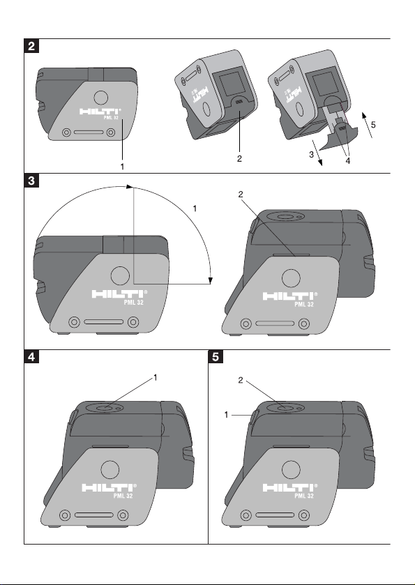
6.1 Inserting new batteries
-NOTE-
Do not use damaged batteries.
Do not mix old and new batteries. Do not mix batteries of different
makes or types.
1. Bring the two parts of the tool into the closed
position.
2. Press the battery compartment release button.
3. Pull the battery holder downwards out of the tool.
4. Replace the batteries.
-CAUTION-
Take care to observe correct polarity when inserting
the batteries.
5. Close the battery compartment. Check that it
engages securely.
Page 19

15
7. Operation
7. Operation
-NOTE-
The pendulum is locked when the tool is in the closed position (laser
beam blinks).
7.1 Operation
7.1.1 Bringing the tool into the operating position
1. Open the tool to the 90° or 180° position.
2. Bring the reference line into alignment with (parallel
to) the top edge of the base section.
-NOTE-
The pendulum is able to swing freely when the
reference line is parallel to the base section, when
the pendulum lockbutton is not pressed in and
when the tool is set up in a horizontal position
(≤ ±5°).
The laser beam blinks rapidly when the tool is
unable to level itself automatically.
7.1.2 Switching on the laser beam
To switch on only the horizontal beam:
1. Press the selector button once.
Page 20

16
7. Operation
To switch on only the vertical beam:
1. Press the selector button twice.
To switch on the horizontal and vertical beams:
1. Press the selector button three times.
7.1.3 Working in an inclined plane
1. Press the pendulum lockbutton (the pendulum is
then locked).
2. Switch on the horizontal and/or vertical beam.
-NOTE-
The laser beam blinks approx. every 2 seconds
when the pendulum is locked.
7.1.4 Switching the tool off
1. Press the selector button repeatedly (1-3 times
depending on previous operating mode) until the
laser beam is no longer visible and the LED no
longer lights.
-NOTE-
The tool switches itself off automatically after
approx. 15 minutes.
Page 21

17
7. Operation
7.1.5 Deactivating the automatic switch-off function
1. Press and hold the selector button (approx. 4
seconds) until the laser beam blinks three times in
confirmation.
-NOTE-
The tool will then operate until switched off by
pressing the selector button or until the batteries
are exhausted.
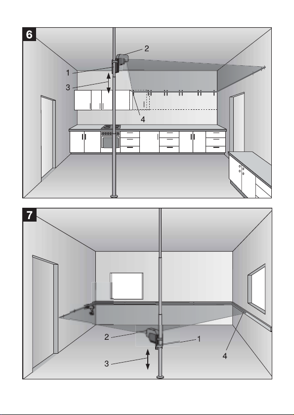
7.2. Examples of applications within the self-leveling range
7.2.1 Example 1:
Mounting shelves on a wall
1. Set up the tool on a telescopic pole, frame clamp or
tripod.
2. Switch on the horizontal beam.
3. Adjust the height of the tool until the beam is at the
correct position.
4. Mount the shelves along the laser line.
7.2.2 Example 2:
Mounting cable trays on a wall
1. Set up the tool on a telescopic pole or tripod.
2. Switch on the horizontal beam.
Page 22

18
7. Operation
3. Adjust the height of the tool until the beam is at the
correct position.
4. Mount the cable trays along the laser line.
7.2.3 Example 3:
Installing pipes vertically on a wall
1. Set up the tool on a level surface in front of
the wall.
2. Switch on the vertical beam.
3. Pivot the tool until the laser line projected on the
wall is at the position where the vertical pipe is
to be installed.
4. Install the pipe along the laser line.
7.2.4 Example 4:
Tiling a wall
1. Set up the tool on a telescopic pole or tripod.
2. Switch on the horizontal and vertical beams.
3. Adjust the position of the tool until the beams are at
the desired position.
4. Lay the tiles along the laser lines.
Page 23

19
7. Operation
7.3 Operating status indicators
7.3.1 LED
The LED doesn't light.
– The tool is switched off.
– The batteries are exhausted.
– The batteries are inserted incorrectly.
The LED lights constantly.
– The laser beam is switched on. The tool is in
operation.
The LED blinks.
– The batteries are almost exhausted.
– The temperature of the tool is above 40 °C (The laser
beam doesn't light).
7.3.2 Laser beam
The laser beam blinks twice every 10 seconds.
– The batteries are almost exhausted.
The laser beam blinks approx. every 2 seconds.
– The tool is in the closed position.
– The pendulum is locked.
The laser beam blinks rapidly.
– The tool cannot level itself automatically.
Page 24

20
8. Checks
8. Checks
8.1 Checking the horizontal line
8.1.1 Height accuracy (fig.
)
1. Place the tool on a level surface (floor).
2. Switch on the horizontal and vertical beams.
3. Set up the first target plate 20 cm in front of the
tool. The vertical laser line must just touch the left
edge of the first target plate. The height of the first
target plate must be adjusted so that the horizontal
beam strikes the plate exactly on the line printed on
it.
4. Set up the second target plate 5 meters beyond the
first plate. The vertical laser line must just touch the
right edge of the second target plate. The second
target plate must also be set up so that the
horizontal beam strikes the plate exactly on the line
printed on it.
5. Mark the position of the vertical beam on the floor
about 20 cm beyond the second target plate.
6. Move the tool to position 2 (see fig.
)
and place it on the mark. Adjust the height of the
tool so that the horizontal laser line strikes the
horizontal line printed on the plate. The vertical laser
line must be projected approximately between the
target plates, as before.
Page 25

21
8. Checks
7. The tool requires to be adjusted at a Hilti
repair center if the deviation in height (see fig.
)
exceeds 3 mm.
Page 26

22
8. Checks
8.1.2 Leveling accuracy )
1. Place the tool on a level surface (floor).
2. Switch on the horizontal beam.
3. Set up the target plates 2.5 m in front of the tool
and 3.5 m to the left and right, as shown in the
illustration, so that the horizontal laser line strikes
the horizontal lines printed on the target plates
exactly.
4. Move the tool to position 2 (see fig.
). It should
be the same distance from the target plates as
before.
5. The tool requires to be adjusted at a Hilti repair
center if the deviation exceeds 4.5 mm (see fig.
).
Page 27

23
8. Checks
Page 28

24
8. Checks
8.2 Checking the
vertical line (end to end) (fig.
)
1. Place the tool on a level surface (floor).
2. Switch on the vertical beam.
3. Set up the first target plate (vertically) at a distance
of 2.5 m from the tool, so that the vertical laser line
strikes the plate exactly on the line printed on it.
4. Set up the second target plate 1.8 m above the first
target plate (vertically above, plumb) so that the
vertical laser line also strikes this plate exactly on
the line printed on it.
5. Move the tool to the opposite side of the test setup
(mirrored) and secure it at a height of 1.8 m above
the first target plate so that the vertical laser line
also strikes this plate exactly on the line printed on
it .
6. The tool requires to be adjusted at a Hilti repair
center if the deviation exceeds 3 mm (see fig.
).
Page 29

25
8. Checks
Page 30

26
9. Care and maintenance
9. Care and maintenance
9.1 Cleaning and drying
–Blow dust off the lenses.
–Do not touch the glass with your fingers.
–Use only a clean, soft cloth for cleaning. If necessary,
moisten the cloth slightly with pure alcohol or a little
water.
-NOTE-
– Do not use any other liquids as these may damage the
plastic components.
– Observe the temperature limits when storing your
equipment. This is particularly important in summer if
the equipment is kept inside a motor vehicle (storage
temperature -20°C to +63°C / -4° to 145°F).
9.2 Storage
Remove the tool from its case if it has become wet. The
tool, its carrying case and accessories should be
cleaned and dried (max. temperature: 40°C / 104°F).
Repack the equipment only when it is completely dry.
Check the accuracy of the equipment before it is used
after a long period of storage or transportation. Remove
the batteries if the tool is not used over a long period.
Leaking batteries may damage the tool.
Page 31

27
9. Care and maintenance
9.3 Transportation
Use the Hilti shipping carton or packaging of equivalent
quality for transporting or shipping your equipment.
-NOTE-
Always remove the batteries before shipping.
Page 32

28
10. Troubleshooting
10. Troubleshooting
Fault Possible causes Remedy
The tool can't Batteries are exhausted. Replace the batteries.
be switched on. Batteries are inserted the wrong Insert the batteries
way round (incorrect polarity). correctly.
Battery compartment is Close the battery
not closed. compartment.
Tool or selector button is Bring the tool to a
defective. Hilti repair center.
Individual laser beams The laser source or laser Bring the tool to a
don't function. control is defective. Hilti repair center.
The tool can be switched The laser source or laser Bring the tool to a
on but no laser beam is control is defective. Hilti repair center.
visible.
Automatic leveling The surface on which the tool Set up the tool in a level
doesn't function. is set up is excessively inclined. position.
The pendulum is locked. Release the pendulum.
Extraneous light is too bright. Reduce extraneous light.
The tilt sensor is defective. Bring the tool to a
Hilti repair center.
The pendulum can't be The pendulum lockbutton Bring the tool to a
locked. is defective. Hilti repair center.
The base section cannot The base section (hinge) is dirty. Clean the base section.
be brought into the The base section is bent. Straighten or replace the
operating position. base section.
Page 33

29
11. Disposal
-CAUTION-
Improper disposal of the equipment may have serious
consequences:
– The burning of plastic components generates toxic
fumes which may present a health hazard.
– Batteries may explode if damaged or exposed to very
high temperatures, causing poisoning, burns, acid
burns or environmental pollution.
– Careless disposal may permit unauthorized and
improper use of the equipment, possibly leading to
serious personal injury, injury to third parties and
pollution of the environment.
Most of the materials from which Hilti tools or
appliances are manufactured can be recycled.
The materials must be correctly separated before they
can be recycled.
In many countries, Hilti has already made arrangements
for taking back old tools and appliances for recycling.
Ask Hilti customer service or your Hilti representative for
further information.
Should you wish to return the tool or appliance yourself
to a disposal facility for recycling, proceed as follows:
Dismantle the equipment as far as is possible without
special tools.
11. Disposal
Page 34

30
Separate the individual parts as follows:
Part / assembly Main material Recycling
Housing, toolbox Plastic, steel Plastics recycling,
scrap metal
Switch Plastic Plastics recycling
Screws, small parts Steel, aluminum, magnets Scrap metal
Electronics Various Electronics scrap
Batteries Alkaline manganese *
Soft case Woven synthetic material Plastics recycling
*
11. Disposal
Dispose of batteries in accordance with national
regulations.
Page 35

31
12. Warranty
12. Warranty
Hilti warrants that the tool supplied is free of defects in
material and workmanship. This warranty is valid as long
as the tool is operated and handled correctly, cleaned and
serviced properly and in accordance with the Hilti
operating instructions, all warranty claims are made
within 12 months (unless other mandatory national
regulations prescribe a longer minimum period) from the
date of sale (invoice date) and the technical system is
maintained. This means that only original Hilti
consumables, components and spare parts may be used
in the tool.
This warranty provides the free-of-charge repair or
replacement of defective parts only. Parts requiring repair
or replacement as a result of normal wear and tear are not
covered by this warranty.
Additional claims are excluded, unless stringent
national rules prohibit such exclusion. In particular,
Hilti is not obligated for direct, indirect, incidental or
consequential damages, losses or expenses in
connection with, or by reason of, the use of, or inability
to use the tool for any purpose. Implied warranties of
merchantability or fitness for a particular purpose are
specifically excluded.
Page 36

32
12. Warranty
Send the tool and/or related parts immediately upon
discovery of a defect to the local Hilti marketing
organization for repair or replacement.
This constitutes Hilti's entire obligation with regard to
warranty and supersedes all prior or contemporaneous
comments and oral or written agreements concerning
warranties.
Page 37

33
13. FCC statement (applicable in USA)
-CAUTION-
This equipment has been tested and found to comply with
the limits for a Class B digital device, pursuant to part 15
of the FCC rules.
These limits are designed to provide reasonable
protection against harmful interference in a residential
installation. This equipment generates, uses and may
radiate radio frequency energy and, if not installed and
used in accordance with the instructions, may cause
harmful interference to radio communications. However,
there is no guarantee that interference will not occur in a
particular installation. If this equipment does cause
harmful interference to radio or television reception,
which can be determined by turning the equipment off
and on, the user is encouraged to try to correct the
interference by taking the following measures:
–Reorient or relocate the receiving antenna.
–Increase the separation between the equipment and
receiver.
– Connect the equipment to an outlet on a circuit different
from that to which the receiver is connected.
– Consult your dealer or an experienced TV/radio
technician for assistance.
13. FCC statement (applicable in USA)
Page 38

34
Changes or modifications not expressly approved by Hilti
could limit the user's right to operate the equipment.
Labels
13. FCC statement (applicable in USA)
Page 39

35
14. EC declaration of conformity
14. EC declaration of conformity
Description: Line laser
Type designation: PML 32
Serial number: 000 00 001 – 500 00 000
Year of design: 2003
In conformance with requirements.
We declare, on our sole responsibility, that this product
complies with the following standards or standardization
documents:
EN 50081-1 and EN 61000-6-2 in accordance with
directive 89/336/EWG.
Hilti Corporation
Armin Spiegel
Leiter BU Positioning
Systems
Head of Positioning
Systems Business Unit
06 / 2003
Bodo Baur
Leiter Qualität Positioning
Systems
Quality Manager,
Positioning Systems
Business Unit
06 / 2003
Page 40

36
Page 41

Page 42

Hilti = reg. trademark of Hilti Corp., Schaan W2765 0703 2-Pos. 3 9 Printed in Liechtenstein © 2003
Right of technical and programme changes reserved S.E.&O.
377396
Hilti Corporation
FL-9494 Schaan
Tel.: +423 / 2342111
Fax: +423/234 2965
www.hilti.com
 Loading...