

Page 1
Title:
DS-K1100 Series Card Readers Connect
to DS-K2600 Series Access Controllers
by RS-485
Version:
v1.0
Date:
6/21/2017
Product:
Access Control Device
Page:
1 of 5
Card Reader
Access Control Terminal
DS-K1200MF
DS-K1T200MF/MF-C
DS-K1200EF
DS-K1T200EF/EF-C
Color
Description
Blue
RS-485 -
Yellow
RS-485 +
Red
PWR (DC +12V)
Black
GND (Power Grounding)
Black
GND (RS-485 Grounding)
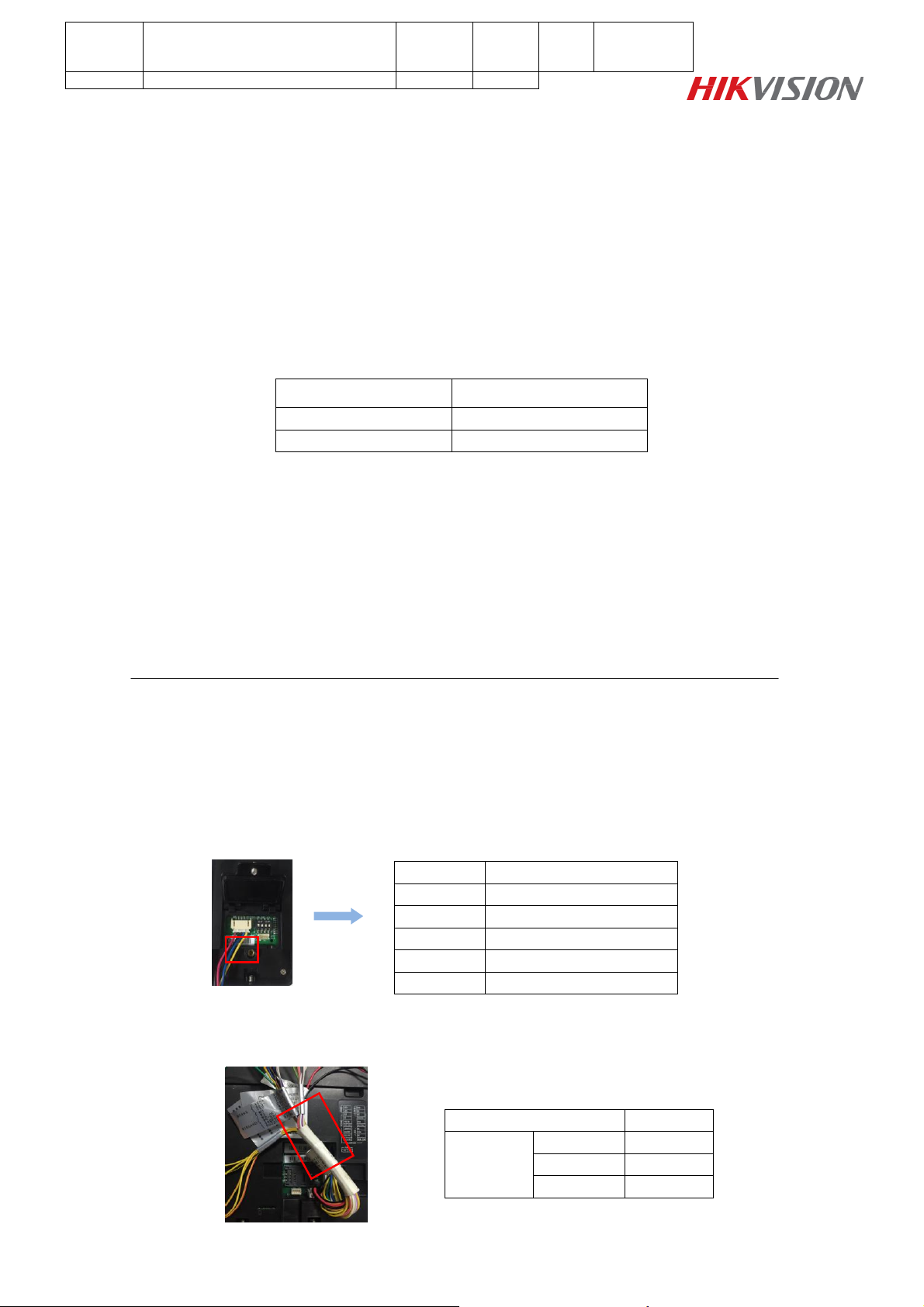
Interface
Color
RS485
RS485+
Yellow
RS485-
Blue
GND
Black
DS-K1200 Series Fingerprint Card Readers Connect to DS-
K1T200 Series Access Controll Terminal
Preparation
Connecting fingerprint card reader to access controll is mainly applied to swiping card or fingerprints to
open the door for entering and exiting. The models of card reader and access controller in this guide are
as below:
Note
If the model of access control terminal is DS-K1T105E/E-C or DS-K1T200EF/EF-C, we suggest
customers should match the following several card readers, such as DS-K1102E/EK, DS-K1107E/EK and
DS-K1108E/EK; you can find the same symbol ‘E’ in the access control terminal and card reader model
name, that means both devices can recognize the EM Card.
The ‘M’ access control terminal should be matched the ‘M’ card reader either, and they can recognize the
Mifare1 Card.
Notice
1. Please cut off power supply before wiring;
2. DS-K1200 Series Fingerprint Card Readers support private RS485 protocol; the details about RS-485
interface of fingerprint card reader are as below:
3. Correspondingly, there are RS485 interfaces in DS-K1T200 series access control terminal; the details
about RS-485 interface of DS-K1T200 series access control terminal are as below:
Page 2
Title:
DS-K1100 Series Card Readers Connect
to DS-K2600 Series Access Controllers
by RS-485
Version:
v1.0
Date:
6/21/2017
Product:
Access Control Device
Page:
2 of 3
Icon
Description
Represent 1 in binary mode
Represent 0 in binary mode
Power Input
RS485
RS485
Interface
RS485+
GND
RS485-/Blue
RS485+/Yellow
Power GND
12V/Red
External Power
Supply
RS485 GND
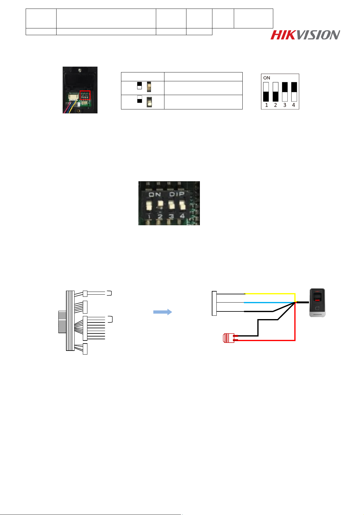
4. Please check the rear panel of card reader and unscrew it, you could find DIP switch module;
The No. of DIP switch from left to right is 1~4:
For example, the binary value of the above status is 0011.
Step 1: DIP Switch
Please set the DIP switch firstly before connecting the card reader, the binary value of the card reader is
0100, please set as the following picture;
Step 2: RS-485 Wiring
We recommend that customers use external power supply to fingerprint card reader.
Please connect card reader to door station as following picture:
Page 3

Title:
DS-K1100 Series Card Readers Connect
to DS-K2600 Series Access Controllers
by RS-485
Version:
v1.0
Date:
6/21/2017
Product:
Access Control Device
Page:
3 of 3
First Choice for Security Professionals
HIKVISION Technical Support
 Loading...