


Programming
Guide
HP 53131A/132A 225 MHz
Universal Counter

Programming Guide
This guide describes how to program the HP 53131A/132A 225 MHz Universal Counter. The information in this guide applies to instruments having the number prefix listed below, unless accompanied by a “Manual Updating Changes” package indicating otherwise.
SERIAL NUMBER PREFIX: 3546 to 3622 (HP 53131A) 3546 to 3646 (HP 53132A)
HP 53131A/132A 225 MHz
Universal Counter

ã Copyright Hewlett-Packard
Company 1996
All Rights Reserved. Reproduction, adaptation, or translations without prior written permission is prohibited, except as allowed under the copyright laws.
Printed: November 1996
Printed in USA
Manual part number 53131-90044
Certification
and Warranty
Certification
Hewlett-Packard Company certifies that this product met its published specification at the time of shipment from the factory. Hewlett-Packard further certifies that its calibration measurements are traceable to the United States National Institute of Standards and Technology (formerly National Bureau of Standards), to the extent allowed by the Institute's calibration facility, and to the calibration facilities of other International Standards Organization members.
Warranty
This Hewlett-Packard instrument product is warranted against defects in material and workmanship for a period of three years from date of shipment. During the warranty period, HewlettPackard Company will, at its option, either repair or replace products which prove to be defective.
For detailed warranty information, see back matter.
Safety Considerations
General
This product and related documentation must be reviewed for familiarization with this safety markings and instructions before operation.
This product is a safety Class I instrument (provided with a protective earth terminal).
Before Applying Power
Verify that the product is set to match the available line voltage and the correct fuse is installed. Refer to instructions in Chapter 1 of the Manual.
Safety Earth Ground
An uninterruptible safety earth ground must be provided from the mains power source to the product input wiring terminals or supplied power cable.
Warning Symbols That May
Be Used In This Book
Instruction manual symbol; the product will be marked with this symbol when it is necessary for the user to refer to the instruction manual.
Indicates hazardous voltages.
Safety Considerations (contd)
Indicates earth (ground) terminal.
or
Indicated terminal is connected to chassis when such connection is not apparent.
Indicates Alternating current.
Indicates Direct current.
WARNING
BODILY INJURY OR DEATH MAY RESULT FROM FAILURE TO HEED A WARNING. DO NOT PROCEED BEYOND A WARNING SIGN UNTIL THE INDICATED CONDITIONS ARE FULLY UNDERSTOOD AND MET.
CAUTION
Damage to equipment, or incorrect measurement data, may result from failure to heed a caution. Do not proceed beyond a CAUTION sign until the indicated conditions are fully understood and met.
For additional safety and acoustic noise information, see back matter.
Hewlett-Packard Company
Santa Clara Division
5301 Stevens Creek Boulevard
Santa Clara, California 95052-8059

Contents
1 Before You Start ...
Introduction 1-2
Differences Between Prior and Current Revisions of the HP 53131A/132A 1-3
HP 53131A Containing Firmware Revisions (3317, 3335, or 3402) 1-3
HP 53132A Time Interval Delay Arming 1-5
Getting Started 1-6
How to Use This Guide 1-6
New Users 1-6
What You Should Understand 1-6
Learning to Program the Counter 1-7
|
Experienced Programmers |
1-7 |
||
|
Applications 1-8 |
|
|
|
|
Programming Guide Contents |
1-9 |
||
|
Assumptions |
1-9 |
|
|
|
Related Documentation |
1-10 |
|
|
2 |
Command Summary |
|
|
|
|
Introduction |
2-2 |
|
|
|
Chapter Summary |
2-2 |
|
|
Front Panel to SCPI Command Maps 2-3
Some SCPI Syntax Conventions 2-3
Input Channels Conditioning Keys to SCPI
Command Map 2-4
Instrument Control, Utility, Recall, and Save & Print
Keys to SCPI Command Map 2-6
MEASURE Keys to SCPI Command Map 2-8
Gate & ExtArm Key to SCPI Command Map 2-10
Gate & ExtArm Key to SCPI Command Map — For HP 53131A (and HP 53132A With S/N Prefix
Below 3646) 2-13
LIMITS and MATH Keys to SCPI Command Map 2-16
Programming Guide |
iii |

Contents
|
Calibration Menu to SCPI Command Map |
2-18 |
|
|
||||||
|
HP 53131A/132A Command Summary |
2-20 |
|
|
||||||
|
SCPI Conformance Information |
2-20 |
|
|
|
|||||
|
IEEE 488.2 Common Commands |
2-21 |
|
|
|
|||||
|
HP 53131A/132A SCPI Subsystem Commands |
2-24 |
|
|||||||
|
Std/New Column |
2-24 |
|
|
|
|
|
|
|
|
|
Parameter Form Column |
2-24 |
|
|
|
|
|
|||
|
*RST Response 2-40 |
|
|
|
|
|
|
|
|
|
3 |
Programming Your Universal Counter for |
|
Remote |
|||||||
Operation |
|
|
|
|
|
|
|
|
|
|
|
Introduction 3-2 |
|
|
|
|
|
|
|
|
|
|
Chapter Summary |
|
3-2 |
|
|
|
|
|
|
|
|
Where to Find Some Specific Information |
3-2 |
|
|
||||||
|
Where to Find HP BASIC Programming Examples 3-3 |
|||||||||
|
Where to Find QuickBASIC Programming Examples |
3-3 |
||||||||
|
Where to Find Turbo C Programming Examples |
3-3 |
|
|||||||
|
Configuring the HP-IB |
3-4 |
|
|
|
|
|
|
|
|
|
To Set the HP-IB Mode and Address |
3-4 |
|
|
|
|||||
|
To Connect the Counter to a Computer 3-6 |
|
|
|||||||
|
Remote/Local Operation |
3-6 |
|
|
|
|
|
|||
|
Overview of Command Types and Formats |
3-7 |
|
|
||||||
|
Common Command Format |
3-7 |
|
|
|
|
|
|||
|
SCPI Command and Query Format |
3-7 |
|
|
|
|||||
|
Elements of SCPI Commands |
3-8 |
|
|
|
|
|
|||
|
Subsystem Command Syntax |
3-8 |
|
|
|
|
||||
|
Common Command Syntax |
3-8 |
|
|
|
|
|
|||
|
Abbreviated Commands |
3-9 |
|
|
|
|
|
|
||
|
Keyword Separator |
3-9 |
|
|
|
|
|
|
|
|
|
Optional Keyword |
|
3-9 |
|
|
|
|
|
|
|
|
Implied Channel (Optional Numeric Keyword Suffix) |
3-10 |
||||||||
|
Parameter Types |
3-11 |
|
|
|
|
|
|
|
|
|
Parameter Separator |
3-12 |
|
|
|
|
|
|
||
|
Query Parameters |
|
3-12 |
|
|
|
|
|
|
|
iv |
Programming Guide |

Contents
Suffixes 3-12 |
|
|
|
Suffix Elements |
|
3-12 |
|
Suffix Multipliers |
3-13 |
||
Command Terminator |
3-13 |
||
Using Multiple Commands |
3-14 |
||
Program Messages |
3-14 |
|
|
Program Message Syntax |
3-14 |
||
Overview of Response Message Formats 3-16 |
|||
Response Messages |
3-16 |
|
|
Response Message Syntax |
3-16 |
||
Response Message Data Types 3-17
Status Reporting 3-19
Status Byte Register and Service Request Enable
Register 3-21
Status Byte Register |
3-21 |
|
|
|
||
Service Request Enable Register |
3-23 |
|
|
|||
Standard Event Status Register Group |
3-24 |
|
|
|||
Standard Event Status Register |
3-24 |
|
|
|||
Standard Event Status Enable Register |
3-26 |
|
||||
Operation Status Register Group and Questionable Data/Signal Status |
||||||
Register Group 3-27 |
|
|
|
|
|
|
Condition Register |
3-28 |
|
|
|
||
Transition Filter |
3-28 |
|
|
|
||
Event Register |
3-29 |
|
|
|
|
|
Event Enable Register |
3-29 |
|
|
|
||
Operation Status Register Group |
3-30 |
|
|
|||
Questionable Data/Signal Status Register Group |
3-32 |
|||||
Command Settings for Optimizing Throughput |
3-35 |
|
||||
Commands to Set Counter for Optimal Throughput |
3-35 |
|||||
Typical Optimizing Throughput Results for Different Computers 3-37 |
||||||
How to Program the Counter for Status Reporting 3-38 |
||||||
Determining the Condition of the Counter 3-38 |
|
|||||
Resetting the Counter and Clearing the HP-IB |
|
|
||||
Interface— Example 1 |
|
3-38 |
|
|
|
|
Using the Standard Event Status Register to Trap an Incorrect HP-IB |
||||||
command— Example 2 |
3-39 |
|
|
|
||
Programming Guide |
v |

Contents
Event Status Register 3-39
Using the Questionable Data/Signal Status Register to Alert the Computer When Automatic Interpolator Calibration is Disabled— Example 3 3-39
Questionable Data Status Register |
3-40 |
|
|
Using the Operation Status Register to Alert the Computer When |
|||
Measuring has Completed— Example 4 |
3-40 |
|
|
Operation Status Register 3-40 |
|
|
|
How to Program the Counter to Display Results 3-43 |
|||
Configuring the Counter’s Display 3-43 |
|
|
|
Commands for Displaying Non-Scaled/Offset Results 3-43 |
|||
Commands for Displaying Scaled/Offset Results |
3-44 |
||
Commands for Displaying the Limit Graph |
3-44 |
|
|
Commands for Displaying Statistics Results |
3-44 |
||
Commands for Enabling and Disabling the Display |
3-45 |
||
How to Program the Counter to Synchronize Measurements 3-46
Synchronizing Measurement Completion |
3-46 |
|
||||
Resetting the Counter and Clearing the HP-IB Interface 3-46 |
||||||
Using the *WAI Command |
3-46 |
|
|
|
|
|
Using the *OPC? Command |
3-47 |
|
|
|
|
|
Using the *OPC Command to Assert SRQ |
3-48 |
|
||||
How to Program the Counter for Math/Limit |
|
|
|
|||
Operations 3-49 |
|
|
|
|
|
|
Updating Math and Limit Results Over HP-IB |
3-49 |
|||||
Using the Scale and Offset Over HP-IB |
3-50 |
|
|
|||
How to Program the Counter to Define Macros |
3-52 |
|
||||
Writing SCPI Programs |
3-55 |
|
|
|
|
|
Programming Examples |
3-58 |
|
|
|
|
|
Using HP BASIC 3-58 |
|
|
|
|
|
|
To Send a Double-Quoted String |
3-58 |
|
|
|||
To Send a Single-Quoted String |
3-58 |
|
|
|||
Using QuickBASIC |
3-59 |
|
|
|
|
|
Using Turbo C 3-59 |
|
|
|
|
|
|
List of the Programming Examples 3-59 |
|
|
|
|||
Easiest Way to Make a Measurement (HP BASIC) |
3-60 |
|||||
To Make a Frequency Measurement (HP BASIC) |
3-62 |
|||||
vi |
Programming Guide |

Contents
To Perform Limit Testing (HP BASIC) |
3-63 |
|
|
|
To Measure the Statistics of 50 Measurements |
|
|
||
(HP BASIC) |
3-64 |
|
|
|
To Use Limits to Filter Data Before Measuring Stats |
|
|
||
(HP BASIC) |
3-66 |
|
|
|
To Read and Store Calibration Information |
|
|
||
(HP BASIC) |
3-68 |
|
|
|
To Perform a Time Interval Calibration (HP BASIC) |
3-69 |
|
||
To Optimize Throughput (HP BASIC) 3-73 |
|
|
||
To Use Macros (HP BASIC) 3-75 |
|
|
|
|
To Make a Frequency Measurement (QuickBASIC) |
3-77 |
|
||
To Perform Limit Testing (QuickBASIC) |
3-78 |
|
|
|
To Measure the Statistics of 50 Measurements |
|
|
||
(QuickBASIC) |
3-80 |
|
|
|
To Use Limits to Filter Data Before Measuring Stats (QuickBASIC) |
3- |
|||
82 |
|
|
|
|
To Read and Store Calibration Data (QuickBASIC) |
3-85 |
|
||
To Optimize Throughput (QuickBASIC) |
3-86 |
|
|
|
To Use Macros (QuickBASIC) 3-88 |
|
|
|
|
To Make a Frequency Measurement (Turbo C) 3-91 |
|
|
||
To Use Limits to Filter Data Before Measuring Statistics (Turbo C) |
3- |
|||
93 |
|
|
|
|
To Optimize Throughput (Turbo C) 3-96
Programming Guide |
vii |

Contents
4 Command Reference
Introduction 4-2
:ABORt Command 4-4
:CALCulate Subsystems 4-5
:CALCulate[1] Subsystem 4-7
:CALCulate[1]:MATH Subtree 4-9
:CALCulate2 Subsystem 4-11
:CALCulate2:LIMit Subtree 4-12
:CALCulate3 Subsystem 4-19
:CALCulate3:AVERage Subtree 4-19
:CALCulate3:LFILter Subtree 4-23
:CALibration Subsystem 4-26
:CALibration:SECurity Subtree 4-28
:CONFigure Subsystem |
4-30 |
|
Device Clear 4-31 |
|
|
:DIAGnostic Subsystem |
4-32 |
|
:DISPlay Subsystem |
4-37 |
|
:FETCh Subsystem |
4-40 |
|
:FORMat Subsystem |
4-41 |
|
Group Execute Trigger (GET) 4-42 |
||
:HCOPy Subsystem |
4-43 |
|
:INITiate Subsystem |
4-44 |
|
:INPut[1|2] Subsystem |
4-48 |
|
:INPut3 Subsystem |
4-50 |
|
:MEASure Subsystem |
4-51 |
|
Measurement Instructions (:CONFigure, :FETCh, :MEASure, :READ) 4-52
Using :MEAsure 4-75
Using :CONFigure with :READ? 4-76
Using :CONFigure with :INITiate and :FETCh? 4-76 Firmware Revision Work-Around Commands 4-77
:MEMory Subsystem 4-79
[:SENSe] Subsystem 4-80
[:SENSe]:EVENt[1|2] Subtree 4-80
viii |
Programming Guide |
Contents
[:SENSe]:EVENt3 Subtree |
4-84 |
|
|
[:SENSe]:FREQuency Subtree |
4-85 |
|
|
[:SENSe]:FREQuency:ARM Subtree |
85 |
||
[:SENSe]:PHASe Subtree |
4-91 |
|
|
[:SENSe]:PHASe:ARM Subtree 4-91 |
|
||
[:SENSe]:ROSCillator Subtree |
4-92 |
|
|
[:SENSe]:TINTerval Subtree (HP 53131A and |
|||
HP 53132A With S/N Prefix Below 3646) |
4-95 |
||
[:SENSe]:TINTerval:ARM Subtree (HP 53131A and HP 53132A With S/N Prefix Below 3646) 4-95
[:SENSe]:TINTerval Subtree (HP 53132A With S/N Prefix 3646 and Above) 4-98
[:SENSe]:TINTerval:ARM:ESTART and :ESTOP Subtrees (HP 53132A With S/N Prefix 3646 and Above) 4-98
[:SENSe]:TOTalize Subtree 4-104 [:SENSe]:TOTalize:ARM Subtree 4-104
:STATus Subsystem 4-107
:STATus:OPERation Subtree 4-107
:STATus:QUEStionable Subtree 4-110
:SYSTem Subsystem 4-114
:SYSTem:COMMunicate Subtree |
4-114 |
|
||||
:TRACe Subsystem |
4-119 |
|
|
|
|
|
:TRIGger Subsystem |
4-121 |
|
|
|
||
*CAL? (Calibration Query) |
4-122 |
|
|
|||
*CLS (Clear Status Command) |
4-123 |
|
||||
*DDT <arbitrary block> (Define Device Trigger |
|
|||||
Command) |
4-124 |
|
|
|
|
|
*DMC <string>, <arbitrary block> |
|
|
||||
(Define Macro Command) |
4-125 |
|
|
|||
*EMC <NRf> (Enable Macro Command) 4-126 |
||||||
*EMC? (Enable Macro Query) |
4-126 |
|
||||
*ESE <NRf> (Standard Event Status Enable |
|
|||||
Command) |
4-127 |
|
|
|
|
|
*ESE? (Standard Event Status Enable Query) |
4-127 |
|||||
*ESR? (Event Status Register Query) |
4-128 |
|
||||
*GMC? <string> (Get Macro Contents Query) |
4-129 |
|||||
Programming Guide |
ix |

Contents
*IDN? (Identification Query) |
4-130 |
|
|
||
*LMC? (Learn Macro Query) |
4-131 |
|
|
||
*OPC (Operation Complete Command) |
4-132 |
||||
*OPC? (Operation Complete Query) |
4-133 |
||||
*OPT? (Option Identification Query) |
4-134 |
||||
*PMC (Purge Macro Command) |
4-135 |
|
|||
*RCL <NRf> (Recall Command) |
4-136 |
|
|||
*RST (Reset Command) |
4-137 |
|
|
|
|
*SAV <NRf> (Save Command) |
4-138 |
|
|
||
*SRE <NRf> (Service Request Enable Command) 4-139 |
|||||
*SRE? (Service Request Enable Query) |
4-139 |
||||
*STB? (Status Byte Query) |
4-140 |
|
|
||
*TRG (Trigger Command) |
4-141 |
|
|
||
*TST? (Self-Test Query) |
4-142 |
|
|
||
*WAI (Wait-to-Continue Command) |
4-143 |
||||
5 Errors
Introduction 5-2
Displaying Errors 5-2
Reading an Error 5-2
Error Queue 5-3
Error Types 5-4
No Error 5-4
Command Error 5-4
Execution Error 5-5
Deviceor Counter-Specific Error 5-5
Query Error 5-6
x |
Programming Guide |

1
Before You Start ...

Chapter 1 Before You Start ...
Introduction
Introduction
This programming guide contains programming information for the HP 53131A/132A Universal Counter.
This guide assumes you are familiar with the front-panel operation of the Counter. See the HP 53131A/132A Operating Guide for detailed information about frontpanel operation. You should use this programming guide together with the operating guide. Knowing how to control the Counter from the front panel and understanding the measurements you wish to perform makes the programming task much easier. The operating guide provides explanations and task procedures for all of the Counter ’s measurement functions, and contains the specifications for the Counter.
By sending Standard Commands for Programmable Instruments (SCPI) commands, all of the Counter ’s front-panel functions can be remotely operated via the Hewlett-Packard Interface Bus (HP-IB),
as well as the additional throughput optimizing function not available from the front panel.
This Counter programming commands conform to the Standard Commands for Programmable Instruments (SCPI) Standard Version 1992.0. The SCPI standard does not completely redefine how to program instruments over the HewlettPackard Interface Bus (HP-IB). However, it does standardize the structure and content of an instrument ’s command set to reflect the best programming practices developed by people using HP-IB. It also establishes standard command mnemonics for similar functions in all of the instruments that conform to the SCPI standard.
If you have programmed any HP instruments that have been released over the last few years, you will have seen a general trend toward the techniques specified in the SCPI standard. For example, several instruments are already using a hierarchy of commands that is similar to the command structure defined by the SCPI standard.
1-2 |
Programming Guide |

NOTE
Chapter 1 Before You Start ...
Programming Guide Contents
Differences Between Prior and Current Revisions
of the HP 53131A/132A
If you have an HP 53131A containing one of the prior firmware revisions (3317, 3335, or 3402), read the subsection below titled “HP 53131A Containing Firmware Revisions (3317, 3335, or 3402) ” to get an overview of the differences between the earlier firmware revisions and current firmware revision.
If you have an HP 53132A with a serial number prefix below 3646, read the subsection titled “HP 53132A Time Interval Delay Arming ” on page 1-5.
Note that throughout the guide, differences between the earlier and current firmware revisions are noted where applicable.
HP 53131A Containing Firmware Revisions (3317, 3335, or 3402)
There are four main areas that differ:
∙Calibrations
∙Measurements
∙Statistics
∙HP-IB Commands
Calibrations
If your Counter contains other than the current firmware revision, the following calibration features are different:
∙The calibration functions are in the Utility menu instead of the Calibration menu, which is accessed by pressing and holding the front-panel Utility key and then cycling POWER key.
∙Calibrations are not protected by a security code.
∙A calibration count does not exist to aid in monitoring the number of calibrations performed.
∙A more accurate Time Interval calibration (FINE TI) is not available.
See the section titled “Using the Calibration Menu” in Chapter 2 of the HP 53131A/132A Operating Guidefor details.
Programming Guide |
1-3 |

Chapter 1 Before You Start ...
Differences Between Prior and Current Revisions of the HP
53131A/132A
Measurements
If your Counter contains other than the current firmware revision, the following measurement capabilities are different:
∙Ratio channel selections Ratio 2 to 1 and Ratio 3 to 1
(for those counters equipped with Channel 3) are not available.
∙Ratio “AUTO-armed” does not automatically extends gate to capture sufficient edges.
If Channel 1 input frequency is less than approximately 10 Hz, the Ratio gate time is not extended to capture sufficient Channel 1 edges to produce a valid measurement. Default gate time is 100 msec, which is not long enough to capture two edges on a low-frequency signal. The user is required to extend the gate by switching to TIME arming, and selecting a gate time appropriately long.
∙Sensitivity for firmware revision below does not have adjusted controls to LO and MED sensitivity.
In some Counters that contained firmware revision 3317,
LO sensitivity fails to correctly count very high frequency signals.
Statistics
If your Counter contains other than statistics are not available using the Statistics menu (use Stats key).
the current firmware revision s, single-shot ON SINGLE: menu item found in the
HP-IB Commands
[:SENSe]:EVENt[1|2}:HYSTeresis:RELative
If your Counter contains firmware revision s 3402 and below, the input hysteresis command and query does not operate in the conventional way. That is, [:SENSe]:EVENt[1|2]:HYSTeresis:RELative sets high sensitivity when the parameter is MINimum or 0 percent, and sets low sensitivity when the parameter is MAXimum or 100 percent.
In the prior firmware revisions (3317, 3335, or 3402), MINimum or 0 percent corresponded to low sensitivity, and MAXimum or 100 percent corresponded to high sensitivity.
1-4 |
Programming Guide |

Chapter 1 Before You Start ...
Programming Guide Contents
:CONFigure:TOTalize:TIMed
:CONFigure:TOTalize:CONTinuous
:MEASure:TOTalize:TIMed?
If your Counter contains firmware revision s 3402 and below, the Totalize Measurement Instruction commands (shown above) are not available to disable auto-trigger.
In the firmware revisions 3402 and below, these commands enabled auto-trigger at the 50% level.
HP 53132A Time Interval De lay Arming
HP 53131A and HP 53132A Counters with a serial number prefix below 3646 are identical in their TI arming modes. Both only offer Time Interval Delay, where the STOP trigger of a time interval measurement can be delayed by a user -specified time.
Programming Guide |
1-5 |

Chapter 1 Before You Start ...
Getting Started
Getting Started
Before attempting to program the Counter, take some time to familiarize yourself with the content of this guide. The remainder of this chapter contains the following information:
∙An explanation of how you should use the programming guide based on your experience programming instruments and your testing requirements.
∙A description of the guide contents.
∙A statement of assumptions that are made in the guide.
∙A list of related documentation.
How to Use This Guide
How you use this guide depends upon how much you already know about programming instruments and how complex your measurement requirements are. Let’s start by establishing your programming background, and then discuss the type of measurements you want to perform.
New Users
What You Should Understand
As a new user, you should understand that you must have some understanding of a high-level language such as Pascal, BASIC, C,
or FORTRAN before you can use the command set defined in this guide to control the Counter. (In Chapter 3, “Programming Your Universal Counter for Remote Operation,” there are programming examples provided in HP BASIC, Microsoft ® QuickBASIC, and Borland ® Turbo C.) However, whatever language you use, command strings that control the Counter remain the same.
1-6 |
Programming Guide |

Chapter 1 Before You Start ...
Programming Guide Contents
Learning to Program the Counter
To learn how to program the Counter, perform the following:
∙Scan the summary tables in Chapter 2, “Command Summary ,”
to get a feeling for the number and structure of commands available to you.
∙Read and study map drawings in the section titled “Front Panel to SCPI Command Maps” in Chapter 2.
∙Read Chapter 3, “Programming Your Universal Counter for Remote Operation,” for an overview of the SCPI concepts as they relate to the HP 53131A/132A Universal Counter. Look at the flowcharts, which illustrate some of the decisions you must make when programming the Counter.
∙Read the section at the end of Chapter 3 titled “Programming Examples for Making Common Measurements,” which provides programming examples.
∙Modify some of the programming examples to select specific measurement functions. If the programs work, consider yourself an experienced programmer and use Chapter 4, “Command Reference,” as a reference for detailed information of all the Counter ’s SCPI commands.
Experienced Programmers
If you have programmed other HP-IB instruments, you will probably be familiar with many of the concepts and techniques discussed in this guide. Also, you will find that using the SCPI commands is very similar to using the older HP-IB commands. The main difference is the hierarchy of the subsystem commands. (However, this type of structure has been previously used on other instruments.)
Because the SCPI command set and some of the status reporting techniques are new, you may want to use the following sequence to learn the Counter programming requirements:
∙Look over the steps for a new user and perform any that you think are applicable to your current level of knowledge. In particular, look at the measurement techniques and examples provide in Chapter 3, “Programming Your Universal Counter for Remote Operation.”
∙Review the summary tables in Chapter 2, “Command Summary .” If this chapter contains sufficient information to get you started, write some programs to explore the Counter ’s capabilities. If you need additional information on any command, refer to the applicable command description in Chapter 4, “Command Reference.”
Programming Guide |
1-7 |

Chapter 1 Before You Start ...
How to Use This Guide
∙Review the remaining information in this guide to determine what is applicable to your programming requirements.
If you need more information than is contained in this guide, see the section in this chapter titled “Related Documentation.”
Applications
After you have read the appropriate information and written some measurement programs, you may want to expand the scope of your applications. The following two techniques are explained in detail:
∙If you are going to write interrupt-driven programs (or if you just want to determine the status of the Counter), read the section titled “Status Reporting” in Chapter 3.
∙If you are going to write programs to transfer data between the Counter and an external computer, read the sections titled “Overview of Response Message Formats,” and “Command Settings for Optimizing Throughput” in Chapter 3.
1-8 |
Programming Guide |
Chapter 1 Before You Start ...
Programming Guide Contents
Programming Guide Contents
The following information is contained in this guide:
∙Table of Contents
∙Chapter 1 (this chapter) ,“Before You Start,” is a preface that introduces you to the programming guide.
∙Chapter 2, “Command Summary ,” is a quick reference that summarizes the Counter’s programming commands. It provides you with front-panel to SCPI command maps, SCPI conformance information, and command summary tables.
∙Chapter 3, “Programming Your Universal Counter for Remote Operation,” describes how to set up the Counter for remote operation, briefly explains the SCPI elements and formats, describes status reporting, describes how to write programs,
and provides programming examples for each of the main tasks that you will want your Counter to perform.
∙Chapter 4, “Command Reference ,” is a dictionary that describes the SCPI subsystems and IEEE 488.2 Common commands.
∙Chapter 5, “Errors,” lists all the error messages the Counter can generate and what caused the error.
∙Index
Assumptions
This guide assumes the Counter is correctly installed and interfaced to an external computer. If it is not, see IEEE HP-IB Interconnection information in HewlettPackard Company, Tutorial Description of the Hewlett-Packard Interface Bus, 1987. (See the following section in this chapter titled “Related Documentation” for ordering information.)
As previously mentioned, this guide also assumes you are familiar with the frontpanel operation of the Counter. See the HP 53131A/132A Operating Guidefor detailed information about front-panel operation. Knowing how to control the Counter from the front panel and understanding the measurements you wish to perform makes the programming task much easier.
Programming Guide |
1-9 |

Chapter 1 Before You Start ...
Related Documentation
Related Documentation
This section contains a list of documentation related to the use of the Counter. Additional information that you may find useful can be found in the following publications:
1.HP 53131A/132A Operating Guide (HP Part Number 53131-90043)
2.Beginner’s Guide to SCPI (HP Part Number H2325-9000 2, July 1990 Edition).
3.Beginner’s Guide to SCPI, Barry Eppler (Hewlett-Packard Press, Addison-Wesley Publishing Co. 1991).
4.Standard Commands for Programmable Instruments (SCPI), Version 1992.0.
This standard is a guide for the selection of messages to be included in programmable instrumentation . It is primarily intended for instrument firmware engineers. However, you may find it useful if you are programming more than one instrument that claims conformance to the SCPI standard.
You can verify the use of standard SCPI commands in different instruments.
To obtain a copy of this standard, contact:
SCPI Consortium
8380 Hercules, Suite P3 La Mesa, CA 91942 Phone: (619) 697-8790 FAX: (619) 697-5955
5.The International Institute of Electrical Engineers and Electronic Engineers, IEEE Standard 488.1-1987, IEEE Standard Digital Interface for Programmable Instrumentation.
This standard defines the technical details required to design and build an HP-IB (IEEE 488.1) interface . This standard contains electrical specification and information on protocol that is beyond the need of most programmers. However, it can be useful to clarify formal definitions of certain terms used in related documents.
1-10 |
Programming Guide |

Chapter 1 Before You Start ...
Programming Guide Contents
To obtain a copy of this standard, write to:
The Institute of Electrical and Electronic Engineers Inc. 345 East 47th Street
New York, NY 10017 USA
6.The International Institute of Electrical Engineers and Electronic Engineers, IEEE Standard 488.2-1987, IEEE Standard Codes, Formats, Protocols, and Common Commands for Use with ANSI/IEEE Std 488.1- 1987 Programmable Instrumentation.
This standard defines the underlying message formats and data types used in SCPI. It is intended more for firmware engineers than for instrument users/programmers. However, it can be useful if you need to know the precise definition of specific message formats, data type, or common commands.
To obtain a copy of this standard, write to:
The Institute of Electrical and Electronic Engineers Inc. 345 East 47th Street
New York, NY 10017 USA
7.Hewlett-Packard Company,
BASIC 5.0/5.1 Interfacing Techniques Vol 2., Specific Interfaces, 1987.
This HP BASIC manual contains a good non-technical description of the HP-IB (IEEE 488.1) interface in Chapter 12, “The HP-IB Interface.” Subsequent revisions of HP BASIC may use a slightly different title for this manual or chapter.
This manual is the best reference on I/O for HP BASIC programmers.
To obtain a copy of this manual, contact your nearest Hewlett-Packard Sales office.
8.Hewlett-Packard Company, Tutorial Description of the Hewlett-Packard Interface Bus, 1987.
To obtain a copy of this manual, contact your nearest Hewlett-Packard Sales office.
Programming Guide |
1-11 |

Chapter 1 Before You Start ...
Related Documentation
1-12 |
Programming Guide |

2
Command Summary
A Quick Reference

Chapter 2 Command Summary
Introduction
Introduction
This chapter is a quick reference that summarizes the Counter ’s programming commands.
Chapter Summary
∙ Front Panel to SCPI Command Maps 1 |
pg. 2-3 |
– Some SCPI Syntax Conventions |
pg. 2-3 |
– Input Channels Conditioning Keys to SCPI |
|
Command Map |
pg. 2-4 |
– Instrument Control, Utility, Recall, and |
|
Save & Print Keys to SCPI Command Map |
pg. 2-6 |
– MEASURE Keys to SCPI Command Map |
pg. 2-8 |
– Gate & ExtArm Key to SCPI Command Map |
pg. 2-10 |
– Gate & ExtArm Key to SCPI Command Map |
|
For HP 53131A (and HP 53132A With |
|
S/N Prefix Below 3646) Time Interval |
|
Arming Commands |
pg. 2-13 |
– Gate & ExtArm Key to SCPI Command Map |
|
For HP 53132A (With S/N Prefix 3646 |
|
and Above) Time Interval Arming Commands |
pg. 2-14 |
– LIMITS and MATH Keys to SCPI Command |
|
Map |
pg. 2-16 |
– Calibration Menu to SCPI Command Map |
pg. 2-18 |
∙ HP 53131A/132A Command Summary 2 |
pg. 2-20 |
– SCPI Conformance Information |
pg. 2-20 |
– IEEE 488.2 Common Commands |
pg. 2-21 |
– HP 53131A/132A SCPI Subsystem Commands |
pg. 2-24 |
∙ *RST Response3 |
pg. 2-40 |
_______________________________
1The section titled “Front Panel to SCPI Command Maps,”provides maps that show the front-panel keys and their corresponding (or related) SCPI commands.
2The section titled “HP 53131A/132A Command Summary,”lists the IEEE 488.2 Common and the SCPI Subsystem commands in tables 2-1 and 2-2, respectively.
3The section titled *RST Response, lists the states of all of the commands that are affected by the *RST command in Table 2-3. This section also lists commands that are unaffected by *RST in
Table 2-4.
2-2 |
Programming Guide |

NOTE
Chapter 2 Command Summary
Front Panel to SCPI Command Maps
Front Panel to SCPI Command Maps
Figures 2-1 through 2-6 provide maps that show the one-to-one relationship of the front-panel keys and the SCPI commands. These maps should help with identifying commands if you are already familiar with the front panel.
Some SCPI Syntax Conventions
[ ] |
An element inside brackets is optional. Note, the brackets |
|
are NOT part of the command and should NOT be sent to |
|
the Counter. |
1 | 2 |
Means use either 1 or 2. |
<numeric_value> |
Means enter a number. |
SENSe |
Means you MUST use either all the upper case letters or |
|
the entire word. The lower case letters are optional. For |
|
example, SENS and SENSE are both valid. However, |
|
SEN is not valid. (Note SENSe is used here as an |
|
example, but this convention is true for all SCPI |
|
commands.) |
When you see quotation marks in the command ’s parameter
(shown in the “Parameter Form” column in Table 2-2), you must send the quotation marks with the command. Refer to the section titled “Using HP BASIC” in Chapter 3 (page 3-61) of this guide for details on how to use double quotes or single quotes to enclose the string parameter of a command.
Programming Guide |
2-3 |
Chapter 2 Command Summary
Front Panel to SCPI Command Maps
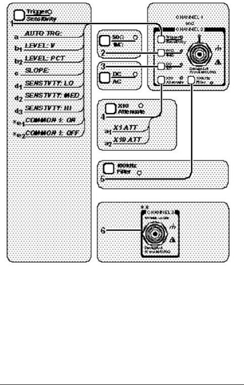
Input Channels Conditioning Keys to SCPI Command Map
_____________________________
*For TI 1 TO 2 (Time Interval measurements) only . **Channel 3 is optional.
Figure 2-1. Input Channels Conditioning Keys to SCPI Command Map (Part 1 of 2)
2-4 |
Programming Guide |

Chapter 2 Command Summary
Front Panel to SCPI Command Maps
Input Channels Conditioning Keys to SCPI Command Map (Cont.)
1 a. [:SENSe]:EVENt[1|2]:LEVel[:ABSolute]:AUTO ON|OFF
b1. [:SENSe]:EVENt[1|2]:LEVel[:ABSolute] <numeric_value> [V] b2. [:SENSe]:EVENt[1|2]:LEVel:RELative <numeric_value> [PCT]
c.[:SENSe]:EVENt[1|2]:SLOPe POSitive | NEGative
d1. [:SENSe]:EVENt[1|2]:HYSTeresis:RELative 100 * d2. [:SENSe]:EVENt[1|2]:HYSTeresis:RELative 50 d3. [:SENSe]:EVENt[1|2]:HYSTeresis:RELative 0 **
e1. [:SENSe]:EVENt2:FEED “[:]INPut[1]” e2. [:SENSe]:EVENt2:FEED “[:]INPut2”
2:INPut[1|2]:IMPedance <nume ric_value> [OHM]
3:INPut[1|2]:COUPling AC|DC
4a1. :INPut[1|2]:ATTenuation 1 a2. :INPut[1|2]:ATTenuation 10
5:INPut[1|2]:FILTer ON | OFF
6:INPut3:COUPling?
:INPut3:IMPedance?
__________________________
*Note, in firmware revisions 3317, 3335 and 3402, use 0.
**Note, in firmware revisions 3317, 3335 and 3402, use 100.
Figure 2-1. Input Channels Conditioning Keys to SCPI Command Map (Part 2 of 2)
Programming Guide |
2-5 |

Chapter 2 Command Summary
Front Panel to SCPI Command Maps
Instrument Control, Utility, Recall, and Save & Print Keys to SCPI Command Map
Figure 2-2. Instrument Control, Utility, Recall, and Save & Print Keys to SCPI Command Map (Part 1 of 2)
2-6 |
Programming Guide |
 Loading...