


 Loading...
hp procurve wireless AP 420 ww/na
Installation and Getting Started Guide

© Copyright 2003 Hewlett-Packard Company
All Rights Reserved.
This document contains information which is protected by copyright. Reproduction, adaptation, or translation without prior permission is prohibited, except as allowed under the copyright laws.
Publication Number
J8130-90001
July 2003
Applicable Products
hp procurve wireless AP 420 ww/na (J8131A/J8130A)
Disclaimer
The information contained in this document is subject to change without notice.
HEWLETT-PACKARD COMPANY MAKES NO WARRANTY OF ANY KIND WITH REGARD TO THIS MATERIAL, INCLUDING, BUT NOT LIMITED TO, THE IMPLIED WARRANTIES OF MERCHANTABILITY AND FITNESS FOR A PARTICULAR PURPOSE. Hewlett-Packard shall not be liable for errors contained herein or for incidental or consequential damages in connection with the furnishing, performance, or use of this material.
Hewlett-Packard assumes no responsibility for the use or reliability of its software on equipment that is not furnished by Hewlett-Packard.
Warranty
See the Customer Support/Warranty booklet included with the product.
A copy of the specific warranty terms applicable to your Hewlett-Packard products and replacement parts can be obtained from your HP Sales and Service Office or authorized dealer.
Safety
Before installing and operating these products, please read the “Installation Precautions” in chapter 2, “Installing the
Access Point 420ww/na”, and the safety statements in appendix C, “Safety and Regulatory Statements”.
Hewlett-Packard Company
8000 Foothills Boulevard, m/s 5552 Roseville, California 95747-5552 http://www.hp.com/go/hpprocurve

Contents
1 Introducing the hp procurve wireless AP 420 ww/na
Top of the Access Point . . . . . . . . . . . . . . . . . . . . . . . . . . . . . . . . . . . . . . . . 1-3
LEDs . . . . . . . . . . . . . . . . . . . . . . . . . . . . . . . . . . . . . . . . . . . . . . . . . . . . . . 1-3
Back of the Access Point . . . . . . . . . . . . . . . . . . . . . . . . . . . . . . . . . . . . . . 1-5
Antennas . . . . . . . . . . . . . . . . . . . . . . . . . . . . . . . . . . . . . . . . . . . . . . . . . . . 1-5
Console Port . . . . . . . . . . . . . . . . . . . . . . . . . . . . . . . . . . . . . . . . . . . . . . . 1-6
Network Port . . . . . . . . . . . . . . . . . . . . . . . . . . . . . . . . . . . . . . . . . . . . . . . 1-6
Power Connector . . . . . . . . . . . . . . . . . . . . . . . . . . . . . . . . . . . . . . . . . . . 1-6
Reset Button . . . . . . . . . . . . . . . . . . . . . . . . . . . . . . . . . . . . . . . . . . . . . . . 1-7
Access Point Features . . . . . . . . . . . . . . . . . . . . . . . . . . . . . . . . . . . . . . . . . 1-8
2 Installing the hp procurve wireless AP 420 ww/na
Included Parts . . . . . . . . . . . . . . . . . . . . . . . . . . . . . . . . . . . . . . . . . . . . . . . . 2-1
Installation Procedures . . . . . . . . . . . . . . . . . . . . . . . . . . . . . . . . . . . . . . . . 2-2
Summary . . . . . . . . . . . . . . . . . . . . . . . . . . . . . . . . . . . . . . . . . . . . . . . . . . . 2-2
Installation Precautions: . . . . . . . . . . . . . . . . . . . . . . . . . . . . . . . . . . . . . . 2-3
1. Prepare the Installation Site . . . . . . . . . . . . . . . . . . . . . . . . . . . . . . . . |
2-4 |
3. Verify the Access Point Passes the Self Test . . . . . . . . . . . . . . . . . . . 2-5 LED Behavior: . . . . . . . . . . . . . . . . . . . . . . . . . . . . . . . . . . . . . . . . . . 2-6
4. Mount the Access Point . . . . . . . . . . . . . . . . . . . . . . . . . . . . . . . . . . . . 2-7
Wall Mounting . . . . . . . . . . . . . . . . . . . . . . . . . . . . . . . . . . . . . . . . . . . 2-7
Horizontal Surface Mounting . . . . . . . . . . . . . . . . . . . . . . . . . . . . . . 2-9
5. Connect the Access Point to a Power Source . . . . . . . . . . . . . . . . . . 2-9
6. Connect the Network Cable . . . . . . . . . . . . . . . . . . . . . . . . . . . . . . . . 2-10
Using the RJ-45 Connectors . . . . . . . . . . . . . . . . . . . . . . . . . . . . . . 2-10
7. Position the Antennas on the Access Point . . . . . . . . . . . . . . . . . . . 2-10
8. (Optional) Connect a Console to the Access Point 420wl . . . . . . . 2-11 Terminal Configuration . . . . . . . . . . . . . . . . . . . . . . . . . . . . . . . . . . 2-11 Direct Console Access . . . . . . . . . . . . . . . . . . . . . . . . . . . . . . . . . . . 2-12
Sample Network Topologies . . . . . . . . . . . . . . . . . . . . . . . . . . . . . . . . . . 2-13
Ad Hoc Wireless LAN (no access point) . . . . . . . . . . . . . . . . . . . . . . . |
2-13 |
i

Infrastructure Wireless LAN . . . . . . . . . . . . . . . . . . . . . . . . . . . . . . . . . 2-14 Infrastructure Wireless LAN for Roaming Wireless PCs . . . . . . . . . . 2-15
3 Getting Started With Access Point Configuration
Recommended Minimal Configuration . . . . . . . . . . . . . . . . . . . . . . . . . . 3-1 Using the Command Line Interface . . . . . . . . . . . . . . . . . . . . . . . . . . . . 3-2 Where to Go From Here . . . . . . . . . . . . . . . . . . . . . . . . . . . . . . . . . . . . . . 3-6
Using the IP Address for Remote Access Point Management . . . . . 3-7 Starting a Telnet Session . . . . . . . . . . . . . . . . . . . . . . . . . . . . . . . . . . . . . 3-7 Starting a Web Browser Session . . . . . . . . . . . . . . . . . . . . . . . . . . . . . . . 3-7
4 Troubleshooting
Basic Troubleshooting Tips . . . . . . . . . . . . . . . . . . . . . . . . . . . . . . . . . . . . 4-1
Diagnosing with the LEDs . . . . . . . . . . . . . . . . . . . . . . . . . . . . . . . . . . . . . 4-3
Proactive Networking . . . . . . . . . . . . . . . . . . . . . . . . . . . . . . . . . . . . . . . . . 4-5
Hardware Diagnostic Tests . . . . . . . . . . . . . . . . . . . . . . . . . . . . . . . . . . . . 4-6
Testing the Access Point by Resetting It . . . . . . . . . . . . . . . . . . . . . . . . 4-6 Checking the Access Point’s LEDs . . . . . . . . . . . . . . . . . . . . . . . . . 4-6 Checking Console Messages . . . . . . . . . . . . . . . . . . . . . . . . . . . . . . . 4-6
Testing Twisted-Pair Cabling . . . . . . . . . . . . . . . . . . . . . . . . . . . . . . . . . . 4-7
Testing Access Point-to-Device Network Communications . . . . . . . . 4-7
Testing End-to-End Network Communications . . . . . . . . . . . . . . . . . . 4-7
Restoring the Factory Default Configuration . . . . . . . . . . . . . . . . . . . 4-8
Downloading New Access Point Software . . . . . . . . . . . . . . . . . . . . . . . 4-9
HP Customer Support Services . . . . . . . . . . . . . . . . . . . . . . . . . . . . . . . . . 4-9
Before Calling Support . . . . . . . . . . . . . . . . . . . . . . . . . . . . . . . . . . . . . . . 4-9
A Specifications
Physical . . . . . . . . . . . . . . . . . . . . . . . . . . . . . . . . . . . . . . . . . . . . . . . . . . A-1
Electrical . . . . . . . . . . . . . . . . . . . . . . . . . . . . . . . . . . . . . . . . . . . . . . . . . A-1
Environmental . . . . . . . . . . . . . . . . . . . . . . . . . . . . . . . . . . . . . . . . . . . . A-1
Acoustic ? . . . . . . . . . . . . . . . . . . . . . . . . . . . . . . . . . . . . . . . . . . . . . . . . . A-2
Connectors . . . . . . . . . . . . . . . . . . . . . . . . . . . . . . . . . . . . . . . . . . . . . . . . A-2
Safety . . . . . . . . . . . . . . . . . . . . . . . . . . . . . . . . . . . . . . . . . . . . . . . . . . . . A-2
ii

EMC Compliance (Class B) . . . . . . . . . . . . . . . . . . . . . . . . . . . . . . . . . . A-2
Radio Signal Certification . . . . . . . . . . . . . . . . . . . . . . . . . . . . . . . . . . . A-2
Immunity . . . . . . . . . . . . . . . . . . . . . . . . . . . . . . . . . . . . . . . . . . . . . . . . . A-2
Wireless . . . . . . . . . . . . . . . . . . . . . . . . . . . . . . . . . . . . . . . . . . . . . . . . . . A-3
B Access Point Port and Network Cables
Access Point Ports . . . . . . . . . . . . . . . . . . . . . . . . . . . . . . . . . . . . . . . . . |
B-1 |
Twisted-Pair Cables . . . . . . . . . . . . . . . . . . . . . . . . . . . . . . . . . . . . . . . . |
B-1 |
Twisted-Pair Cable/Connector Pin-Outs . . . . . . . . . . . . . . . . . . . . . . . |
B-2 |
Straight-Through Twisted-Pair Cable for |
|
10 Mbps or 100 Mbps Network Connections . . . . . . . . . . . . . . . . . . . . |
B-3 |
Cable Diagram . . . . . . . . . . . . . . . . . . . . . . . . . . . . . . . . . . . . . . . . . |
B-3 |
Pin Assignments . . . . . . . . . . . . . . . . . . . . . . . . . . . . . . . . . . . . . . . |
B-3 |
Crossover Twisted-Pair Cable for |
|
10 Mbps or 100 Mbps Network Connection . . . . . . . . . . . . . . . . . . . . . |
B-4 |
Cable Diagram . . . . . . . . . . . . . . . . . . . . . . . . . . . . . . . . . . . . . . . . . |
B-4 |
Pin Assignments . . . . . . . . . . . . . . . . . . . . . . . . . . . . . . . . . . . . . . . |
B-4 |
C Safety and EMC Regulatory Statements
Safety Information . . . . . . . . . . . . . . . . . . . . . . . . . . . . . . . . . . . . . . . . . . . |
C-1 |
Informations concernant la sécurité . . . . . . . . . . . . . . . . . . . . . . . . . . . |
C-2 |
Hinweise zur Sicherheit . . . . . . . . . . . . . . . . . . . . . . . . . . . . . . . . . . . . . . |
C-3 |
Considerazioni sulla sicurezza . . . . . . . . . . . . . . . . . . . . . . . . . . . . . . . . |
C-4 |
Consideraciones sobre seguridad . . . . . . . . . . . . . . . . . . . . . . . . . . . . . |
C-5 |
Safety Information (Japan) . . . . . . . . . . . . . . . . . . . . . . . . . . . . . . . . . . . |
C-6 |
Safety Information (China) . . . . . . . . . . . . . . . . . . . . . . . . . . . . . . . . . . . |
C-7 |
EMC Regulatory Statements . . . . . . . . . . . . . . . . . . . . . . . . . . . . . . . . . . |
C-8 |
U.S.A. . . . . . . . . . . . . . . . . . . . . . . . . . . . . . . . . . . . . . . . . . . . . . . . . . . . . C-8 |
|
Canada . . . . . . . . . . . . . . . . . . . . . . . . . . . . . . . . . . . . . . . . . . . . . . . . . . . |
C-8 |
Australia/New Zealand . . . . . . . . . . . . . . . . . . . . . . . . . . . . . . . . . . . . . . |
C-8 |
Japan . . . . . . . . . . . . . . . . . . . . . . . . . . . . . . . . . . . . . . . . . . . . . . . . . . . . . |
C-9 |
Korea . . . . . . . . . . . . . . . . . . . . . . . . . . . . . . . . . . . . . . . . . . . . . . . . . . . . . |
C-9 |
Taiwan . . . . . . . . . . . . . . . . . . . . . . . . . . . . . . . . . . . . . . . . . . . . . . . . . . . |
C-9 |
European Community . . . . . . . . . . . . . . . . . . . . . . . . . . . . . . . . . . . . . . |
C-10 |
iii

iv
1
Introducing the
hp procurve wireless AP 420 ww/na
The HP Procurve Access Point 420ww/na is a wireless repeater that seamlessly integrates with existing wired networks to support connectivity for mobile users or wireless workstations. This solution offers fast, reliable wireless connectivity with considerable cost savings over wired LANs. Just install enough wireless access points to cover your network area, plug wireless cards into your notebooks or install wireless adapters into your desktops, and start networking.
hp procurve wireless AP 420 ww/na (J8131A/J8130A)
procurve hp he ngtuc i Introd ww/na 420 AP wireless
1-1

Introducing the hp procurve wireless AP 420 ww/na
Introducing the hp procurve wireless AP 420 ww/na
Throughout this manual, this access point will be abbreviated as the hp procurve wireless AP 420 ww/na.
The AP 420 ww/na has one 10/100Base-TX RJ-45 port. This port also supports Power over Ethernet based on the IEEE 802.3af standard. The access point supports wireless connectivity at speeds up to 54 Mbps based on the IEEE 802.11g standard.
This access point is designed to be used primarily for connecting wireless clients to an enterprise network. This access point allows wireless clients to connect directly to each other, or to connect to other computers or network resources located on the wired network. In addition, the Access Point 420wl offers full network management capabilities.
This chapter describes your hp procurve wireless AP 420 ww/na including:
■Top and back of the access point
■Access point features
1-2

Introducing the hp procurve wireless AP 420 ww/na
Top of the Access Point
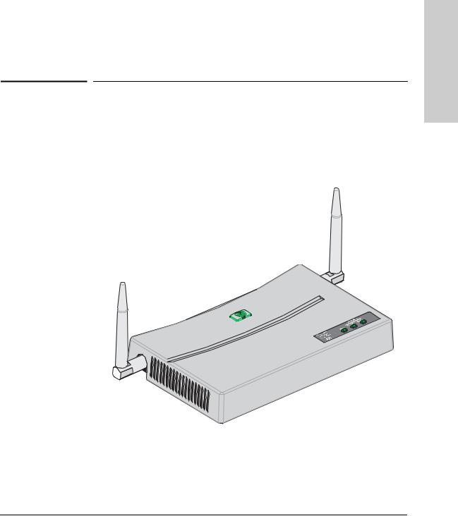
Top of the Access Point
hp procurve wireless AP 420 ww/na
Antennas
Power,
10/100-T Link,
and Wireless
Link LEDs
procurve hp he ngtuc i Introd ww/na 420 AP wireless
|
LEDs |
|
|
Table 1-1. Access Point LEDs |
|
|
|
|
Access Point |
State |
Meaning |
LEDs |
|
|
|
|
|
Power |
On |
The access point is receiving power. |
(green) |
Off |
The access point is NOT receiving power. |
|
||
|
Blinking* |
The access point is undergoing self test or downloading software. |
|
|
The self test and initialization are in progress after you have power cycled or reset |
|
|
the access point. The access point is not operational until this LED stops blinking. |
|
Blinking* |
A component of the access point has failed its self test. |
|
(prolonged) |
|
|
|
|
1-3

Introducing the hp procurve wireless AP 420 ww/na
Top of the Access Point
procurvethehpIntroducing ww/na420APwireless |
|
Access Point |
State |
Meaning |
|
LEDs |
|
|
|
|
|
|
|
|
|
|
|
|
|
|
|
10/100-T |
On (green) |
The LAN port is enabled and receiving a link indication from 100 Mbps device. |
|
|
|
On (amber) |
The LAN port is enabled and receiving a link indication from 10 Mbps device. |
|
|
|
Off |
The LAN port has no active network cable connected, or is not receiving a link beat. |
|
|
|
|
Otherwise, the port may have been disabled through the access point console, or the |
|
|
|
|
web browser interface. |
|
|
|
Blinking* |
The LAN port is transmitting or receiving traffic. |
|
|
|
|
|
|
|
Wireless |
On |
The wireless interface is enabled and receiving a link indication from a wireless client |
|
||||
|
|
|
Off |
The wireless interface is not receiving a link beat. Otherwise, the wireless interface |
|
|
|
|
may have been disabled through the access point console, or the web browser |
|
|
|
|
interface. |
|
|
|
Blinking* |
The wireless interface is transmitting or receiving traffic. |
|
|
|
|
|
|
|
* The blinking behavior is an on/off cycle once every 1.6 seconds, approximately. |
||
|
|
|
|
|
1-4
Introducing the hp procurve wireless AP 420 ww/na
Back of the Access Point
Back of the Access Point
hp procurve wireless AP 420 ww/na
Antennas
procurve hp he ngtuc i Introd ww/na 420 AP wireless
|
|
|
|
|
|
|
|
|
|
|
|
|
|
|
|
|
|
|
|
|
|
|
|
|
|
|
|
|
|
|
|
|
|
|
|
|
|
|
|
|
|
|
|
|
|
|
|
|
|
|
|
|
|
|
|
|
|
|
|
|
|
|
|
|
|
|
|
|
|
|
|
|
|
|
|
|
|
|
|
|
|
|
|
|
|
|
|
|
|
|
|
|
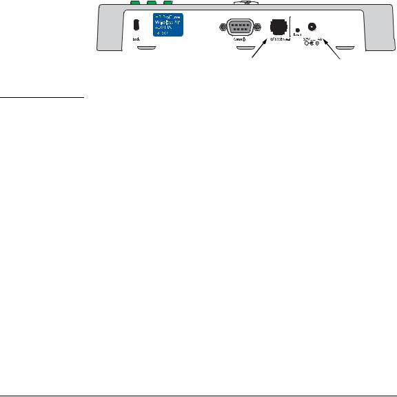
Console Port |
|
|
|
|
|
|
|
DC power connector |
|||
|
|
|
|
|
|
|
|
|
|
|
|
|
|
|
|
|
|
|
|
|
|
Reset buttons |
|
|
|||||
Lock |
|
|
|
|
|
|
|
|
|
|||||
|
|
|
10/100Base-TX RJ-45 |
|
|
|
|
|||||||
|
|
|
|
|
|
|
|
|
|
|
|
|||
|
|
|
|
|
|
|
|
|
|
|
|
|
||
|
|
|
|
port and PoE Input |
|
|
|
|
|
|
|
|
|
|
|
|
|
|
|
|
|
|
|
|
|
|
|
|
|
Antennas
The access point includes two antennas for wireless communications. The outbound signal transmitted from both antennas is identical, but only the best inbound signal received on one of the antennas is used. The antennas transmit the outgoing signal as a toroidal sphere, so the antennas should be adjusted to different angles to provide better coverage. For further information on positioning the antennas, see “Position the Antennas on the Access Point” on page 2-10.
Lock
The access point includes a Kensington security slot on the rear panel, marked “Lock”. You can prevent unauthorized removal the access point by wrapping the Kensington security cable (not provided) around an unmoveable object, inserting the lock into the slot, and turning the key.
1-5

Introducing the hp procurve wireless AP 420 ww/na
Introducing the hp procurve wireless AP 420 ww/na
Back of the Access Point
Console Port
This port is used to connect a console to the access point by using the serial cable supplied with the access point. This connection is described under “Connect a Console to the Access Point” in chapter 2, “Installing the Access Point 420wl”. The console can be a PC or workstation running a VT-100 terminal emulator, or a VT-100 terminal.
Network Port
The access point includes one 10/100Base-TX port. This port uses MDI (i.e., internal straight-through) pin configuration. You can therefore use straight-through twisted-pair cable to connect this port to most network interconnection device such as switch or router that provide MDI-X ports. However, if you need to connect the access point to a workstation or other device that only has MDI ports, then use crossover twisted-pair cable.
Ports on most HP switches have the “HP Auto MDIX” feature, which means that you can use either straight-through or crossover twisted-pair cables to connect the access point to these switches.
Refer to following section for information on supplying power to the access point’s network port from a network device, such as a switch, that provides Power over Ethernet (PoE).
|
Power Connector |
|
The AP 420 ww/na does not have a power switch; it is powered on when |
|
connected to the AC power adapter, and the power adapter is connected to |
|
an active AC power source. The access point automatically adjusts to any |
|
voltage between 100--240 volts and either 50 or 60 Hz. There are no voltage |
|
range settings required. |
|
|
C a u t i o n |
Use only the AC power adapter supplied with the access point. Use of other |
|
adapters, including adapters that came with other HP network products, may |
|
result in damage to the equipment. |
|
The access point may also receive Power over Ethernet (PoE) from a switch |
|
|
|
or other network device that supplies power over the network cable based on |
|
the IEEE 802.3af standard. |
1-6

Introducing the hp procurve wireless AP 420 ww/na
Back of the Access Point
Note that if the access point is connected to a PoE source device and also connected to a local power source through the AC power adapter, PoE will be disabled.
Reset Button
This button is used to restore the factory default configuration. When the Reset button is pressed, any configuration changes you may have made through the access point console, the web browser interface, and SNMP management are removed, and the factory default configuration is restored to the access point. For the specific method to restore the factory default configuration, see “Restoring the Factory Default Configuration” in chapter 4, “Troubleshooting” of this manual.
procurve hp he ngtuc i Introd ww/na 420 AP wireless
1-7

Introducing the hp procurve wireless AP 420 ww/na
Introducing the hp procurve wireless AP 420 ww/na
Access Point Features
Access Point Features
The wireless features of the Access Point 420ww/na include:
■supports up to 64 wireless clients.
■802.11g draft Compliant – interoperable with multiple vendors.
■provides seamless roaming within 802.11g draft WLAN environment.
■precise control over signal transmission power and data rate.
■advanced security through 64/128-bit WEP encryption, Wi-Fi Protected Access (WPA), 802.1x, remote authentication via RADIUS server, and MAC address filtering features to protect your sensitive data and authenticate only authorized users to your network.
■remote logging of system messages.
■time synchronization via SNTP server for message logs.
■supports PPP dial-in connection using standard dial-up program.
The other basic features of the Access Point 420ww/na include:
■one 10/100Base-TX RJ-45 port.
■supports Power over Ethernet based on the IEEE 802.3af standard.
■automatic learning of the network addresses in the access point’s address forwarding table.
■full-duplex operation for the 10/100 RJ-45 port when connected to other auto-negotiating devices.
■easy management of the access point through several available interfaces:
•console interface—a full featured, easy to use, VT-100 terminal interface that is especially good for out-of-band access point management or for Telnet access to the access point.
•web browser interface—an easy to use built-in graphical interface that can be accessed from common web browsers.
■support for one IEEE 802.1Q-compliant VLAN so the access point can join the appropriate logical grouping that fits your business needs.
■support for many advanced features to enhance network performance— for a description, see the Management and Configuration Guide, which is on the Documentation CD-ROM that is included with your access point.
■download of new access point software for product enhancements or bug fixes.
1-8

2
Installing the hp procurve wireless AP 420 ww/na
The HP Access Point 420ww/na is easy to install. It comes with an accessory kit that includes a bracket for mounting the access point on a wall. The bracket
is designed to allow mounting the access point in a variety of locations and orientations.
This chapter shows you how to install your Access Point 420ww/na.
Included Parts
The AP 420 ww/na has the following components shipped with it:
■hp procurve wireless AP 420 ww/na Installation and Getting Started Guide
(J8130-90001), this manual
■HP Procurve Product Documentation CD-ROM
(contains PDF file copies of the documentation for the
Access Point 420ww/na, including the Management and Configuration Guide)
■Console cable
■Customer Support/Warranty booklet
■Accessory kit (5064-2085?)
•one mounting bracket
•four 5/8-inch number 12 wood screws to attach the access point to a wall
•four plastic wall plugs for mounting on brick or concrete wall
•four rubber feet
■AC power adapter, one of the following:
Australia/New Zealand |
8120-6803 ? |
China |
8120-8377 |
Continental Europe |
8120-6802 |
Denmark |
8120-6806 |
Japan |
8120-6804 |
Switzerland |
8120-6807 |
United Kingdom/Hong Kong/Singapore |
8120-8709 |
United States/Canada/Mexico |
8120-6805 |
420 AP wireless |
e thg llin st aIn |
ww/na |
|
|
|
2-1

Installing the wireless AP 420 ww/na
Installing the hp procurve wireless AP 420 ww/na
Installation Procedures
Installation Procedures
Summary
Follow these easy steps to install your access point. The rest of this chapter provides details on these steps.
1.Prepare the installation site (page 2-4). Make sure that the physical environment into which you will be installing the access point is properly prepared, including having the correct network cabling ready to connect to the access point and having an appropriate location for the access point. Please see page 2-3 for some installation precautions.
2.Verify that the access point passes self test (page 2-5). This is a simple process of plugging the access point into a power source, or into a switch that provides Power over Ethernet, and observing that the LEDs on the access point’s front panel indicate correct access point operation.
3. Mount the access point (page 2-)7. The Access Point 420ww/na can be mounted on a wall, or on a horizontal surface.
4.Connect power to the access point (page 2-9). Once the access point is mounted, plug it into the nearby main power source, or into a switch that provides Power over Ethernet.
5.Connect to the network (page 2-10). Using the appropriate network cable, connect the access point to a network connection point, such as a switch.
6.Position the antennas on the access point (page 2-10). Position each antenna along a different axis to enhance signal coverage.
7.Connect a console to the access point (optional—page 2-11). You may wish to modify the access point’s configuration, for example, to configure an IP address so it can be managed using a web browser, from an SNMP network management station, or through a Telnet session. Configuration changes can be made easily by using the included console cable to connect a PC to the access point’s console port.
At this point, your access point is fully installed. See the rest of this chapter if you need more detailed information on any of these installation steps.
2-2

|
Installing the wireless AP 420 ww/na |
|
|
Installation Procedures |
|
|
|
|
|
Installation Precautions: |
|
|
Follow these precautions when installing your HP Access Point 420ww/na. |
|
|
|
|
C a u t i o n s |
■ Make sure that the power source circuits are properly grounded, then use |
|
|
the power adapter supplied with the access point to connect it to the |
|
|
power source. |
|
|
■ You can alternatively power the access point through a network connec- |
|
|
tion to a switch or other network connection device that provides Power |
|
|
over Ethernet. However, note that if the access point is connected to a |
|
|
power source, Power over Ethernet will be disabled. |
|
|
■ Use only the AC power adapter supplied with the access point. Use of |
|
|
other adapters, including adapters that came with other HP network |
|
|
products, may result in damage to the equipment. |
|
|
■ When installing the access point, note that the AC outlet should be near |
|
|
the access point and should be easily accessible in case the access point |
|
|
must be powered off. |
|
|
■ Ensure that the access point does not overload the power circuits, wiring, |
|
|
and over-current protection. To determine the possibility of overloading |
|
|
the supply circuits, add together the ampere ratings of all devices installed |
|
|
on the same circuit as the access point and compare the total with the |
|
|
rating limit for the circuit. The maximum ampere ratings are usually |
|
|
printed on the devices near the AC power connectors. |
|
|
■ Do not install the access point in an environment where the operating |
|
|
ambient temperature might exceed 55°C (131°F). |
|
|
■ Make sure the air flow around the sides of the access point is not |
|
|
restricted. |
|
|
|
|
|
|
|
|
|
|
AP wireless |
Installing |
420 |
the |
ww/na |
|
|
|
2-3

Installing the wireless AP 420 ww/na
Installing the wireless AP 420 ww/na
Installation Procedures
1. Prepare the Installation Site
■Cabling Infrastructure - Ensure that the cabling infrastructure meets the necessary network specifications. See the following table for cable types and lengths, and see appendix B, “Access Point Port and Network Cables” for more information:
Table 2-1. Summary of Cable Types to Use With the Access Point
Port Type |
Cable Type |
Length Limits |
|
|
|
Twisted-Pair Cables
10/100Base-TX |
• |
10 Mbps operation: |
|
|
Category 3, 4, or 5, 100-ohm unshielded |
|
|
twisted-pair (UTP) |
|
• |
100 Mbps operation: |
|
|
Category 5, 100-ohm UTP or shielded |
|
|
twisted-pair (STP) cable. |
100 meters
Note: Since the 10Base-T operation is through 10/100Base-TX ports, if you ever want to upgrade the ports to 100Base-TX, it would be best to cable the ports initially with category 5 cable.
The 10/100-Base-TX port on the
Access Point 420ww/na uses an MDI pin configuration, which requires you to use straight-through cable when connecting to another device that has an MDI-X port, or crossover cable when connecting to a device that has an MDI port. However, if the device to which you are connecting supports autoMDIX, then you can use either straightthrough or crossover cable.
■Installation Location - Before installing the access point, plan its location and orientation relative to other devices and equipment:
•Try to place the access point in the center of your wireless network. Normally, the higher you place the antenna, the better the performance. You may need to reposition the access point after testing the signal strength on several wireless clients to ensure that the access point’s location provides optimal reception throughout your office.
•In the back of the access point, leave at least 7.6 cm (3 inches) of space for the twisted-pair cabling and the power cord.
•On the sides of the access point, leave at least 7.6 cm (3 inches) for cooling.
2-4
Installing the wireless AP 420 ww/na
Installation Procedures
3. Verify the Access Point Passes the Self Test
Before mounting the access point in its network location, you should first verify that it is working properly by plugging it into a power source, or a switch that provides Power over Ethernet, and verifying that it passes its self test.
1.Connect a network cable from a PoE source device (such as a switch) to the RJ-45 jack on the back of the access point, or connect the power adapter supplied with the access point to the power connector on the back of the access point, and then into a properly grounded electrical outlet.
|
|
|
|
|
|
|
|
|
|
|
|
|
|
|
|
|
|
|
|
|
|
|
|
|
|
|
|
|
|
|
|
|
|
|
|
|
|
|
|
|
|
|
|
|
|
|
|
|
|
|
|
|
|
|
|
|
|
|
|
|
|
|
|
|
|
|
|
|
|
|
|
|
|
|
|
|
|
|
|
|
|
|
|
|
|
|
|
|
|
|
|
|
|
|
|
|
|
|
|
|
Connect network |
|
Or connect power adapter |
||||||
|
cable to PoE switch |
|
|
|
to the power connector |
||||
|
|
|
|
|
|
|
|
|
|
N o t e |
The AP 420 ww/na does not have a power switch. It is powered on when |
|
the power adapter is connected to the access point and to a power source, or |
|
when a network cable is connected to the access point and to a network device |
|
that provides Power over Ethernet. For safety, when connecting to an elec- |
|
trical outlet, the power outlet should be located near the access point. |
|
Use only the AC power adapter supplied with the access point. Use of other |
|
adapters, including adapters that came with other HP network products, may |
|
result in damage to the equipment. |
|
|
AP wireless |
Installing |
420 |
the |
ww/na |
|
|
|
2-5

Installing the wireless AP 420 ww/na
Installation Procedures
2.Check the LEDs on the access point as described below.
Installing the wireless AP 420 ww/na
Power LED |
Ethernet LED |
Wireless LED |
When the access point is powered on, it performs its diagnostic self test. The self test takes approximately 50 seconds to complete.
LED Behavior:
During the self test:
•The 10/100BASE-T and Wireless LEDs go off and then may come on again during phases of the self test. For the duration of the self test, the Power LED blinks.
When the self test completes successfully:
•The Power LED remains on.
•The 10/100BASE-T and Wireless LEDs on the top of the access point go into their normal operational mode:
–If the ports are connected to active network devices, the LEDs should be on.
–If the ports are not connected to active network devices, the LEDs will stay off.
If the LED display is different than what is described above, especially if the Power LED does not stop blinking, the self test has not completed correctly. Refer to chapter 4, “Troubleshooting” for diagnostic help.
2-6
Installing the wireless AP 420 ww/na
Installation Procedures
4. Mount the Access Point
After you have verified that the access point passes the self test, you are ready
to mount the access point in a stable location. The Access Point 420ww/na can be mounted in these ways:
■ on a wall
■ on a horizontal surface
Wall Mounting
You can mount the access point on a wall as shown in the illustrations on the next page.
C a u t i o n |
The access point should be mounted only to a wall or wood surface that is at |
|
|
least 1/2-inch plywood or its equivalent. |
|
|
1. |
Position the mounting bracket on the wall, and mark the holes. |
|
||
|
2. |
To mount the access point on a plastered brick or concrete wall, first drill |
|
|
four holes 22 mm deep and 3.5 mm in diameter, and press the included |
|
|
four wall plugs firmly into the drilled holes until they are flush with the |
|
|
surface of the wall. |
|
3. |
Set the four 5/8-inch number 12 wood screws in the holes, leaving about |
|
|
3 mm (0.12 in.) clearance from the wall. |
|
4. |
Position the mounting bracket over the wall screws, slide the bracket onto |
|
|
the screws, and then tighten down the screws. |
|
5. |
Slide the access point into the protruding slots on the back of the |
|
|
mounting bracket. The two retaining latches will slip into place over the |
|
|
back edge of the access point. |
|
6. |
To prevent unauthorized removal of the access point, you can use a |
|
|
Kensington Slim MicroSaver security cable (not included) to attach the |
|
|
access point to an immovable object. |
AP wireless |
Installing |
420 |
the |
ww/na |
|
|
|
2-7
Loading...