


 Loading...
HP color LaserJet 5500/5550 Printers
Service

HP Color LaserJet 5500/5550 Printers
Service Manual
© 2004 Copyright Hewlett-Packard
Development Company, L.P.
Reproduction, adaptation, or translation without prior written permission is prohibited, except as allowed under the copyright laws.
The information contained herein is subject to change without notice.
The only warranties for HP products and services are set forth in the express warranty statements accompanying such products and services. Nothing herein should be construed as constituting an additional warranty. HP shall not be liable for technical or editorial errors or omissions contained herein.
Part number: Q3713-90942
Edition 1, 9/2004
Trademark Credits
Adobe®, Adobe Photoshop®, and PostScript® are trademarks of Adobe Systems Incorporated.
Bluetooth is a trademark owned by its proprietor and used by Hewlett-Packard Company under license.
Corel® is a trademark or registered trademark of Corel Corporation or Corel Corporation Limited.
Linux is a U.S. registered trademark of Linus Torvalds.
Microsoft® is a U.S. registered trademark of Microsoft Corporation.
PANTONE® Pantone, Inc.’s checkstandard trademark for color.
UNIX® is a registered trademark of the Open Group.
Windows® is a U.S. registered trademark of Microsoft Corporation.
Table of contents
1 Printer description |
|
Model Configurations ................................................................................................................ |
2 |
The HP Color LaserJet 5500 series printer ........................................................................ |
2 |
Performance, memory, and other printer features .................................................................... |
4 |
Identification .............................................................................................................................. |
6 |
Model and serial numbers .................................................................................................. |
6 |
HP Color LaserJet 5500 models ........................................................................................ |
8 |
HP Color LaserJet 5550 models ........................................................................................ |
9 |
Printer specifications ............................................................................................................... |
10 |
Supply storage requirements (HP Color LaserJet 5500 series) ...................................... |
12 |
Product information ................................................................................................................. |
13 |
Product information .......................................................................................................... |
13 |
Electrical Specifications (HP Color LaserJet 5500 models) ............................................. |
13 |
Electrical specifications (HP Color LaserJet 5550 models) ............................................. |
14 |
Media requirements ................................................................................................................ |
16 |
Selecting print media ........................................................................................................ |
16 |
Media specifications ......................................................................................................... |
16 |
Supported media weights and sizes (HP Color LaserJet 5500 models) .......................... |
16 |
Supported paper weights and sizes (HP Color LaserJet 5550 models) .......................... |
19 |
Media specifications for 2-sided (duplex) printing ............................................................ |
22 |
Media to avoid .................................................................................................................. |
22 |
Media that may cause damage to the printer ................................................................... |
23 |
Printing on special media ................................................................................................. |
23 |
Transparencies ................................................................................................................. |
23 |
Printing on transparencies ................................................................................................ |
23 |
Glossy paper ..................................................................................................................... |
24 |
Colored paper ................................................................................................................... |
24 |
Heavy paper ..................................................................................................................... |
24 |
Printing images (HP Color LaserJet 5550 models) .......................................................... |
25 |
Envelopes ......................................................................................................................... |
25 |
Labels ............................................................................................................................... |
25 |
HP LaserJet Tough paper ................................................................................................ |
26 |
Preprinted forms and letterhead ...................................................................................... |
26 |
Recycled paper ................................................................................................................. |
26 |
Weight equivalence table ................................................................................................. |
27 |
Hewlett-Packard warranty statement ...................................................................................... |
28 |
Limited warranty for print cartridge life .................................................................................... |
29 |
Transfer unit and fuser warranty ............................................................................................. |
30 |
Declaration of Conformity ........................................................................................................ |
31 |
Safety information ................................................................................................................... |
32 |
Laser safety statement ..................................................................................................... |
32 |
Canadian DOC regulations ............................................................................................... |
32 |
EMI statement (Korea) ..................................................................................................... |
32 |
VCCI statement (Japan) ................................................................................................... |
33 |
Laser Statement for Finland ............................................................................................. |
34 |
Toner safety ............................................................................................................................ |
35 |
ENWW |
iii |
2 Service approach |
|
Chapter contents ..................................................................................................................... |
37 |
Service approach .................................................................................................................... |
38 |
Parts and supplies ................................................................................................................... |
39 |
Ordering parts ................................................................................................................... |
39 |
By phone: .......................................................................................................................... |
39 |
By mail: ............................................................................................................................. |
39 |
Ordering supplies .............................................................................................................. |
39 |
Ordering parts, supplies, and accessories over the Internet ............................................ |
39 |
Ordering directly through the embedded Web server (for printers with network |
|
connections) .................................................................................................................. |
39 |
Ordering directly through the HP Toolbox software (HP Color LaserJet 5550 |
|
model only) .................................................................................................................... |
40 |
Exchange program ........................................................................................................... |
40 |
Supplies ............................................................................................................................ |
40 |
World Wide Web ............................................................................................................... |
40 |
HP service parts information compact disc ...................................................................... |
41 |
HP support assistant compact disc .................................................................................. |
41 |
Customer care reseller sales and service support center ................................................ |
41 |
HP service agreements .................................................................................................... |
41 |
Other areas ....................................................................................................................... |
41 |
HP customer care ............................................................................................................. |
41 |
Ordering related documentation and software ................................................................. |
42 |
HP maintenance agreements ................................................................................................. |
44 |
On-site service agreements .............................................................................................. |
44 |
Priority on-site service ...................................................................................................... |
44 |
Next-day on-site service ................................................................................................... |
44 |
Weekly (volume) on-site service ...................................................................................... |
44 |
3 Installation and configuration |
|
Site requirements .................................................................................................................... |
47 |
Space requirements ................................................................................................................ |
48 |
500-sheet paper feeder dimensions ................................................................................. |
48 |
Printer stand dimensions .................................................................................................. |
48 |
Unpack the printer ................................................................................................................... |
49 |
Package contents ............................................................................................................. |
49 |
Unpacking the HP Color LaserJet 5500 series printer (for base models 5500n |
|
and 5500dn) .................................................................................................................. |
50 |
Unpacking the HP Color LaserJet 5500/5550dtn and 5500/5550hdn models ....................... |
54 |
Installing print cartridges for HP Color LaserJet 5500 series printers .................................... |
58 |
Installing print cartridges (HP Color LaserJet 5500 series models) ................................. |
58 |
Installing paper trays (HP Color LaserJet 5500 series printers) ...................................... |
60 |
Installing accessories (HP Color LaserJet 5500 series printers) ..................................... |
62 |
Installing optional printer stand (HP Color LaserJet 5500 series printers) ....................... |
65 |
Installing a new overlay (HP Color LaserJet 5500 models) ............................................. |
66 |
Installing a new control panel label (HP Color LaserJet 5550 models) ........................... |
67 |
Testing the printer operation ............................................................................................. |
69 |
Using PowerSave ............................................................................................................. |
69 |
Connecting to a computer ....................................................................................................... |
71 |
Parallel connections ......................................................................................................... |
71 |
USB configuration (HP Color LaserJet 5550 models) ...................................................... |
72 |
Auxiliary connection configuration (HP Color LaserJet 5550 models) ............................. |
72 |
Network connections ........................................................................................................ |
72 |
Enhanced I/O (EIO) configuration ........................................................................................... |
75 |
HP Jetdirect print servers ................................................................................................. |
75 |
iv |
ENWW |
Available enhanced I/O interfaces .................................................................................... |
75 |
NetWare networks ............................................................................................................ |
75 |
Windows and Windows NT networks ............................................................................... |
76 |
AppleTalk networks .......................................................................................................... |
76 |
LocalTalk configuration ..................................................................................................... |
76 |
LocalTalk network configuration ....................................................................................... |
76 |
UNIX/Linux networks ........................................................................................................ |
76 |
Wireless printing ...................................................................................................................... |
77 |
IEEE 802.11b standard .................................................................................................... |
77 |
Bluetooth ........................................................................................................................... |
77 |
Printer drivers .......................................................................................................................... |
78 |
Available drivers ............................................................................................................... |
78 |
Additional drivers .............................................................................................................. |
79 |
Select the right printer driver for your needs .................................................................... |
79 |
Printer driver Help ............................................................................................................. |
80 |
Software for Macintosh computers ......................................................................................... |
81 |
PPDs ................................................................................................................................. |
81 |
HP LaserJet Utility ............................................................................................................ |
81 |
Installing the printing system software .................................................................................... |
82 |
Installing Windows printing system software for direct connections ................................ |
82 |
Installing Windows printing system software for networks ............................................... |
83 |
To set up Windows-sharing to use the printer on a network ............................................ |
83 |
Installing Macintosh printing system software for networks ............................................. |
84 |
Installing Macintosh printing system software for direct connections (USB, |
|
HP Color LaserJet 5550 models) .................................................................................. |
85 |
Installing the software after the parallel or USB cable has been connected .................... |
86 |
Network configuration ............................................................................................................. |
88 |
Configuring Novell NetWare frame type parameters ....................................................... |
88 |
HP Web Jetadmin ............................................................................................................. |
89 |
UNIX ................................................................................................................................. |
89 |
Utilities .............................................................................................................................. |
89 |
Embedded Web server ..................................................................................................... |
90 |
Configuring TCP/IP parameters ....................................................................................... |
91 |
Setting network security on the printer .................................................................................... |
97 |
Locking the control panel .................................................................................................. |
97 |
Using an ASCII PJL escape sequence to set network security ....................................... |
98 |
4 Printer Maintenance |
|
Cleaning the printer and accessories .................................................................................. |
100 |
Cleaning spilled toner ..................................................................................................... |
100 |
Vacuum specifications .................................................................................................... |
100 |
Periodic cleaning ................................................................................................................... |
102 |
Cleaning the static discharge comb ............................................................................... |
102 |
Cleaning the OHT sensor ............................................................................................... |
103 |
Approximate replacement intervals for supply items ............................................................ |
105 |
ETB life under different circumstances ........................................................................... |
107 |
Locating supplies .................................................................................................................. |
108 |
Replacing supply items ......................................................................................................... |
109 |
Changing print cartridges ............................................................................................... |
109 |
Replacing the transfer unit (ETB) ................................................................................... |
111 |
Replacing the transfer unit when it is not at end of life .................................................. |
112 |
Replacing the fuser ......................................................................................................... |
113 |
Replacing the fuser when it is not at end of life .............................................................. |
114 |
Printer memory (HP Color LaserJet 5500 models) ............................................................... |
116 |
To print a configuration page .......................................................................................... |
116 |
ENWW |
v |
Installing memory and font DIMMs (for HP Color LaserJet 5500 models) |
.....................116 |
Installing DDR memory DIMMs (for HP Color LaserJet 5550 models) .......................... |
119 |
Enabling memory (HP Color LaserJet 5500 models) ..................................................... |
122 |
Enabling the language font DIMM (HP Color LaserJet 5550 models) ........................... |
122 |
Enabling the language font DIMM (HP Color LaserJet 5500 models) ........................... |
123 |
Checking DIMM installation (HP Color LaserJet 5500 models) ..................................... |
123 |
Installing an HP Jetdirect print server card .................................................................... |
123 |
5 Theory of operation |
|
Basic operation ..................................................................................................................... |
129 |
Operation sequence ....................................................................................................... |
129 |
Engine control system ........................................................................................................... |
131 |
DC controller circuit ........................................................................................................ |
131 |
Motors and fans .............................................................................................................. |
133 |
Fuser power supply circuit .............................................................................................. |
135 |
Heater temperature control ............................................................................................. |
136 |
Heater temperature control (HP Color LaserJet 5550 models) ...................................... |
137 |
Failure detection (HP Color LaserJet 5550 models) ...................................................... |
138 |
High-voltage power supply ............................................................................................. |
138 |
Low-voltage power supply .............................................................................................. |
139 |
Formatter system ............................................................................................................ |
140 |
PowerSave ..................................................................................................................... |
140 |
Input/Output .................................................................................................................... |
141 |
Printer memory ............................................................................................................... |
142 |
Read-only memory ......................................................................................................... |
142 |
Random-access memory ................................................................................................ |
142 |
Firmware DIMM (HP Color LaserJet 5500 models) ....................................................... |
142 |
Firmware compact flash (HP Color LaserJet 5550 models) .......................................... |
142 |
Nonvolatile memory ........................................................................................................ |
142 |
PJL overview .................................................................................................................. |
143 |
PML ................................................................................................................................. |
143 |
Control panel .................................................................................................................. |
143 |
Laser/scanner system ........................................................................................................... |
144 |
Scanner motor control .................................................................................................... |
145 |
Image formation system ........................................................................................................ |
146 |
Image formation process ................................................................................................ |
147 |
Print cartridges ................................................................................................................ |
149 |
Toner level detection ...................................................................................................... |
150 |
Electrostatic transfer/transport belt (ETB) unit ............................................................... |
154 |
Electrostatic latent image formation block ...................................................................... |
155 |
Development block ......................................................................................................... |
157 |
Transfer block ................................................................................................................. |
158 |
Fusing block .................................................................................................................... |
159 |
Fuser motor speed control .............................................................................................. |
160 |
Cleaning block ................................................................................................................ |
160 |
Calibration and cleaning ................................................................................................. |
161 |
Color plane registration calibration ................................................................................. |
165 |
Drum phase calibration ................................................................................................... |
166 |
Image stabilization control .............................................................................................. |
166 |
Pickup/feed system ............................................................................................................... |
169 |
Pickup/feed unit .............................................................................................................. |
172 |
Fuser/delivery unit .......................................................................................................... |
179 |
Duplex feed unit .............................................................................................................. |
180 |
500-sheet paper feeder ......................................................................................................... |
181 |
Pickup and feed operations ............................................................................................ |
181 |
vi |
ENWW |
6 Removal and replacement |
|
Introduction ............................................................................................................................ |
185 |
Removal and replacement strategy ................................................................................ |
185 |
Repair notices ................................................................................................................. |
185 |
Caution regarding electrostatic discharge (ESD) ........................................................... |
185 |
Required tools ................................................................................................................. |
185 |
Types of screws .............................................................................................................. |
186 |
Supplies ................................................................................................................................. |
188 |
Print cartridges and ETB ................................................................................................ |
189 |
Covers and external components ......................................................................................... |
190 |
Rear cover ...................................................................................................................... |
190 |
Top cover ........................................................................................................................ |
190 |
Rear top cover ................................................................................................................ |
191 |
Left cover ........................................................................................................................ |
192 |
Right cover ...................................................................................................................... |
193 |
Reinstallation tip ............................................................................................................. |
194 |
Multi-purpose tray (Tray 1) ............................................................................................. |
194 |
Front cover ...................................................................................................................... |
195 |
Control panel .................................................................................................................. |
196 |
Cassette cover ................................................................................................................ |
198 |
Internal components (front) ................................................................................................... |
199 |
Paper pickup unit ............................................................................................................ |
199 |
Cassette sensor PCB ..................................................................................................... |
200 |
Multi-purpose tray sensor PCB ...................................................................................... |
200 |
Paper pickup drive unit ................................................................................................. |
201 |
Lifter drive unit .............................................................................................................. |
202 |
Cassette (Tray 2) paper pickup and feed rollers ............................................................ |
204 |
Solenoid and clutch ........................................................................................................ |
205 |
Cassette separation roller ............................................................................................. |
206 |
Multi-purpose tray pickup roller ...................................................................................... |
207 |
Multi-purpose tray separation pad ................................................................................. |
208 |
Color registration detection unit ...................................................................................... |
208 |
Internal components (left side) .............................................................................................. |
210 |
DC controller shield ........................................................................................................ |
210 |
Environment sensor (HP Color LaserJet 5550 models) ................................................. |
210 |
Memory tag antenna PCBs ............................................................................................ |
211 |
E-label memory controller PCB ...................................................................................... |
217 |
DC controller PCB .......................................................................................................... |
218 |
Cassette paper size detection switches ......................................................................... |
219 |
Power supply fan ............................................................................................................ |
220 |
Internal components (rear) .................................................................................................... |
222 |
Formatter ........................................................................................................................ |
222 |
Low-voltage power supply .............................................................................................. |
223 |
Formatter case ................................................................................................................ |
225 |
Laser/scanner units ........................................................................................................ |
227 |
Internal components (right side) ........................................................................................... |
233 |
High-voltage power supply PCB ..................................................................................... |
233 |
Toner level detection PCB .............................................................................................. |
234 |
High-voltage contact blocks ............................................................................................ |
235 |
Door switch ..................................................................................................................... |
236 |
Internal components (top) ..................................................................................................... |
238 |
Discharging PCB ............................................................................................................ |
238 |
Fuser power supply PCB ................................................................................................ |
239 |
Fuser drive unit ............................................................................................................... |
240 |
Fuser inlet paper sensor ................................................................................................. |
243 |
Fuser delivery sensor and output bin full sensor ............................................................ |
244 |
ENWW |
vii |
Static discharge comb .................................................................................................... |
246 |
Formatter fan .................................................................................................................. |
247 |
Cartridge fan ................................................................................................................... |
247 |
Optional 500-sheet paper feeder .......................................................................................... |
249 |
Paper feeder left cover ................................................................................................... |
249 |
Paper feeder right cover ................................................................................................. |
250 |
Paper feeder pickup and feed rollers ............................................................................. |
251 |
Paper feeder separation roller ........................................................................................ |
251 |
Paper feeder pickup unit ................................................................................................. |
251 |
Paper feeder lifter drive unit ......................................................................................... |
253 |
Paper feeder length and width detection switches ....................................................... |
254 |
Paper feeder pickup clutch ............................................................................................. |
255 |
Paper feeder PCB .......................................................................................................... |
256 |
7 Troubleshooting |
|
Introduction ............................................................................................................................ |
260 |
Troubleshooting process ....................................................................................................... |
261 |
Pre-troubleshooting checklist ......................................................................................... |
261 |
Troubleshooting flowchart .............................................................................................. |
262 |
Troubleshooting flowchart (continued) ........................................................................... |
264 |
Troubleshooting power-on .............................................................................................. |
264 |
Printer error troubleshooting ................................................................................................. |
266 |
Status messages ............................................................................................................ |
266 |
Warning messages ......................................................................................................... |
266 |
Error messages .............................................................................................................. |
266 |
Critical error messages ................................................................................................... |
266 |
Alphabetical printer messages .............................................................................................. |
267 |
Numerical printer messages ................................................................................................. |
295 |
Replacement parts configuration (HP Color LaserJet 5550 models) ................................... |
328 |
Both the formatter and DC controller .............................................................................. |
328 |
Formatter (new or previously installed in another printer) .............................................. |
328 |
DC controller (new or previously installed in another printer) ........................................ |
329 |
Paper path troubleshooting ................................................................................................... |
330 |
Jams ............................................................................................................................... |
330 |
Jam locations .................................................................................................................. |
330 |
Jam locations by error message .................................................................................... |
330 |
Jam recovery .................................................................................................................. |
332 |
Avoiding paper jams ....................................................................................................... |
333 |
Persistent jams ............................................................................................................... |
334 |
Basic troubleshooting for paper jams ............................................................................. |
334 |
Data collection ................................................................................................................ |
334 |
General paper path troubleshooting ............................................................................... |
335 |
Paper path checklist ....................................................................................................... |
335 |
Paper transport troubleshooting ............................................................................................ |
341 |
Paper is wrinkled or folded ............................................................................................. |
341 |
Image formation troubleshooting .......................................................................................... |
343 |
Print quality problems associated with media ................................................................ |
343 |
Overhead transparency defects ..................................................................................... |
343 |
Print quality problems associated with the environment ................................................ |
344 |
Print quality problems associated with jams .................................................................. |
344 |
Print quality troubleshooting pages ................................................................................ |
344 |
Understanding color variations ....................................................................................... |
344 |
Print quality defect chart ........................................................................................................ |
350 |
Image defects ........................................................................................................................ |
356 |
Light image ..................................................................................................................... |
357 |
viii |
ENWW |
Light color ....................................................................................................................... |
357 |
Dark image ..................................................................................................................... |
358 |
Dark color ....................................................................................................................... |
358 |
Completely blank image ................................................................................................. |
359 |
All black or solid color ..................................................................................................... |
359 |
Dots in vertical lines ........................................................................................................ |
360 |
Dirt on back of paper ...................................................................................................... |
360 |
Dirt on front of paper ....................................................................................................... |
361 |
Vertical lines ................................................................................................................... |
361 |
White vertical lines .......................................................................................................... |
361 |
Horizontal lines ............................................................................................................... |
362 |
White horizontal lines ..................................................................................................... |
362 |
Missing color ................................................................................................................... |
363 |
Blank spots ..................................................................................................................... |
363 |
Poor fusing ...................................................................................................................... |
363 |
Distortion or blurring ....................................................................................................... |
364 |
Smearing ........................................................................................................................ |
365 |
Misplaced image ............................................................................................................. |
365 |
Repetitive defects troubleshooting ........................................................................................ |
366 |
Interface troubleshooting ...................................................................................................... |
369 |
Communications checks ................................................................................................. |
369 |
EIO troubleshooting ........................................................................................................ |
369 |
AUTOEXEC.BAT standard configurations ..................................................................... |
369 |
Printer Job Language (PJL) commands ........................................................................ |
370 |
Control panel troubleshooting ............................................................................................... |
372 |
Printing a menu map ...................................................................................................... |
372 |
Information menu ............................................................................................................ |
373 |
Paper handling menu ..................................................................................................... |
374 |
Configure device menu ................................................................................................... |
374 |
Printing menu .................................................................................................................. |
375 |
Print quality menu ........................................................................................................... |
376 |
System setup menu ........................................................................................................ |
377 |
I/O menu ......................................................................................................................... |
379 |
Resets menu ................................................................................................................... |
380 |
Diagnostics menu ........................................................................................................... |
380 |
Service menu .................................................................................................................. |
381 |
Tools for troubleshooting ...................................................................................................... |
383 |
Embedded Web server ................................................................................................... |
383 |
To access the embedded Web server ............................................................................ |
383 |
Information tab ................................................................................................................ |
384 |
Settings tab ..................................................................................................................... |
384 |
Networking tab ................................................................................................................ |
385 |
Other links ....................................................................................................................... |
385 |
Using the HP Toolbox (HP Color LaserJet 5550 models) .............................................. |
385 |
Printer Status and Alerts software .................................................................................. |
388 |
To choose which status messages appear .................................................................... |
389 |
To view status messages and information ..................................................................... |
389 |
Printer configuration page .............................................................................................. |
389 |
Supplies status page ...................................................................................................... |
391 |
Usage page .................................................................................................................... |
392 |
Event log ......................................................................................................................... |
394 |
Print the file directory page ................................................................................................... |
395 |
Print the PCL font list page ................................................................................................... |
396 |
Print the PS font list page ..................................................................................................... |
397 |
Print the RGB samples page (HP Color LaserJet 5550 models) ......................................... |
398 |
Print the CMYK samples page (HP Color LaserJet 5550 models) ....................................... |
399 |
ENWW |
ix |
Diagnostics ............................................................................................................................ |
400 |
LED diagnostics .............................................................................................................. |
400 |
Engine diagnostics ......................................................................................................... |
402 |
Diagnostics from the control panel ................................................................................. |
403 |
Test pages ............................................................................................................................. |
415 |
Engine test page ............................................................................................................. |
415 |
Formatter test page ........................................................................................................ |
415 |
Engine resets ........................................................................................................................ |
416 |
Cold reset ....................................................................................................................... |
416 |
NVRAM initialization ....................................................................................................... |
416 |
Hard disk initialization ..................................................................................................... |
417 |
Calibration bypass .......................................................................................................... |
417 |
Calibrate now .................................................................................................................. |
417 |
Full calibrate now (HP Color LaserJet 5550 models) ........................................................... |
418 |
Quick calibrate now (HP Color LaserJet 5550 models)......................................................... |
419 |
Service menu ........................................................................................................................ |
420 |
Accessing the Service menu .......................................................................................... |
420 |
Clear event log ................................................................................................................ |
420 |
Total page count ............................................................................................................. |
420 |
Transfer kit count ............................................................................................................ |
420 |
Fuser kit count ................................................................................................................ |
420 |
Serial number ................................................................................................................. |
420 |
Service ID ....................................................................................................................... |
421 |
Restoring the Service ID ................................................................................................. |
421 |
Converting the Service ID to an actual date ................................................................... |
421 |
Cold reset paper ............................................................................................................. |
421 |
Diagrams ............................................................................................................................... |
422 |
Main parts ....................................................................................................................... |
422 |
Switches ......................................................................................................................... |
424 |
Solenoid and clutch ........................................................................................................ |
425 |
Motors and fans .............................................................................................................. |
426 |
PCBs ............................................................................................................................... |
427 |
DC controller PCB .......................................................................................................... |
428 |
Connectors ..................................................................................................................... |
429 |
500-sheet paper feeder connectors ............................................................................... |
432 |
General circuit diagram .................................................................................................. |
433 |
500-sheet paper feeder circuit diagram .......................................................................... |
434 |
8 Parts and diagrams |
|
Introduction ............................................................................................................................ |
436 |
Ordering parts ....................................................................................................................... |
437 |
Supplies and accessories ............................................................................................... |
437 |
Common fasteners ......................................................................................................... |
442 |
Illustrations and parts lists (printer) ....................................................................................... |
444 |
Illustrations and parts lists (500-sheet paper feeder) ........................................................... |
494 |
Alphabetical parts list............................................................................................................. |
508 |
Numerical parts list................................................................................................................. |
517 |
Index |
|
x |
ENWW |
List of tables
Table 1-1. |
Model configurations ......................................................................................... |
2 |
Table 1-2. |
Features ............................................................................................................ |
4 |
Table 1-3. |
Model names and numbers .............................................................................. |
7 |
Table 1-4. |
Physical dimensions (HP Color LaserJet 5500 models) ................................. |
10 |
Table 1-5. |
Physical dimensions (HP Color LaserJet 5550 models) ................................. |
10 |
Table 1-6. |
Acoustic emissions (HP Color LaserJet 5500 ................................................. |
10 |
Table 1-7. |
Acoustic emissions (HP Color LaserJet 5550 models) ................................... |
11 |
Table 1-8. |
The electrical specifications table lists the electrical specifications |
|
|
required to run the printer safely. .................................................................... |
11 |
Table 1-9. |
Power Consumption (average in watts) (HP Color LaserJet 5550 |
|
|
models) ............................................................................................................ |
11 |
Table 1-10. |
Supply storage requirements .......................................................................... |
12 |
Table 1-11. |
Printer functions .............................................................................................. |
13 |
Table 1-12. |
Electrical specifications (HP LaserJet 5500 models) ...................................... |
13 |
Table 1-13. |
Electrical specifications and requirements ...................................................... |
14 |
Table 1-14. |
Power consumption ......................................................................................... |
14 |
Table 1-15. |
Operating environment specifications ............................................................. |
14 |
Table 1-16. |
Tray 1 (multi-purpose tray) supported media specifications ........................... |
16 |
Table 1-17. |
Tray 2, Tray 3, and Tray 4 supported media specifications ............................ |
18 |
Table 1-18. |
Tray 1 paper sizes and types .......................................................................... |
19 |
Table 1-19. |
Tray 2 and optional Trays 3, 4, and 5 (5550 model only) paper sizes |
|
|
and types ......................................................................................................... |
21 |
Table 1-20. |
Automatic two-sided printing (duplexing)1 ....................................................... |
22 |
Table 1-21. |
Printing on transparencies .............................................................................. |
23 |
Table 1-22. |
Paper specifications ........................................................................................ |
24 |
Table 1-23. |
Weight equivalence table ................................................................................ |
27 |
Table 2-1. |
Printer repair normally begins by using the printer’s internal |
|
|
diagnostics and the three-step process below. ............................................... |
38 |
Table 2-2. |
Related documentation and software ............................................................. |
42 |
Table 3-1. |
Available printer drivers ................................................................................... |
79 |
Table 3-2. |
Components and utilities ................................................................................. |
91 |
Table 3-3. |
Printer security levels ..................................................................................... |
97 |
Table 4-1. |
Cleaning the printer ...................................................................................... |
100 |
Table 4-2. |
Approximate replacement intervals for supply items .................................... |
105 |
Table 5-1. |
Basic operation sequence ............................................................................. |
130 |
Table 5-2. |
Function of motors and fans ......................................................................... |
134 |
Table 5-3. |
Calibration timing and duration ..................................................................... |
161 |
Table 5-4. |
Cleaning timing and duration ........................................................................ |
162 |
Table 5-5. |
Cassette paper size detection/cassette detection ........................................ |
173 |
Table 5-6. |
Feed speed according to media .................................................................... |
178 |
Table 6-1. |
Types of screws ............................................................................................ |
186 |
Table 6-2. |
Approximate replacement intervals for supply items .................................... |
188 |
Table 7-1. |
Pre-troubleshooting checklist ........................................................................ |
261 |
Table 7-2. |
Alphabetical printer messages (HP Color LaserJet 5500 models) ............... |
267 |
Table 7-3. |
Alphabetical printer messages (HP Color LaserJet 5550 models) ............... |
281 |
Table 7-4. |
Numerical printer messages (HP Color LaserJet 5500 models) .................. |
295 |
ENWW |
xi |
Table 7-5. |
Numerical printer messages (HP Color LaserJet 5550 models) .................. |
312 |
Table 7-6. |
Error messages and associated jam locations ............................................. |
331 |
Table 7-7. |
Common causes of paper jams .................................................................... |
333 |
Table 7-8. |
Jams in Tray 1 ............................................................................................... |
336 |
Table 7-9. |
Jams in Tray 2 ............................................................................................... |
336 |
Table 7-10. |
Jams in Tray 3, Tray 4, or Tray 5 (HP Color LaserJet 5550 models only) ... |
337 |
Table 7-11. |
Jams in the paper path .................................................................................. |
338 |
Table 7-12. |
Jams in the top cover .................................................................................... |
339 |
Table 7-13. |
Jams in the duplex path ................................................................................ |
339 |
Table 7-14. |
Multiple pages are fed ................................................................................... |
341 |
Table 7-15. |
Causes for wrinkled or folded paper (part one, paper path entrance) .......... |
341 |
Table 7-16. |
Causes for wrinkled or folded paper (part two, paper path exit) ................... |
342 |
Table 7-17. |
Paper is skewed ............................................................................................ |
342 |
Table 7-18. |
Image defects ................................................................................................ |
356 |
Table 7-19. |
Causes for light images ................................................................................. |
357 |
Table 7-20. |
Causes for one color printing light ................................................................ |
357 |
Table 7-21. |
Causes for dark images ................................................................................ |
358 |
Table 7-22. |
Causes for one color printing dark ................................................................ |
358 |
Table 7-23. |
Causes for a completely blank image ........................................................... |
359 |
Table 7-24. |
Causes for an all black or solid colored image ............................................. |
359 |
Table 7-25. |
Causes for vertical lines of white dots .......................................................... |
360 |
Table 7-26. |
Causes for dirt on the back of the paper ....................................................... |
360 |
Table 7-27. |
Causes for dirt on the front of the paper ....................................................... |
361 |
Table 7-28. |
Causes for vertical lines ................................................................................ |
361 |
Table 7-29. |
Causes for white vertical lines ...................................................................... |
361 |
Table 7-30. |
Causes for horizontal lines ............................................................................ |
362 |
Table 7-31. |
Causes for white horizontal lines .................................................................. |
362 |
Table 7-32. |
Causes for a missing color ............................................................................ |
363 |
Table 7-33. |
Causes for blank spots .................................................................................. |
363 |
Table 7-34. |
Causes for poor fusing .................................................................................. |
363 |
Table 7-35. |
Causes for distortion or blurring .................................................................... |
364 |
Table 7-36. |
Causes for smearing ..................................................................................... |
365 |
Table 7-37. |
Causes for a misplaced image ...................................................................... |
365 |
Table 7-38. |
Repetitive defect spacing .............................................................................. |
366 |
Table 7-39. |
Communications check ................................................................................. |
369 |
Table 7-40. |
Information menu descriptions ...................................................................... |
373 |
Table 7-41. |
Printing menu values and descriptions ......................................................... |
375 |
Table 7-42. |
Print quality submenu .................................................................................... |
376 |
Table 7-43. |
System setup submenu ................................................................................. |
377 |
Table 7-44. |
I/O submenu .................................................................................................. |
379 |
Table 7-45. |
Resets submenu ........................................................................................... |
380 |
Table 7-46. |
Diagnosticsmenu ........................................................................................... |
381 |
Table 7-47. |
Service menu ................................................................................................ |
382 |
Table 7-48. |
Sensor test letter codes ................................................................................ |
406 |
Table 7-49. |
Tray 2 paper size codes ................................................................................ |
407 |
Table 7-50. |
Sensors ......................................................................................................... |
412 |
Table 7-51. |
Sensors ......................................................................................................... |
412 |
Table 7-52. |
Motors and fans ............................................................................................ |
426 |
Table 8-1. |
Supplies and accessories ............................................................................. |
437 |
Table 8-2. |
Common fasteners ........................................................................................ |
442 |
Table 8-3. |
PCB locations ................................................................................................ |
447 |
Table 8-4. |
External covers and panels (1 of 2) .............................................................. |
449 |
Table 8-5. |
External covers and panels (2 of 2) .............................................................. |
451 |
Table 8-6. |
Internal components (1 of 9) ......................................................................... |
453 |
Table 8-7. |
Internal components (2 of 9) ......................................................................... |
455 |
Table 8-8. |
Internal components (3 of 9) ......................................................................... |
457 |
xii |
ENWW |
Table 8-9. |
Internal components (4 of 9) ......................................................................... |
459 |
Table 8-10. |
Internal components (5 of 9) ......................................................................... |
461 |
Table 8-11. |
Internal components (6 of 9) ......................................................................... |
463 |
Table 8-12. |
Internal components (7 of 9) ......................................................................... |
465 |
Table 8-13. |
Internal components (8 of 9) ......................................................................... |
467 |
Table 8-14. |
Internal components (9 of 9) ......................................................................... |
469 |
Table 8-15. |
Paper pickup drive assembly ........................................................................ |
471 |
Table 8-16. |
Drum drive assembly .................................................................................... |
473 |
Table 8-17. |
Disengaging drive assembly ......................................................................... |
475 |
Table 8-18. |
Fuser drive assembly .................................................................................... |
477 |
Table 8-19. |
Cassette ........................................................................................................ |
479 |
Table 8-20. Paper pickup assembly (1 of 2) .................................................................... |
483 |
|
Table 8-21. |
ETB assembly ............................................................................................... |
487 |
Table 8-22. |
Fuser assembly ............................................................................................. |
491 |
Table 8-23. |
500-sheet paper feeder assemblies .............................................................. |
495 |
Table 8-24. |
500-sheet paper feeder internal components ............................................... |
497 |
Table 8-25. |
500-sheet paper feeder cassette .................................................................. |
501 |
Table 8-26. |
500-sheet paper feeder lifter drive assembly ................................................ |
505 |
Table 8-27. |
500-sheet paper feeder paper pickup assembly ........................................... |
507 |
Table 8-28. |
Alphabetical parts list..................................................................................... |
508 |
Table 8-29. |
Numerical parts list......................................................................................... |
517 |
ENWW |
xiii |
xiv |
ENWW |
List of figures
Figure 1-1. |
Model and serial number information ................................................................ |
6 |
Figure 1-2. |
Sample label ...................................................................................................... |
7 |
Figure 1-3. |
Front view, HP Color LaserJet 5500 models .................................................... |
8 |
Figure 1-4. |
Back view, HP Color LaserJet 5500 models ..................................................... |
8 |
Figure 1-5. |
Front view, HP Color LaserJet 5550 models .................................................... |
9 |
Figure 1-6. |
Back view, HP Color LaserJet 5550 models ..................................................... |
9 |
Figure 1-7. |
EMI statement for Korea ................................................................................. |
32 |
Figure 1-8. |
VCCI statement for Japan ............................................................................... |
33 |
Figure 3-1. |
Space requirements (printer only) ................................................................... |
48 |
Figure 3-2. |
Package contents for HP Color LaserJet 5500, 5500n, and 5500dn ............. |
49 |
Figure 3-3. |
Package contents for HP Color LaserJet 5550, 5550n, and 5550dn ............. |
50 |
Figure 3-4. |
Parallel port connection (HP Color LaserJet 5500 models) ............................ |
71 |
Figure 3-5. |
Parallel port connection (HP Color LaserJet 5550 models) ............................ |
71 |
Figure 3-6. |
USB connection .............................................................................................. |
72 |
Figure 3-7. |
Auxiliary connection ........................................................................................ |
72 |
Figure 3-8. |
Direct to network connection ........................................................................... |
73 |
Figure 3-9. |
Network print server connection ..................................................................... |
73 |
Figure 3-10. |
Peer to peer connection (direct to network) .................................................... |
74 |
Figure 3-11. |
Peer to peer connection (parallel) ................................................................... |
74 |
Figure 4-1. |
ETB total page count according to average job length ................................. |
107 |
Figure 4-2. |
Location of supplies ...................................................................................... |
108 |
Figure 5-1. |
Basic system operation ................................................................................. |
129 |
Figure 5-2. |
Engine control system ................................................................................... |
131 |
Figure 5-3. |
DC controller circuit ....................................................................................... |
132 |
Figure 5-4. |
Motors and fans ............................................................................................ |
134 |
Figure 5-5. |
Fuser power supply circuit ............................................................................ |
135 |
Figure 5-6. |
Heater temperature control circuit ................................................................. |
136 |
Figure 5-7. |
High-voltage power supply circuit ................................................................. |
138 |
Figure 5-8. |
Low-voltage power supply circuit .................................................................. |
139 |
Figure 5-9. |
Formatter system .......................................................................................... |
140 |
Figure 5-10. |
Laser/scanner system ................................................................................... |
144 |
Figure 5-11. |
Scanner motor control circuit ........................................................................ |
145 |
Figure 5-12. |
Image formation system ................................................................................ |
146 |
Figure 5-13. Image formation process ............................................................................... |
148 |
|
Figure 5-14. |
Print cartridge ................................................................................................ |
149 |
Figure 5-15. |
Memory tag ................................................................................................... |
150 |
Figure 5-16. |
Toner level detection ..................................................................................... |
152 |
Figure 5-17. |
Developing cylinder disengaging .................................................................. |
153 |
Figure 5-18. |
ETB unit ......................................................................................................... |
154 |
Figure 5-19. |
Primary exposure .......................................................................................... |
155 |
Figure 5-20. |
Primary charging ........................................................................................... |
156 |
Figure 5-21. |
Laser beam exposure ................................................................................... |
156 |
Figure 5-22. |
Development block ........................................................................................ |
157 |
Figure 5-23. |
Attaching the paper to the ETB ..................................................................... |
158 |
Figure 5-24. |
Toner transfer ................................................................................................ |
159 |
Figure 5-25. |
Separation ..................................................................................................... |
159 |
ENWW |
xv |
Figure 5-26. |
Fusing ............................................................................................................ |
160 |
Figure 5-27. |
ETB cleaning ................................................................................................. |
163 |
Figure 5-28. |
Drum cleaning ............................................................................................... |
164 |
Figure 5-29. |
Primary charging roller and toner charging roller cleaning ........................... |
165 |
Figure 5-30. |
Color registration calibration ......................................................................... |
166 |
Figure 5-31. |
Image density detection ................................................................................ |
168 |
Figure 5-32. |
Custom/Standard paper size switch in cassette ........................................... |
169 |
Figure 5-33. |
Pickup/feed system ....................................................................................... |
170 |
Figure 5-34. |
Pickup/feed system ....................................................................................... |
171 |
Figure 5-35. |
Cassette pickup operation ............................................................................ |
173 |
Figure 5-36. |
Paper size detection switches ....................................................................... |
174 |
Figure 5-37. |
Paper lifting operation ................................................................................... |
175 |
Figure 5-38. |
Multiple-feed prevention ................................................................................ |
176 |
Figure 5-39. |
Overhead transparency detection ................................................................. |
177 |
Figure 5-40. |
Horizontal registration adjustment ................................................................ |
178 |
Figure 5-41. |
Duplex switch back ....................................................................................... |
180 |
Figure 5-42. |
Additional 500-sheet paper feeder ................................................................ |
181 |
Figure 5-43. |
500-sheet paper feeder pickup and feed operation ...................................... |
182 |
Figure 6-1. |
Phillips and Posidriv screwdriver comparison ............................................... |
186 |
Figure 6-2. |
ETB supports and pressure gears ................................................................ |
189 |
Figure 6-3. |
Removing and replacing the rear cover ........................................................ |
190 |
Figure 6-4. |
Removing and replacing the top cover ......................................................... |
191 |
Figure 6-5. |
Removing and replacing the rear top cover .................................................. |
192 |
Figure 6-6. |
Removing and replacing the left cover (1 of 2) ............................................. |
193 |
Figure 6-7. |
Removing and replacing the left cover (2 of 2) ............................................. |
193 |
Figure 6-8. |
Removing and replacing the right cover ....................................................... |
194 |
Figure 6-9. |
Removing and replacing the multi-purpose tray ........................................... |
195 |
Figure 6-10. |
Removing and replacing the front cover ....................................................... |
196 |
Figure 6-11. |
Removing and replacing the control panel (1 of 2) ....................................... |
197 |
Figure 6-12. |
Removing and replacing the control panel (2 of 2) ....................................... |
197 |
Figure 6-13. |
Control panel overlay for 5500 models only ................................................. |
198 |
Figure 6-14. |
Control panel with label for 5550 models only .............................................. |
198 |
Figure 6-15. |
Removing and replacing the cassette cover ................................................. |
198 |
Figure 6-16. |
Removing and replacing the paper pickup unit (1 of 2) ................................ |
199 |
Figure 6-17. |
Removing and replacing the paper pickup unit (2 of 2) ................................ |
199 |
Figure 6-18. |
Removing and replacing the paper pickup sensor PCB ............................... |
200 |
Figure 6-19. |
Removing and replacing the multi-purpose tray sensor PCB ....................... |
201 |
Figure 6-20. |
Removing and replacing the paper pickup drive unit (1 of 2) ....................... |
202 |
Figure 6-21. |
Removing and replacing the paper pickup drive unit (2 of 2) ....................... |
202 |
Figure 6-22. |
Removing and replacing the lifter drive unit (1 of 3) ..................................... |
203 |
Figure 6-23. |
Removing and replacing the lifter drive unit (2 of 3) ..................................... |
203 |
Figure 6-24. |
Removing and replacing the lifter drive unit (3 of 3) ..................................... |
204 |
Figure 6-25. |
Removing the cassette pickup and feed rollers ............................................ |
205 |
Figure 6-26. |
Removing and replacing the solenoid and clutch ......................................... |
206 |
Figure 6-27. |
Removing and replacing the cassette separation roller ................................ |
206 |
Figure 6-28. |
Removing and replacing the multi-purpose tray pickup roller (1 of 2) .......... |
207 |
Figure 6-29. |
Removing and replacing the multi-purpose tray pickup roller (2 of 2) .......... |
207 |
Figure 6-30. |
Removing and replacing the multi-purpose tray separation pad .................. |
208 |
Figure 6-31. |
Removing and replacing the color registration detection unit ....................... |
209 |
Figure 6-32. |
Removing and replacing the DC controller shield ........................................ |
210 |
Figure 6-33. |
Environment sensor....................................................................................... |
211 |
Figure 6-34. |
Removing and replacing the memory tag antenna PCBs (1 of 2) ................ |
212 |
Figure 6-35. |
Removing and replacing the memory tag antenna PCBs (2 of 2) ................ |
212 |
Figure 6-36. |
Removing and replacing the developing disengaging drive unit .................. |
213 |
Figure 6-37. |
Removing and replacing the drum drive gears (1 of 2) ................................ |
214 |
Figure 6-38. |
Removing and replacing the drum drive gears (2 of 2) ................................ |
214 |
xvi |
ENWW |
Figure 6-39. Removing and replacing the drum drive assemblies (1 of 4) ....................... |
215 |
Figure 6-40. Removing and replacing the drum drive assemblies (2 of 4) ....................... |
215 |
Figure 6-41. Removing and replacing the drum drive assemblies (3 of 4) ....................... |
216 |
Figure 6-42. Removing and replacing the drum drive assemblies (4 of 4) ....................... |
216 |
Figure 6-43. Reinstalling the developing disengaging rod (1 of 2) .................................... |
217 |
Figure 6-44. Reinstalling the developing disengaging rod (2 of 2) .................................... |
217 |
Figure 6-45. Removing and replacing the e-label memory controller PCB ....................... |
218 |
Figure 6-46. Removing and replacing the DC controller PCB ........................................... |
219 |
Figure 6-47. Removing and replacing the cassette paper size detection switch .............. |
220 |
Figure 6-48. Removing and replacing the power supply fan (1 of 2) ................................ |
221 |
Figure 6-49. Removing and replacing the power supply fan (2 of 2) ................................ |
221 |
Figure 6-50. Removing and replacing the formatter (HP Color LaserJet 5550) ............... |
223 |
Figure 6-51. Removing and replacing the formatter (HP Color LaserJet 5500) ............... |
223 |
Figure 6-52. Removing and replacing the low-voltage power supply, left side of |
|
printer (1 of 4) ................................................................................................ |
224 |
Figure 6-53. Removing and replacing the low-voltage power supply, rear of printer |
|
(2 of 4) ........................................................................................................... |
224 |
Figure 6-54. Removing and replacing the low-voltage power supply, right side of |
|
printer (3 of 4) ................................................................................................ |
225 |
Figure 6-55. Removing and replacing the low-voltage power supply (4 of 4) ................... |
225 |
Figure 6-56. Removing and replacing the formatter case (1 of 2) .................................... |
226 |
Figure 6-57. Removing and replacing the formatter case (2 of 2) .................................... |
227 |
Figure 6-58. Removing and replacing the laser/scanner units (1 of 8) ............................. |
228 |
Figure 6-59. Removing and replacing the laser/scanner units (2 of 8) ............................. |
228 |
Figure 6-60. Removing and replacing the laser/scanner units (3 of 8) ............................. |
229 |
Figure 6-61. Removing and replacing the laser/scanner units (4 of 8) ............................. |
229 |
Figure 6-62. Removing and replacing the laser/scanner units (5 of 8) ............................. |
230 |
Figure 6-63. Removing and replacing the laser/scanner units (6 of 8) ............................. |
230 |
Figure 6-64. Removing and replacing the laser/scanner units (7 of 8) ............................. |
231 |
Figure 6-65. Removing and replacing the laser/scanner units (8 of 8) ............................. |
232 |
Figure 6-66. Removing and replacing the high-voltage power supply PCB ..................... |
233 |
Figure 6-67. Aligning the high-voltage power supply PCB ................................................ |
234 |
Figure 6-68. Removing and replacing the toner level detection PCB ............................... |
235 |
Figure 6-69. Removing and replacing the high-voltage contact blocks (cyan |
|
indicated) ....................................................................................................... |
236 |
Figure 6-70. Removing and replacing the door switch ...................................................... |
237 |
Figure 6-71. Removing the screw in the discharging PCB................................................. |
238 |
Figure 6-72. Removing and replacing the discharging PCB ............................................. |
239 |
Figure 6-73. Removing and replacing the fuser power supply PCB (1 of 2) ..................... |
240 |
Figure 6-74. Removing and replacing the fuser power supply PCB (2 of 2) ..................... |
240 |
Figure 6-75. Removing and replacing the fuser drive unit (1 of 4) .................................... |
241 |
Figure 6-76. Removing and replacing the fuser drive unit (2 of 3) .................................... |
242 |
Figure 6-77. Removing and replacing the fuser drive unit (3 of 4) .................................... |
243 |
Figure 6-78. Removing and replacing the fuser drive unit (4 of 4) .................................... |
243 |
Figure 6-79. Removing and replacing the fuser paper sensor .......................................... |
244 |
Figure 6-80. Removing and replacing the fuser delivery sensor and output bin full |
|
sensor (1 of 2) ............................................................................................... |
245 |
Figure 6-81. Removing and replacing the fuser delivery sensor and output bin full |
|
sensor (2 of 2)................................................................................................ |
245 |
Figure 6-82. Removing and replacing the static discharge comb ..................................... |
246 |
Figure 6-83. Removing and replacing the static discharge eliminator unit (HP |
|
Color LaserJet 5550 models only) ................................................................ |
246 |
Figure 6-84. Removing and replacing the formatter fan .................................................... |
247 |
Figure 6-85. Removing and replacing the cartridge fan .................................................... |
248 |
Figure 6-86. Removing and replacing the 500-sheet paper feeder left cover (1 of 2) ...... |
249 |
Figure 6-87. Removing and replacing the 500-sheet paper feeder left cover (2 of 2) ...... |
250 |
ENWW |
xvii |
Figure 6-88. |
Removing and replacing the 500-sheet paper feeder right cover (1 of 2) |
....250 |
Figure 6-89. |
Removing and replacing the 500-sheet paper feeder right cover (2 of 2) .... |
251 |
Figure 6-90. |
Removing and replacing the paper feeder pickup unit (1 of 3) ..................... |
252 |
Figure 6-91. |
Removing and replacing the paper feeder pickup unit (2 of 3) ..................... |
252 |
Figure 6-92. |
Removing and replacing the paper feeder pickup unit (3 of 3) ..................... |
253 |
Figure 6-93. |
Removing and replacing the paper feeder lifter drive unit ............................ |
254 |
Figure 6-94. |
Removing and replacing the paper feeder length and width detection |
|
|
switches ......................................................................................................... |
255 |
Figure 6-95. |
Removing and replacing the paper feeder pickup clutch .............................. |
255 |
Figure 6-96. |
Removing and replacing the 500-sheet paper feeder PCB .......................... |
256 |
Figure 7-1. |
Troubleshooting flowchart ............................................................................. |
263 |
Figure 7-2. |
Troubleshooting flowchart, continued............................................................ |
264 |
Figure 7-3. |
Jam locations ................................................................................................ |
330 |
Figure 7-4. |
Repetitive defects ruler for the HP Color LaserJet 5550 printer ................... |
367 |
Figure 7-5. |
Repetitive defects ruler for the HP Color LaserJet 5500 printer ................... |
368 |
Figure 7-6. |
HP Color LaserJet 5500 printer menu map................................................... |
372 |
Figure 7-7. |
HP Color LaserJet 5550 printer menu map .................................................. |
373 |
Figure 7-8. |
HP Color LaserJet 5500 printer configuration page ..................................... |
390 |
Figure 7-9. |
HP Color LaserJet 5550 printer configuration page ..................................... |
390 |
Figure 7-10. |
Supplies status page for HP Color LaserJet 5550 ........................................ |
391 |
Figure 7-11. |
Supplies status page for HP Color LaserJet 5500 ........................................ |
392 |
Figure 7-12. |
Usage page for HP Color LaserJet 5500 ...................................................... |
393 |
Figure 7-13. |
Usage page for HP Color LaserJet 5550 ...................................................... |
393 |
Figure 7-14. |
Event log for HP Color LaserJet 5500 .......................................................... |
394 |
Figure 7-15. |
File directory page for HP Color LaserJet 5550 models ............................... |
395 |
Figure 7-16. |
PCL font list page (shown is for HP Color LaserJet 5550 models) .............. |
396 |
Figure 7-17. |
PS font list page (shown is for HP Color LaserJet 5550 models) ................. |
397 |
Figure 7-18. |
RGB samples page (shown for the HP Color LaserJet 5550 models) ......... |
398 |
Figure 7-19. |
CMYK samples page (shown for the HP Color LaserJet 5550 models) ....... |
399 |
Figure 7-20. |
Formatter LED (shown is HP Color LaserJet 5500 model) .......................... |
401 |
Figure 7-21. |
Formatter LED (shown is HP Color LaserJet 5550 model) .......................... |
402 |
Figure 7-22. |
Door switch and ETB connector ................................................................... |
403 |
Figure 7-23. |
Tray 2 paper size switch arrangement .......................................................... |
407 |
Figure 7-24. |
Location of sensors ....................................................................................... |
410 |
Figure 7-25. |
Sensors on the paper pickup unit (the sensors are on the back side of |
|
|
the PCA) ........................................................................................................ |
411 |
Figure 7-26. |
Fuser sensors and output bin full sensor ...................................................... |
411 |
Figure 7-27. |
Test page switch ........................................................................................... |
415 |
Figure 7-28. |
Location of main parts ................................................................................... |
422 |
Figure 7-29. |
Mechanical system main unit ........................................................................ |
423 |
Figure 7-30. |
Location of switches .................................................................................... |
424 |
Figure 7-31. |
Door switch .................................................................................................... |
424 |
Figure 7-32. |
Location of solenoid and clutch ................................................................... |
425 |
Figure 7-33. |
Solenoid and clutch on the paper pickup unit ............................................... |
425 |
Figure 7-34. |
Location of motors and fans .......................................................................... |
426 |
Figure 7-35. |
PCB locations ................................................................................................ |
427 |
Figure 7-36. |
Location of DC controller PCB components ................................................. |
428 |
Figure 7-37. |
Location of connectors (1 of 3) ..................................................................... |
429 |
Figure 7-38. |
Location of connectors (2 of 3) ..................................................................... |
430 |
Figure 7-39. |
Location of connectors (3 of 3) ..................................................................... |
431 |
Figure 7-40. |
500-sheet paper feeder connectors .............................................................. |
432 |
Figure 7-41. |
General circuit diagram ................................................................................. |
433 |
Figure 7-42. |
500-sheet paper feeder circuit diagram ........................................................ |
434 |
Figure 8-1. |
Assembly location diagram ........................................................................... |
444 |
Figure 8-2. |
PCB locations ................................................................................................ |
445 |
Figure 8-3. |
External covers and panels (1 of 2) .............................................................. |
448 |
xviii |
ENWW |
Figure 8-4. |
External covers and panels (2 of 2) .............................................................. |
450 |
Figure 8-5. |
Internal components (1 of 9) ......................................................................... |
452 |
Figure 8-6. |
Internal components (2 of 9) ......................................................................... |
454 |
Figure 8-7. |
Internal components (3 of 9) ......................................................................... |
456 |
Figure 8-8. |
Internal components (4 of 9) ......................................................................... |
458 |
Figure 8-9. |
Internal components (5 of 9) ......................................................................... |
460 |
Figure 8-10. |
Internal components (6 of 9) ......................................................................... |
462 |
Figure 8-11. |
Internal components (7 of 9) ......................................................................... |
464 |
Figure 8-12. |
Internal components (8 of 9) ......................................................................... |
466 |
Figure 8-13. |
Internal components (9 of 9) ......................................................................... |
468 |
Figure 8-14. |
Paper pickup drive assembly ........................................................................ |
470 |
Figure 8-15. |
Drum drive assembly .................................................................................... |
472 |
Figure 8-16. |
Disengaging drive assembly ......................................................................... |
474 |
Figure 8-17. |
Fuser drive assembly .................................................................................... |
476 |
Figure 8-18. |
Cassette (1 of 2) ............................................................................................ |
478 |
Figure 8-19. |
Cassette (2 of 2) ............................................................................................ |
480 |
Figure 8-20. Paper pickup assembly (1 of 2) .................................................................... |
482 |
|
Figure 8-21. Paper pickup assembly (2 of 2) .................................................................... |
484 |
|
Figure 8-22. |
ETB assembly (1 of 2) ................................................................................... |
486 |
Figure 8-23. |
ETB assembly (2 of 2) ................................................................................... |
488 |
Figure 8-24. |
Fuser assembly (1 of 2) ................................................................................ |
490 |
Figure 8-25. |
Fuser assembly (2 of 2) ................................................................................ |
492 |
Figure 8-26. |
500-sheet paper feeder assembly location diagram ..................................... |
494 |
Figure 8-27. |
500-sheet paper feeder internal components (1 of 2) .................................. |
496 |
Figure 8-28. |
500-sheet paper feeder internal components (2 of 2) .................................. |
498 |
Figure 8-29. |
500-sheet paper feeder cassette (1 of 2) ...................................................... |
500 |
Figure 8-30. |
500-sheet paper feeder cassette (2 of 2) ...................................................... |
502 |
Figure 8-31. |
500-sheet paper feeder lifter drive assembly ................................................ |
504 |
Figure 8-32. |
500-sheet paper feeder paper pickup assembly ........................................... |
506 |
ENWW |
xix |
xx |
ENWW |
1 |
Printer description |
This chapter contains information about the following topics. |
|
Model Configurations ................................................................................................................ |
2 |
The HP Color LaserJet 5500 series printer ........................................................................ |
2 |
Performance, memory, and other printer features .................................................................... |
4 |
Identification .............................................................................................................................. |
6 |
Model and serial numbers .................................................................................................. |
6 |
HP Color LaserJet 5500 models ........................................................................................ |
8 |
HP Color LaserJet 5550 models ........................................................................................ |
9 |
Printer specifications ............................................................................................................... |
10 |
Supply storage requirements (HP Color LaserJet 5500 series) ...................................... |
12 |
Product information ................................................................................................................. |
13 |
Product information .......................................................................................................... |
13 |
Electrical Specifications (HP Color LaserJet 5500 models) ............................................. |
13 |
Electrical specifications (HP Color LaserJet 5550 models) ............................................. |
14 |
Media requirements ................................................................................................................ |
16 |
Selecting print media ........................................................................................................ |
16 |
Media specifications ......................................................................................................... |
16 |
Supported media weights and sizes (HP Color LaserJet 5500 models) .......................... |
16 |
Supported paper weights and sizes (HP Color LaserJet 5550 models) .......................... |
19 |
Media specifications for 2-sided (duplex) printing ............................................................ |
22 |
Media to avoid .................................................................................................................. |
22 |
Media that may cause damage to the printer ................................................................... |
23 |
Printing on special media ................................................................................................. |
23 |
Transparencies ................................................................................................................. |
23 |
Printing on transparencies ................................................................................................ |
23 |
Glossy paper ..................................................................................................................... |
24 |
Colored paper ................................................................................................................... |
24 |
Heavy paper ..................................................................................................................... |
24 |
Printing images (HP Color LaserJet 5550 models) .......................................................... |
25 |
Envelopes ......................................................................................................................... |
25 |
Labels ............................................................................................................................... |
25 |
HP LaserJet Tough paper ................................................................................................ |
26 |
Preprinted forms and letterhead ...................................................................................... |
26 |
Recycled paper ................................................................................................................. |
26 |
Weight equivalence table ................................................................................................. |
27 |
Hewlett-Packard warranty statement ...................................................................................... |
28 |
Limited warranty for print cartridge life .................................................................................... |
29 |
Transfer unit and fuser warranty ............................................................................................. |
30 |
Declaration of Conformity ........................................................................................................ |
31 |
Safety information ................................................................................................................... |
32 |
Laser safety statement ..................................................................................................... |
32 |
Canadian DOC regulations ............................................................................................... |
32 |
EMI statement (Korea) ..................................................................................................... |
32 |
VCCI statement (Japan) ................................................................................................... |
33 |
Laser Statement for Finland ............................................................................................. |
34 |
Toner safety ............................................................................................................................ |
35 |
ENWW |
1 |
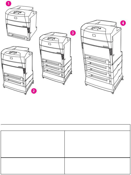
Model Configurations
This printer combines the quality and reliability of Hewlett-Packard printing with the features listed below. For more information on printer features, see the Hewlett-Packard website at http://www.hp.com/support/clj5500 or http://www.hp.com/support/clj5550.
The HP Color LaserJet 5500 series printer
1HP Color LaserJet 5500, 5500n, 5550, 5550n, 5500dn, and 5550dn printers
2HP Color LaserJet 5550dtn and 5550dtn printers
3HP Color LaserJet 5500dtn and 5550dtn printers
4HP Color LaserJet 5550hdn printer
Table 1-1. Model configurations
 HP LaserJet 5500 models
HP Color LaserJet 5500 printer (model number C9656A)
The HP CLJ 5500 printer is the base model, which includes 96 megabytes (MB) of synchronous dynamic random access memory (SDRAM), one 500-sheet input tray. This model comes with three optional EIO slots, standard bidirectional parallel port (IEEE-1284-C compliant), and a Fast InfraRed (FIR) port.
HP Color LaserJet 5500n printer (model number C7131A)
The HP CLJ 5500n printer contains all of the features of the base model plus an HP Jetdirect 615N print server (network card) and is only available in Europe.
2 Chapter 1 Printer description |
ENWW |

Table 1-1. Model configurations (continued)
HP Color LaserJet 5500dn printer (model number C9657A)
The HP CLJ 5500dn printer contains all of the features of the base model plus an HP Jetdirect 615N print server (network card), and automatic 2-sided printing (duplexing).
HP Color LaserJet 5500dtn printer (model number C9658A)
The HP CLJ 5500dtn printer contains all of the features of the base model plus an HP Jetdirect 615N print server (network card) and automatic 2- sided printing (duplexing), an additional 500sheet feeder, and 160 MB of SDRAM.
HP Color LaserJet 5500hdn printer (model number C9659A)
 HP LaserJet 5550 models
HP Color LaserJet 5550 printer (model number Q3713A)
HP Color LaserJet 5550n printer (model number Q3714A)
HP Color LaserJet 5550dn printer (model number Q3715A)
The HP CLJ 5500hdn printer contains all of the features of the base model with an HP Jetdirect 615N print server (network card) and automatic 2- sided printing (duplexing), two additional 500sheet feeders, a hard disk, and 160 MB of SDRAM.
The HP CLJ 5550 printer is the base model, which includes 128 megabytes (MB) of dual-data- rate (DDR) synchronous dynamic random access memory (SDRAM), plus 32 MB of additional memory on the formatter board for a total of 160 MB of memory, and a 500-sheet input tray.
The printer provides three enhanced input/output (EIO) slots, wireless connectivity, an auxiliary port, a universal serial bus (USB) connection, and a standard bidirectional parallel cable interface (IEEE-1284-C compliant).
The HP CLJ 5550n printer contains all of the features of the base model plus an HP Jetdirect 620N print server (network card).
The HP CLJ 5550dn printer contains all of the features of the base model plus an HP Jetdirect 620n print server (network card) and automatic 2- sided printing (duplexing).
HP Color LaserJet 5550dtn printer (model number Q3716A)
HP Color LaserJet 5550hdn printer (model number Q3717A)
The HP CLJ 5550dtn printer contains all of the features of the base model plus an HP Jetdirect 620N print server (network card), automatic 2- sided printing (duplexing), an additional 500sheet feeder.
This model has 256 MB of DDR SDRAM, plus 32 MB of additional memory on the formatter board for a total of 288 MB of memory.
The HP CLJ 5550hdn printer contains all of the features of the base model plus an HP Jetdirect 620N print server (network card), automatic 2- sided printing (duplexing), and three addtional 500-sheet feeders.
This model has 256 MB of DDR SDRAM, plus 32 MB of additional memory on the formatter board for a total of 288 MB of memory.
ENWW |
Model Configurations |
3 |

Performance, memory, and other printer features
This printer series combines the quality and reliability of Hewlett-Packard printers with the features listed in Table 1-2. Features.
Table 1-2. Features
Performance |
● |
HP Color LaserJet 5500 models: Up to 22 pages per minute |
|
|
(ppm) for A4-size paper and up to 21 ppm for letter size paper |
|
|
HP Color LaserJet 5550 models: Up to 28 pages per minute |
|
|
(ppm) on A4 size paper and up to 27 ppm for letter size paper |
|
● Also prints on transparencies and glossy paper |
|
Memory |
● |
HP Color LaserJet 5500, 5500n, 5500dn models contain 96MB of |
|
|
synchronous dynamic random access memory (SDRAM). |
|
|
Memory specification: All HP Color LaserJet 5550 series printers |
|
|
use 200-pin SODIMM that support 128 or 256MB of RAM |
|
● HP Color LaserJet 5500dtn and 5500hdn printer models contain |
|
|
|
160MB SDRAM. |
|
● HP Color LaserJet 5550, 5550n, 5550dn models contain 160MB |
|
|
|
DDR plus 32MB of additional memory on the formatter board and |
|
|
an additional open DIMM slot. |
|
|
HP Color LaserJet 5550dtn and 5550hdn models contain 288MB |
|
|
of SDRAM: 256MB DDR plus 32MB of additional memory on the |
|
|
formatter board and an additional DIMM slot. |
|
|
These printer models contain two 200-pin SODIMM slots that |
|
|
accept 128 or 256 MB RAM each |
|
● Optional hard drive can be added via an EIO slot (included with |
|
|
|
the HP Color LaserJet 5500hdn and 5550hdn models only). This |
|
|
is optional for all other printer models. |
User interface |
● |
Graphic display on control panel |
|
● Enhanced Help with animated graphics |
|
|
● Embedded Web server to access support and order supplies |
|
|
|
(network-connected printers) |
|
● HP Toolbox software provides printer status and alerts, configure |
|
|
|
printer settings, view documentation and troubleshooting |
|
|
information, and print internal printer information pages (for |
|
|
HP Color LaserJet 5550 models only). |
Supported printer |
● |
HP PCL 6 |
personalities |
● |
HP PCL 5c |
|
● |
PostScript 3 emulation |
|
● |
Automatic language switching |
|
● Direct PDF support (HP Color LaserJet 5550 models only) |
|
|
● XHTML support (HP Color LaserJet 5550 models only) |
|
Storage features |
● |
Job storage (for printers with a hard disk) |
|
● Personal identification number (PIN) printing (for printers with |
|
|
|
hard drives) |
|
● |
Fonts and forms |
Fonts |
● |
80 internal fonts available for both PCL and PostScript emulation |
|
● 80 printer-matching screen fonts in TrueType™ format available |
|
with the software solution
● Supports forms and fonts on the hard drive using HP Web Jetadmin.
4 Chapter 1 Printer description |
ENWW |

Table 1-2. Features (continued)
Paper handling |
● |
Prints on paper from 76 x 127 mm (3 x 5 inches) up to 306 x 470 |
|
|
mm (12.1 x 18.5 inches) |
|
● Prints on paper with weights from 60 g/m2 to 199 g/m2 (16 to 53 lb |
|
|
|
bond) |
|
● Prints on a wide range of media types including glossy, labels, |
|
|
|
overhead transparencies, and envelopes |
|
● |
Multiple gloss levels |
|
● A 500-sheet paper feeder (Tray 2) that supports paper sizes from |
|
|
|
148 x 210 mm (5.8 x 8.3 inches) up to 297 x 432 mm (11.6 x 17 |
|
|
inches). |
|
● Optional 500-sheet paper feeders (Trays 3, 4, and 5 (HP Color |
|
|
|
LaserJet 5550 models only) supports paper sizes from 148 x 210 |
|
|
mm (5.8 x 8.3 inches) up to 297 x 432 mm (11.6 x 17 inches). |
|
● Automatic two-sided printing on all HP Color LaserJet |
|
|
|
5500dn/5550dn, HP Color LaserJet 5500dtn/5550dtn, and |
|
|
HP Color LaserJet 5500hdn/5550hdn printers |
|
● 250-sheet face-down output bin. |
|
Accessories |
● |
Printer hard drive, which provides storage for fonts and macros as |
|
|
well as job storage; standard on HP Color LaserJet 5500hdn and |
|
|
5550hdn models only |
|
● Printer stand (recommended for additional optional trays) |
|
|
● Optional Tray 3 is standard on the HP Color LaserJet 5500dtn |
|
|
|
and HP Color LaserJet5550dtn models. Optional trays 3 and 4 |
|
|
are standard on the HP Color LaserJet 5500hdn models. Optional |
|
|
Trays 3, 4, and 5 are standard on the HP Color LaserJet 5550hdn |
|
|
models. All optional trays support support paper sizes from 148 x |
|
|
210 mm (5.8 x 8.3 inches) up to 297 x 432 mm (11.6 x 17 inches). |
|
● HP Color LaserJet 5500 models: Fast InfraRed (FIR) pod |
|
|
● HP Color LaserJet 5550 models: Two-200-pin DDR SDRAM slots. |
|
|
|
One slot is available for adding memory to the printer. DDR |
|
|
SDRAM memory is available in 128 and 256 MB modules |
|
● HP Color LaserJet 5500 supports four 168-pin dual inline memory |
|
|
|
(DIMM) slots and the fifth 100-pin DIMM slot. Memory can be |
|
|
expanded up to 416 MB, which is available in 64MB, 128MB, or |
|
|
256MB. |
Connectivity |
● |
Optional enhanced input/output (EIO) network card; comes |
|
|
standard on HP Color LaserJet 5500n/5550n, HP Color LaserJet |
|
|
5500dn/5550dn, HP Color LaserJet 5550dtn/5550dtn, |
|
|
andHP Color LaserJet 5500hdn/5550hdn printers |
|
● HP Color LaserJet 5550 models only: USB 1.1 connection |
|
|
● HP Web Jetadmin software |
|
|
● Standard bidirectional parallel cable interface (IEEE -1284-C |
|
|
|
compliant) |
|
● The HP Color LaserJet 5550 model printer supports an auxiliary |
|
|
|
connection for paper handling input devices. |
|
● HP Color LaserJet 5550 models only: Both USB and parallel |
|
|
|
connections are supported, but cannot be used at the same time |
|
● HP Color LaserJet 5500 model only: Infrared (FIR) connection. |
|
Supplies |
● |
Supplies status page contains information on toner level, page |
|
|
count, and estimated pages remaining |
|
● No-shake cartridge design |
|
|
● Printer checks for authentic HP print cartridges at cartridge |
|
|
|
installation |
● Internet-enabled supply-ordering capabilities (using embedded Web server, printer Status and Alerts, or Toolbox (HP Color LaserJet 5550 models only)
ENWW |
Performance, memory, and other printer features |
5 |
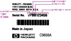
Identification
Model and serial numbers
The model number and serial numbers are listed on identification labels located on the rear of the printer. The model number is alphanumeric, such as C9656A for the HP Color LaserJet 5550. The serial number contains information about the country/region of origin, the printer version, production code, and the production number of the printer.
Figure 1-1. Model and serial number information
Power and regulatory information
The identification labels on the rear of the printer also contain power rating and regulatory information as shown in Figure 1-2. Sample label.
6 Chapter 1 Printer description |
ENWW |
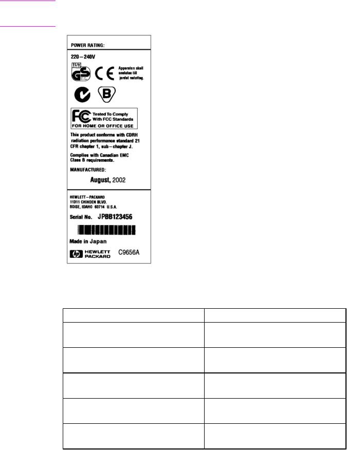
CAUTION
Figure 1-2.
Converting the voltage on the printer can damage the printer. Do not use any voltage other than the operating voltage. Any attempt to convert operating voltages will void the product warranty (for example, attempting to change a 110V printer to a 220V printer).
Sample label
Table 1-3. Model names and numbers
Model name |
Model number |
HP Color LaserJet 5500 |
C9656A |
HP Color LaserJet 5550 |
Q3713A |
HP Color LaserJet 5500n |
C7131A |
HP Color LaserJet 5550n |
Q3714A |
HP Color LaserJet 5500dn |
C9657A |
HP Color LaserJet 5550dn |
Q3715A |
HP Color LaserJet 5500dtn |
C9658A |
HP Color LaserJet 5550dtn |
Q3716A |
HP Color LaserJet 5500hdn |
C9659A |
HP Color LaserJet 5550hdn |
Q3717A |
ENWW |
Identification 7 |
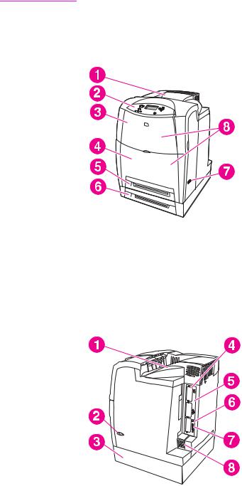
Note |
This manual describes the HP Color LaserJet 5500 series printer which includes the |
|
HP Color LaserJet 5500 models and the HP Color LaserJet 5550 models. |
|
HP Color LaserJet 5500 models |
Figure 1-3. Front view, HP Color LaserJet 5500 models
1Output bin
2Printer control panel
3Top cover
4Front cover (includes tray 1)
5Tray 2 (500-sheet standard tray)
6Tray 3 (500-sheet paper feeder; optional)
7On/off switch
8Access to print cartridges, transfer unit, and fuser
Figure 1-4. Back view, HP Color LaserJet 5500 models
1Output bin
2On/off switch
3Tray 3 500-sheet paper feeder (optional)
4EIO connections (3 total)
5Memory access
6Fast InfraRed (FIR) connection
7Parallel connection
8Power connection
8 Chapter 1 Printer description |
ENWW |
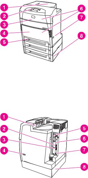
HP Color LaserJet 5550 models
Figure 1-5. Front view, HP Color LaserJet 5550 models
1Output bin
2Printer control panel
3Top cover
4Front cover includes Tray 1
5Tray 2 (500 sheet standard tray)
6Access to print cartridges, transfer unit, and fuser
7On/off switch
8Tray 3, Tray 4, and Tray 5 (optional)
Figure 1-6. Back view, HP Color LaserJet 5550 models
1Output bin
2Auxiliary connector
3Parallel connection
4On/off switch
5EIO connections (3 total)
6Memory access
71.1 USB connection
8Tray 3, Tray 4, or Tray 5 (optional)
ENWW |
Identification 9 |
Loading...