

Hellwig 7587 User Manual
INSTALLATION INSTRUCTIONS
REAR STABILIZER BAR
Thank you for purchasing a quality Hellwig Product.
MOUNTING LOCATION:
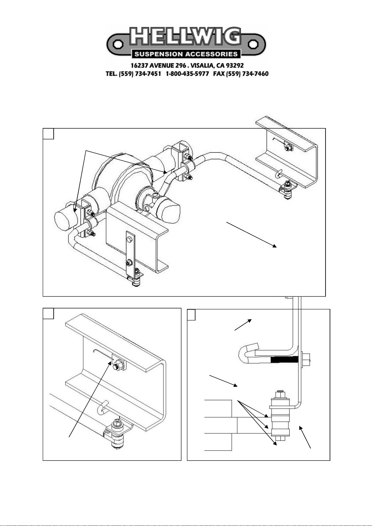
1
SADDLE BRACKETS, D-BUSHINGS,U-PLATES, U-BOLTS
& MOUNTING HARDWARE ON SWAY BAR & AXLE
F
R
O
N
T
O
F
V
E
H
I
C
L
E
2
THREADED PLATE
WITH WELDED
PIGTAIL
3
VEHCILES FRAME
J-BOLT
END LINK ASSY
WASHER, BUSHING,
LOCK NUT, BOLT
FRAME BRACKET
7587 ( R-369 ) 03/06/07

TORQUE TABLE
BOLT SIZE: 3/8” = 20-30 ft. lbs. – 7/16” = 35-45 ft. lbs. – ½” = 50-70 ft. lbs. – 9/16” = 70-90 ft. lbs.
SAFETY: BEFORE STARTING YOUR INSTALLATION, BE SURE TO SET PARKING BRAKE AND CHOCK
TIRES.
NOTE: TO EASE INSTALLATION AND TO PROPERLY ADJUST BAR, THE WEIGHT OF THE VEHICLE
MUST BE ON THE SUSPENSION, AS IF DRIVING DOWN THE ROAD.
DO NOT RAISE VEHICLE BY FRAME.
1. Place the U-bolts on the axle pointing down. Be careful as not to damage the brake line mounted on
the axle. Install the D-shaped poly bushings on the flat areas of the sway bar between the center
hump and the arms of the sway bar. Attach the saddle brackets to the U-bolts an the axle. Raise the
sway bar to the axle, align the D-bushings to match the U-bolts on the axle. Position the U-plates
over the D-bushing and attach with the 1/2” hex nuts supplied. Leave loose at this time to allow for
adjustment later. (SEE PHOTO (1) FOR ASSEMBLY).
2. On the vehicles frame locate the pre-drilled holes. Attach the angle frame brackets to the frame with
the mounting hardware provided. On the inside of the frame the threaded plate with attached wire
(pigtail) will be used. ( Note on some applications a hex nut can be used ). Be careful as to not damage or crimp any electrical wires or brake lines that run thru the frame rail. Locate the J-bolts, with
the hooked end hook the bottom lip of the vehicles frame insert threaded end thru the hole on the
angle frame bracket. Attach with mounting hardware provided. Leave loose at this time to allow
for adjustment later. ( SEE PHOTOS (2&3). Do the same on opposite frame.
3. Attach the end link assemblies to the sway bar. End link bolt, flat washer, round poly-bushing, insert
thru hole of arm on the sway bar, bushing, flat washer, bushing. Raise the sway bar up to the angle
frame brackets. Insert end link assembly thru hole on frame bracket, install bushing, flat washer and
lock nut. Do the same on opposite end. Leave loose to allow for adjustment later. ( SEE PHOTO
(3).
4. With the sway bar centered at theaxle and the end link assemblies straight up and down as possible
torque all mounting hardware to specified rates.
5. Bounce the vehicle, checking for clearance on all undercarriage components, exhaust, shocks, brake
and fuel lines. Test drive the vehicle, re-check your installation re-adjust and torque as required. Recheck your installation on a monthly regular basis thereafter.
ATTENTION INSTALLER: BE SURE THAT THECUSTOMER RECEIVES THIS INSTRUCTION
SHEET, ALL IMORTANT NOTE CARDS AND THE WARRANTYFORM
7587 ( R-369 ) 03/06/07
 Loading...