

Hellwig 55904 User Manual
1
559-734-7451 800-367-5480 FAX 559-734-7460
INSTALLA TION INSTRUCTIONS
FRONT STABILIZER BAR
1970-72 B-Body Mopar; 1970-74 E-Body Mopar
Thank you for purchasing a quality Hellwig Product.
PLEASE READ THIS INSTRUCTION SHEET COMPLETELY BEFORE STARTING YOUR INSTALLATION
TORQUE TABLE
BOLT SIZE: 3/8” = 20 -30 ft. lbs. – 7/16” = 35-45 ft. lbs. – ½” = 50-70 ft. lbs. – 9/16” = 70-90 ft. lbs.
SAFETY: BEFORE STARTING YOUR INSTALLATION, BE SURE TO SET PARKING BRAKE AND
CHOCK TIRES.
NOTE: TO EASE INSTALLATION AND TO PROPERLY ADJUST THE SWAY BAR, THE WEIGHT
OF THE VEHICLE MUST BE ON THE SUSPENSION AS IF DRIVING DOWN THE ROAD.
DO NOT RAISE THE VEHICLE BY THE FRAME.
NOTE: THIS UNIT IS DESIGNED AS A REPLACEMENT FOR THE FACTORY INSTALLED FRONT
ANTI-SWAY BAR OR AS AN ADDITION IF NOT EQUIPPED.
NOTE: THIS KIT INCLUDES LOCK NUTS WHICH REQUIRE TIGHTENING WITH A WRENCH
AFTER BEING STARTED BY HAND.
5904 ( R-5904 ) 04/17/2007
559-734-7451 800-367-5480 FAX 559-734-7460
2
3
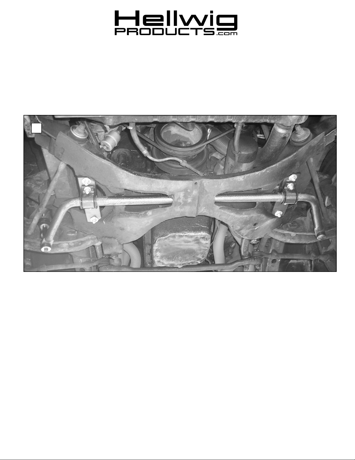
1. If equipped, remove the factory installed anti sway bar and the mounting hardware.
2. Insert bar through hole in K-member as shown in photo 1.
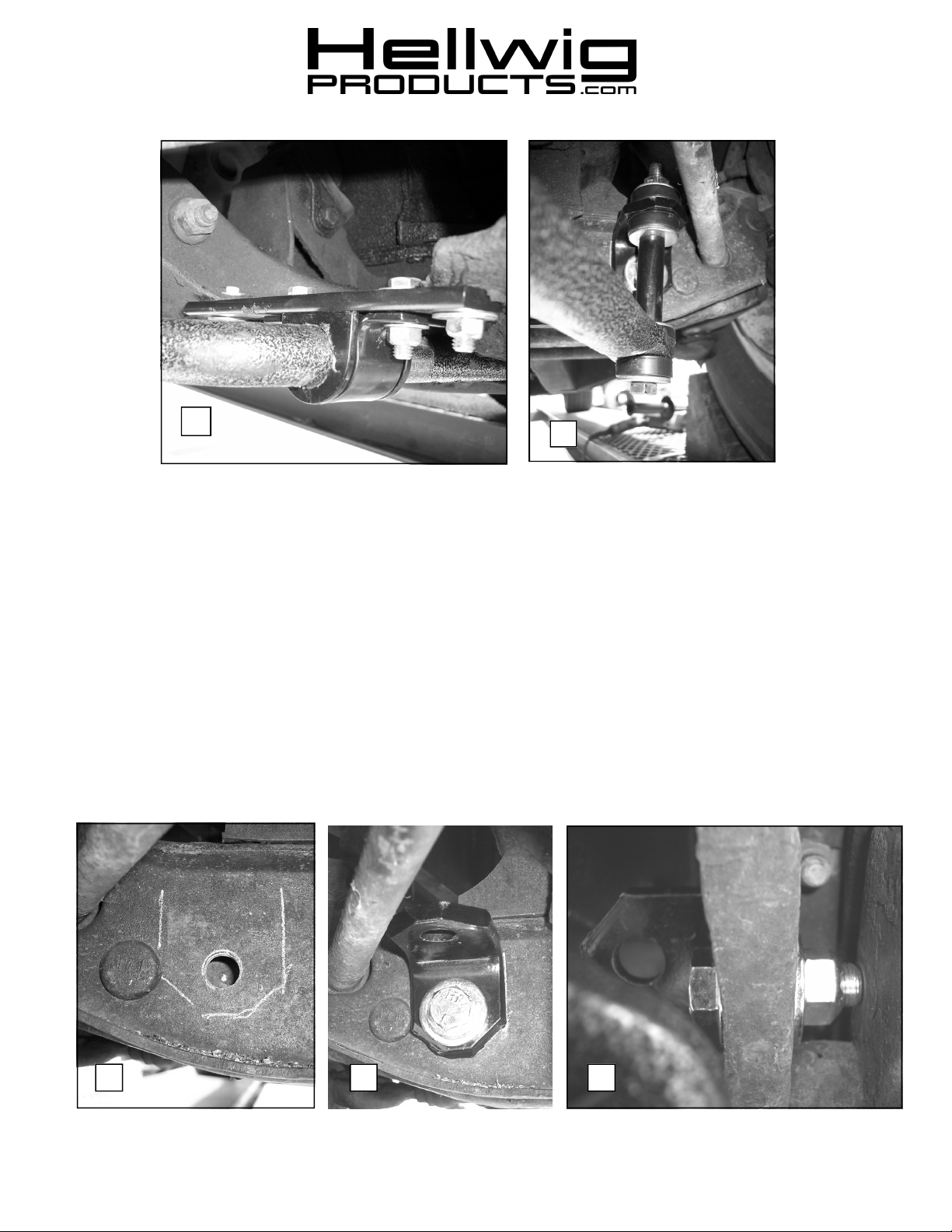
3. Attach mounting plates to K-member as shown in photos 1 & 2 using 3/8-16 X 1-1/4” bolts, large
washers and locknuts. Tor que to 25 ft-lb.
4. Lubricate polyurethane D-bushings and insta ll on sway bar in the location where they will attach to
the mounting plates. Place u-plates over D-bushings and attach to mounting plates with 3/8-16 X11/4” bolts, small washers and locknuts. Leave loose for adjustment later.
5. If not equipped with factory sway bar mounts, assemble end links and angle brackets as shown in
photo 3. If equipped with factory sway bar mounts, skip to line 8.
6. Align end links for best alignment and mark location of bracket as shown in photo 4. Drill a
17/32” (.531) hole in front face of control arm only. Do not drill through rear face of control
arm. See photos 4,5&6.
7. Attach angle bracket to control arm using 1/2” bolt, washers, and locknut as shown in photos 5&6.
Align bracket and torque bolt to 50-60 ft-lb. See photos 5&6.
4 5
6
5904 ( R-5904 ) 04/17/2007
 Loading...