


User Manual
H3Dll

C O N T E N T S
Introduction |
4 |
|
|
1General overview of body and viewfinder —
control and display |
8 |
|
|
Grip display |
10 |
View f inder display |
12 |
Audio feedback |
16 |
2 Camera Body |
18 |
|
|
Carr ying strap |
19 |
Rechargeable bat ter y |
19 |
Bat ter y charger |
19 |
Charging the bat ter y |
20 |
Rechargeable bat ter y grip − general |
20 |
Rechargeable bat ter y grip − precautions |
21 |
Reser ve lithium-bat ter y grip |
21 |
Bat ter y life |
21 |
Bat ter y status (r e c h a r g e a b l e b a t t e r y o n l y) |
22 |
View f inder screen |
22 |
Accessor y connec tion |
23 |
PCconnec tor |
23 |
Base plate |
23 |
3 Viewfinder |
24 |
|
|
Par ts & Components |
25 |
At taching and removing the view f inder |
25 |
Eyepiece adjustment |
25 |
Eye cup |
25 |
Integral f lash unit |
25 |
4 Lenses |
26 |
|
|
Par ts & Components |
27 |
At taching a lens |
27 |
Removing a lens |
27 |
Lens cap |
27 |
Filter s |
27 |
Lens shades |
27 |
Shut ter and aper ture control |
27 |
Depth- of-f ield calculation |
28 |
Depth- of-f ield / visual preview |
28 |
Infrared focus set tings |
28 |
Focus aid |
28 |
CF adapter |
29 |
Specif ic-lens information |
29 |
5 General overview of digital |
|
capture unit |
30 |
|
|
The control panel |
32 |
Over view of menu system and navigation |
34 |
Over view of menu struc ture |
35 |
6 Initial General Settings and |
|
Preparation |
36 |
|
|
Set ting the menu language |
36 |
Storage and shooting |
37 |
Image storage modes / shooting |
37 |
Selec ting the current medium |
37 |
Using compac t f lash memor y cards |
38 |
Working with an ImageBank-II |
39 |
Tethered to a computer |
40 |
7 Storage working with media |
|
and batches |
41 |
Organizing work with batches |
41 |
Navigating media and batches |
41 |
Creating new batches |
43 |
Using Instant Approval Architec ture |
4 4 |
Reading and changing approval status |
45 |
Browsing by approval status |
46 |
Deleting by approval status |
46 |
8 Overview of viewing, deleting
and copying images |
47 |
|
|
Basic image browsing |
47 |
Choosing the current batch |
47 |
Browsing by approval status |
47 |
Zooming in and out |
47 |
Zooming in for more detail |
48 |
Thumbnail views |
48 |
Preview modes |
49 |
Histogram mode |
50 |
Fulldetails mode |
51 |
Bat ter y-saver mode |
51 |
Full-screen mode |
51 |
Overexposure indicator |
51 |
Not all the images in this manual were taken with a Hasselblad H3D II. They are used for illustrative purposes only and are not intended to represent the image quality produced by a Hasselblad H3D II. © Jens Karlsson/Hasselblad , David Jeffery and Mats Bengtsson

|
|
|
Deleting images |
52 |
|
Single Shot |
88 |
|
|
|
Transferring images |
52 |
|
Continuous |
89 |
|
|
|
|
|
|
Autofocus mode |
89 |
|
|
|
|
|
|
Prof iles |
90 |
|
|
9 |
MENU—ISO, White balance, |
|
|
Using prof iles |
91 |
|
|
|
Media, Browse |
53 |
|
Making a prof ile |
90 |
|
|
|
Menu system over view |
53 |
|
Changing a prof ile name |
91 |
|
|
|
Navigating the menu system |
53 |
|
|
|
|
|
|
Menu struc ture |
54 |
|
14 Advanced Features |
92 |
|
|
|
Items on the main menu |
54 |
|
General over view of camera menu |
93 |
|
|
|
Language |
55 |
|
Self Timer |
94 |
|
|
|
Set tings check |
55 |
|
Bracketing |
96 |
|
|
|
ISO |
56 |
|
Inter val |
98 |
|
|
|
White balance |
56 |
|
Set tings |
99 |
|
|
|
Media |
58 |
|
Custom Options |
99 |
|
|
|
Browse |
59 |
|
Image Info |
104 |
|
|
|
|
|
|
Tex t set ting |
104 |
|
|
10 |
MENU—Storage |
60 |
|
Date & Time |
105 |
|
|
|
Delete |
61 |
|
System status |
106 |
|
|
|
Format |
65 |
|
Drive |
107 |
|
|
|
Copy |
66 |
|
|
|
|
|
|
Batch |
68 |
|
15 Flash |
108 |
|
|
|
|
|
|
|
|
|
|
|
Default Approval Level |
69 |
|
Flash measure |
111 |
|
|
11 |
MENU—Settings |
70 |
|
16 Multi Shot |
112 |
|
|
|
|
|
|
|
|
|
|
|
User Inter face |
71 |
|
|
|
|
|
|
Camera |
72 |
|
17 Optional Accessories |
113 |
|
|
|
About |
77 |
|
|
|
|
|
|
Default |
77 |
|
18 Appendix |
117 |
|
|
|
|
|
|
|
|
|
|
|
Custom Options |
78 |
|
Glossar y |
118 |
|
|
|
|
|
|
Technical specif ications |
122 |
|
|
12 |
Light Metering & |
|
|
Care, digital capture unit |
125 |
|
|
|
Exposure Control |
79 |
|
Equipment care and ser vice |
127 |
|
|
|
Metering method |
80 |
|
|
|
|
|
|
Exposure method |
81 |
|
|
|
|
|
|
Manual exposure mode |
81 |
|
|
|
|
|
|
Automatic exposure mode |
82 |
|
|
|
|
|
|
ISO / WB |
83 |
|
|
|
|
|
|
AE-L but ton |
84 |
|
|
|
|
|
|
Exposure compensation/Quick Adjust |
85 |
|
|
|
|
|
13 |
General Functions |
86 |
|
|
|
|
|
|
Power− ON |
87 |
|
|
|
|
|
|
Power−Standby |
87 |
|
|
|
|
|
|
Power− OFF |
87 |
|
|
|
|
|
|
Manual focus |
87 |
|
|
|
|
|
|
Manual focus mode |
88 |
|
|
|
|
|
|
Autofocus override in manual mode |
88 |
|
|
|
|
|
|
Autofocus |
88 |
|
|
|
|
|
|
|
|
|
|
|
3
Welcome to Hasselblad !
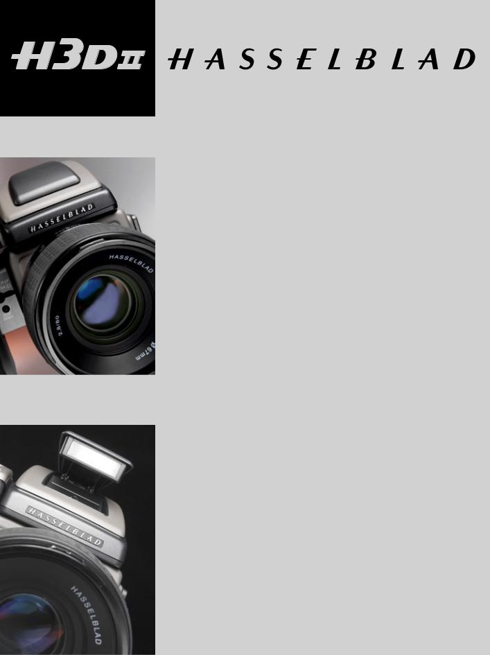
The H3D II represents the forefront of medium format photography. This unrivalled position is based on an accumulation of experience spanning more than fifty years. By using Hasselblad equipment you share the decision made by of some of the world’s best and most famous photographers. Congratulations on a wise choice!
The H3D II is a development of the world’s first full-frame, large-sensor, medi- um-format DSLR camera. The H3D II has been developed around a brand new digital camera engine producing increased lens performance and a new level of image sharpness. By focusing solely on digital camera architecture, Hasselblad is able to offer photographers the full benefits of professional medium-format digital cameras as well as the ease of use of the best 35mm DSLRs.
The H3D II delivers outstanding performance, taking full advantage of the virtues of medium format photography. The result is flexibility for the professional photographer, including the freedom to choose between eye-level and waist-level viewfinders, digitally APO corrected lenses, and on-the-fly clas sification of images. Hasselblad’s Natural Color Solution delivers out-of-the-box image quality only achievable in a true digital camera system.
Medium Format digital capture advantage
In digital photography, the advantages of large format cameras have become even more obvious. The 6×4.5 cm window allows the H3D II to use the largest image sensors currently available in digital photography – up to more than twice the physical size of a 35mm camera sensor. Consequently the sensor holds more and larger pixels, which deliver the highest possible image quality in terms of moiré-free color rendering without gradation break-ups in even the finest lit surfaces.
An impressive lens line
The highly renowned HC/HCD lens line includes 10 Auto-Focus lenses, all with central shutters. Range is from 28mm to 300mm, 50-110mm zoom, 35-90mm zoom and 1.7X converter. The HTS 1.5 tilt/shift adapter delivers an easy to use, portable tilt/shift solution for 5 HC/HCD lenses ranging from 28mm to 100mm. The CF adapter allows use of the classic CF-lenses from the Hasselblad V-camera, with full use of their central shutters, allowing flash to be employed at
4

shutter speeds up to 1/800s. The central shutter also improves image quality by reducing camera vibration. And thanks to the large format of the H System cameras, there is a considerably shallower depth of field range, making it much easier to utilize selective focus to creative effect.
A choice of large and bright viewfinders
One of the important traditional advantages of the medium format is the extra-large and bright viewfinder image, enabling extremely precise compositions and easy operation in dim lighting. The H3D II comes with the HVD 90x viewfinder designed for full performance over the large 36x48mm sensor. Hasselblad has added an interchangeable waist-level viewfinder, the HVM, for the entire range of H system cameras. The bright and large viewfinder image is ideal for creative composing and the photographer is able to shoot in the fashion that suits them most; maintaining eye contact with the model, or gaining impact by shooting from a point lower than eye-level, for example.
Phocus software for the professional
Phocus provides an advanced software toolbox that has been especially designed to achieve optimum workflow and absolute image perfection from Hasselblad raw image files. With the H3D II camera system Phocus provides:
• UncompromisingImageQuality
• SpecialextendedcameracontrolswithwhichtooperateyourH3D
II camera. These features, such as live video for easier shot set-up and workflow, or the ability to control the lens drive for focusing when the camera is in a remote position or when the digital capture unit is mounted on a view camera, bring an entirely new level of flexibility to the way you shoot.
• MoiréRemovalTechnologyautomaticallyapplieddirectlyonthe raw data, leaving image quality intact and eliminating the need to carry out special masking selections or other manual procedures, saving hours of tedious post-production work.
• FlexibleWorkflow.ThePhocusGUIfeatureseasy-to-useoptions that allow you to customize your set-up to suit a range of different workflow situations, such as choice of import source, browsing/comparison functions, file management, image export in a number of file formats, pre-setting of options for upcoming shoots, and much, much more.
• NewMetadata(GPS,etc).Theextendedmetadataincludedinall
Phocus images provides for accurate and detailed cataloguing and
indexing,easyimagemanagement,andincludesaddedGPSdata functionality in order to allow a range of new functions. Phocus linksGPSdatadirectlytoGoogleEarth,forexample,makinggeographic reference a snap and image storage and retrieval much easier.
• PerfectViewingQuality.ThePhocusViewerdeliversimageviewing quality that matches every detail of what you will see later in Photoshop. In addition, the Phocus Viewer allows you to customize layout and composition to suit your current or desired workflow, providing a wide range of options including full view, compare, browse, horizontal, or vertical view, and so on. You can have multiple folders open simultaneously for side-by-side viewing, comparison, and selection.
Ultra-Focus and Digital Auto Correction for image perfection
The H3D II camera allows information from the lens and exact capture conditions to be fed to the camera processor for ultra-fine-tuning of the auto-focus mechanism, taking into account the design specifications of the lens and the optical specifications of the sensor. In this waythefullHClensprogramisevenfurtherenhanced,bringinganew level of sharpness and resolution. Digital correction for color aberration, distortion and vignetting is also added. “Digital Auto Correction”
(DAC), is an APO-chromatic correction of the images based on a combination of the various parameters concerning each specific lens for each specific shot, ensuring that each image represents the best that your equipment can produce. Based upon these techniques, Hasselblad has been able to expand our lens program with a 35–90 mm zoom lens that has been especially developed for the H3D product family. The design of this lens has been optimized for the actual 36x48mm area of the sensor to make it more compact and to work in conjunction with DAC. This is a critical part of the technology behind capturing perfect images with this extraordinary lens. The result is clear: DAC increases image resolution and delivers perfect pixels, thereby providing an ideal basis for optimal image rendering.
Hasselblad’s unique natural colors
Hasselblad’sNaturalColorSolution(HNCS)enablesyoutoproduce outstanding and reliable out-of-the-box colors, with skin tones, specific product colors and other difficult tones reproduced easily and effectively. In order to incorporate our new unique HNCS and DACfeatures we have developed a custom Hasselblad raw file format called3FRAW(3FR).Thisfileformatincludeslosslessimagecompression, which reduces the required storage space by 33%. The 3FR filescanbeconvertedintoAdobe’srawimageformatDNG(‘Digital Negative’),bringingthisnewtechnologystandardtotheprofessional
5

photographer for the first time. In order to utilize DAC and optimize the colors of the DNG file format, conversion from 3FR must take place through Phocus.
and easy way to classify and select images, in the field or back at the studio. IAA is a Hasselblad trademark and Hasselblad has a patent pendingontheinvention.Extralarge3”displayontheH3DIIprovides a realistic, high quality and perfect contrast image view, even in bright sunlight.
GPS Recording Flexibility
Hasselblad’sGlobalImageLocator(GIL)isanaccessoryforusewith anyHasselbladH-Systemdigitalcaptureproduct.WiththeGILde- vice,allimagescapturedoutsidearetaggedwithGPScoordinates, time and altittude. This data provides the key to a number of future applications involving image archiving and retrieval. One example is thedirectmappingofimagesinPhocussoftwaretotheGoogleEarth application.
Instant Approval Architecture
BuildingonthesuccessofitsAudioExposureFeedbacktechnology, HasselbladhascreatedInstantApprovalArchitecture(IAA),anenhanced set of feedback tools, designed to enable the photographer to focus o n the shoot rather than the selection process. IAA triggers audible and visual signals for each image captured, notifying the photographer immediately of its classification status. The information is recorded both in the file and in the file name, providing a quick
Three modes of operation and storage
The H3D II offers a choice of storage devices: portable CF cards, the flexible ImageBank-II or a computer hard drive. With these three operating and storage options, you are able to select a mode to suit the nature of the work in hand, whether in the studio or on location.
Options for working with tilt/shift
Two basic options are available for tilt/shift work with H3D II. A simple, portable adapter solution and the classic view camera solution. The HTS tilt/shift adapter for H3D II allows for portable tilt/shiftwith theHC/HCDlensrangefrom28mmto100mm(pleaserefertothe separatedatasheetonthisproductfordetails).
To further increase usability, the H3D II has been designed to allow the digital capture unit to be detached and used on a view camera by way of an adapter (please refer to the separate datasheet on HasselbladViewCamerasolutionsfordetails).
The primary goal of all camera development is of course the seamless and unobtrusive production of superb images, regardless of situation. Hasselblad cameras have abilities and features that you may not think you need yet; each individual has their own way of working. But the H3D II has tremendous scope for fine-tuning your technique possibly beyond your present ambitions.
Takeyourtimetolearntheintricaciesandpotentialsofyournewcamera.Goatyour own pace and explore the possibilities when you feel ready for the next step. Results will be good from the word go, that’s guaranteed, but when you want to make improvements or work more efficiently perhaps, the capabilities are there for you.
The supreme Hasselblad potential is there, it’s up to you to exploit it!
6
Computer system requirements
Digital files naturally end up on a computer for processing. Image-storage and correction requires a certain minimum standard regarding computer capabilities. Large images will require a high-performance computer with plenty of memory, advanced graphics capabilities and a recent operating system. In most cases, the computer should include a FireWire 800/400 connector, which will enable you to load images directly from the camera or ImageBank-II (see note below). To load images stored on the removable compact-flash card, you could instead use a compact-flash card reader, but FireWire is recommended for maximum flexibility.
Warnings and restrictions
■IfyouwanttopowertheH3DIIfromaPClaptop(asopposedtoaMacintoshlaptop), you must ensure that the FireWire port on the computer is capable of supplying power. Please note the following:
•MostrecentMacintoshcomputersarecompatible,bothdesktopsandlaptops.
•MostrecentdesktopPCcomputersarecompatible.
•Most laptop PC computers are NOT compatible (but can be modified in many cases).
■Keep the H3D II and all other computer equipment away from moisture wherever possible. If your camera becomes wet, disconnect from power and allow it to dry before attempting to operate again.
■Always take great care when you remove the digital capture unit for cleaning —the exposed CCD sensor protective filter is vulnerable to damage.
■Keep all cables connected to or from your camera and computer out of the way where they will not be tripped over.
■Ensuretheventilationopeningsremainuncoverdonthedigitalcaptureunitwhenitis active.
■Your new Hasselblad camera may have been supplied in kit form or as separate items. There are a number of possible combinations depending on factors such as offers, bundles etc. Please ensure that all the items noted on the accompanying packing information have been supplied and are correct.
■Contact your Hasselblad dealer or distributor immediately if anything is missing or seems faulty in any way, quoting the serial numbers and purchase details where appropriate.
■Please keep purchase details and the warranty in a safe place.
■Familiarise yourself with the various parts and components. Leave protective covers on as much as possible and avoid touching glass surfaces and inserting fingers into the camera body. Hasselblad equipmentthas a robust construction and is capable of withstanding fairly rough treatment but nevertheless is a precision instrument and will serve you longer if treated with respect from the beginning.
■Finally, please check occasionally on the Hasselblad website–www.hasselblad.com– for any updates regarding user instructions, changes, news, or other information. If you have no Internet access, please contact your Hasselblad dealer or distributor for the latest information.
7

1
General overview of body and viewfinder
– control and display
LCD display on camera
LED display in viewfinder
Upgradeable firmware
Rapidly accessible menu
Interactive display
Customizable functions
All functions and settings on the H3D II camera body are accessed and altered by the control buttons and wheels on and around the grip aided visually by the display user-interface.
The information on the grip display has a great deal in common with display menus found in mobile/cell phones, etc. It is pixel based and therefore has a greater capa city to produce user-friendly symbols for rapid and secure interpretation.
8
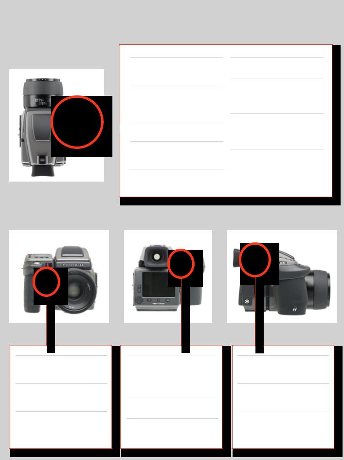
Below is an overview of the primary functions of the control wheels and buttons. Some controls have dual or triple functions according to the state of the menu or setting. A full description can be found further on in this manual.
Shutter release button
Releases shutter. Also activates camera from standby mode.
FLASH / (CONTROL LOCK) button
Locks settings to avoid inadvertent change. Also accesses flash settings as well as acting as Exit button.
AF button
 Accesses focus modes.
ISO/WB button
Accesses ISO and White Balance settings. Also acts as Save button.
Front control wheel
Accesses and changes various settings.
MENU button
Accesses menu.
Illumination/Battery status button
Illuminates grip display. Acesses battery status and general information screen.
ON.OFF (PROFILES/ESC) button
Turns the camera on and off. Accesses Profiles and acts as escape button for other functions.
Rear control wheel
Accesses and changes various settings.
M.UP button
Raises and lowers mirror. Can be reassigned to another function.
Remote release cord port
For attaching a remote release cord
(electrical).
STOP DOWN button
Stops down aperture to current setting. Can be reassigned to another function.
AE-L button
Locks light reading made in both automatic and manual exposure modes. Can be reassigned to another function.
 Format button
Re-formats CF card.
USER button
User assignable-function button.
Eyesight correction adjustment wheel
Personal eyesight adjustment facility.
EV correction adjustment button
Produces EV exposure compensation.
EXP button
Accesses exposure mode and metering method.
9
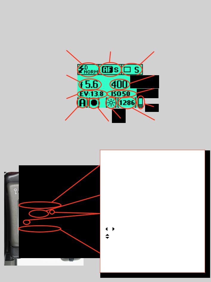
Grip display
Typical camera grip display. (Theinformation inbracketsdescribesthisparticularexampleonly).
|
Flash condition indication |
|
|
|
|
|
|
Focus setting |
|
|
|
|
|
|
|
|
|
|
|
|
Drive condition |
|
||||||||
|
(No exposure compensation, |
|
|
|
|
|
|
(Autofocus setting, single |
|
|
|
|
|
(Single setting) |
|
|||||||||||||||
|
normal flash synchronisation) |
|
|
|
|
|
|
shot mode) |
|
|
|
|
|
|
|
|
|
|
|
|
|
|
|
|
|
|
||||
|
|
|
|
|
|
|
|
|
|
|
|
|
|
|
|
|
|
|
|
|
|
|
|
|
|
|||||
|
|
|
|
|
|
|
|
|
|
|
|
|
|
|
|
|
|
|
|
|
|
|
|
|
|
|
|
|
|
|
|
|
|
|
|
|
|
|
|
|
|
|
|
|
|
|
|
|
|
|
|
|
|
|
|
|
|
|
|
|
|
|
|
|
|
|
|
|
|
|
|
|
|
|
|
|
|
|
|
|
|
|
|
|
|
|
|
|
|
Shutter speed setting |
|
|
|
Aperture setting |
|
|
|
|
|
|
|
|
|
|
|
|
|
|
|
|
|
|
|
|
|
|
|
|
|
|
(1/400s) |
|
|
|
(f/5.6) |
|
|
|
|
|
|
|
|
|
|
|
|
|
|
|
|
|
|
|
|
|
|
|
|
|
|
|
|
|
|
|
|
|
|
|
|
|
|
|
|
|
|
|
|
|
|
|
|
|
|
|
|
|
|
|
|
|
|
|
|
|
|
|
|
|
|
|
|
|
|
|
|
|
|
|
|
|
|
|
|
|
|
|
|
|
|
|
|
|
|
|
|
|
|
|
|
|
|
|
|
|
|
|
|
|
|
|
|
|
|
|
|
|
|
|
|
|
|
ISO setting |
|
||
|
|
|
|
|
|
|
|
|
|
|
|
|
|
|
|
|
|
|
|
|
|
|
|
|
|
|
(50 ISO/ASA) |
|
||
|
|
|
|
|
|
|
|
|
|
|
|
|
|
|
|
|
|
|
|
|
|
|
|
|||||||
|
Exposure Value display |
|
|
|
|
|
|
|
|
|
|
|
|
|
|
|
|
|
|
|
|
|
|
|
|
|
|
|
|
|
|
|
|
|
|
|
|
|
|
|
|
|
|
|
|
|
|
|
|
|
|
|
|
|
|
|
|
|
|
|
|
|
(EV 9.3) |
|
|
|
|
|
|
|
|
|
|
|
|
|
|
|
|
|
|
|
|
|
|
|
|
|
|
|
||
|
|
|
|
|
|
|
|
|
|
|
|
|
|
|
|
|
|
|
|
|
|
|
|
|
|
Low battery symbol |
|
|||
|
|
|
|
|
|
|
|
|
|
|
|
|
|
|
|
|
|
|
|
|
|
|
|
|
|
|||||
|
|
|
|
|
|
|
|
|
|
|
|
|
|
|
|
|
|
|
|
|
|
|
|
|
|
|
|
|
|
|
|
|
|
|
|
|
|
|
|
|
|
|
|
|
|
|
|
|
|
|
|
|
|
|
|
|
|
|
|
|
|
|
|
|
|
|
|
|
|
|
|
|
|
|
|
|
|
|
|
|
|
|
|
|
|
|
|
|
|
|
|
|
|
|
|
|
|
|
|
|
|
|
|
|
|
|
|
|
|
|
|
||||||||||||
|
Exposure mode indication |
|
|
|
|
Metering |
method |
|
|
|
White |
balance |
|
|
|
|
|
‘Capture counter’ |
|
|||||||||||
|
|
|
|
|
|
|
|
|
|
|
|
|
|
|||||||||||||||||
|
(Aperture priority setting) |
|
|
|
|
indication |
|
|
|
|
|
|
|
|
|
|
|
|
|
|
|
|
|
|
(1286 shots remaining on |
|
||||
|
|
|
|
|
(Centre weighted) |
|
|
(Daylight) |
|
|
|
chosen storage medium) |
|
|||||||||||||||||
|
|
|
|
|
|
|
|
|
|
|
|
|
|
|
|
|
|
|
|
|
|
|
|
|
|
|
|
|
|
|
|
|
|
|
|
|
|
|
|
|
|
|
|
|
|
|
|
|
|
|
|
|
|
|
|
|
|
|
|
|
|
Typical camera grip display when changing settings.
Command indication
The upper row on the screens describes commands (which changeaccordingtothesetting).Thebuttonimmediatelyabove each command effects the change. So in this case, for example,youwouldpresstheFLASHbuttonto‘exit’fromthescreen.
See note below.
Settings symbols
Symbolize the options available when settings are changed. The active symbol is depicted by a drop shadow.
Control wheel description and direction
Arrowheads symbolize which control wheel should be used to change the setting they are beside. In this case, the Bracketing option is chosen by the front control wheel and the number of captures in that option is chosen by the rear control wheel.
. . . |
= |
front control wheel |
|
= |
rear control wheel |
Setting information
The lower row on the screen displays information about the current state of the setting. In short, the upper row displays what you can do, and the lower row displays the current state of settings or what you have done.
10
The basic principle behind making changes is that the appropriate button is first pressed to access the menu and then settings altered by way of the control wheels. The appropriate control wheel is designated by arrowheads alongside the setting description.
Some buttons have a toggle function, the ON.OFF button has a quick ‘click’ action as well as a longer (half-second) ‘press’ action and the shutter release has two positions: ‘half-press’ and ‘full-press’.
Several buttons on the grip are multifunctional, according to the state of the menu. In the example illustrated here, the FLASH button functions as the EXIT button, the AF button functions as the ON button and the ISO/ WB button functions as the SAVE button.
The front and rear control wheels can also be used to navigate the menu on the digital capture unit.
At very low temperatures the displays require a few seconds to present new settings.
The control wheels are also used to navigate the menu on the digital capture unit.
The FLASH button also acts as an EXIT button and the ISO/WB button acts as an OK button when navigating the digital capture unit menu.
Examples
The following is a list of the various terms describing the various actionsthatappearinthemenu(onthegripdisplay):
Enter : moves screen down one level on the menu.
Exit : moves screen back up one level on the menu. Does not save any settings.
Off : deactivates the particular function being set. On : activates the particular function being set.
Sel. : (Select)-selectsthecharactermarkedforimageinfoandprofile name
ESC : (Escape) - terminates an action and returns to the main screen.
Does not save any settings.
Save : saves a setting and also moves screen back up one level on the menu. Can save many changes made in a setting sequence.
Rememberthefollowinggroupingsof‘saved’and‘not-saved’actionswhenmakingsettingschanges:
|
|
SAVED |
NOT SAVED |
‘Quick save’ - half-press shutter release button |
Escape -pressESCbutton(PROFILES/ESCbutton) |
Save -presssavebutton(ISO/WBbutton) |
Exit -pressexitbutton(FLASHbutton) |
|
|
11

Viewfinder display
Typicalviewfinderdisplay.NotetheLEDswillonlybevisiblewhenactivated(bythecameraorasetting).
(Theinformationinbracketsdescribesthisparticularexampleonly).
|
Exposure method indication |
|
|
Aperture setting |
|
|
Exposure compensation |
|
|
Metering method setting |
|
||
|
|
|
|
|
|
|
|
||||||
|
(‘aperture priority’ mode) |
|
|
(f/5.6) |
|
|
setting reminder symbol |
|
|
(Centre weighted) |
|
||
|
|
|
|
|
|
|
|
|
|
|
|
|
|
|
|
|
|
|
|
|
|
|
|
|
|
|
|
|
|
|
|
|
|
|
|
|
|
|
|
|
|
|
|
Flash LED |
|
|
|
|
|
|
Focus Aid LED |
|
|
|
||
|
|
|
|
|
|
|
|
|
|
|||||
|
|
|
|
|
|
|
|
|
|
|
|
|
|
|
|
|
|
|
|
|
|
|
|
|
|
|
|
|
|
|
|
|
|
|
|
|
|
|
|
|
|
|
|
|
|
Warning triangle |
|
Exposure compensation setting |
|
Shutter speed setting |
|
‘Capture counter’ |
|
||||||
|
LED |
|
(+0.7 EV) |
|
(1/30 second) |
|
|
|
|
|
|
|||
|
|
|
|
|
|
|
|
|
|
|
|
|
|
|
|
|
|
|
|
|
|
|
|
|
|
|
|
|
|
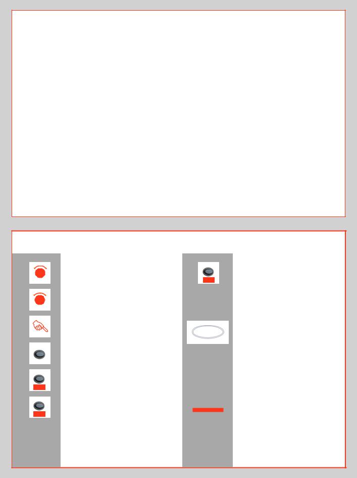
Some examples of various viewfinder displays visible with standard settings and when specific control buttons are pressed.
Standard settings |
|
|
Normalscreen |
NormalscreeninAElockstate |
Normal screen with |
|
|
exposure compensation set |
FLASH |
|
|
Flash mode |
|
|
|
|
|
AF |
|
|
AF mode |
|
|
|
|
|
DRIVE |
|
|
Drive mode |
|
|
|
|
|
MENU |
|
|
Menu mode |
|
|
+/– |
Exposurecompensationmode |
|
|
|
|
EXP |
|
|
Exposuremethodandmeteringmethod |
12
Menu charts – general
Throughout this manual you will find charts to explain the steps and procedures required to alter the various settings. These charts are laid out to graphically illustrate in a simple manner how to navigate through the menus. While they include all the information that would be presented on the display relevant to that section, they cannot illustrate all the possible combinations of the various symbols seen on a screen at one time as that would be impractical and too confusing. If you are familiar with mobile/ cell phone menus, for example, then the design of the layout and working practice will not be unfamiliar.
You should find that, in practice, working your way through a menu on the camera is a good deal simpler and more obvious than the written explanation implies!
In the descriptions, various terms are used regarding menu navigation.Menushave‘trees’,forexample,whichdescribestheirimaginary graphical layout where you could trace a navigational pathalongits‘branches’.Eachnewsection,orstoppingoffpoint onthebranches,seenonthedisplayiscalleda‘screen’.Therefore a screen is the graphical display of where you are on the menu and represents the current state of settings.
The H3D II features the advantage of multiple customization of settings. This means that your personal choice of settings, and thereby appearance of various combinations of symbols on the display at any time, will not necessarily be the same as many of the screens illustrated in this manual.
Tosimplifythedescriptions,referenceisoftenmadetoa‘main’ or standard screen. Apart from default settings, there is no actual standard setting in the normal sense and therefore you createyourown‘standard’,whichofcoursecanbechangedatany time.
The‘main’screenisthereforetheoneyouhavecurrentlycreated andistheonevisibleonthedisplaywhenphotographing(except where a particular mode is in actual operation, such as self-timer, forexample).
Symbols used in the charts
F |
Use front control wheel |
(direction depends on user setting)
R |
Use rear control wheel |
|
(direction depends on user setting) |
|
Press button or turn wheel |
MENU |
MENU button on the grip |
|
|
ISO/WB |
Choose ENTER |
|
|
Enter |
(by pressing ISO/WB button on grip) |
AF |
Choose ON |
|
|
On |
(by pressing AF button on grip) |
ISO/WB
Save
Choose Save
(by pressing the ISO / WB button on grip) The new setting will be saved and chosen action can be carried out. Setting will be retained until changed.
Functions in loop on menu
A loop means that the available functions on that particular branch of the menu can be successively accessed in either direction of the control wheels without a break in flow. That is, you could turn the wheel clockwise or anticlockwise to arrive at the desired function.
Main direction of path through menu
The main path traces step-by- step the path that has to be taken
through the various branches of the menu tree as they appear on the display to reach the relevant functions.
13
A
B C D E
F
G
H
I
Shutter release button |
A |
This button has half-press and full-press positions. By pressing half-way (or softly) the camera, auto focus function and exposure meter can be activated. By pressing all the way down (or more firmly) the shutter will be released (or the chosen exposure procedure will begin, as relevant. For example, the self timer is activated with this button)
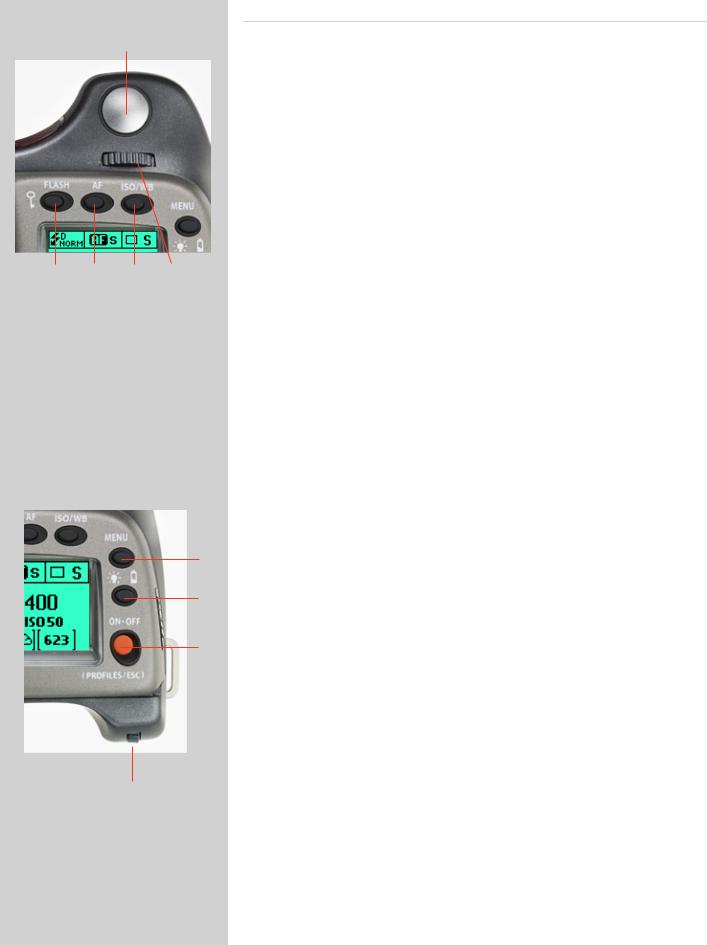
FLASH / (CONTROL LOCK) button / (EXIT) |
B |
This is a triple function button. If you press the button for one second, the beeper will sound (if set) and a key symbol will appear on the grip display signifying that the controls (except the shutter release) have been locked and therefore cannot be altered unintentionally in use. Press the button for one second again to unlock (this function can be altered to lock all controls or control wheels only in ‘Custom options’).
Quickly clicking the button will access the flash settings information on the display from the main screen. See separate section for full details.
This button also acts as the EXIT button for many other settings including an EXIT button when navigating the digital capture unit menu.
AF button / (ON) / (SEL.) |
C |
This is a triple function button. Press this button to directly access the autofocus/manual focus choice screen from the main screen. See separate section for full details. It also acts as the ON and SEL. (= select) buttons for many other settings.
ISO/WB button / (SAVE) / (ENTER) |
D |
This is a triple function button. It provides direct access to the ISO and White Balance settings (see separate section for full details).
It also acts as the SAVE and ENTER buttons for many other settings as well as an OK button when navigating the digital capture unit menu.
Front control wheel |
E |
The front and rear control wheels are used to make changes in exposure settings, access the various loop sections of the menu for settings as well as navigate the digital capture unit’s menu. The effect of the wheels’ direction is customizable.
MENU button |
F |
Accesses the first level of the menu for settings changes.
Illumination/Battery status button |
G |
Press to illuminate the display. Remains active until camera enters standby mode. Hold down to access battery status/general information screen.
ON.OFF (PROFILES/ESC) button |
H |
Press the button for 1 second to activate the camera. The H3D II start-up logo will appear and then the main screen. After a few seconds (customizable) the camera will enter Standby mode.
A long press of the button will turn the camera off completely (even from Standby mode) signified by an audible signal (if set). A quick ‘click’ on the button will access the Profiles section of the menu from the main screen.
Note the difference in results between a long press and a quick click of the this button.
Rear control wheel |
I |
The front and rear control wheels are used to make changes in exposure settings, access the various loop sections of the menu for settings as well as navigate the digital capture unit’s menu. The effect of the wheels’ direction is customizable.
14
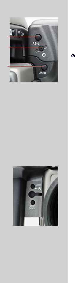
On the rear of the grip, as well as the rear control wheel, there are a further three control buttons:
AE-L button |
J |
J
K
This button can lock a light reading made in both automatic and manual exposure modes. It can also be used in Zone mode to take a new reading.
Can be reassigned in Custom Settings to another function.
See section on the AE-L button (“Light Metering and Exposure Control”) for full details.
Card format button |
K |
L
Re-formats the CF card. Purposefully recessed to prevent unintentional use. Dialogue appears for confirmation.
USER button |
L |
This button is purely user programmable to rapidly access a chosen function or screen. For example, you might use bracketing a great deal and so by one press of this button you could access the bracketing function without having to navigate through the menu. The AE-L, Mirror -UP and Stop Down buttons are also user-programmable but are by default initially assigned the functions according to their names
The reassignable capability of these buttons is particularly useful and can save you a great deal of time and effort depending on how you work. You are advised to investigatetheirpotentialfully.Seeunder‘Customsettings’forfulldetails.
On the front of the grip there are two more control buttons plus the remote cord release port:
|
|
|
|
M.UP button |
M |
M |
|
|
Press this button to raise the mirror and press again to lower it (toggle function). A quick |
||
|
|
double press of the button (two within a half second) will immediately access the ‘Self |
|||
|
|||||
N |
|
|
|
timer’ function. |
|
|
|
|
Can be reassigned in Custom Settings to another function. |
|
|
|
|
|
|||
O |
|
|
Remote release cord port |
N |
|
||||
|
|
|
For attaching a remote release cord (electrical). The Hasselblad accessory jack plug socket |
|
|
|
|
is protected by a captive rubber plug. |
|
|
|
|
STOP DOWN button |
O |
Press this button to make a visual check of the depth-of-field on the viewfinder screen at the chosen aperture. The aperture will close according to the setting and remain closed as long as the pressure is maintained. You can alter the aperture at the same time to see the changes taking place.
Can be reassigned in Custom Settings to another function.
15
P Q R
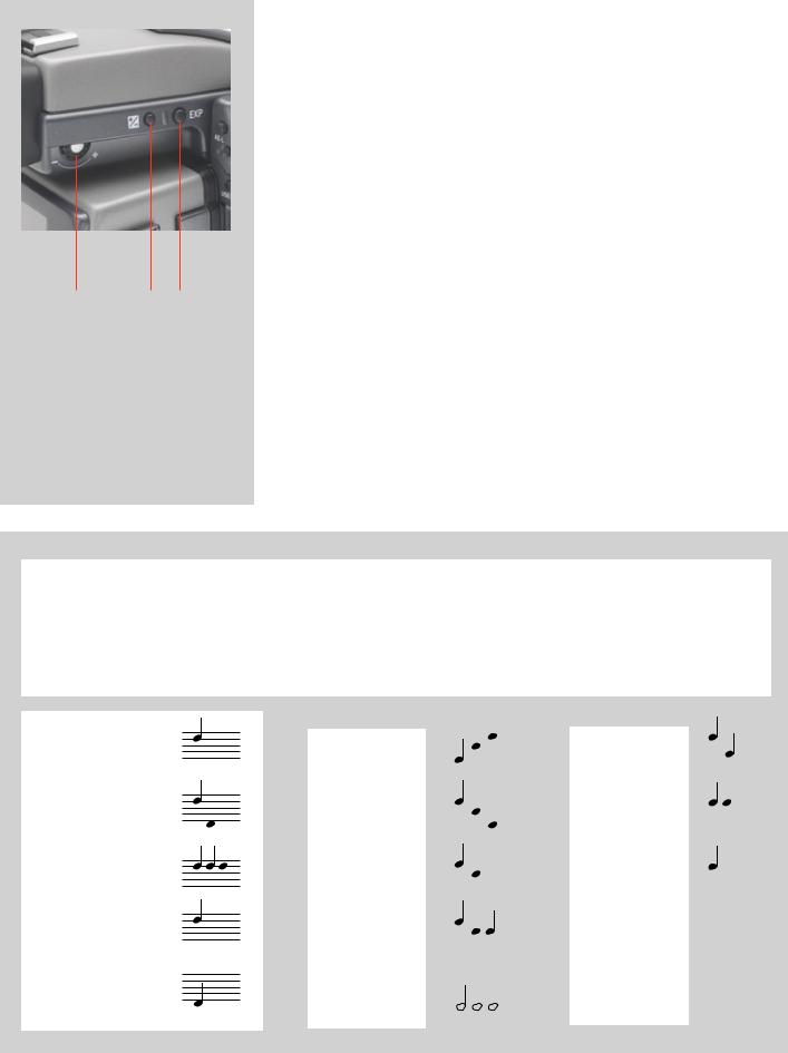
There are also two control buttons on the viewfinder, as well as the eyesight correction adjustment wheel:
Eyesight correction adjustment wheel |
P |
The personal eyesight adjustment facility has a diopter range of -5 to +3.5, to suit most users.
EV correction adjustment button |
Q |
Press this button to access the EV compensation screen. Settings are made with either the front or rear control wheels. An EV correction symbol appears on the grip and viewfinder display as confirmation.
EXP button |
R |
The EXP (Exposure) button accesses the exposure mode and metering method options screen. Settings are made with the front and rear control wheels and the appropriate symbols appear on the grip and viewfinder displays accordingly.
Audio feedback
Thereare14differentsoundstohelpprovideimmediateinformation.Abuttonpresshasanormalmechanical‘click’soundwhiletheremaining actions listed here are more musical. For example, a capture rated as overexposed is signified by three rapid notes going up the musical scale, whereas an underexposed capture has three rapid notes going down the musical scale, as illustrated here.
See later section about available options on the digital capture unit for activation and volume control.
ON:
ON:
OFF:OFF:
Error:ror:
Ready:Ready:
LowLowBatterybattery:
|
Overexposure: |
|
|
|
|
|
|
|
IAAAyellow: |
|
|
|
|
|
|
|
|
|
|
|
|||||||
|
|
|
|
|
|
|
|
||||||
|
|
|
|
|
|
|
|
||||||
|
|
|
|
|
|
|
|
||||||
|
Overexposure: |
|
|
|
|
|
|
|
|
||||
|
Underexposure: |
|
|
|
|
|
|
|
|
Overwritered:red: |
|
|
|
|
|
|
|
|
|
|
|
|
|
|
|
||
|
|
|
|
|
|
|
|
||||||
|
|
|
|
|
|
|
|
|
|
||||
|
|||||||||||||
|
|
|
|
||||||||||
|
|
||||||||||||
|
|
|
|
|
|||||||||
|
5 images left: |
|
|
|
|
|
|
|
Transfer complete: |
|
|
|
|
|
|
|
|
|
|
|
|
|
|||||
|
|
|
|
|
|||||||||
|
|
|
|
||||||||||
|
|
||||||||||||
|
|
|
|
|
|||||||||
|
|
||||||||||||
|
|
|
|
|
|||||||||
|
5 images left: |
|
|
|
|
|
r complete: |
|
|||||
|
1 image left: |
|
|
|
|
|
|
|
|
|
|
|
|
|
|
|
|
|
|
|
|
||||||
|
|
|
|
|
|
|
|
|
|
|
|
||
|
|
|
|
|
|
|
|
|
|
||||
|
|
|
|
|
|
|
|
||||||
|
|
|
|
|
|
|
|
||||||
|
1 image left: |
|
|
|
|
|
|
|
|||||
|
Media |
|
|
|
|
|
|
|
|
|
|
|
|
|
|
|
|
|
|
|
|
|
|
|
|
||
|
|
|
|
|
|
|
|
|
|||||
|
|
|
|
|
|
|
|
|
|
||||
|
Media fullfull: |
|
|
|
|
|
|
|
|
|
|
|
|
|
|
|
|
|
|
|
|
|
|
|
|
|
|
16

Customizable button function list
•The USER, AE-L, STOP DOWN and M.UP buttons can all be reassigned to different functions.
•The USER button has no function until specifically assigned one (default is ‘None’). The AE-L, STOP DOWN and M.UP buttons, however, by default are assigned the function appropriate to the name, until assigned otherwise, as follows:.
None
The user button has no function.
B mode
Sets the camera to B exposure mode.
Standby
Sets the camera in standby mode to save battery consumption.
Stop down
Stops the lens down to the chosen aperture.
Flash Measure
Initiates flash measure function.
T mode
Sets the camera to T exposure mode.
Histogram
Recalls the last shown histogram on the grip display.
Grey balance exp.
Initiates a grey balance exposure using the marker frame to select the desired tone.
Interval timer
Initiates interval timer function.
Self timer
Initiates self timer function.
Bracketing
Initiates bracketing function.
AF Drive
Activates the AF system in any focusing mode. When the button is pressed the AF system sets the correct focusing point automatically. This is a rapid, accurate and handy way of using the AF system when the camera is set to manual focus mode. In this manner you take advantage of the accuracy and certainty of the autofocus system while retaining the control inherent in manual focusing mode.
Mirror up
Cycle LM mode
Changes the light-metering method in a loop manner: Centre Weighted/CentreSpot/Spot.
Delete last image
Activates the delete function for the last capture.
Dig. foc check
Displays last capture at 100% scale to check focus.
IAA toggle
Allows IAA rating change of last capture.
Expose
Acts as alternative shutter release button.
AE-lock
Activates AE lock function.
Controls the mirror up or down function (same function as the M-UP button).
Aquickwaytoprogramthecustomizablebuttons(and toaccesstheCustomOptionlevelingeneral)istouse the short-cut as follows:
1) Press the MENU button.
2) Then press the USER button.
This directly accesses the “Custom options” level in the menu where you can access the desired option for a setting change.
17

2
Camera Body
Aluminium cast in one piece
Stainless steel shell
Integral quick-coupling plate
Digitally controlled
Upgradeable firmware
Modular design
Integral ergonomic grip
Pixel based user interface
The H3D II camera body is a robust construction of cast aluminium with a stainless steel shell for extreme durability.
Theintegralergonomicgriphousesthemaincontrolinterface and also contains the battery holder. The camera body also contains the viewfinder screen, which can be easily removed or exchanged without the use of special tools or adjustment procedures.
Please take extra care when handling the camera body without a protective cover or the digital capture unit in place to protect the auxiliary shutter. Likewise, the front opening of the camera body reveals the mirror when unprotected by a cover or lens. Do not touch or attempt to clean the mirror yourself—marks or dust particles will not impair results in any case. More noticeable problems, however, should be taken care of by a Hasselblad Authorized Service Center.
18
1 |
|
|
2 |
|
|
|
|
|
|
3 |
|
4 |
|
|
|
C
A1 
B
5
6
7
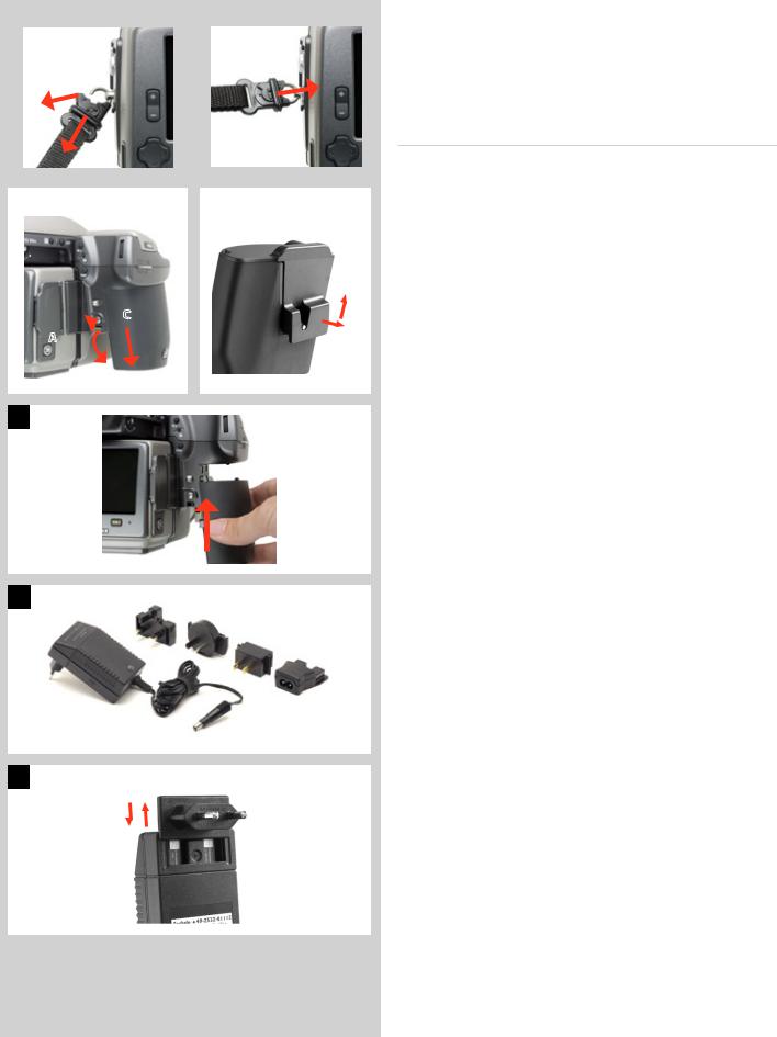
Carrying strap |
1, 2 |
The carrying strap is attached by firstly withdrawing the safety collar. The hook is then freed and attached to the strap lug (fig. 1). Slide back the safety collar (fig. 2) to ensure the hook remains in the locked position between the small protruding lugs. The collar is purposely a tight fit and might need some effort to slide.
Rechargeable battery grip
The Battery grip rechargeable 7.2V (3043348) is the standard power source for the H3D II camera and is an environmentally approved Li-ion type. The H3D II requires a power supply for all actions as there is no mechanical reserve facility. When working untethered, it is therefore advisable to keep the reserve battery grip complete with fresh lithium batteries handy (if you do not use a spare rechargeable battery grip). As is the case with most batteries, problems might be encountered when used in very low temperatures. In this situation it is advisable to keep the reserve battery in an inside pocket, for example, to maintain it near body temperature (both sorts of battery grips are referred to as the ‘battery’ in this manual).
Fitting and removing a battery |
3, 4, 5 |
The fitting and removing procedure is the same for both types of battery grip.
Remove the battery from the camera by depressing the battery holder button (A) and simultaneously swinging the battery holder retaining lever (B) down until it stops. Pull the battery downwards
(C).
If you intend to store the battery separately from the camera you should ensure that the safety cover is in place (to prevent shortcircuiting). It snaps into place and is removed by pulling outwards and upwards on the locking clip (fig. 4).
To fit, hold the battery flat against the camera body and aligning the two upper lugs with the slot, slide it back into position as far as it will go. Swing back the battery holder retaining lever until it clicks back into place.
Please note if you want to use the rechargeable battery with an H1/H1D model, the firmware in the camera must be version 8.2.2 or later for the battery grip to function properly.
The battery charger |
6, 7 |
The battery charger unit is supplied with five plug attachments to suit various types of domestic electrical sockets available worldwide. Other types of socket will require a domestic socket converter. Attach the chosen plug (fig 7) by sliding it into position, ensuring that the two electrical contact prongs on the charger correctly enter the two contact sockets on the plug attachment. Removal is by the reverse procedure.
Please note the Battery charger BC-H Li-ion 7.2 VDC (3053568) is designed for use with Battery grip rechargeable 7.2V units only.
19
|
|
|
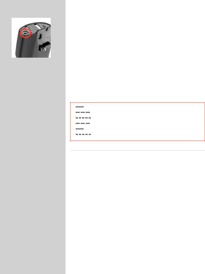
Charging the battery |
|
8 |
|
|
|
With the battery removed from the camera, insert the jack plug from the battery charger |
||
8 |
|
|
|||
|
|
|
into the socket on the battery grip. Insert the battery charger into a standard (100–240V~ |
||
|
|
|
|||
|
|
|
/50–60 Hz) domestic socket. |
|
|
|
|
|
It will take about 12 hours to load the battery properly the first time. |
||
|
|
|
There are two types of battery charger. Please check here for the relevant description of |
||
|
|
|
the LED indicator, etc. |
|
|
|
|
|
|
|
|
|
|
|
On (not flashing) |
|
Battery is charging |
|
|
|
Slow flashing (0.8 Hz) |
|
Charging is complete and condition is being maintained. |
|
|
|
Or occasionally |
|
|
|
|
|
|
||
|
|
|
Rapid flashing (3 Hz) |
Deeply discharged battery is charging (with reduced current) |
|
|
|
|
Please note that rapid flashing of the LED indicator is not to be expected. The bat- |
||
|
|
|
tery will not normally be so deeply discharged because the camera will shut down |
||
|
|
|
automatically before complete battery discharge takes place. The indicator might |
||
|
|
|
also flash rapidly for a few moments in some instances when the charger is connected |
||
|
|
|
to the electrical supply. The normal indication is therefore either ‘not flashing’ or |
||
|
|
|
‘slow flashing’. |
|
|
—
– – –
- - - - -
– – –
—
- - - - -
continuous yellow |
|
Standby |
slow flashing yellow |
|
Pre charge |
rapid flashing green |
Charging ( <75% ) |
|
slow flashing green |
Charging ( >75% ) |
|
continuous green |
Ready ( 100% ) |
|
rapid flashing yellow |
|
Fault condition |
Rechargeable battery grip – general
•Thebatteryshouldbechargedforapproximately12hoursbeforefirsttimeuse.
•Thebatteryisbestchargedatanambienttemperatureof10°−45°C(50°−113°F).
•Maximumbatterycapacityisreachedonlyafterthebatteryhasbeenchargedanddischargedseveraltimes.
•Avoidfrequentfulldischarges(afulldischargeissignalledbytheappearanceofthe‘Replacebattery’warningon thegripdisplay).AsthebatteryisaLi-iontype,ithasno‘memoryeffect’ofpracticalimportanceandtherefore frequentrechargeswillcausenoproblemssuchaslossofcapacityorpoorperformance.Itisthereforebetter policytorechargethebatteryatveryregularintervals,regardlessofuse.
•Removethebatteryifyouintendtostorethecameraforsomewhileasitwilleventuallybecomecompletely drained,eventhoughthecameraisturnedoff.
•Thebatteryhasanintegrated‘fuelgauge’capabilitythatsupportsthe‘Replacebattery’and‘Batterystatus’func- tionsonthegripdisplay.AswithmostLi-ionbatteries,thiscapabilityshouldbeoccasionallycalibrated,depending onhowmuchthebatteryisused.Todothis,leavethecameraon(oruseit),untilthe‘Replacebattery’warning appears.Then,rechargethebatteryfor12hours.Thiswillimprovetheaccuracyofthemeasurements.
•Whenremovingabatteryfromthechargerandimmediatelyreplacingitwithanother,allowafewsecondsto elapsesothatthechargercanautomaticallyresetforthenextchargingprocedure.
•Itisperfectlynormalforthebatterytobecomewarmwhenbeingcharged.
•Aslighttemporarylossofbatteryperformancemightbenoticedatveryhighorlowtemperatures.Takethe appropriatemeasuresifthisisthecase.
•Ifyoudonotintendtousethebatteryforawhile,itisbesttostoreitatroomtemperaturewithanapproximate 30to40%charge.Youcancheckthepercentagelevelonthestatusscreen.
•AccordingtotheCIPAstandard,200shotsshouldbeexpectedfromafullychargedbattery,thoughthisdepends oncamerause.Inpractice,however,withshortintervalsbetweenshots1,000shotscanbeachieved.
•Thebatteryshouldhaveauseableservicelifeofaround400recharge/dischargecycles.
20
9
10
11
12
Camera battery warning
13
ImageBank-ll battery warning
14
Rechargeable battery grip – precautions
The following precautions should be followed:
•Connectthebatterygriptothecameracorrectly.
•Keeptheprotectivecoverinplacewhennotinuse.(Short-circuitingacrosskeysinapocket,forexample, couldcauseafirerisk).
•DonotusethebatterygripforanythingotherthananH1/H1D/H2/H2Dcamera.
•Donotimmersethebatterygripinliquids.
•Donotincineratethebatterygrip.Pleaserecycleordiscardinanenvironmentallyapprovedmanner.
•DonotuseanyotherchargerthantheHasselbladbatterychargerBC-HLi-ion7.2VDC(3053568).
BatterychargerBC-HLi-ion7.2VDC:
•Readtheinstructionsbeforeusingthecharger.
•Useindoorsonly(protectagainstmoisture).
•DonotusechargerforanythingelsethanchargingofBatterygriprechargeable7.2V(3043348).
•Donotshort-circuitthejackplug.
•Donotalterthechargerinanywayotherthanchangingtheplugattachment.
Reserve lithium-battery grip (31 and 39 Mpixel models only) |
9, 10 |
The reserve lithium-battery grip is attached and removed in the same manner as the rechargeable grip.
Press the red battery cassette retaining button inwards on the holder to release the battery cassette (fig 9). Load three CR-123 lithium (or equivalent) into the cassette, ensuring the polarity of each battery is correctly oriented (see the ‘+’ markings on the batteries and the cassette) (fig 10, 11). Re-insert the cassette into the battery holder, ensuring that it is seated properly in place and that the red button returns fully into the locked position. Holding the battery flat against the camera body and aligning the two upper lugs with the slot, slide it back into position as far as it will go. Swing back the battery holder retaining lever as far as it will go into the locked position.
Do not use a lithium-battery grip with the 50 Mpixel model.
Battery life |
11, 12, 13, 14 |
Battery life is dependent on a number of variable factors and therefore cannot be exactly predicted. If the camera is left in the active state instead of standby for long periods, for example, then the battery will become exhausted much faster.
A low camera battery state is indicated by a symbol on the grip display (fig. 11) as well as on the digital capture unit display (fig. 12). In addition, an audible signal can be heard.
The warning on the display (fig. 12) appears as a flashing yellow icon in the top right of the screen signifying that the battery should be charged (or changed) as soon as possible. The warning icon will also appear with a FireWire connection and will in addition turn red to signify that the camera battery is completely exhausted.
Another battery warning also appears signifying ImageBank-II battery exhaustion (fig.
13). This icon appears on the top left of the display screen. It too flashes yellow as the initial warning and changes to red to signify complete exhaustion.
When the battery is almost completely exhausted, a warning message ‘Replace battery’ will appear on the grip display (fig. 14).
Whenthe‘Lowbattery’iconappears,thecameraautomaticallyentersatemporary power-saving mode. This is recognizable by a slower pace for all the actions in a capture sequence. The camera actions also sound differently .
This mode is designed so that you can continue working for a while, even though the power remaining in the battery is too low for working in the normal manner. Naturally, you should replace the battery as soon as possible to restore normal action again.
21
|
|
|
|
|
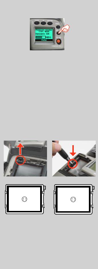
Battery status (rechargeable battery only) |
15 |
|
|
|
|
|
An immediate full-screen information and battery status check |
|
15 |
|
|
|
|||
|
|
|
|
appears on the grip display by holding down the illumination/ |
||
|
|
|
|
|
battery status button. This screen displays: |
|
|
|
|
|
|
• thefirmwareversion |
|
|
|
|
|
|
• thenumberofcapturestakensincethelastbatteryrecharge/change. |
|
|
|
|
|
|
||
|
|
|
|
|
||
|
|
|
|
|
• arechargeable-batterystatusiconthatprovidesaquickvisualcheckaswellasa |
|
|
|
|
|
|
figureestimateinpercent. |
|
|
|
|
|
|
The information regarding the number of captures taken is intended |
|
|
|
|
|
|
to help you make an estimate of the number of possible remaining |
|
|
|
|
|
|
captures according to your way of working. For example, if you |
|
|
|
|
|
|||
|
|
|
|
|
regularly browse a great deal when shooting or you leave the camera |
|
|
|
|
|
|
in ON-mode with no standby, you would naturally expect to drain |
|
|
|
|
|
|
the battery sooner than others who don’t. You should soon be able |
|
|
|
|
|
|
to build up a picture of how you usually work and can therefore |
|
|
|
|
|
|
estimate that after X number of captures, you normally expect to |
|
|
|
|
|
|
be able to take Y captures before the battery is exhausted (when |
|
|
|
|
|
|
working in a similar manner in similar conditions). |
|
|
|
|
|
|
The percentage information, however, provides another kind of |
|
|
|
|
|
|
estimate based more on the amount of power left in the battery |
|
|
|
|
|
|
rather than on your normal way of working. |
|
|
|
|
|
|
Remember that these are only estimates and that there are a number |
|
|
|
|
|
|
of factors affecting remaining battery, ambient temperature for |
|
|
|
|
|
|
example, as well as general practice. |
|
|
|
|
|
|
|
|
|
|
|
|
|
Viewfinder screen |
16, 17 |
|
|
|
|
|
|
|
|
|
|
|
|
The H3D II is fitted with a Spherical Acute-Matte D viewfinder |
|
16 |
|
|
|
|
|
17 |
|
|
|
|
|
screen for extreme brightness, clarity and even illumination. An |
|
|
|
|
|
|
|
|
|
|
|
|
|
optional accessory screen with a grid pattern is also available. |
|
|
|
|
|
|
|
|
|
|
|
|
|
To change a viewfinder screen, remove the viewfinder to access the |
|
|
|
|
|
|
|
|
|
|
|
|
|
||
|
|
|
|
|
|
|
|
|
|
|
|
viewfinder screen. To remove the screen, place the tip of a ballpoint |
|
|
|
|
|
|
|
|
|
|
|
|
|
pen or similar in the viewfinder screen removal lug and pull up- |
|
|
|
|
|
|
|
|
|
|
|
|
|
||
|
|
|
|
|
|
|
|
|
|
|
|
wards. To replace the screen, position the right side of the screen in |
|
|
|
|
|
|
|
|
|
|
|
|
|
place so that it sits correctly in the recess. Place the tip of a ballpoint |
|
|
|
|
|
|
|
|
|
|
|
|
|
pen or similar in the viewfinder screen replacement indentation and |
|
|
|
|
|
|
|
|
|
|
|
|
|
press downwards until the screen snaps into position. Try to avoid |
|
|
|
|
|
|
|
|
|
|
|
|
|
touching either surface of the screen with bare fingers. |
|
|
|
|
|
|
|
|
|
|
|
|
|
Do not attempt to clean the screen by immersing it in water, or |
|
|
|
|
|
|
|
|
|
|
|
|
|
||
|
|
|
|
|
|
|
|
|
|
|
|
||
|
|
|
|
|
|
|
|
|
|
|
|
||
|
|
|
|
|
|
|
|
|
|
|
|
use any kind of cleaning fluid. If the screen becomes damp, do |
|
|
|
|
|
|
|
|
|
|
|
|
|
notusehotairtodryit.Useasoftclothontheuppersurfaceonly. |
|
|
|
|
|
|
|
|
|
|
|
|
|
Seek advice from an Authorized Hasselblad Service Center if the |
|
|
|
|
|
|
|
|
|
|
|
|
|
screen becomes particularly soiled. Remember that particles or |
|
|
|
|
|
|
|
|
|
|
|
|
|
||
|
|
|
|
|
|
|
|
|
|
|
|
greasy marks on the screen might impair the viewfinder image |
|
Viewfinder screen showing |
Viewfinder screen showing com- |
but have no effect whatsoever on the recorded image. |
|||||||||||
composition frame marking |
positionframemarking(31MPix). |
|
|
||||||||||
(22/39/50MPix). |
|
|
|
|
|
|
|
|
|||||
22
18 |
|
|
19 |
|
|
|
|
|
|
20
21 |
22 |
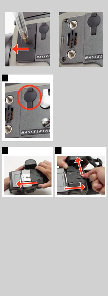
Accessory connection |
18, 19 |
On the left hand side of the camera body are two accessory-retaining screw threads (M5), as well as a databus connector, protected beneath a cover.
The cover can be removed by inserting a pointed object, such as a pen, in the small hole and then sliding it to the left, as in the illustration. The cover-retaining clip can then also be removed to access the connector.
PC-connector |
20 |
A PC connector for non TTL-flash synchronisation is located on the left side of the body. It is protected by a captive rubber plug.
Protective base plate |
21, 22 |
To attach the protective base plate, slip it over the camera foot until it stops. To remove it, lift the securing catch while pushing the plate back as in the illustration.
23

3
Viewfinder
Multi-mode light metering
Full exposure information
100% image
90° viewing angle for eye-line composition
Full image for spectacle wearers
Integral dioptre adjustment
Integral flash unit
The HVD 90X viewfinder provides a laterally corrected 100% image at eye-line level. It features a wide-range diopter adjustment to suit most users. The viewing distance is designed to provide full frame view even for eyeglass wearers. The brightSphericalAcute-MatteDfocusingscreens(locatedin the camera body) are interchangeable to suit preference, each of them naturally indicating the spot light-metering area for accuracy in exposure calculation. The information display located beneath the viewing frame is continually updated and visible and is back lit for optimum visibility. This display also duplicates much information visible on the grip display for immediate checking. In addition to the display, there are four LEDs providing general warnings, flash and focus information. The viewfinder also features a pop-up fillflash unit for added convenience.
24
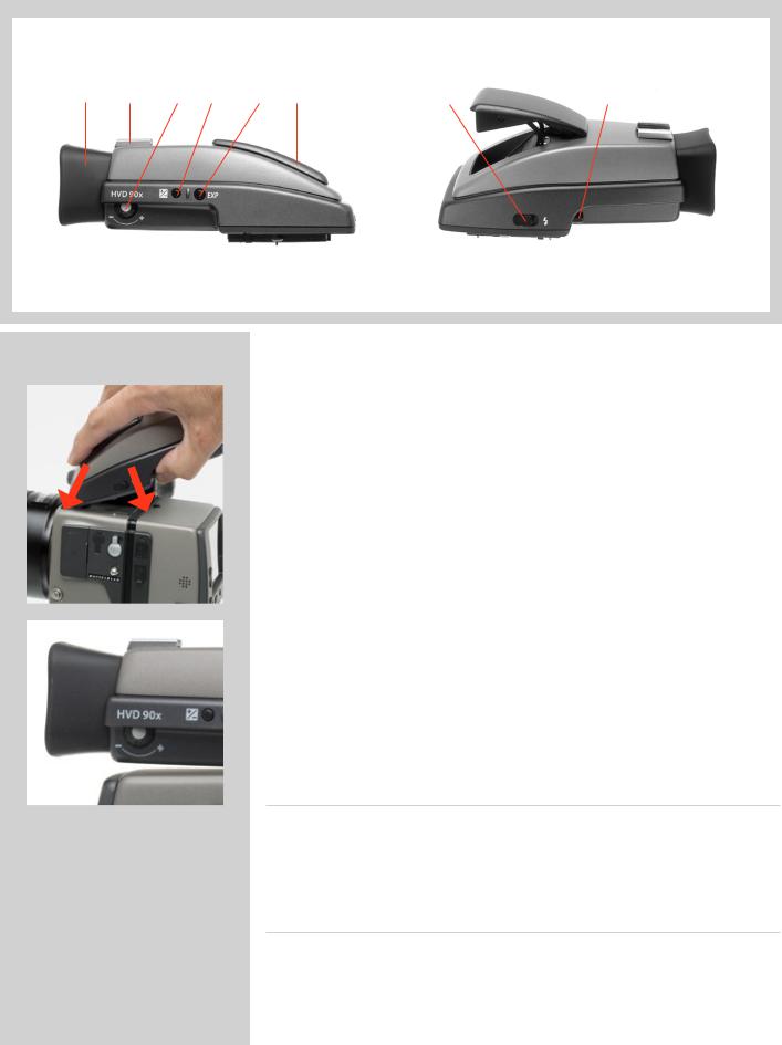
Parts and components
A B C D E F G H
A. |
Rubber eye cup |
D. |
Exposure compensation button |
G. |
Flash unit button |
B. |
Hot shoe |
E. |
Exposure method / mode button |
H. |
Viewfinder release button |
C. |
Eyesight adjustment wheel |
F. |
Integral flash unit |
|
|
|
|
|
Attaching and removing the viewfinder |
1 |
|
|
|
While holding the viewfinder at a slight angle and resting it on the top of the camera, |
|
|
|
|
slide the viewfinder forward until the front locating pin is in position in the recess in |
|
1 |
|
|
||
|
|
the front edge of the viewfinder screen aperture on camera body. Press the rear part of |
||
|
|
|
||
|
|
|
the viewfinder firmly downwards until it clicks into place. |
|
1 |
2 |
Ensure that both sides of the viewfinder are seated correctly and that it has been firmly |
||
attached and locked into position. Failure to do so could cause an intermittent malfunc- |
||||
|
|
|
tion if the databus interface connections between the viewfinder and camera body are |
|
|
|
|
not positively secured. |
|
|
|
|
To remove, grasp the viewfinder in the right hand and while depressing the viewfinder |
|
|
|
|
release button, lift the rear of the viewfinder up and away from the camera body. |
|
|
|
|
Eyepiece adjustment |
2 |
|
No corrective lenses are needed to adjust the eyepiece to suit most requirements. |
|
|
The diopter range is from -5 to +3.5. Eyeglass wearers can rapidly and accurately change |
|
|
the settings according to whether they wish to wear eyeglasses for viewing or not. |
|
2 |
||
Personal eyepiece adjustments can be carried out by pointing the camera at the sky or |
||
|
||
|
similar smoothly toned area. While holding the camera in your left hand, you can with |
|
|
your right thumb turn the adjustment wheel until the markings on the viewfinder screen |
|
|
reach the optimum sharpness for your eyesight. |
|
|
If you normally wear eyeglasses for distance viewing and intend to wear them for camera |
|
|
use then do not remove them for the above procedure. If, on the other hand, you prefer |
|
|
to remove your eyeglasses for camera work, then repeat the above procedure without |
|
|
wearing your eyeglasses. |
Rubber eye cup
Two rubber eye cups are available for the H3D II. The one supplied is suitable for users who do not intend to use eyeglasses when photographing. The second shorter eye cup is for those who either prefer to position their eye further from the viewfinder and those who wish to wear eyeglasses.
The eye cups can be rapidly changed by a Hasselblad Authorized Service Center.
Integral flash unit
See section on ‘Flash’ for full details.
25

4
Lenses
Rapid and accurate automatic focusing capability
Central electronic shutter
Instant manual focus override with natural friction
Instant automatic-focus access in manaul mode
Non-rotation of filter or accessory when focusing
Non-rotation of focus ring in automatic focusing mode
Flash sync at shutter speeds from 32s to 1/800s
Reversed lens shade serves as protection
Automatic detection of extension rings and converters
All HC lenses have been specially formulated for the H system to produce the extremely high performance expected from Hasselblad to meet the demands from digital photography alike. In addition to extreme sharpness, the design also incorporatesasoft,pleasantlookingboké(thevisualquality of the out-of-focus areas of the image). All lenses feature an electronically controlled central shutter designed to extremely fine tolerances for supreme accuracy. To ensure reliable and fast autofocus in low contrast and low light con- ditions,afocusing-assistlight(onthegrip)isautomatically activated. Aperture and shutter control is set via the control wheels on the camera grip.
As a general rule, lens shades should always be fitted to achieveoptimumperformance.Protectivefilters(UV/Sky) should also be considered at least when working outdoors in harsh conditions.
(SeeAccessoriessectionforinformationabouttheCFAdapter that allows the use of C type lenses from the Hasselblad
V-system).
26
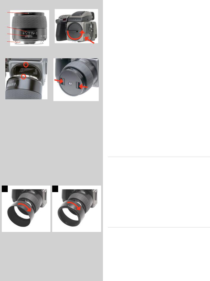
|
|
|
|
|
|
|
|
|
|
|
|
|
|
|
|
|
Parts and components |
1 |
|
1 |
|
|
|
2 |
|
||||
A |
|
|
|
|
A. |
Lens shade index |
|
||
|
|
|
|
|
|
|
|
||
B |
|
|
|
|
|
|
B. |
Manual focus ring |
|
|
|
|
|
|
|||||
C |
|
2 |
|
C. |
Focusing distance scales |
|
|||
|
|
D. |
Depth-of-field scales |
|
|||||
|
|
|
|
|
|
|
|
||
D |
|
|
|
|
E. |
Lens index |
|
||
E |
|
1 |
|
Attaching a lens |
2, 3 |
||||
|
|
|
|
|
|||||
|
|
|
|
|
|
|
|
||
|
|
|
|
|
|
|
Remove the front protective cover on the camera body by depressing |
||
3 |
|
|
|
4 |
|
||||
|
|
|
|
|
the lens release button and keeping it depressed while turning the |
||||
|
|
|
|
|
|
|
|||
|
|
|
|
|
|
|
cover counter-clockwise. Remove the rear lens cap by unscrewing |
||
|
|
|
|
|
|
|
it in a counter-clockwise direction. Align the index on the lens |
||
|
|
|
|
|
|
|
with the index on the camera body and rotate the lens clockwise |
||
|
|
|
|
|
|
|
(bayonet fitting) until it clicks into place. |
|
|
|
|
|
|
|
|
|
Removing a lens |
|
|
|
|
|
|
|
|
|
Depress the lens release button and keep it depressed while rotat- |
||
|
|
|
|
|
|
|
ing the lens counter-clockwise until it stops and lift it out. Replace |
||
|
|
|
|
|
|
|
protective caps on the lens immediately and on the camera body |
||
|
|
|
|
|
|
|
if necessary. |
|
|
|
|
|
|
|
|
|
|||
|
|
|
|
|
|
|
If you try to rotate the lens before you press the lens release button, |
||
|
|
|
|
|
|
|
it might lock. In this case, rotate the lens clockwise a little first |
||
|
|
|
|
|
|
|
and then re-attempt removal with the correct procedure: button |
||
|
|
|
|
|
|
|
first, then lens. |
|
|
|
|
|
|
|
|
|
Front lens cap |
4 |
|
|
|
|
|
|
|
|
Front lens caps are released for removal and attachment by insert- |
||
|
|
|
|
|
|
|
ing a thumb and index finger into the recesses and pinching in the |
||
|
|
|
|
|
|
|
direction of the arrows. |
|
|
Filters
Filters have a screw thread fitting (67 / 77 / 95 mm, according to lens) and are screwed clockwise into place. As there is no rotation of the front section of the lens when focus is changed, filters do not rotate either. This is particularly useful when using polarizing or graduated filters where the orientation is normally critical.
5 |
6 |
Lens shades |
5, 6 |
|
|
|
|
||
All lenses are supplied with lens shades that additionally provide extra protection for transport and storage when mounted in reverse. Lens shades have a bayonet fitting and are turned clockwise into place after ensuring the index on the lens shade aligns with the index on the front of the lens. When mounted in reverse, they are attached by matching the indexes and turning clockwise.
Shutter and aperture control
Both the shutter and aperture are electronically controlled and are adjusted by the control wheels on the grip. There are no separate manual setting rings on the lenses or camera body.
The chosen settings are displayed both on the grip display and in the viewfinder display. See the ‘Exposure Control’ chapter for a complete explanation.
27
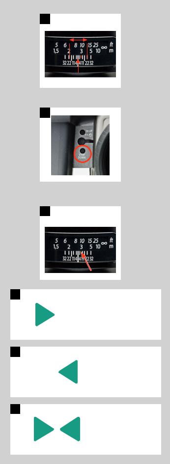
7
8
9
10
Lens focus setting too far beyond the distance of the subject framed by the central section in the viewfinder
11
Focus setting too close for the distance of the subject framed by the central section in the viewfinder
12
Focus setting correct
Depth-of-field calculation |
7 |
There are two distance scales (in feet and metres) visible through the focus distance window on the upper part of the lens barrel. There is also a central lens index mark and a depth-of-field scale. The focusing distance is read off the chosen scale from the central lens index.
Depth-of-field can be calculated as follows:
1.Focus the lens as required.
2.Make an exposure reading (auto or manual) and note the aperture setting.
3.Find the markings on either side of the central index that correspond to the chosen aperture.
4.From these two markings, read off on the required lens distance scale the two corresponding distances.
5.The depth-of-field (at that particular aperture and focus setting) will be the area included between these two distances.
In the example given here, the focusing distance is set at nearly 3 metres. At an aperture of f/22, the depth-of-field would therefore extend from just over 2 m to approximately 4.5 m. Note that depth of field is not an absolute. Perception of it depends on several factors and so it should be seen only as a rough guide.
Stop down / depth-of-field |
8 |
A visual depth-of-field preview can be made by depressing the STOP DOWN button while viewing the image on the viewfinder screen.
Infrared focus settings |
9 |
As infrared rays form an image at a different plane to that formed by visible light, the normal focus settings do not apply. Proceed as follows in manual focus mode:
1.Focus the lens in the conventional manner until satisfied.
2.Note the distance setting against the central lens index.
3.Re-align this distance setting against the infrared mark
(coloured red) instead of the central lens index.
Alternatively if you have already calculated the required distance, you can make a manual distance setting by using the distance scales together with the infrared mark instead of the central lens index.
Focus aid |
10, 11, 12 |
As well as the conventional view on the focusing screen to ensure a sharp image, the H3D II also features LED focus aid capability appearing as two arrowheads to the right of the viewfinder display (except for lenses with a maximum aperture of f/6.7 or smaller). The arrowheads provide confirmation of a precision focus setting and are a useful aid when making a setting with eyesight alone.
Manual focus setting
When the left arrowhead alone appears it means the focus setting is too far beyond the chosen distance (the area framed within the central zone in the viewfinder) and when the right arrowhead alone appears it means the focus setting is too close. Focus is correct when both arrowheads appear together. If the focus cannot be established, then both arrowheads flash.
28
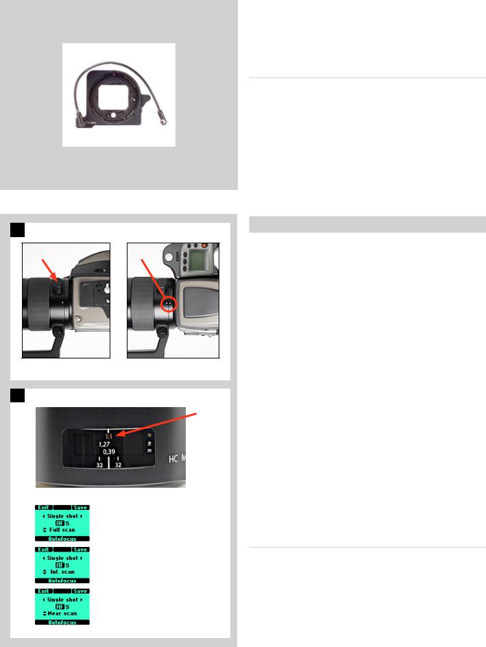
1 HC 3.5 / 300 |
|
A |
B |
Landscape orientation Portrait orientation
2 |
HC 4 / 120 (Macro) |
A |
|
||
|
|
Full scan |
= 0.39 m – ∞ |
Inf. scan |
= 0.9 m – ∞ |
Near scan |
= 0.39 m – 1m |
Automatic focus setting
Focus is correct when both arrowheads are visible together. Focus is incorrect if only one arrowhead is visible. If the focus cannot be established, then both arrowheads flash.
CF Adapter
The CF adapter is an optional accessory that allows virtually all C type lenses from the V-system to be used on H-system camera bodies. This provides an economical alternative way of extending the lens range. The automatic focusing system in the H camera can be used as a guide for manual focus setting. Light is measured at full aperture with all lenses which produces aperture and shutter speed information display in the camera for manual setting. With CFE lenses, however, a preset aperture is automatically transferred to the camera. Shutter cocking is manual with all lenses and is swiftly carried out by an easily accessible lever.
Specific-lens information
HC 3.5 / 300 |
1 |
When using a tripod with a 300mm you should use the (removable) tripod mounting bracket to provide optimum balance. This is attached via a sleeve so that the camera body can be rotated for landscape/portrait formats without altering the tripod head position. The rotation is secured by a locking screw (A). Correct 90° orientation can be ensured by aligning white index markers
(B) for both landscape and portrait orientations.
HC 4/120 (Macro) |
2 |
In addition to the metres/feet scale, the 120 mm lens also displays magnification ratio scale (A). In the illustration, the scale shows a focusing distance of 1.27 feet / 0.39 metres which in turn produces a 1:1 (lifesize) magnification.
With the 120mm lens mounted on the camera, addition screens will appear on the grip display when autofocus is chosen to signify a focus limit setting. Three are available – Full scan, Infinity scan and Near scan – accessed by the rear control wheel. This time-saving function is a form of presetting that restricts the scanning range of the lens to prevent it searching across the whole focus scale. Simply make a rough assesment of the approximate focusing distance and then choose the most suitable of the three ranges. The lens will then be able to find the critical focus much faster.
HC 3.5–4.5/50–110 Zoom lens
Please read the advice that is included with this lens before use regarding how it should be placed or stored.
29

5
General overview of digital capture unit
3 operating and storage modes
Direct shooting to 3FR
Phocus / FlexColor
Instant Approval Architecture
H system cameras were designed with digital photography in mind right from the outset so the H3D II is a natural development within the world famous H system.
Seamless integration and consequently increased efficiency and improved workflow are the results of such a design that features shared information visible on the displays as well as a shared battery, for example.
Phocus, the image processing software that is included with an H3D II, can take advantage of the information that is stored with each capture both for future reference and for enhanced processing to fine-tune optical characteristics, for example.
Phocus also provides for tethered use allowing digital capture control directly from the computer.
30
 Loading...