


User Manual
503CW/503CWD/CFV/CFVII/CFV-39/CFV-50
Version 10
Welcome to Hasselblad
503CW
503CWD CFV
2

C O N T E N T S
|
Introduction |
4 |
|
503CW |
|
1 |
General information |
6 |
|
|
|
|
Par ts & components |
7 |
2 |
Camera body |
9 |
|
Front protec tive cover |
10 |
|
Rear cover MultiControl |
10 |
|
Opening the focusing hood |
10 |
|
Built-in magnif ier |
10 |
|
Focusing screen and view f inder image |
10 |
|
Closing the focusing hood |
10 |
|
Winding crank |
11 |
|
Accessor y rail |
11 |
|
Strap at tachment and removal |
11 |
3 |
Lenses |
12 |
|
|
|
|
Shut ter speed and aper ture |
13 |
|
At taching the lens |
13 |
|
Removing the lens |
14 |
|
E xposure |
14 |
|
Warning mark |
14 |
|
E xposure values |
14 |
|
Interlocked shut ter speed /aper ture |
14 |
|
Focusing and depth of f ield |
14 |
|
Depth of f ield preview |
15 |
|
Pre -release and cable release |
15 |
|
Flash /strobe synchronization |
15 |
4 |
The Viewfinder System |
16 |
|
|
|
|
Changing the focusing hood or view f inder 17 |
|
|
Changing the magnif ier |
17 |
|
Changing the focusing screen |
17 |
5 |
Film Magazines |
18 |
|
|
|
|
Par ts & components |
19 |
At taching and removing |
19, 20 |
Magazine status indicator |
20 |
Film loading |
20 |
Film tab holder |
21 |
Film plane position |
21 |
Double exposure |
21 |
Flash / strobe with f ilm |
21 |
Set ting f ilm speed for T TL /OTF f lash |
22 |
View f inder indicator |
22 |
Flash adaptor |
22 |
Infrared f ilm |
22 |
6 Accessories |
24 |
|
|
Rear cover MultiControl |
25 |
Technical Specif ications |
27 |
Troubleshooting |
27 |
CFV
1 Overview |
28 |
|
|
Int r o d uc tio n |
29 |
Before you star t |
30 |
Computer system requirements |
31 |
Warnings and restric tions |
31 |
Parts, components & control panel buttons |
32 |
Bat ter y |
34 |
At taching and removing |
36 |
On/of f but ton |
36 |
Bat ter y warning |
36 |
Flash/strobe |
37 |
Over view menu/navigation/set tings |
39 |
Over view menu struc ture |
40 |
Over view storage/set tings |
41 |
2 Getting started |
42 |
File storage |
43 |
ImageBank-II |
4 4 |
CF cards |
45 |
Tethered to a computer |
46 |
Initial set tings |
47 |
ISO |
48 |
White balance |
48 |
Media |
49 |
Browse |
50 |
Shor tcuts |
50 |
3 |
Previews |
51 |
|
7 |
Settings |
72 |
|
|
Preview modes |
52 |
|
|
User inter face |
74 |
|
4 |
Batches & browsing |
55 |
|
|
Camera |
75 |
|
|
|
|
|
|
About |
82 |
|
|
Batches |
56 |
|
|
|||
|
|
|
Custom options |
83 |
|||
|
Current batch |
56 |
|
|
|||
|
|
|
|
|
|
||
|
Creating a new batch |
57 |
|
8 |
Cleaning |
85 |
|
|
Browse |
57 |
|
9 |
Appendix |
87 |
|
|
Basic image browsing |
58 |
|
|
|
|
|
|
|
Technical specifications |
88 |
||||
|
Navigating batches |
59 |
|
|
|||
|
|
|
Equipment care and service |
89 |
|||
|
Browsing batches |
60 |
|
|
|||
|
|
|
Further reading |
89 |
|||
|
Thumbnail views |
60 |
|
|
|||
|
|
|
|
|
|
||
|
Viewing modes |
60 |
|
|
|
|
|
5 |
IAA |
61 |
|
|
|
|
|
|
|
|
|
|
|
|
|
|
Using Instant Approval Architec ture |
62 |
|
|
|
|
|
|
|
|
About this manual |
|
|
||
|
Standard Instant Approval work f low |
62 |
|
|
|
|
|
|
|
|
This manual describes how to work with |
||||
|
Default approval status |
64 |
|
|
|||
|
|
|
Hasselblad 503CW/503CWD model cameras |
||||
|
Browsing by approval status |
65 |
|
|
|||
|
|
|
and Hasselblad CFV digital backs. CFV-39 and the |
||||
6 |
Delete, Format, Copy |
66 |
|
|
|||
|
|
CFV-50 digital backs are the currently available |
|||||
|
|
|
|
|
models and are therefore reflected in this manual |
||
|
Deleting single images |
67 |
|
|
|||
|
|
|
together with the current firmware update (as |
||||
|
Deleting by Approval status |
68 |
|
|
|||
|
|
|
of 09/2011). Please refer to previous manuals |
||||
|
Deleting several images from a batch |
69 |
|
|
|||
|
|
|
for details concerning older firmware versions. |
||||
|
Deleting several images from a CF card |
70 |
|
|
The manual explains specific practical aspects of |
||
|
Copy |
71 |
|
|
camera operation and control, the menu system |
||
|
Format |
71 |
|
|
and suchlike details regarding these products. |
||
It is assumed that reasonable levels of general analogue and digital photographic knowledge as well as computer skills are already acquired, so these are not dealt with here.
Not all the images in this manual were taken with a Hasselblad 503CW/CFV. They are used for illustrative purposes only and are not intended to represent the image quality produced by a Hasselblad product. © Jens Karlsson, David Jeffery and Ove Bengtson.
3
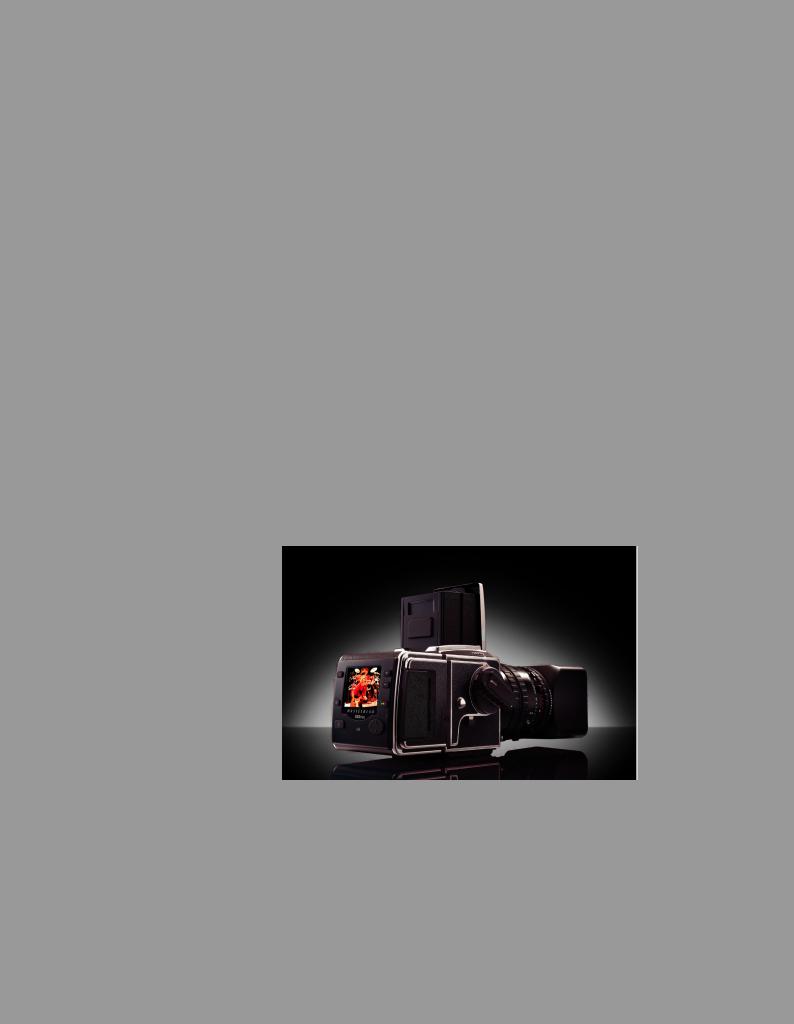
The Hasselblad 503CW is an extremely popular model from the 500 series. Soon after it was launched it became the workhorse for so many photographers, professional and amateur alike. It is an all-rounder, being as easy to use on location as in the studio.
There are many who prefer a more traditional design of camera while wishing to exploit the latest in technology and that is where the Hasselblad 503 CWD comes in. It offers the best from both worlds, mechanical and electronic. And for those who already own V-System cameras and don’t want to change, the CFV offers the chance to go digital in the most convenient and economical manner.
Hasselblad is the choice of the world’s leading photographers, and the name is synonymous with compatibility, reliability and image quality, reaching beyond the ends of the earth and into space. Congratulations, therefore, on a wise choice.
The System
The Hasselblad V-System is the most comprehensive medium-format photographic system in the world. It offers magazines for different image formats and films, viewfinders with or without exposure metering capabilities, a number of focusing screens plus a range of lenses..
The Camera
The completely mechanical camera body boasts a one-piece aluminium alloy construction to meet professional demands. The Winder CW, specifically designed for the 503CW models, provides fast sequential photography and various choices of remote control, including IR.
Altogether, a winning combination for professional or dedicated amateur use.
The Lenses
You have access to the whole range of Hasselblad ‘C’ series lenses both old and new. Lenses are specially manufactured for Hasselblad by Carl Zeiss of Germany − the indisputable leader in camera optics. The Hasselblad specifications of these lenses exceed the demands made by digital capture to ensure the optimum in performance whatever the chosen medium. The integral shutter feature combines with the TTL/OTF facility to provide tremendous flash freedom.
The CFV digital backs
The digital backs are custom built to fit the design and functionality of Hasselblad V-System cameras. However, they can also fit onto view cameras using the V-System interface plate for mechanical attachment and flash sync connection to trigger the digital capture for optimum compatibility and economy. They provide both cable free and computer tethered options to suit all types of work. The units offer an ultra high level of integration, two capture formats, image quality and flexibility to the specialist professional photographer or high-end amateur user.
“Instant” user interface
The 503CWD and CFV are operated with a straightforward user interface with a series of “instant” one-button-click operations including: instant capture, instant browse, instant approval, instant zoom, and instant image info.
Three modes of operation and storage
Optimum portability and image storage are critical for the professional photographer. The 503CWD and CFV offer a choice of portable CF card storage or tethered operation with
extended, special capture controls. With these operating and storage options, the photographer is able to select a mode to suit the nature of the work at hand, whether in the studio or on location.
4
Phocus
Phocus offers an image processing workflow with the highest degree of control. In tethered operation, tools like overlay masking help bring productivity to advanced set composition. Phocus processes the raw 3FR files generated by the Hasselblad 503CWD and CFV. It runs natively on both Macintosh and Windows platforms and is licensed to allow you to provide free copies for all your co-workers and production partners.
3FR format
In order to incorporate the unique HNCS feature we have developed a custom Hasselblad raw file format called 3F RAW (3FR). The new 3FR file format is designed to ensure that images captured on Hasselblad digital products are quickly, effectively and safely stored on the available media. This file format includes lossless image compression, which reduces the required storage space by 33%. The 3FR file defines the colors in the Hasselblad RBG color space with its out-of-the-box quality, and used in conjunction with Phocus it removes both the need for experimenting with different color profiles to obtain optimal colors and the need for selective color corrections.
Unique Hasselblad Natural Color Solution
In the past, color management solutions have imposed limitations on professional digital photographers, because of the need to choose a specific color profile to suit a specific job in order to capture various skin tones, metals, fabrics, flowers, etc. Hasselblad has helped solve this dilemma, with the development of a single powerful color profile to be used with its Phocus imaging software. Working with the new Hasselblad Natural Color Solution (HNCS) enables you to produce outstanding and reliable out-of-the-box colors, with skin tones, specific product colors and other difficult tones reproduced easily and effectively.
DAC
Images captured with a CFV and Carl Zeiss C series lenses can claim the tremendous benefits of DAC. This feature, incorporated in Phocus, makes lens model-specific corrections to ensure the ultimate image quality.
Instant Approval Architecture
Limitless digital image capture loses some of its potential if the photographer cannot quickly review and select the best images to present to the client. Building on the success of its Audio Exposure Feedback technology, Hasselblad has created Instant Approval Architecture (IAA), an enhanced set of feedback tools, designed to liberate the photographer to focus on the shoot rather than the selection process. IAA triggers audible and visual signals for each image captured, notifying the photographer immediately of its classification status. The information is recorded both in the file and in the file name, providing a quick and easy way to classify and select images, in the field or in the lab. The Hasselblad Instant Approval Architecture brings automated image classification into your digital workflow from the split-second of capture. IAA is a Hasselblad trademark and Hasselblad has a patent pending on the invention. Large enhanced display screens on the new Hasselblad products provide a realistic, high quality and perfect contrast image view, even in bright sunlight, to allow instant on-site image approval.
Your new Hasselblad camera provides access to the Hasselblad potential. The realization of this potential is only dependant upon your skill, care and judgement as a photographer. We wish you great success and welcome you to Hasselblad, the most comprehensive mediumformat system in the world.
The supreme Hasselblad potential is there, it’s up to you to exploit it!
5

1
General
Information
Photo: Joao Carlos / Hasselblad Masters
6
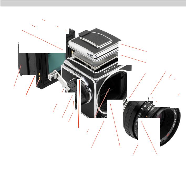
Parts & Components
1
2
3
|
|
|
|
|
|
|
|
|
|
|
|
|
|
|
|
|
|
|
|
|
|
|
|
|
|
|
|
|
|
|
|
|
|
|
|
|
|
|
|
|
|
|
|
27 |
|
24 |
|
|
|
||||||||||||
|
|
|
|
|
|
|
|
|
|
|
|
|
|
|
|
|
|
|
|
|
|
|
|
|
|
|
|
|
|
|
|
|
|
|
|
|
|
|
|
|
|
|
|
|
|
|
|||||||||||||||
|
|
|
|
|
|
|
|
|
|
|
|
|
|
|
|
|
|
|
|
|
|
|
|
|
|
|
|
|
|
|
|
|
|
|
|
|
|
|
|
|
|
|
|
|
|
|
|||||||||||||||
|
|
|
|
|
|
|
|
|
|
|
|
|
|
|
|
|
|
|
|
|
|
|
|
|
|
|
|
|
|
|
|
|
|
|
|
|
|
|
|
|
|
|
26 |
|
|
|
|
|
|||||||||||||
|
|
|
|
|
|
|
|
|
|
|
|
|
|
|
|
|
|
|
|
|
|
|
|
|
|
|
|
|
|
|
|
|
|
|
|
|
|
|
|
|
|
|
|
|
|||||||||||||||||
|
|
|
|
|
|
|
|
|
|
|
|
|
|
|
|
|
|
|
|
|
|
|
|
|
|
|
|
|
|
|
|
|
|
|
|
|
|
|
|
|
|
|
|
|
|
|
|
||||||||||||||
|
|
|
|
|
|
|
|
|
|
|
|
|
|
|
|
|
|
|
|
|
|
|
|
|
|
|
|
|
|
|
|
|
|
|
|
|
|
|
|
|
|
25 |
|
|
|
|
|
|
|||||||||||||
|
|
|
|
|
|
|
|
|
|
|
|
|
|
|
|
|
|
|
|
|
|
|
|
|
|
|
|
|
|
|
|
|
|
|
|
|
|
|
|
|
|
|
|
|
|
|
|
22 |
20 |
|
|||||||||||
|
|
|
|
|
|
|
|
|
|
|
|
|
|
|
|
|
|
|
|
|
|
|
|
|
|
|
|
|
|
|
|
|
|
|
|
|
|
|
|
|
|
|
|
|
|
|
|
|
|
|
|
||||||||||
|
|
|
|
|
|
|
|
|
|
|
|
|
|
|
|
|
|
|
|
|
|
|
|
|
|
|
|
|
|
|
|
|
|
|
|
|
|
|
|
|
|
|
|
|
|
|
|
|
|
|
|
|
23 |
21 |
|
|
|||||
|
|
|
|
|
|
|
|
|
|
|
|
|
|
|
|
|
|
|
|
|
|
|
|
|
|
|
|
|
|
|
|
|
|
|
|
|
|
|
|
|
|
|
|
|
|
|
|
|
|
|
|
|
|
|
|||||||
|
|
|
|
|
|
|
|
|
|
|
|
|
|
|
|
|
|
|
|
|
|
|
|
|
|
|
|
|
|
|
|
|
|
|
|
|
|
|
|
|
|
|
|
|
|
|
|
|
|
|
|
19 |
|
|
|||||||
|
|
|
|
|
|
|
|
|
|
|
|
|
|
|
|
|
|
|
|
|
|
|
|
|
|
|
|
|
|
|
|
|
|
|
|
|
|
|
|
|
|
|
|
|
|
|
|
|
|
|
|
|
|
|
|||||||
|
|
|
|
|
|
|
|
|
|
|
|
|
|
|
|
|
|
|
|
|
|
|
|
|
|
|
|
|
|
|
|
|
|
|
|
|
|
|
|
|
|
|
|
|
|
|
|
|
|
|
|
|
|
|
|
|
|||||
|
|
|
|
|
|
|
|
|
|
|
|
|
|
|
|
|
|
|
|
|
|
|
|
|
|
|
|
|
|
|
|
|
|
|
|
|
|
|
|
|
|
|
|
|
|
|
|
|
|
|
|
|
|
|
|
|
|
||||
|
|
|
4 |
|
|
5 |
|
6 |
|
|
|
|
|
|
|
|
|
|
|
|
|
|
|
|
|
|
|
|
|
|
|
|
|
|
|
|
|
|
|
|
|
|
|
|
|
|
|
|
|
|
|
|
|
|
|
|
|
|
18 |
||
|
|
|
|
|
|
|
|
|
|
7 |
|
8 |
|
|
|
|
|
|
|
|
|
|
|
|
|
|
|
|
|
|
|
|
|
|
|
|
|
|
|
|
|
|
|
|
|
|
|
|
|
|
|
|
|
|
|
||||||
|
|
|
|
|
|
|
|
|
|
|
|
|
|
|
|
|
|
|
|
|
|
|
|
|
|
|
|
|
|
|
|
|
|
|
|
|
|
|
|
|
|
|
|
|
|
|
|
|
|
|
|
|
|
||||||||
|
|
|
|
|
|
|
|
|
|
|
|
|
|
|
|
|
|
|
|
|
|
|
|
|
|
|
|
|
|
|
|
|
|
|
|
|
|
|
|
|
|
|
|
|
|
|
|
|
|
|
|
|
|
|
|
|
|||||
|
|
|
|
|
|
|
|
|
|
|
|
|
|
|
|
|
|
|
|
|
|
|
|
|
|
|
|
|
|
|
|
|
|
|
|
|
|
|
|
|
|
|
|
|
|
|
|
|
|
|
|
|
|
|
|
|
|||||
|
|
|
|
|
|
|
|
|
|
|
|
|
|
|
|
|
|
|
|
|
|
|
|
|
|
|
|
|
|
|
|
|
|
|
|
|
|
|
|
|
|
|
|
|
|
|
|
|
|
|
|
|
|
|
|||||||
|
|
|
|
|
|
|
|
|
|
|
|
|
|
|
|
|
|
|
|
|
|
|
|
|
|
|
|
|
|
|
|
|
|
|
|
|
|
|
|
|
|
|
|
|
|
|
|
|
|
|
|
|
|
|
|||||||
|
|
|
|
|
|
|
|
|
|
|
|
|
|
|
|
|
|
|
|
|
|
|
|
|
|
|
|
|
|
|
|
|
|
|
|
|
|
|
|
|
|
|
|
|
|
|
|
|
|
|
|
|
|
|
|||||||
|
|
|
|
|
|
|
|
|
|
|
|
|
|
|
|
|
|
|
|
|
|
|
|
|
|
|
|
|
|
|
|
|
|
|
|
|
|
|
|
|
|
|
|
|
|
|
|
|
|
|
|
|
|
|
|
|
|||||
|
|
|
|
|
|
|
|
|
|
|
|
|
|
|
|
|
|
|
|
|
|
|
|
|
|
|
|
|
|
|
|
|
|
|
|
|
|
|
|
|
|
|
|
|
|
|
|
|
|
|
|
|
|
|
|
|
|
|
|||
|
|
|
|
|
|
|
|
|
|
|
|
|
|
|
|
|
|
|
|
|
|
|
|
|
|
|
|
|
|
|
|
|
|
|
|
|
|
|
|
|
|
|
|
|
|
|
|
|
|
|
|
|
|
|
|
|
|||||
|
|
|
|
|
|
|
|
|
|
|
|
|
|
|
|
|
|
|
|
|
|
|
|
|
|
|
|
|
|
|
|
|
|
|
|
|
|
|
|
|
|
|
|
|
|
|
|
|
|
|
|
|
|
|
|
|
|
|
|
||
|
|
|
|
|
|
|
|
|
|
|
|
|
|
|
|
|
|
|
|
|
|
|
|
|
|
|
|
|
|
|
|
|
|
|
|
|
|
|
|
|
|
|
|
|
|
|
|
|
|
|
|
|
|
|
|
|
|
|
|
||
|
|
|
|
|
|
|
|
|
|
|
|
|
|
|
|
|
|
|
|
|
|
|
|
|
|
|
|
|
|
|
|
|
|
|
|
|
|
|
|
|
|
|
|
|
|
|
|
|
|
|
|
|
|
|
|
|
|
|
|
||
|
|
|
|
|
|
|
|
|
|
|
|
|
|
|
|
|
|
|
|
|
|
|
|
|
|
|
|
|
|
|
|
|
|
|
|
|
|
|
|
|
|
|
|
|
|
|
|
|
|
|
|
|
|
|
|
|
|
|
|
||
|
|
|
|
|
|
|
|
|
|
|
|
|
|
|
|
|
|
|
|
|
|
|
|
|
|
|
|
|
|
|
|
|
|
|
|
|
|
|
|
|
|
|
|
|
|
|
|
|
|
|
|
|
|
|
|
|
|
|
|
|
|
|
|
|
|
|
|
|
|
|
|
|
|
|
|
|
|
|
|
|
|
|
|
|
|
|
|
|
|
|
|
|
|
|
|
|
|
|
|
|
|
|
|
|
|
|
|
|
|
|
|
|
|
|
|
|
|
|
|
|
|
|
|
|
|
|
|
|
|
|
|
|
|
|
|
|
|
|
|
|
|
|
|
|
|
|
|
|
|
|
|
|
|
|
|
|
|
|
|
|
|
|
|
|
|
|
|
|
|
|
|
|
|
|
|
|
|
|
|
|
|
|
|
|
|
|
|
|
|
|
|
|
|
|
|
|
|
|
9 |
|
|
|
10 |
|
11 |
|
12 |
|
|
|
|
|
|
|
|
|
|
|
|
|
|
|
|
|
|
|
|
|
|
|
|
|
|
|
|
|
|
|
|
|
|
|
|||||
|
|
|
|
|
|
|
|
|
|
|
|
|
|
|
|
|
|
|
|
|
|
|
|
|
|
|
|
|
|
|
|
|
|
|
|
|
|
|
|
|
|
|
|
|
|
|
|
|
|
|
|
|
|
|
|
|
|
|
|||
|
|
|
|
|
|
|
|
|
|
|
|
|
|
|
|
|
|
|
|
|
|
|
|
|
|
|
|
|
|
|
|
|
|
|
|
|
|
|
|
|
|
|
|
|
|
|
|
|
|
|
|
|
|
|
|
|
|
|
|
||
|
|
|
|
|
|
|
|
|
|
|
|
|
|
|
|
|
|
|
|
|
|
|
|
|
|
|
|
|
|
|
|
|
|
|
|
|
|
|
|
|
|
|
|
|
|
|
|
|
|
|
|
|
|
|
|
|
|
|
|||
|
|
|
|
|
|
|
|
|
|
|
|
|
|
|
|
|
|
|
|
|
|
|
|
|
|
|
|
|
|
|
|
|
|
|
|
|
|
|
|
|
|
|
|
|
|
|
|
|
|
|
|
|
|
|
|
|
|
|
|
|
|
|
|
|
|
|
|
|
|
|
|
|
|
|
|
|
|
|
|
|
|
|
|
|
|
|
|
|
|
|
|
|
|
|
|
|
|
|
|
|
|
|
|
|
|
|
|
|
|
|
|
|
|
|
|
|
|
||||||
|
|
|
|
|
|
|
|
|
|
|
|
|
|
|
|
|
|
|
|
|
|
|
|
|
|
|
|
|
|
|
|
|
|
|
|
|
|
|
|
|
|
|
|
|
|
|
|
|
|
|
|
|
|
|
|
||||||
|
|
|
|
|
|
|
|
|
|
|
|
|
|
|
|
|
|
|
14 |
|
|
|
|
|
|
|
|
|
|
|
|
|
|
|
|
|
|
|
|
|
|
|
|
|
|
||||||||||||||||
|
|
|
|
|
|
|
|
|
|
|
|
|
|
13 |
|
|
|
|
|
|
15 |
|
|
16 |
|
|
|
|
|
|
|
|
|
|
|
|
|
|
|
||||||||||||||||||||||
|
|
|
|
|
|
|
|
|
|
|
|
|
|
|
|
|
|
|
|
|
|
|
|
|
|
|
|
|
|
|
|
|
|
|
|
|
|
|
|
|
|
|
|
|
|
|
|
|
|
|
|||||||||||
|
|
|
|
|
|
|
|
|
|
|
|
|
|
|
|
|
|
|
|
|
|
|
|
|
|
|
|
|
|
|
|
|
|
|
|
|
|
|
|
|
|
17 |
|
|
|
|
|
|
|
|
|
|
|||||||||
|
|
|
|
|
|
|
|
|
|
|
|
|
|
|
|
|
|
|
|
|
|
|
|
|
|
|
|
|
|
|
|
|
|
|
|
|
|
|
|
|
|
|
|
|
|
|
|
|
|
|
|
|
|
|
|
|
|
|
|
|
|
|
|
|
|
|
|
|
|
|
|
|
|
|
|
|
|
|
|
|
|
|
|
|
|
|
|
|
|
|
|
|
|
|
|
|
|
|
|
|
|
|
|
|
|
|
|
|
|
|
|
|
|
|
|
|
|
|
|
|
|
|
|
1. |
Lock safety button |
14. |
Drive shaft |
|
|
|
|
|
|
|
|
|
|
|
|
|
|
|
|
|
|
|
|
|
|||||||||||||||||||||||||||||||||||||
2. |
Lock button |
|
|
|
|
|
|
|
|
|
|
|
|
|
|
|
|
|
|
|
15. |
Exposure value index |
|
|
|
|
|
|
|
|
|
|
|
|
|
|
|
|
|
|
|
|
|
||||||||||||||||||
3. |
Sensor (covered by glass IR filter) |
16. |
Exposure value scale |
|
|
|
|
|
|
|
|
|
|
|
|
|
|
|
|
|
|
|
|
|
|||||||||||||||||||||||||||||||||||||
4. |
CF card cover |
|
|
|
|
|
|
|
|
|
|
|
|
|
|
|
|
|
|
|
17. |
Shutter speed and aperture interlock button |
|
|
|
|
|
|
|
||||||||||||||||||||||||||||||||
5. |
Sync socket (for use with Winder CW and EL-type cameras) |
18. |
External and internal lens accessory mount |
|
|
|
|
|
|
|
|||||||||||||||||||||||||||||||||||||||||||||||||||
6. |
Databus contacts |
19. |
PC flash/strobe terminal |
|
|
|
|
|
|
|
|
|
|
|
|
|
|
|
|
|
|
|
|
|
|||||||||||||||||||||||||||||||||||||
7. |
Strap lug |
|
|
|
|
|
|
|
|
|
|
|
|
|
|
|
|
|
|
|
20. |
Shutter speed ring |
|
|
|
|
|
|
|
|
|
|
|
|
|
|
|
|
|
|
|
|
|
||||||||||||||||||
8. |
Winding crank |
|
|
|
|
|
|
|
|
|
|
|
|
|
|
|
|
|
|
|
21. |
Aperture ring and scale |
|
|
|
|
|
|
|
|
|
|
|
|
|
|
|
|
|
|
|
|
|
||||||||||||||||||
9. |
Pre-release button |
22. Depth-of-field scale |
|
|
|
|
|
|
|
|
|
|
|
|
|
|
|
|
|
|
|
|
|
||||||||||||||||||||||||||||||||||||||
10. |
Winding crank index |
23. |
Central lens index |
|
|
|
|
|
|
|
|
|
|
|
|
|
|
|
|
|
|
|
|
|
|||||||||||||||||||||||||||||||||||||
11. |
Viewfinder mirror |
24. |
Focusing ring and scale |
|
|
|
|
|
|
|
|
|
|
|
|
|
|
|
|
|
|
|
|
|
|||||||||||||||||||||||||||||||||||||
12. |
Shutter release button |
25. |
Lens release button |
|
|
|
|
|
|
|
|
|
|
|
|
|
|
|
|
|
|
|
|
|
|||||||||||||||||||||||||||||||||||||
13. |
Threaded cable release socket |
26. |
Focusing screen: Acute-Matte D screen |
|
|
|
|
|
|
|
|
|
|
|
|
|
|
|
|||||||||||||||||||||||||||||||||||||||||||
|
|
|
|
|
|
|
|
|
|
|
|
|
|
|
|
|
|
|
|
|
|
|
|
|
|
|
27. |
Focusing hood |
|
|
|
|
|
|
|
|
|
|
|
|
|
|
|
|
|
|
|
|
|
||||||||||||
7
59 |
57 |
|
|
|
|
|
58 |
56 |
55 |
54 |
53 |
52 |
51 |
|
|
|
|
|
|
50 |
28 |
|
|
|
|
|
49 |
|
|
|
|
|
|
|
29 |
|
|
|
|
|
|
30
31
32
33
34
35
48
47
46
|
|
36 |
37 |
38 |
39 |
40 |
41 |
42 |
43 |
44 |
45 |
28. Focusing hood magnifier |
|
|
|
44. Battery contacts |
|
|
|
|
|
||
29. |
Magazine hook |
|
|
|
45. |
Battery (not supplied) |
|
|
|
|
|
30. |
Auxiliary shutter |
|
|
|
46. Ready light indicator |
|
|
|
|
|
|
31. |
Film speed selector |
|
|
|
47. |
Navigation button |
|
|
|
|
|
32. |
Strap lug |
|
|
48. Busy light indicator |
|
|
|
|
|
||
33. |
Accessory rail |
|
|
49. |
Instant Approval button |
|
|
|
|
|
|
34. Lens locating index |
|
|
50. Zoom out / Value change button |
|
|
|
|||||
35. |
Dedicated flash/strobe connector |
|
|
51. |
Zoom in / Value change button |
|
|
|
|||
36. |
Lens drive shaft |
|
|
52. |
Display |
|
|
|
|
|
|
37. |
Camera support |
|
|
53. |
Display button |
|
|
|
|
|
|
38. Quick-coupling plate |
|
|
54. Menu button |
|
|
|
|
|
|||
39. |
Tripod threads, 1/4” & 3/8” |
|
|
55. |
ON / OFF button |
|
|
|
|
|
|
40. Digital back /magazine supports |
|
|
56. Flash sync OUT terminal |
|
|
|
|
|
|||
41. |
Digital back support slots |
|
|
57. |
Flash sync IN terminal |
|
|
|
|
|
|
42. |
Battery release catch |
|
|
58. Firewire 800 socket |
|
|
|
|
|
||
43. |
Battery support lugs |
|
|
59. |
Ventilator |
|
|
|
|
|
|
8

2
Camera Body
This section describes the basic operations. Follow the instructions step-by-step to avoid damaging the equipment. Check that the winding crank on the right hand side of the camera is locked thus ensuring that the camera is fully wound. If the crank is not locked, rotate it clockwise until it does lock, thereby winding the camera.
Photo: Bang Peng / Hasselblad Masters
9
1 |
3 |
4 |
5 |
Front protective cover |
1 |
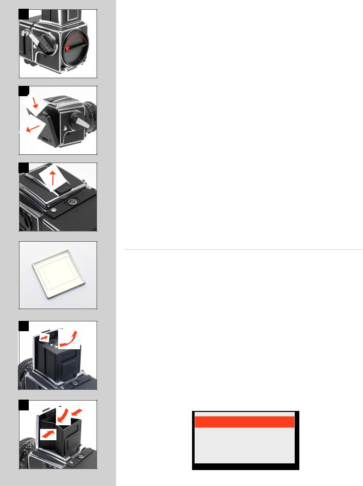
Always fit the front protective cover when no lens is attached to protect the mirror and interior.
Attach the cover as you would a lens, see below. To remove, turn the cover (bayonet fitting) in the direction of the arrow and lift it out.
Rear cover MultiControl |
2 |
Always fit the rear cover MultiControl when no back is attached to protect the auxiliary shutter. Attach the cover as you would a back, see below.
To remove, depress the top part, tilt the cover backwards, and lift it off. See later sections on the other uses of the Rear cover MultiControl.
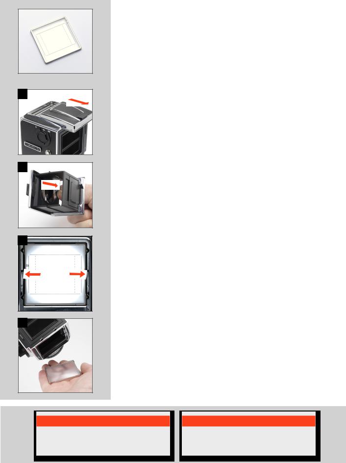
Opening the focusing hood |
3 |
Lift the lid by firmly gripping the tab on its rear edge, and swinging it up to a vertical position. The hood unfolds automatically and locks in the open position.
Built-in magnifier |
4 |
The magnifier flips up into the viewing position when the oval button inside the lid is moved to the right, as in the illustration. To fold the magnifier down simply press it back down towards the lid until it locks into place. It can easily be exchanged to suit individual eyesight (see “Changing the magnifier”).
Focusing screen and viewfinder image
The 503CW/503CWD is fitted with an Acute-Matte D focusing screen for unrivalled brightness and sharpness. The markings on the screen indicate the format of the sensor in the case of the 503CWD for correct composition with digital capture. The screen can easily be exchanged for others specially designed for various applications (see “Changing the focusing screen”).
Closing the focusing hood |
5 |
Fold away the magnifier by pressing it back down towards the lid until it locks into place. ‘Pinch’ in the side plates at the hinge points and then push the lid lightly backwards. The hood then automatically folds back down.
N ote
The front protective cover can only be removed when the camera is fully wound.
10
6
8 |
9 |
10 |
11 |
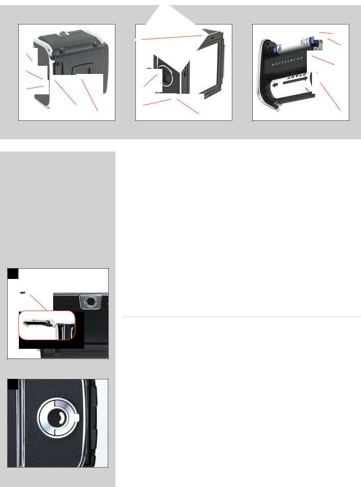
Winding crank |
6, 7 |
The winding crank can be removed. Push the catch lever downwards while rotating the crank counter-clockwise and pull the crank straight out from the shaft. To attach it, align the small triangular index mark against the red dot on the camera body. Keep the crank pushed against the camera while turning it clockwise until the larger triangular mark is aligned with the red dot where it will click into position.
Accessory rail |
8 |
The camera has an accessory rail on the left hand side for the spirit level and the adjustable flash shoe (for small flash units).
Strap attachment and removal |
9, 10, 11 |
Place the main body of the strap clip over one of the camera’s strap lugs. Press the tip of the clip towards the camera while pulling back on the strap so that the clip slides over the lug and locks into position. To remove the strap, lift the clip locking plate high enough to be able pass over the camera lug. Slide the clip in the direction away from the strap until it is free.
11

3
Lenses
The 503CW/503CWD is compatible with lenses that have an integral leaf shutter, namely, all C series lenses. CFi/CFE lenses are the latest developments and are mentioned and illustrated here as the conventional choice. C, CF and CB lenses, although differing in specification and appearance to CFi/ CFE lenses, are operated in a very similar manner but please see the relevant instruction manuals for complete details.
Photo: Alexandfelix / Hasselblad Masters
12
1.Shutter speed ring
2.F-setting button
3.Warning mark
4.Depth-of-field preview knob
5.PC-socket with positive lock
6.Central lens index
7.Focusing distance scale
8.Lens bayonet plate with red index
9.External and internal front bayonets
10.EV index
11.Exposure value (EV) scale
12.Shutter speed/aperture interlock button
13.Shutter speed scale
14.Aperture ring and scale
15.Depth-of-field scale
16.Infrared focusing index
17.Focusing ring
|
Zeiss Planar CFE 2.8/80 mm |
1 |
9 |
2 |
10 |
3 |
11 |
4 |
12 |
5 |
13 |
6 |
14 |
|
7 |
15 |
|
16 |
||
8 |
||
17 |
The illustrations show the CFE version of the 2.8/80 mm lens but the layout of the parts is identical on all CFi /CFE lenses.
1
2 |
3 |
Shutter speed and aperture |
1 |
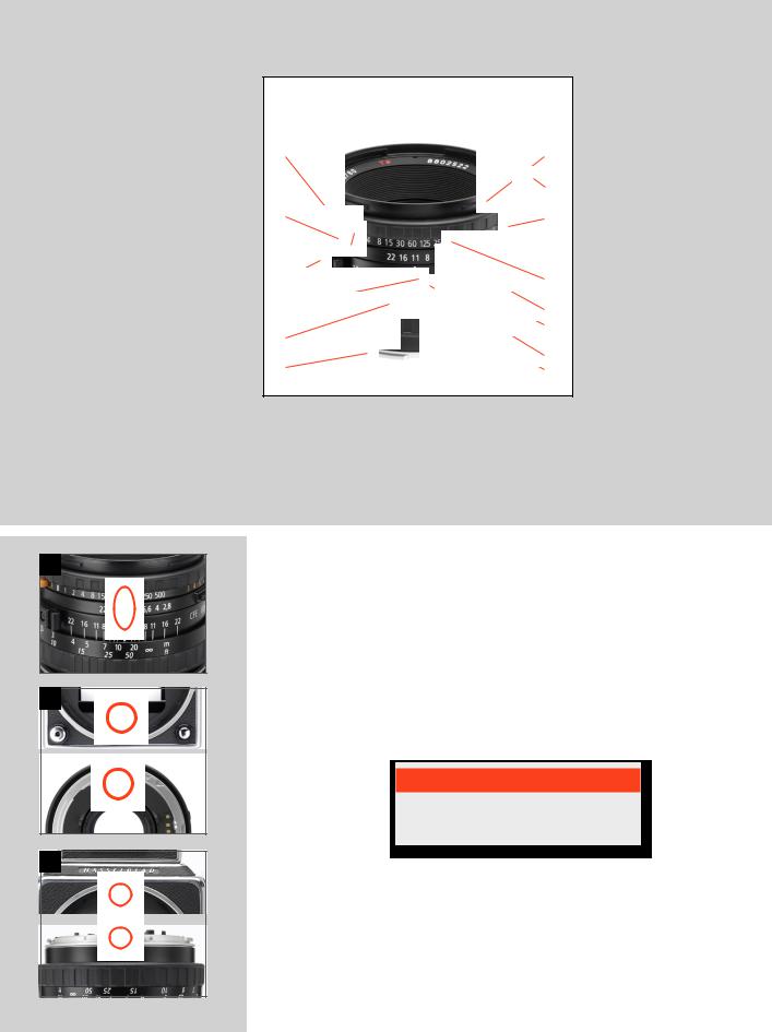
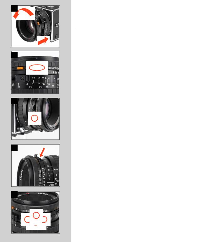
The shutter speed selector ring is the ring located closest to the front of the lens. To set the speed, turn the ring until the desired marked shutter speed position aligns with the central lens index. The white scale shows the shutter speeds, and the orange scale the exposure values (EV). The aperture setting ring is the second closest ring to the front of the lens. The aperture value is also set against the central lens index. The diaphragm is automatic and stops down to the preset working aperture at the start of the exposure sequence. Therefore in the illustration, the exposure setting is 1/60 second at f/11.
The orange ‘F’ setting is used only when the lens is attached to a Hasselblad camera in the 200 or 2000 series with a focal plane shutter. The operation of the diaphragm is not affected. The ‘F’ setting can only be engaged/disengaged when the orange lever is pressed.
N ote
If the F setting is used, exposure errors will occur because the shutter remains open.
Attaching the lens |
2, 3 |
Make sure that both camera and lens are fully wound. Illustration 2 shows the correct relationship between the drive shaft, the lens drive coupling and their indexes. If the lens is not wound, you can insert a small coin or similar in the coupling slot and rotate it clockwise until it locks (about 4/5 of a turn) When you have aligned the red index on the lens with the one on the camera (illus 3), the lens will drop easily into the bayonet fitting. You can then rotate it clockwise until it stops with a faint click as the lens catch locks it in place.
13
4 |
5 |
6
7
8 |
Removing the lens |
4 |
Depress the lens release button and rotate the lens counter-clockwise until it stops and lift it out of the mount.
Exposure
As a general rule for all shutter speed settings except B, you should keep the release button depressed until the lens shutter has opened and closed fully. This is especially important at shutter speeds from Is to l/4s, as the auxiliary shutter remains open only when the button is kept depressed (see also ‘Warning Mark’ below). If you remove the magazine, you can see the auxiliary shutter, consisting of two blinds, covering the rear opening of the camera body. It protects the film from unwanted exposure as the lens” shutter normally is open for focusing.
Warning mark |
5 |
You will find an orangeline on the shutter speed scale above the 1, 1/2, and l/4s settings. This is to warn you of possible exposure errors as detailed above. The auxiliary shutter will terminate the exposure prematurely if you relax the pressure on the button too soon. Listen to the buzzing sound of the delay escapement in the lens’ shutter and maintain the pressure on the release button until the sound stops.
Exposure values |
6 |
The aperture and shutter speed combination set opposite the central lens index determines the exposure. Every combination of shutter speed / aperture has an equivalent exposure value (EV) which you can read and set against the red EV index on the right hand side of the lens.
Interlocked shutter speed /aperture |
7 |
If you want to change the shutter speed or aperture while still keeping the same shutter speed/aperture combination (EV), you can interlock the speed and aperture setting rings by holding down the interlock button which is on the right of the aperture scale. When interlocked, the rings move together, increasing or decreasing the aperture to compensate for a decrease or increase of speed respectively.
Focusing and depth of field |
8 |
The focusing ring is closest to the camera body. It has a knurled rubber grip and engraved distance scales in feet and metres. Focus the lens by rotating the focusing ring until you obtain a sharp image of the subject in the viewfinder. The distance between the subject and the film plane is read off the focusing ring’s distance scale opposite the central lens index. Objects closer or further away than the selected distance will be sharp, within certain limits. The limits of this field of sharp focus-depth of field-vary with the aperture. The depth of field available at any given aperture can be read off the depth of field scale on both sides of the central index. As an example, the illustration indicates how to read the depth of field scale at an aperture of f/11. The depth of field will in this case range from ca 6 metres to infinity.
|
|
|
|
|
|
|
|
|
|
|
|
|
|
|
|
|
|
|
|
|
|
Note |
|
|
Note |
|
Note |
|
|
|
|
|
|
|
|
|
|||
|
|
You can only remove a lens |
|
|
For exposure times longer than 1/8 sec when shooting digitally, |
|
See section ‘Film Magazines’ |
|
|
|
|
when the camera is fully |
|
|
connect the Flash sync input cable (supplied) between the PC- |
|
for information about using |
|
|
|
|
wound and not In the pre- |
|
|
socket (flash/strobe sync contact) on the lens and the Flash sync |
|
infrared film. |
|
|
|
|
released mode (see “Pre- |
|
|
IN terminal on the CFV. This eliminates any conflict between the |
|
|
|
|
|
|
release and cable release). |
|
|
shutter setting and the CFV ‘time -out‘ setting. |
|
|
|
|
|
|
|
|
|
|
|
|
|
|
|
|
|
|
|
|
|
|
|
|
14

9 |
10 |
11 |
Depth of field preview |
9 |
Depth-of-field can be visually checked on the focusing screen. The diaphragm can be stopped down to the preset aperture from its normally wide open position simply by pushing the depth-of-field preview lever downwards until it locks. To reopen the diaphragm, depress the lower part of the lever.
Pre-release and cable release |
10 |
Considerable efforts have been made to reduce camera vibrations caused by moving parts in the exposure sequence. However, if you wish to avoid these vibrations completely, you can pre-release the mechanism by pushing the pre-release button upwards. This causes the following sequence:
1.The mirror folds up
2.The shutter closes and remains closed
3.The diaphragm closes to its preset aperture
4.The auxiliary shutter opens
When you subsequently press the release button, only the shutter then operates at the preset speed. As shown in the illustration, you can also attach a cable release to further reduce vibrations.
Flash/strobe synchronization |
11 |
The C series lenses have built-in leaf shutters with speeds from 1s to 1/500s and B. Flash synchronization occurs at full shutter opening via the PC flash/strobe terminal. Suitable electronic flash/strobe units can be used at all shutter speeds from 1s to 1/500s as well as B. Please see under ‘Flash’ the sections on the use of a Hasselblad Flash adapter SCA 390.
15
4
Viewfinder System
The 503CW/503CWD is supplied with a light, compact and foldable viewfinder, providing a through-the-lens laterally reversed image. It is easily interchangeable with alternative viewfinders including the prism finders, which produce a laterally corrected image. Please see ‘Accessories’ for further details about prism finders.
Photo: Lyle Owerko / Hasselblad Masters
16
Sensor format markings on the “36x49” screen.
1 |
2 |
3 |
4 |
The focusing hood on the standard viewfinder has a built-in 4.5x magnifier for accurate focusing and this can easily be changed to suit individual eyesight. The 503CW is equipped with an AcuteMatte D focusing screen which produces an exceptionally bright and sharp image. The markings indicate the format of the sensor for correct composition with digital capture. The Hasselblad system offers a range of alternative screens for various specific applications, each item easily and quickly interchangeable without the need for special tools or facilities.
Changing the focusing hood or viewfinder |
1 |
To remove the focusing hood so as to attach any other viewfinder in the present Hasselblad system (please note the PM90 is compatible with film magazines only due to its shape),
proceed as follows:
1.Detach the digital back.
2.Fold down the focusing hood to protect it from damage and remove it by sliding it to the rear in its guide slots.
3.Slide the replacement viewfinder into the slots and push it forward until it stops.
When fully inserted the viewfinder is retained in position by a spring-loaded catch until you have reattached the magazine.
Changing the magnifier |
2 |
Mounted lenses with dioptre correction from +3 to -4 are available, and are easily interchanged as follows:
1.Remove the focusing hood from the camera and open it by lifting the lid.
2.Release the magnifier by pushing the catch to the right.
3.Push the magnifier halfway back down to its folded position.
4.Grip the lower edge of the magnifier plate (through the underside of the hood), and pull firmly.
5.Keep the plate holder halfway down and insert the replacement lens plate with the printed side up. Fold the hood down and replace on the camera.
Changing the focusing screen |
3, 4 |
1.Detach the magazine and viewfinder.
2.Push the two screen clips to the side into their recesses (fig 3).
3.Place your hand over the screen, and invert the camera. The screen will now drop into your hand (fig 4).
4.Insert the replacement screen, ensuring that the smooth flat side is uppermost and the sharp-edged corners down. Ensure that all four corners of the screen are positively seated on their supports.
You need not return the screen latches. This is done automatically when the viewfinder is replaced.
Should the screen refuse to drop out by itself, ensure that the camera is fully wound, remove the lens and check that the mirror is in the down position. Put a finger through the lens mount and push gently on the screen from underneath, preferably with a soft cloth between the screen and the finger.
N ote
Do not immerse the screen in water, or use any kind of cleaning fluid.
Note
Do not use hot air to dry the screen if it becomes damp.
17

5
Film Magazines
A number of different film magazines were produced over the years to accommodate various film types and formats. The film magazine described here is the most recent and common version.
Photo: Claudio Napolitan / Hasselblad Masters
18
|
|
|
J |
|
|
|
|
K |
|
A |
|
|
L |
|
|
|
|
||
B |
|
|
M |
|
|
|
N |
||
|
|
|
||
C |
G |
|
O |
|
|
H |
|
P |
|
|
|
Q |
||
D |
E |
I |
||
|
1
2
‘A12’ film magazines accept all 120 size films and produce a 6 x 6cm image. They are easy to use and can be pre-loaded for rapid workflow. They provide the opportunity to vary the type of film used and can be quickly and easily switched mid-film without losing any frames.
There are a number of reasons why using film might either be preferable or even necessary for digital photographers too. For example you might want the specific results you know that a certain film emulsion can produce or you might want to use very long exposure times, etc.
A magazine also functions as an emergency battery-free back up to a digital back. Also, remember that a 6 x 6 cm film magazine use will also allow you to exploit the full focal length of your lenses.
Operation of the magazines is not difficult but pay particular attention to the section on loading. Go through the procedure one step at a time and practice a little until you feel confident. Note especially which way round the spool of film is placed and the positioning of the backing paper under the clamp bar.
The film is automatically advanced frame-by-frame in the magazine by the camera winding mechanism and consequently only when attached to the camera body. Therefore when separated, the magazine and camera body could become unmatched. This can be determined by checking the magazine status indicator or by the winding crank status.
Parts & components
A. |
Magazine slide |
J. |
Film take-up spool |
B. |
Magazine status indicator |
K. |
Grooved take-up knob |
C. |
Film holder key |
L. |
Film clamp |
D. |
Magazine slide holder |
M. |
Film holder number |
E. |
Film tab holder |
N. |
Spool clamp bar |
F. |
Lock button |
0. |
Film supply spool |
G. |
Film winder crank |
P. |
Film load index |
H. |
Frame counter |
Q. |
Film load index for Ilford black & white film only |
I. |
Film advance indicator |
|
|
Attaching the magazine |
|
1, 2, 3 |
|
Ensure that the magazine slide is fully inserted with the hinge towards the front of the camera (fig 1) and that the magazine status indicator is white (fig 2). If the indicator is red then see “Magazine status indicator” below. It is also advisable to have the camera fully wound.
Rest the magazine on the magazine supports making sure that the lugs (A) are properly engaged in the recesses (B) (fig 3). Carefully swing the magazine towards the camera body and check that the camera’s upper support hooks (C) fit into the slots (D) in the magazine.
Push the magazine gently but firmly against the hooks (fig 3) while sliding the lock button
19

(A) to the right. Release the button when the magazine has made 3 contact with the camera body, and then push the button to the left to ensure that it has reached the locked position. Remove the slide
to positively lock the magazine to the camera body.
|
D |
D |
|
|
C |
|
C |
|
|
Removing the magazine |
|
|
|
|
|
|
|
|
|
|
|||||
|
|
|
|
|
|
|
|
|
|
|
Removing the magazine is simply the reverse of the attaching |
|
|
|
|
|
|
|
|
|
|
|
|
procedure. It is advisable to have the camera fully wound and the |
|
|
|
B |
|
|
|
|
|
|
|
|
magazine indicator displaying white (see below). |
|
|
|
|
|
|
|
|
|
|
|
Insert the magazine slide fully with the hinge towards the front of the |
||
|
|
|
|
|
|
|
|
|
|
|||
|
|
B |
|
|
A |
|
|
A |
camera. Slide the magazine catch to the right, swing the magazine |
|||
|
|
|
|
|
|
|
|
|
back and lift it off the lower supports. |
|
||
|
|
|
|
|
|
|
|
|
|
|
|
|
|
|
|
|
|
|
|
|
|
|
|
Magazine status indicator |
5 |
4 |
|
|
|
|
5 |
|
|
|
|
|||
|
|
|
|
|
|
|
|
The status indicator on the right hand side of the magazine shows |
||||
|
|
|
|
|
|
|
|
|
|
|
||
|
|
|
|
|
|
|
|
|
|
|
white when the magazine is ready to operate and red when the film |
|
|
|
|
|
|
|
|
|
|
|
|
has not been advanced after an exposure. |
|
|
|
|
|
|
|
|
|
|
|
|
If the status indicator shows red, release the camera first before |
|
|
|
|
|
|
|
|
|
|
|
|
attaching the magazine. Then, winding the camera again will auto- |
|
|
|
|
|
|
|
|
|
|
|
|
matically advance the film by one frame. |
|
Loading the magazine
1 |
|
|
2 |
|
|
|
|
|
|
3 |
|
|
4 |
|
|
|
|
|
|
5 |
|
|
6 |
|
|
|
|
|
|
7 |
|
|
8 |
|
|
|
|
|
|
The magazine can be loaded on, or off the camera. If it is to be loaded off the camera, then the magazine slide must be inserted first.
In either case, when inserting the slide ensure that its flat side is towards the rear (see detail in illustration 4) as this facilitates the removal of the film holder.
Step-by-step film loading |
1–8 |
Follow the procedure below in the correct order.
1.Fold out the film holder key.
2.Turn the key counter-clockwise and withdraw the film holder (magazine insert).
3.Place an empty take-up spool under the grooved knob of the spool clamp bar. Insert a roll of film under the other end of the bar, turned the same way as in the illustration. Be sure to remove all of the paper band surrounding a new roll of film.
4.Turn the film holder key clockwise to open the film clamp. Pull 8 -10 cm (3 - 4 in.) of paper backing off the film roll and slide the edge under the clamp.
5.Insert the tongue of the backing paper into the slot in the take-up spool.
6.Turn the grooved knob clockwise until the arrow on the paper backing is aligned opposite the triangular index (or oblong index with Ilford black & white film) on the spool clamp bar, but no further.
7.Turn the film holder key counter-clockwise and insert the film holder into the magazine. Ensure that it is correctly positioned. Turn the film holder key clockwise to lock the film holder in the magazine and then fold the key back into place.
8.Fold out the film crank and rotate it clockwise about ten turns until it stops. Then turn it counter-clockwise and fold it in. The figure (1) will now be displayed in the automatic frame-coun- ter window indicating that the magazine is loaded and ready for use.
20
11
12
Removing film from the magazine |
9 |
When the last frame has been exposed and wound on, the magazine blocks the camera for further release.
Wind off the film by folding out the film winding crank, and rotate it clockwise until you can feel the film leaving the supply spool.
You can now withdraw the film holder from the magazine and remove the exposed film.
The frame counter is automatically reset when the film holder is withdrawn from the magazine.
Film tab holder |
11 |
The end tab of the film pack can be inserted in the holder on the back of the magazine as a reminder of the kind of film that has been loaded into the magazine.
Film plane position |
12 |
In close-up photography the film-to-subject distance can be an important factor when determining an accurate focus setting.The red line in the illustration marks the location on the film magazines that coincides with the film plane position.
Double exposure with film
Double (or multiple) exposure is possible with a film magazine. However, as the camera has been designed to prevent accidental double exposure you will have to carry out the following procedure in order to make multiple exposures on the same frame:
1.Make the initial exposure.
2.Insert the magazine slide and remove the magazine.
3.Wind the camera with one full revolution of the winding crank.
4.Replace the magazine and remove the slide.
5.Make the next exposure.
6.Repeat the procedure for further exposures on the same frame.
Note
Do not attach a magazine showing white to a camera that is not rewound! Wind the camera first or you will lose a frame.
Note
The shutter cannot be operated when a magazine, with slide inserted, is attached to the camera.
Note
The magazine cannot be removed without first inserting the magazine slide.
21
14
15
16 |
Flash/strobe with film |
14, 15 |
Any flash/strobe unit can be connected to the 503 CW / 503 CWD via the PC flash/strobe terminal on the lens for manually controlled flash exposure with flash sync speeds are up to 1/500s.
Automatic flash control, or dedicated flash, is provided by the camera’s built-in flash sensor and electronics (TTL/OTF) that measure the light reflected from the central portion of the film; a circle with a diameter of 40 mm.
The metering system is connected to a selector for setting film speed. When an SCA 300 compatible flash/strobe unit is connected through an SCA390 flash/strobe adaptor, the system controls the flash/strobe unit and cuts off the flash when the exposure is correct. Under the left hand edge of the focusing screen an indicator light shows when the flash is ready to be operated and also confirms if the flash output was sufficient to give a correct exposure. The flash/strobe unit powers the camera’s electronics and also the flash/strobe adaptor, when that is used.
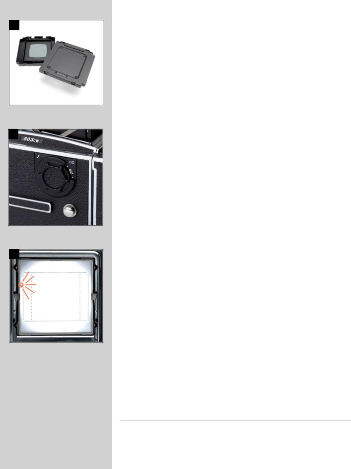
Setting the film speed for TTL/OTF flash
The film speed is set via the ISO selector. This is marked in ISO/ASA settings from 64 − 4000.
Note that certain films require compensation due to differences in reflective properties of various emulsions. In these instances, the compensation can be made by changing the film speed selector setting. The amount of compensation has to be determined by experiment. Alternatively you can replace the magazine with the Rear cover MultiControl for a few test exposures. The grey surface acts as an 18% grey card to provide a well-balanced starting point for exposures.
Please refer to your flash/strobe unit’s operating instructions for more information about other functions when using an automatic flash light-metering that conforms to System SCA flash/strobe photography with flash sensors, or with non−automatic flash/strobe units.
Viewfinder indicator |
16 |
Flash/strobe operation and flash battery–check are indicated by a red light, located under the left edge of the focusing screen. It is operative only when a dedicated flash/strobe is connected to the TTL socket. It indicates three separate states as described below.
Ready signal
A steady red light indicates that the flash/strobe unit is charged and ready to be fired. Absence of any signal indicates the need for fresh batteries.
Confirmation signal
A flashing red light occurring for just over a second immediately after exposure confirms that the light output was sufficient for a proper exposure. It then remains dark until the flash/strobe unit has recharged. The steady red light will then reappear indicating operative status again. The time of reappearance however may vary according to the condition of the batteries.
No result signal
Absence of the flashing confirmation signal after exposure indicates that the flash emitted was not sufficient for correct exposure. The aperture must then be opened more or the flash distance to the subject reduced. Changing to a faster ISO setting on the CFV is also a possibility.
See appropriate manuals for connection details regarding the various units and adapters.
Attaching a Hasselblad flash adaptor SCA 390
For use with hand-held flash/strobe units.
•The 6-pole contact from the spiral cord is connected to the camera’s dedicated flash connector.
•Thesynccord isconnected fromtheadaptor to thePCflashterminal of thelens.
•Theflash/strobe unitconnecting cord isattached to theflash/strobe unit.
22

Note
Please observe the special information that came with your IR film about restrictions concerning magazine loading, film development, etc.
Using infrared film
Infrared (IR) rays (wavelengths longer than 800 nm) form an image on a plane further away from the lens than the image plane for visible light. To compensate for this difference you have to align the chosen distance against the red IR index and not the normal central index. Proceed as follows:
1.Focus as usual on the focusing screen.
2.Note the distance on the focusing scale that is opposite the central index line.
3.Now rotate the focusing ring to set this distance opposite the dashed IR index line instead of the central index line.
General points and tips
•Before you can make an exposure, you must remove the magazine slide. The magazine will then be locked on the camera body, and the camera release button will be unblocked.
•Film is automatically advanced in the magazine after a full turn of the crank.
•You cannot remove a film magazine without re-inserting the magazine slide first.
•Do not attach a magazine showing red to a fully wound camera! This could result in a double exposure.
•Themagazine’sfilmwindingcrankisonlyblockedatframe1.Apartiallyexposedfilm may be wound off at any frame afterwards.
•On the rear of the magazine is a slide pocket where the magazine dark slide can be kept when not in use. Turn the slide with the hinge towards the rear to fold the bow fully into the slide pocket recesses.
•Do not put the film holder down on an unclean surface or where it can attract dust.
•Clean out the magazine housing regularly removing not only dust and particles but also any scraps of paper from previous rolls that may have remained inside.
•Each magazine housing and film holder form a carefully matched pair. Be careful, therefore, when loading more than one magazine at a time not to switch housings and holders. The last three figures of the housing serial number should correspond with the serial number on the film holder.
•Load and unload the magazine away from direct light sources.
•If you keep the slide inserted in an attached magazine, it will act as an exposure lock to prevent inadvertent exposures when the camera and shutter have been wound on.
•AlignthearrowonthepaperbackingofallIlfordblack&whitefilmsagainsttheoblong index (and no further) on the spool clamp bar and not the triangular index as normal.
23
6
Accessories
Some accessories are still currently available for the 503CW to expand your system and tailor it to suit your needs.
Photo: Stephan Zirwes / Hasselblad Masters
24
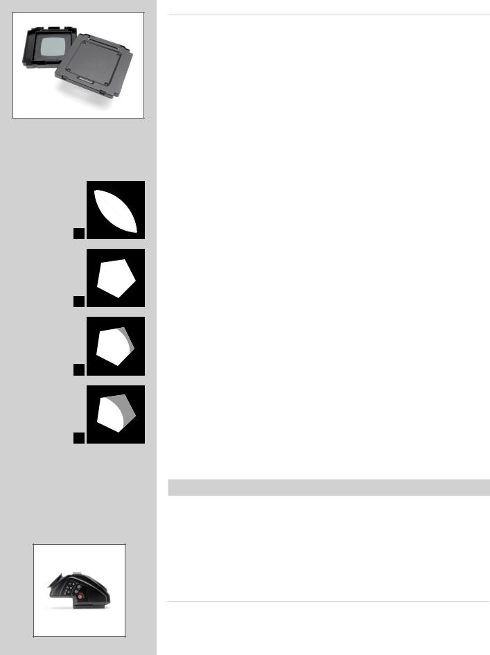
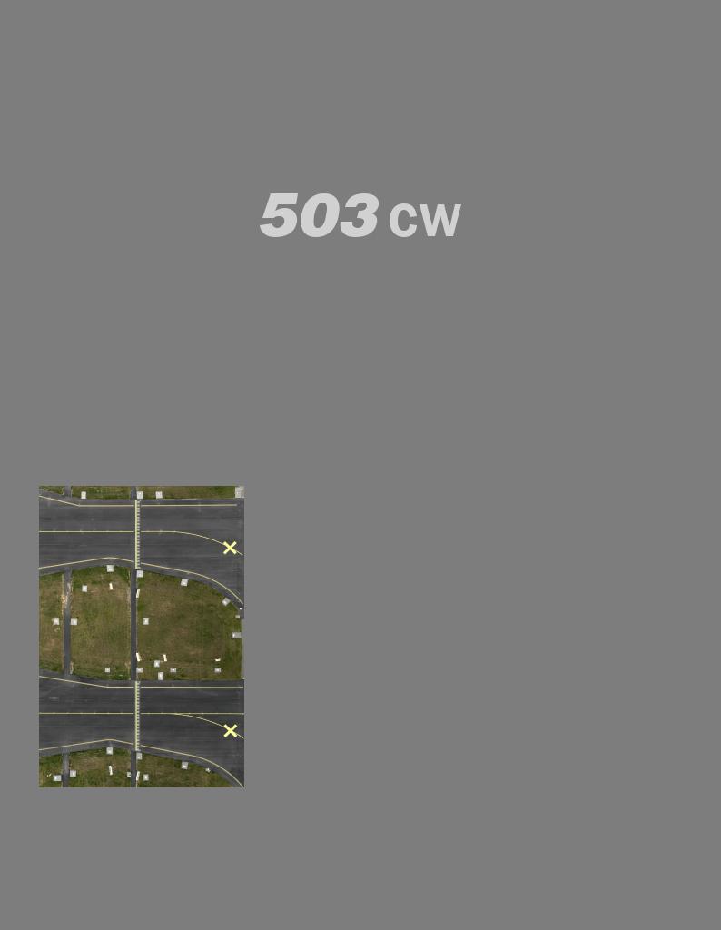
In the diagrams, all exit pupils are viewed from the image corners.
Diagram A
Exit pupil for a wideopen lens
A
Diagram B
Exit pupil for a vignette-free stopped down lens
B
Diagram C
Exit pupil for a slightly vignetted lens (no visible effect on the image) C
Diagram D
Exit pupil for a vignetted lens (clearly visible effect on the image)
D
Rear cover MultiControl (supplied)
The Rear Cover MultiControl (3051070) not only provides protection for the camera body when a CFV or film magazine is not attached but also provides flash check facility for cameras featuring TTL/OTF (described separately) as well as a vignetting check facility.
Checking for possible vignetting is useful when filter combinations, attachments or lens shades are used, to ensure the optimum from the accessories without the risk of inadvertant vignetting.
With the cover in position you can see the so-called ‘exit pupil’ of the lens through the small holes in the cover. A vignetting free lens has an exit pupil the exact shape of the lens aperture. At maximum aperture there is slight vignetting with all lenses but at f/11 to f/16 the majority of lenses are free of vignetting.
Corner illumination is dependent on the size of the exit pupil. If the filter or lens shade extends too far, the area of the exit pupil diminishes. The shading effect of a professional lens shade, for example, is optimal when it has been extended as far as possible without causing any visible corner vignetting. The amount of this extension is dependent on both the working aperture and the focusing distance for the lens used.
Use the following method when any kind of lens accessory is in place and you want to ensure a result free from vignetting:
1.Fit the accessory. Remove the film magazine but do not attach a Rear Cover MultiControl just yet.
2.Set the shutter on a CF/CFi/CFE lens at the ‘F’ position and pre-release the camera to open both the lens shutter and the auxiliary shutter. C/CB lens shutters should be set at ‘B’ and a B exposure made. Use a cable release to lock the released position.
3.Look at the lens exit pupil. Use the stop-down button and change the aperture noticing as you do so the changes in the size of the exit pupil.
4.Look now at an angle roughly in a line from the exit pupil to one corner of the camera back opening. This helps in finding the exit pupil again when the RCMC is attached, which can be troublesome with wide-angle lenses in particular.
5.Attach the RCMC and observe the exit pupil again.
6.Select the working aperture and stop down manually.
7.Set the approximate focusing distance.
8.See the diagrams for a fuller explanation of what you can now see through one of the holes, and act accordingly.
Optional accessories
As the 503CW / 503CWD models are further developments of previous models, they feature improvements and some differences in design. This means that certain older and now discontinued accessories cannot be used and any forced attempt at mounting them may damage your equipment, so please check carefully before trying. For example, the PM/PME 90 viewfinders and the ArcBody are not compatible with the CFV-39 or CFV-50 for different reasons but are both compatible with film magazine use. For complete and up to date information please visit our website - www.hasselblad. com. The following list is just a selection (some are discontinued but may still be available).
Viewfinders
A prism viewfinder with a 45° viewing angle that provides an un-reversed 2.5X magnified focusing screen image. The large eyepiece, especially suitable for users with eyeglasses, has a diopter adjustment range of - 2 to + 1 diopters.
25

Winder CW
The Winder CW is a compact, economically designed unit providing not only a motor drive facility but also a comfortable and robust grip.
It features single exposure, continuous exposure as well as multi-exposure modes. Remote control is achieved by a simple release cord or by the unique infrared transmitter − the Hasselblad IR Remote control. Both provide considerable freedom, with the IR Remote control offering an extra remote mode choice facility. Each winder is governed by a unique code from the IR Remote control so there is no risk of controlling other cameras unintentionally. However, one IR Remote control can control several cameras at the same time if desired. As the winder is set close to the camera body, it produces stability and balance for optimum hand held efficiency.
Requires an ‘Exposure Cable 503’ when used with a CFV. See MENU > SETTINGS > Camera for use.
Tripod quick-coupling
The coupling plate on the bottom of the camera body has both a 1/4 in. and a 3/8 in. tripod thread. It also fits the useful and reliable Hasselblad Tripod Quick-Coupling (3043326). This facilitates rapid and repeatedly accurate attachment and removal of the camera from a tripod or support.
Professional lens shade
The Proshade 6093T (3040739) provides the ultimate in flare and stray light reduction. It is particularly useful if you have a number of lenses as it fits virtually all lenses in the range. It is supplied with a Proshade mask 6093/250 (3040312) which provides further control for longer lenses when the Proshade is fully extended. The Proshade also functions as a gelatine filter holder.
Close-up accessories
Four fully automatic extension tubes are available for close-up work. With the exception of Extension tube 8, which cannot be connected directly to the 200-series cameras, they also feature a data bus coupling to transfer data from the lens to the exposure metering system of the camera.
Film magazine
The Magazine A12 produces 12 frames with 120 film (6x6 cm) and is available in chrome.
Please visit the Hasselblad website − www.hasselblad.com − for details of the complete range of accessories and lenses.
There are a number of discontinued accessories for the V-system on the used market but please check for compatibility.
26

Technical specifications — 503CW camera body
Camera type:
Design:
Viewfinder:
Film advance:
Flash control:
Tripod coupling: External dimensions: Weight:
Focusing screen
Single lens reflex camera with 6 x 6 cm (2 1/4 x 2 1/4 in) max. film size. Interchangeable lenses, film magazines, viewfinders, and focusing screens.
Mechanical, with an aluminum alloy camera body shell cast in one piece.
Folding focusing hood interchangeable with reflex viewfinder, prism viewfinders with or without builtin light meter, or magnifying hood.
Manual advance or motor driven with Winder CW. Simultaneous shutter winding. Winder CW winding time: 1.05 s, approx. 0.8 frames/sec in continuous mode.
TTL/OTF-metering. ISO 64−4000 with flash/strobe adaptors SCA390 for connection with flash/strobe units from the SCA 300 systems. Metering area within 40 mm diameter in the centre of the image area.
1/4 in. and 3/8 in. socket threads and base plate for quick coupling attachment.
Complete camera with Planar CFE 2.8/80 mm lens: 193mm L x113mm W x110mm H
1620 g (Excluding battery and CF card).
Hasselblad Acute-Matte D focusing screen with sensor format markings.
Troubleshooting — 503CW
Hasselblad equipment is built to give long and trouble-free service, especially when you follow the maintenance and care advice at the end of this manual. If however you encounter any operating difficulties because you are not familiar with the camera system, the following table may help to resolve them. If the problem persists and the camera is still under guarantee, you should contact your Hasselblad dealer. If the guarantee has expired, you should contact a Hasselblad Authorised Service Center for advice.
Problem |
Possible cause |
Remedy |
There is no image on the focusing |
• Thecameraisinthepre-releasedor |
• Completethecamerareleaseandrewind |
screen |
released position |
the camera |
|
• Thelenscapisstillinplace |
• Removethelenscap |
You cannot remove the front |
• Thecameraisinthepre-releasedor |
• Completethecamerareleaseandrewind |
protective cover |
released position |
the camera |
You cannot attach the lens |
• Thelensisinthereleasedposition |
• Windthelens |
|
• Thecamerabodyisinthepre-released |
• Completethecamerareleaseandrewind |
|
or released position |
the camera |
You cannot remove the lens |
• Thecamerabodyisinthepre-released |
• Completethecamerareleaseandrewind |
|
or released position |
the camera |
|
|
|
27

1
Overview
Photo: Claudio Napolitan / Hasselblad Masters
28
 Loading...