


Installation & Operating Manual
The Harman SF1500A, SF2500A, SF2600A, SF 3500A
R4
SAFETY NOTICE
Please read this entire manual before you install and use your heating appliance. Failure to follow instructions may result in property damage, bodily injury, or even death.
FOR USE IN THE U.S. AND CANADA. Not SUITABLE FOR INSTALLATION IN MOBILE HOMES
IF THIS HARMAN STOVE IS NOT PROPERLY INSTALLED, A HOUSE FIRE MAY RESULT. FOR YOUR SAFETY, FOLLOW INSTALLATION DIRECTIONS.
CONTACT LOCAL BUILDING OR FIRE OFFICIALS ABOUT RESTRICTIONS AND INSTALLATION INSPECTION REQUIREMENTS IN YOUR AREA.
Contact your local authority (such as municipal building department, fire department, fire prevention bureau, etc.) to determine the need for a permit.
Cette guide d’utilisation est disponible en francais. Chez votre concessionnaire de Harman
Stove Company.
R1
save these instructions.
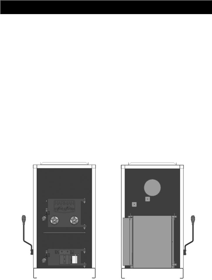
Table of Contents
Packing List |
3 |
Installation |
5 |
Mounting Blower & Filter Box |
7 |
Wiring |
8 |
Duct Work |
11 |
Operation |
11 |
Safety Tips |
13 |
Chimney Troubleshooting |
13 |
Maintenance |
14 |
Specifications |
15 |
Coil Installation |
16 |
Oil Burner Setup |
18 |
Warranty |
19 |
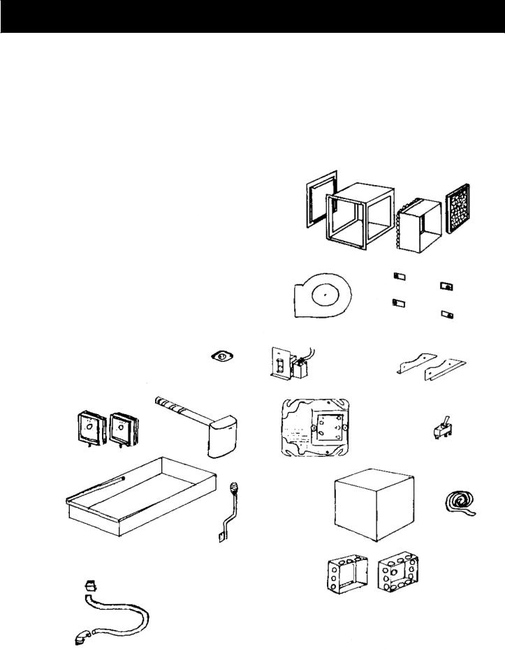
Packing List - SF2600
Blue Angel Oil Burner Burner Gasket Automatic Draft Control Blower
(2) Blower Brackets
Filter Box Kit (3 pieces) + Filter Fan Control / High Limit
3-Speed Fan Switch (not on SF3500)
(2) Thermostats
(2) Junction Boxes Relay
High Limit Snap Disc
(4) 1/4 X 3/4 bolts & (4) Filter Box Mounting Clips 36” Flex Conduit
(1) Straight Conduit Fitting
(1) Elbow Conduit Fitting Ash Pan
Shaker Handle
Owner’s Manual Warranty Registration
Snap Disc
Filter
Filter Box Kit
Filter Box
Mounting Clips
Blower
Automatic Draft Control |
Blower Brackets |
Fan Control /
High Limit
3- Speed Fan Switch
Thermostats
Relay
Oil Burner Gasket
Oil Burner
Ash Pan |
Shaker Handle |
|
Junction Boxes
FlexConduit and Fittings
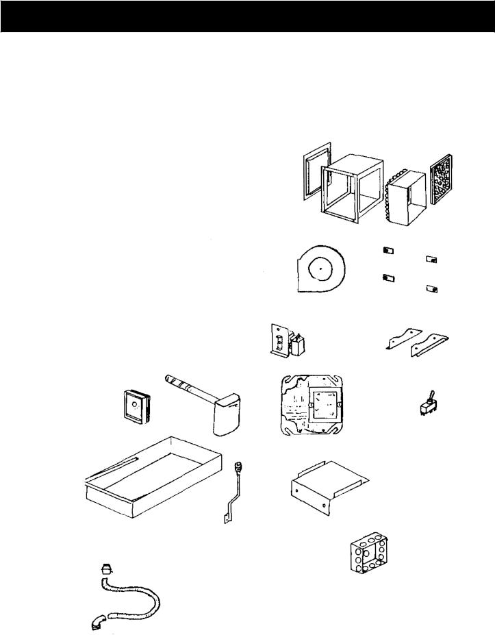
Packing List for SF1500, SF2500 & SF3500
Blower Mounting Plate w/ 2= 5/16X3/4 bolts ( SF3500 Only) Automatic Draft Control
Blower
(2) Blower Brackets
Filter Box Kit (3 pieces) + Filter Fan Control / High Limit
3-Speed Fan Switch (not on SF3500) Thermostat
Junction Box Relay
(4) 1/4 X 3/4 bolts & (4) Filter Box Mounting Clips 36” Flex Conduit
(1) Straight Conduit Fitting
(1) Elbow Conduit Fitting Ash Pan
Shaker Handle
Owner’s Manual Warranty Registration
Blower
Automatic Draft Control
Fan Control /
High Limit
Thermostat
Relay
Ash Pan
Shaker Handle
Flex Conduit & Fittings
Filter
Filter Box Kit
Filter Box
Mounting Clips
Blower Brackets
3-Speed Fan Switch
Blower Mount-
SF3500 only
Junction Box
Furnace Installation
To ensure a safe installation, it is recommended that this furnace be installed by a qualified installer.
The sheet metal top and sides can be easily removed to reduce the chance of dents or scratches on the painted surfaces.
To remove the sheet metal, first lift off the top section. Now, the sides can be removed by lifting up and out away from the furnace.
To lighten the SF2600, the oil burner heat exchanger should be removed. Do so by first removing the sheet metal as described above. Remove the front sheet metal by first removing the burner collar. Now remove the the two long bolts on each side of the heat exchanger.(Figure B) The entire unit can now be lifted off and moved separately.
Caution: This furnace must not be installed closer than 24 inches at the sides and 30 inches from the rear to
combustible materials. The unit may Figure A
only be installed on a non-combustible floor surface such as concrete floor or concrete pad on dirt floor. The hot air plenum must be a minimum of 2 inches from the ceiling or other combustibles above the plenum.
Locate the furnace as close to the chimney as possible while still maintaining the above clearances. No more than 8 feet of stovepipe should be used, including two or less 90° elbows. All horizontal runs of pipe should have a minimum 1/4 in. rise per foot. All stove pipe must be 24 gauge or thicker.
When re-installing the heat exchanger, inspect the gasket around the furnace opening, and replace if necessary. (Figure A) Place the heat exchanger in position and secure with the long bolts and nuts. Be sure the gasket is compressed evenly.
Re-install the sheet metal by sliding the groove on the bottom of each side panel over the steel lip on the furnace. The top sheet metal piece holds the sides in place. The SF2600 front cover gets installed by angling the bottom edge over the lip on the top of the firebox. The side edges must slide into the grooves on each side and pushed in flush with the sides and top. This front piece is held in place by the black ring which gets tightened around the burner pipe. Do not over tighten as this will push the sheet metal in too far.
Inspect Gasket prior to reinstalling heat exchanger.
 (4) 12in. bolts, two on each side, attach the heat exchanger to the furnace.
Figure B
Furnace Installation
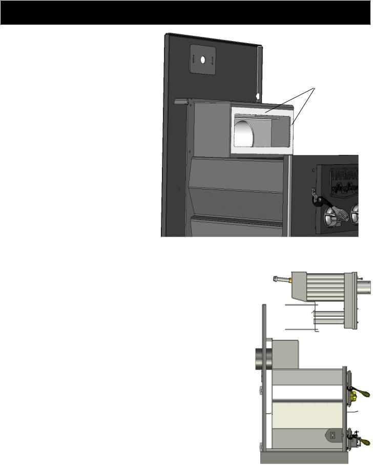
Installing Wood/Coal High Limit Switch-
SF2600 only.
First, install the sheet metal sides as described in the previous section. Install the snap disc switch into the hole on the right side sheet metal. Then mount the open backed junction box around the snap switch. Proceed with wiring as shown on page 10. Also refer to Figure D. in this section.
Mounting The Oil Burner- SF2600 only. Remove oil burner unit from it’s box. Loosen
the four bolts in the pipe on the front of the furnace. Insert the nose of the oil gun into the pipe. Before sliding the oil burner all the way in, apply the gasket around the nose of the oil gun by wrapping it around the nose. Next, slide the oil burner into the pipe and secure it by tightening the four bolts around the collar. Be sure to tighten the bolts evenly to locate the oil burner in the center of the pipe. The final set-up of the oil burner should be done by an experienced oil burner technician with the proper equipment. Refer to the SF2600 wiring diagram on page 10 and the oil burner manual for proper burner set-up. There is also a section at the end of this manual with specific oil burner instructions.
Venting Guidelines.
Your Harman hot-air furnace must be vented to it’s own separate flue-lined “Class A” chimney, not less than 8” X 8” in size. The chimney must be capable of providing a draft reading of at least .06” water column on a draft meter, in order to function properly. The Chimney must be a minimum of 16
ft. high, and must be two feet higher than anything within 10 ft. The chimney must also be at least 3 ft. higher than the point at which it exits or passes by the roof. A barometric damper must be installed in the flue to eliminate excessive draft. Any horizontal sections of connector pipe must have at least 1/4 in. per foot rise. Limit the number of elbows to two or less. All joints in the connector pipe must be secured with sheet metal screws.
Assembly.
Bolt the shaker handle to the block on the lower left side of the furnace, using the bolts and lock-washers provided.
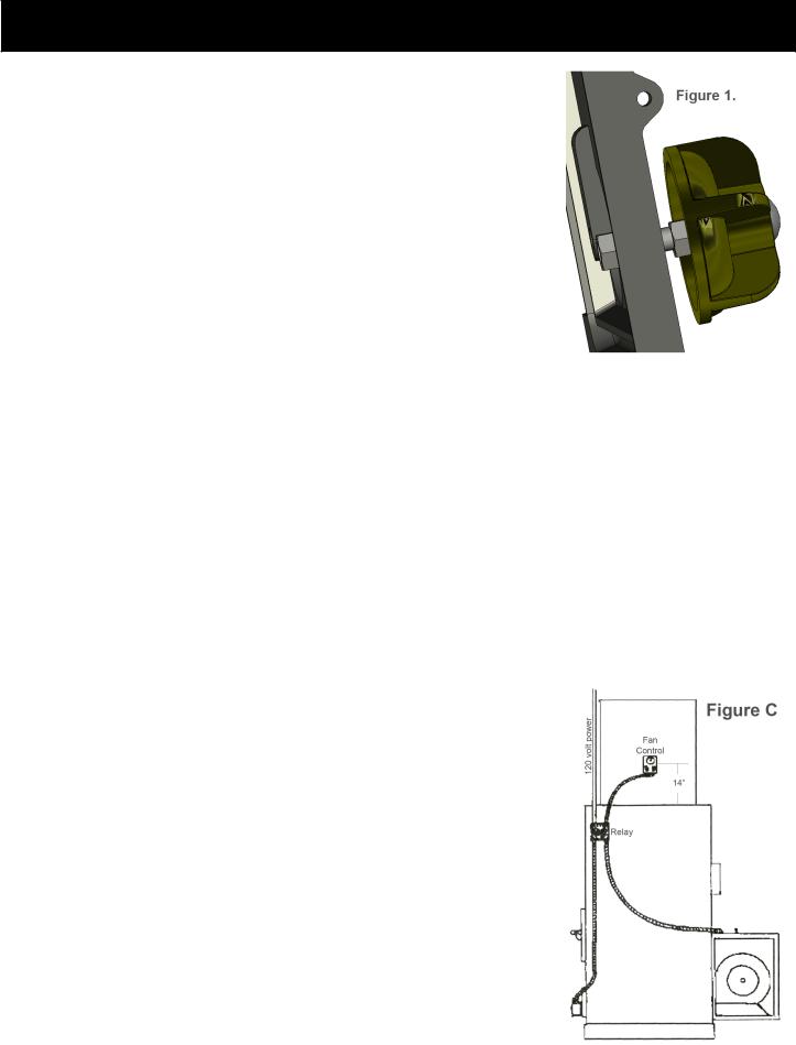
Bolt the two manual draft controls to the front load door. Proper installation allows the draft controls to open approximately 1/2” from the door surface. See Figure 1.
Bolt the automatic draft control to the bottom door. Be sure to hold the unit straight while tightening. After the automatic draft control
is mounted, the two wires must be strung through the flexible conduit and two fittings supplied. The knockout plug of the junction box must be removed to install the conduit fitting.
Check the door of the
automatic draft control to assure proper operation. Warning: Keep pieces of wood or coal out of the draft door opening mechanism, as this could cause the door to stick.
NOTE: Oil the hinge at the begining of the heating season with a light oil.
The junction box is best mounted on the side of the furnace about 1 in. back and 8 in. from the top of the sheet metal side. (fig. C or D) If this location is inconvenient, anywhere on the right side will work.
SF1500, SF2500, SF3500.
This figure represents the models; SF1500,
SF2500, and SF3500. It’s intention is to represent the approximate location of the various controls. This drawing may also be used as a recommendation for routing of the
wiring and approximate dimension of control spacing.
Please note that this drawing is for reference only. Each specific installation will vary.
 Loading...