


Installation & Operating Manual
P61A-2 Pellet Stove Owners Manual
Safety Testing by
ASTM E1509
Mobile Home Approved
ìCe manuel est disponible en FranÁais sur demandeî |
R5 |
SAFETY NOTICE
PLEASE READ THIS ENTIRE MANUAL BEFORE YOU INSTALLAND USE YOUR NEW ROOM HEATER. FAILURE TO FOLLOW INSTRUCTIONS MAY RESULT IN PROPERTY DAMAGE, BODILY INJURY, OR EVEN DEATH.
FOR USE IN THE U.S. AND CANADA. SUITABLE FOR INSTALLATION IN MOBILE HOMES
IF THIS HARMAN STOVE IS NOT PROPERLY INSTALLED, A HOUSEFIRE MAY RESULT. FOR YOUR SAFETY, FOLLOW INSTALLATION DIRECTIONS.
CONTACT LOCAL BUILDING OR FIRE OFFICIALS ABOUT RESTRICTIONSAND INSTALLATION INSPECTION REQUIREMENTS IN YOUR AREA.
CONTACT YOUR LOCAL AUTHORITY (SUCH AS MUNICIPAL BUILDING DEPARTMENT, FIRE DEPARTMENT, FIRE PREVENTION BUREAU, ETC.) TO DETERMINE THE NEED FOR A PERMIT.
CETTE GUIDE D'UTILISATION EST DISPONIBLE EN FRANCAIS. CHEZ VOTRE CONCESSIONNAIRE DE HARMAN
STOVE COMPANY. |
R1 |
|
SAVETHESEINSTRUCTIONS.

Fig. 1
2 P61A Pellet Stove

Table of Contents
|
Testing Lable |
2 |
|
|
Assembly & Installation |
4 |
|
|
Installation |
5 |
|
|
Venting |
6 |
|
|
Automatic Operation |
12 |
|
|
ESP Control |
16 |
|
|
Maintenance |
17 |
|
|
Trouble Shooting |
22 |
|
|
Feeder Parts |
23 |
|
|
Specifications |
23 |
|
|
Options |
24 |
|
|
Wiring Diagram |
26 |
|
|
Parts List |
27 |
|
|
Warranty |
28 |
|
|
|
|
|
|
|
|
|
Please read this entire manual before you install and use your new room heater. Failure to follow instructions may result in
property damage, bodily injury, or even death.
SUITABLE FOR MOBILE HOME INSTALLATIONS.
Harman Stove Company
352 Mountain House Road
Halifax, PA 17032
P61A Pellet Stove 3
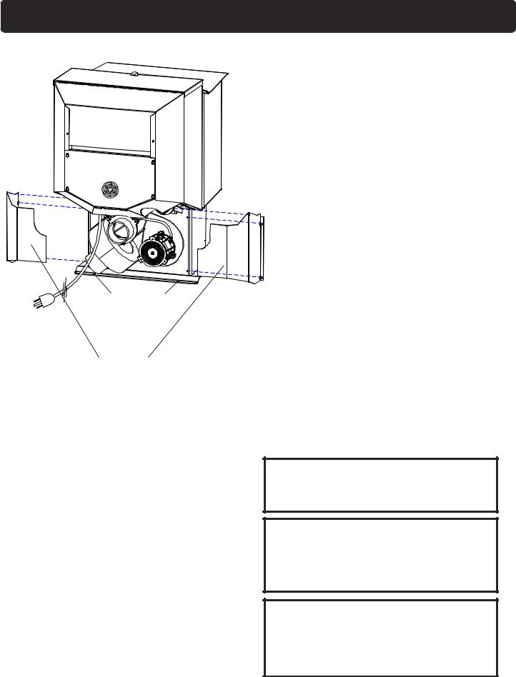
Assembly and Installation
Shipping Bolts Note: These same holes are used for mobile home installation
Rear Cover
Panels
Fig. 2
Unpacking
The P61 is bolted to the skid to prevent movement duringshipping.
To free the stove from the skid you must remove the hold-down bolts in the rear of the pedestal base.
Removing or Installing rear cover panels
To remove the rear cover panels, loosen the screws slightly and slide the covers outward as shown in the illustration. To reinstall, simply slide back into place and retighten the screws.
Firebrick
Install the firebrick vertically on the angle above the burnpot.
Flame Guide
Install the cast iron flame guide on top of the burnpot and make sure it is fully seated against the augeropening.Thebottomoftheflameguideismarked
38+.
DO NOT INSTALLA FLUE DAMPER IN THE EXHAUST VENTING SYSTEM OF THIS UNIT.
DO NOT CONNECT THIS UNIT TO A CHIMNEY FLUE SERVINGANOTHER APPLIANCE.
INSTALLVENTAT CLEARANCES SPECIFIED BYTHE MANUFACTURER
Mobile home installation should be done in accordance with the Manufactured Home and Safety Standard (HUD), CFR 3280, Part 24.
4 P61A Pellet Stove
WARNING
DO NOT INSTALL IN SLEEPING ROOM
CAUTION
THE STRUCTURAL INTEGRITY OF THE MOBILE HOME FLOOR, WALL, AND CEILING/ROOF MUST BE MAINTAINED.
CAUTION
KEEPCOMBUSTIBLE MATERIALS (SUCHAS GRASS, LEAVES, ETC.)AT LEAST 3
FEETAWAYFROMTHE FLUE OUTLETON THE OUTSIDE OF THE BUILDING.
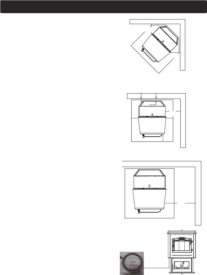
Installation
Installing
Place the stove on a noncombustible floor protector that extends 6 inches to the front, 6 inches to the sides and 1 inch to the rear of the stove. The minimum floor protector material is 24 gauge sheet metal.
Place the stove away from combustible walls at least as far as shown in figures 3,4 and 5. Please note the difference in side wall clearance with and without side shields.
Note that the clearances shown are minimum for safety but do not leave much room for access when cleaning or servicing. Please take this into account when placing the stove.
Connect the power cord to a 120 V.A.C. 60Hz grounded receptacle. (A surge protector is recommened to protect the circuit board).
Prior to installing the flue pipe, connect a draft meter to the stove as shown in fig. 6. (The draft meter must have a minimum range of 0-.5). However, prior to taking the draft reading be sure all doors and windows in the home are closed. Record the draft reading_______. If this reading is more than .05" lower than the unconnected reading, check for possible restrictions or the need for outside air (see page 7).
Mobile Home Installation
When installing this unit in a mobile home several requirements must be followed:
1.The unit must be bolted to the floor. This can be done with 1/4" lag screws through the 2 holes in the base plate.
2.The unit must also be connected for the outside air. See page 8.
3.Floor protection and clearances must be followed as shown.
4.Unit must be grounded to the metal frame of the mobile home.
CAUTION: This appliance must be vented to the outside.
Due to high temperatures, the stove should be placed out of traffic and away from furniture and draperies.
Children and adults should be alerted to the hazards of high surface temperatures and should stay away to avoid burn to skin and/or clothing.
Young children should be carefully supervised when they are in the same room as the stove.
Clothing and other flammable materials should not be placed on or near this unit.
Installation and repair of this Harman Stove should be done by a qualified service person. The appliance should be inspected before use and at least annually by a qualified service person. More frequent cleaning will be required. It is imperative that control compartments, burners, and circulating air passageways of the stove be kept clean.
9"-13"
FLOOR |
|
PROTECTOR |
9"-13" |
|
9" With Side Shields
13" Without Side Shields
Fig. 3
1" |
2" |
|
|
|
|
12" |
Shields |
6" |
|
6" |
|
FLOOR PROTECTOR |
6" |
With Side |
|
|
|
||
|
Fig. 4 |
|
|
18"
FLOOR PROTECTOR
Fig. 5
Without Side Shields
Fig. 6 |
P61A Pellet Stove 5 |

Venting
Requirements for Terminating the Venting
WARNING: Venting terminals must not be recessed into a wall or siding.
NOTE: Only PL vent pipe wall pass-throughs and fire stops should be used when venting through combustible materials.
NOTE: Always take into consideration the effect the prevailing wind direction or other wind currents will cause with flyash and /or smoke when placing the termination.
In addition, the following must be observed:
A.The clearance above grade must be a minimum of 18".1
B.The clearance to a window or door that may be opened must be a minimum of 48" to the side, 48" below the window/door, and 12" above the window/door.1
( with outside air installed, 18î )
C.A 12" clearance to a permanently closed window is recommended to prevent condensation on the window.
D.The vertical clearance to a ventilated soffit located above the terminal within a horizontal distance of 2 feet (60 cm) from the center-line of the terminal must be a minimum of 18".
E.The clearance to an unventilated soffit must be a minimum of 12".
F.The clearance to an outside corner is 11" from center of pipe.
G.The clearance to an inside corner is 12".
H.A vent must not be installed within 3 feet (90 cm) above a gas meter/regulator assembly when measured from the horizontal center-line of the regulator.1
I.The clearance to service regulator vent outlet must be a minimum of 6 feet.1
J.The clearance to a non-mechanical air supply inlet to the building or the combustion air inlet to any other appliance must be a minimum of 48î.1
K.The clearance to a mechanical air supply inlet must be a minimum of 10 feet.1
(with outside air installed, 6 feet )
L.The clearance above a paved sidewalk or a paved driveway located on public property must be a minimum of 7 feet.1,2
M. The clearance under a veranda, porch, deck or balcony must be a minimum of 12 inches.1,3
NOTE: The clearance to vegetation and other exterior combustibles such as mulch is 36î as measured from the center of the outlet or cap. This 36î
radius continues to grade or a minimum of 7 feet below the outlet.
1Certain Canadian and or Local codes or regulations may require different clearances.
2A vent shall not terminate directly above a sidewalk or paved driveway which is located between two single †family dwellings and serves both dwellings.
3Only permitted if veranda, porch, deck, or balcony is fully open on a minimum of 2 sides beneath the floor.
NOTE: Where passage through a wall, or partition of combustible construction is desired, the installation shall conform to CAN/CSA-B365. (if in Canada)
Inside Corner
Detail
Fixed |
|
|
Closed |
Openable |
Fixed |
Openable |
|
Closed |
|
|
|
|
V |
= Vent terminal |
A = Air supply inlet |
= Area where terminal is not permitted |
6 |
P61A |
Pellet Stove |
|
|
|
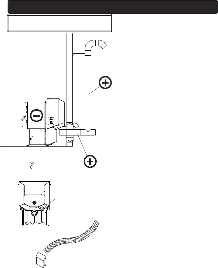
Venting
IMPORTANT NOTICE
Pellet Vent Pipe or PL Vent Pipe Must be used.
Fig. 7
+ = Positive static pressure = Negative static pressure
Outside air flex pipe goes here
Flex pipe part# 2-00-08543
Inlet Cover part# 1-10-08543
Venting
A combustion blower is used to extract the combustion gases from the firebox. This causes a negative pressure in the firebox and a positive pressure in the venting system as shown in fig. 7. The longer the vent pipe and more elbows used in the system, the greater the flow resistance. Because of these facts we recommend using as few elbows as possible and 15 feet or less of vent pipe. The maximum horizontal run should not exceed 48". If more than 15 feet of pipe is needed, the diameter should be increased from 3" to 4" because a larger pipe causes less flow resistance. Be sure to use approved pellet vent pipe wall and ceiling pass through fittings to go through combustible walls and ceilings. Be sure to use a starting collar to attach the venting systen to the stove. The starting collar must be sealed to the stove with high temp silicone caulking.
Vent Pipe
Pellet venting pipe ( also known as PL vent ) is constructed of two layers with air space between the layers. This air space acts as an insulator and reduces the outside surface temperature to allow a clearance to combustibles of only 3 inches. The sections of pipe lock together to form an air tight seal in most cases; however, in some cases a perfect seal is not achieved. For this reason and the fact that the P61 operates with a positive vent pressure we specify that the joints also be sealed
with clear silicone.
Outside Air
Outside air is optional except in mobile homes and where building codes require. The benefit of outside air is mainly noticed in small very tight houses.
To install outside air use 2 3/8" I.D. flex pipe part number 2-00-08543. There is a break-away hole on the rear panel which must be removed before connecting the flex pipe. The pipe should be run outside and terminate to the side or below the vent pipe outlet so the flueoutletismorethan12"fromtheinletcover.Themaximum length run of this pipe is 15 feet. If a longer run is needed the size must be increased to 3". Inlet cover part number 1-10-08542 should be used to keep birds, rodents etc. out of the pipe.
HRV.
When installing in a house with a Heat Reclaiming Ventilation System (HRV) be sure the system is balanced and is not creating a negative pressure in the house.
P61A Pellet Stove 7
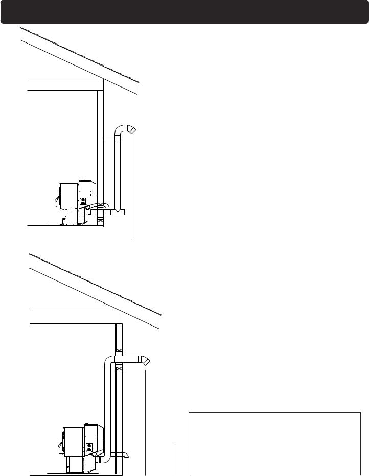
Venting
#1 Preferred method
This method provides excellent venting for normal operation and allows the stove to be installed closest to the wall.Two inches from the wall is safe; however, four inches allows better access to remove the rear panel. The vertical portion of the vent should be three to five feet high. This vertical section will provide natural draft in the event of a power failure.
|
|
|
|
|
3 ft. |
|
|
|
|
|
|
|
|
|
|
|
|
|
|
|
|
|
|
|
|
|
|
|
|
|
|
|
|
|
|
|
Fig. 8 |
|
|||
|
|
|
|
|
to combustibles |
|
3 ft.
to combustibles
Fig. 9
8 P61A Pellet Stove
#2 Preferred method
This method also provides excellent venting for normal operation but requires the stove to be installed farther from the wall. The vertical portion of the vent should be three to five feet high and at least three inches from a combustible wall. This vertical section will provide natural draft in the event of a power failure.
If the stove is installed below grade be sure the vent termination should be at least 1 foot above grade.
CAUTION
Keep combustible materials (such as grass, leaves, etc.) at least 3 feet away from the flue outlet on the outside
of the building.
Venting
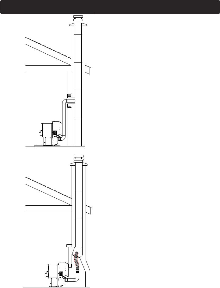
#4 Installing into an existing chimney ( US only )
This method provides excellent venting for normal operation. This method also provides natural draft in the event of a power failure. If the chimney condition is questionable you may want to install a liner as in method #7.
Fig. 10
#5 Installing into an existing fireplace chimney ( US only )
This method provides excellent venting for normal operation. This method also provides natural draft in the event of a power failure.
The damper area must be sealed with a steel plate or fiberglass. A cap should be installed on the chimney to keep out rain. If the chimney condition is questionable you may want to install a liner all the way to the top as in method #6.
Fig. 11 |
P61A Pellet Stove 9 |
|
 Loading...