


Installation & Operating Manual
The Harman PP38+ Pellet Stove
“Ce manuelest disponibleenFrançaissurdemande”
SAFETY NOTICE
Tested byIntertek Testing Service Tested to: UL 1482,ASTM E1509-95, Oregon 814-23-900 THRU814-23-909,
ULC-S627-M90, WH-PN 025
R8
PLEASE READ THIS ENTIRE MANUALBEFORE YOU INSTALL AND USE YOUR NEW ROOM HEATER. FAILURE TO FOLLOW INSTRUCTIONS MAY RESULT IN PROPERTYDAMAGE, BODILY INJURY, OR EVEN DEATH.
FOR USE IN THE U.S. AND CANADA. SUITABLE FOR INSTALLATION IN MOBILE HOMES
IF THIS HARMAN PELLET STOVE IS NOT PROPERLY INSTALLED,AHOUSEFIREMAYRESULT. FORYOUR SAFETY, FOLLOW INSTALLATION DIRECTIONS.
CONTACT LOCAL BUILDING OR FIRE OFFICIALSABOUT RESTRICTIONSAND INSTALLATION INSPECTION REQUIREMENTS IN YOUR AREA.
CONTACT YOUR LOCAL AUTHORITY (SUCH AS MUNICIPAL BUILDING DEPARTMENT, FIRE DEPARTMENT, FIRE PREVENTION BUREAU, ETC.) TO DETERMINE THE NEED FORA PERMIT.
CETTEGUIDE D'UTILISATIONEST DISPONIBLE EN FRANCAIS. CHEZ VOTRE CONCESSIONNAIRE DEHARMANSTOVE COMPANY.
SAVE THESE INSTRUCTIONS.

Contents
P38+ Pellet Stove
Assembly & Installation |
4 |
Venting |
8 |
Turbo Control |
12 |
Operation |
13 |
Maintenance |
14 |
Trouble Shooting |
16 |
Feeder Parts |
17 |
Specifications |
17 |
Wiring Diagram |
18 |
Options |
19 |
Warranty |
22 |
Please read this entire manual before you install and use your new room heater. Failure to follow instructions may result in
property damage, bodily injury, or even death.
SUITABLE FOR MOBILE HOME INSTALLATIONS.
SAVE THESE INSTRUCTIONS
Harman Stove Company
352 Mountain House Road
Halifax, PA 17032
3
Assembly and Installation
P38+ Pellet Stove
Unpacking
Cut straps holding box together and remove box from
skid.
The 38+ is bolted to the skid to prevent movement during shipping.
To free the stove from the skid you must remove the hold-down bolts in the rear of the pedestal base.
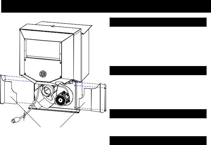
Installing Rear Cover Panels
The rear cover panels are removed from the stove to make it easier to get at the hold-down bolts.
The rear cover panels are packed inside the hopper and should be installed on the stove as shown. This should be done after the stove is in place and flue is connected.
Firebrick
Install the firebrick horizontally on the angle above the
burnpot.
Rear Cover Panels
Flame Guide
Install the cast iron flame guide on top of the burnpot and make sure it is fully seated against the auger opening. The bottom of the flame guide is marked 38+.
4
Door Assembly/Installation Tips
P38+ Pellet Stove
Assembling the door |
|
Door Glass |
|
|
|
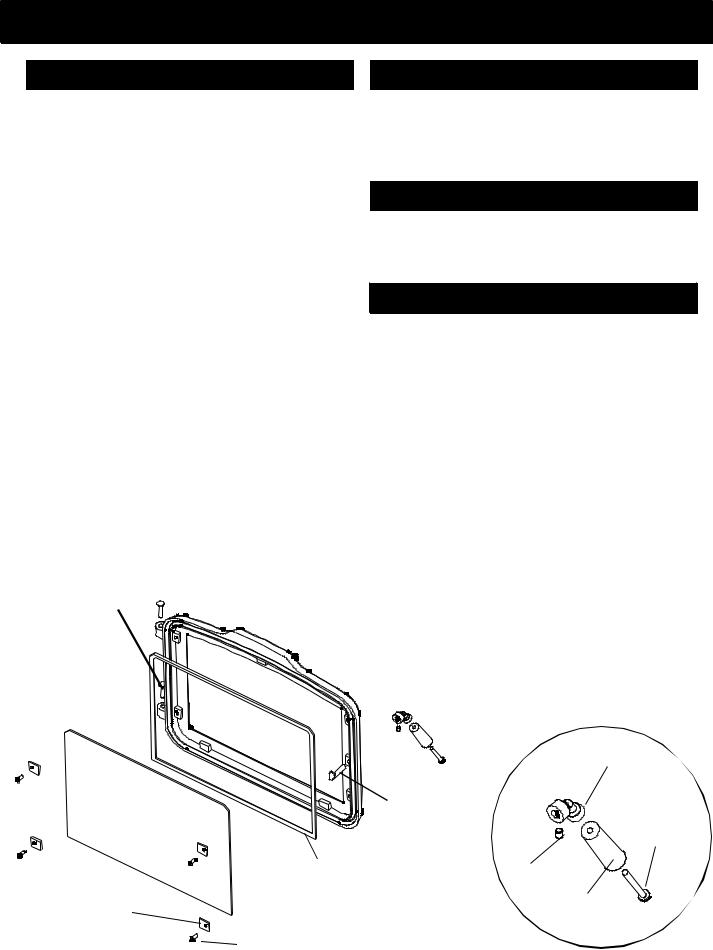
Referring to the diagram, note how the various components of the door system fit together. Lay the load door face down on a soft surface.
Clean the glass and gold door using a nonabrasive cleaner. Install the glass gasket around the outer edge of the front face of the door glass carefully to insure proper sealing. Set the glass pane gently onto the door. Install the hold-down clips and tighten with bolts as shown.
Install door on stove with hinge pins.
Install door handle as shown on the diagram. NOTE: With the flat surface of the paw bolt to the inside of the door.
Turn the paw bolt "in" for approx. (17) turns.
Turn the brass elbow onto the paw bolt approx. (5) turns. Align the set screw with the flat spot on the paw and
tighten.
After attaching the door handle, close and latch the door by turning the handle to the six o'clock position. Does the door rope compress? If not, loosen the set screw, turn the paw bolt one more turn into the door. Repeat as required to achieve a tight door fit.
NOTE: Remember to thoroughly clean the glass and the gold door frame before lighting the stove for the first time.
*Rope the glass carefully to insure proper sealing.
*Apply the rope exactly along the edge of the external face of the glass, not overhanging or pressed too far in from the edge.
* |
Make sharp 90o turns at the corners. |
|
* |
Overlap the ends of the rope at the upper left or right corners. |
|
|
|
|
|
Glass Retainer Clips |
|
|
|
|
*Use the glass retainer clips and screws supplied in the door kit.
*Use a 1/8" Allen wrench to tighten the glass clips to cast door with 10-24 x 3/8" screws supplied.
Paw Bolt
*The paw bolt should be turned into the door from the inside approximately 17 turns.
*With the set screw removed, turn the brass elbow onto the paw bolt approximately 5 turns, or until a 1/16" clearance is achieved between the elbow and the door face (make sure to stop on the flat spot of the paw bolt).
*The set screw on the brass elbow must be aligned to contact the flat spot on the paw bolt, then tighten using a 5/32" Allen wrench.
*After attaching the door handle, close and latch the door by turning the handle to the six o'clock position. During this process observe to see that the door rope is being compressed properly.
*If it does not compress, loosen the set screw and turn the paw bolt one additional turn into the door. Repeat as required to insure a tight seal.
HINGE PINS 

DOOR
BRASS HANDLE
GLASS |
PAW BOLT |
HANDLE
BOLT
|
GLASS GASKET |
SET SCREW |
|
4 GLASS |
|
WOOD HANDLE |
|
RETAINER |
4 GLASS |
||
|
|||
CLIPS |
|
||
RETAINER |
|
||
|
|
||
|
BOLTS |
|
5
Installation
P38+ Pellet Stove
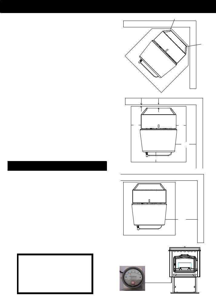
Place the stove on a noncombustible floor protector that extends 6 inches to the front, 6 inches to the sides and 1 inch to the rear of the stove. The minimum floor protector material is 24 gauge sheet metal.
Place the stove away from combustible walls at least as far as shown in figures 3,4 and 5. Please note the difference in side wall clearance with and without side shields.
Note that the clearances shown are minimum for safety but do not leave much room for access when cleaning or servicing. Please take this into account when placing the stove.
Connect the power cord to a 120 V.A.C. 60Hz grounded receptacle. (A surge protector is recommened to protect the circuit board).
Prior to installing flue pipe, connect a draft meter to the stove as shown in fig. 6 . (The draft meter must have a minimum range of 0-.5). Set control board to "1" on the feed rate dial. Record draft reading here _______ (should read at least
.15" cold. Allow combustion blower to operate for approximately 1 minute before recording or adjusting low draft.). See page 19 for low draft adjustment procedures.
After connecting the flue system, follow the above procedure. However, prior to taking the draft reading be sure all doors and windows in the home are closed. Record the draft reading_______. If this reading is more than .05" lower than the unconnected reading, check for possible restrictions or the need for outside air (see page 7).
Mobile Home Installation
When installing this unit in a mobile home several requirements must be followed:
1.The unit must be bolted to the floor. This can be done with 1/4" lag screws through the 2 holes in the base plate.
2.The unit must also be connected for the outside air. See
page 8.
3.Floor protection and clearances must be followed as
shown.
4.Unit must be grounded to the metal frame of the mobile
home.
CAUTION: This appliance must be vented to the outside.
Mobile home installation should be done in accordance with the Manufactured Home and Safety Standard (HUD), CFR 3280, Part 24.
CAUTION
The stove is hot while in operation. Keep children, clothing and furniture away. Contact may cause skin burns.
6
2" |
2" |
FLOOR |
PROTEC |
TOR |
Fig. 3 |
1" |
2" |
|
6" |
6" |
Side Shields |
|
10" |
|
|
6" |
With |
|
|
|
FLOOR PROTECTOR |
|
|
|
Fig. 4 |
|
|
16" |
Side Shields |
|
Without |
|
FLOOR PROTECTOR |
|
|
Fig. 5 |
|
|
Fig. 6

Venting
P38+ Pellet Stove
Requirements for Terminating the Venting
WARNING: Venting terminals must not be recessed into a wall or siding.
NOTE: Only PL vent pipe wall pass-throughs and fire stops should be used when venting through combustible materials.
NOTE: Always take into consideration the effect the prevailing wind direction or other wind currents will cause with flyash and /or smoke when placing the termination.
In addition, the following must be observed:
A.The clearance above grade must be a minimum of 18".1
B.The clearance to a window or door that may be opened must be a minimum of 48" to the side and 48" below the window/door, and 18" above the
window/door.1
(above window/door with outside air installed, 9”)
C.A 12" clearance to a permanently closed window is recommended to prevent condensation on the window.
D.The vertical clearance to a ventilated soffit located above the terminal within a horizontal distance of 2 feet (60 cm) from the center-line of the terminal must be a minimum of 18".
E.The clearance to an unventilated soffit must be a minimum of 12".
F.The clearance to an outside corner is 11" from center of pipe.
G.The clearance to an inside corner is 12".
H.A vent must not be installed within 3 feet (90 cm) above a meter/regulator assembly when measured from the horizontal center-line of the regulator.1
I.The clearance to service regulator vent outlet must be a minimum of 6 feet.1
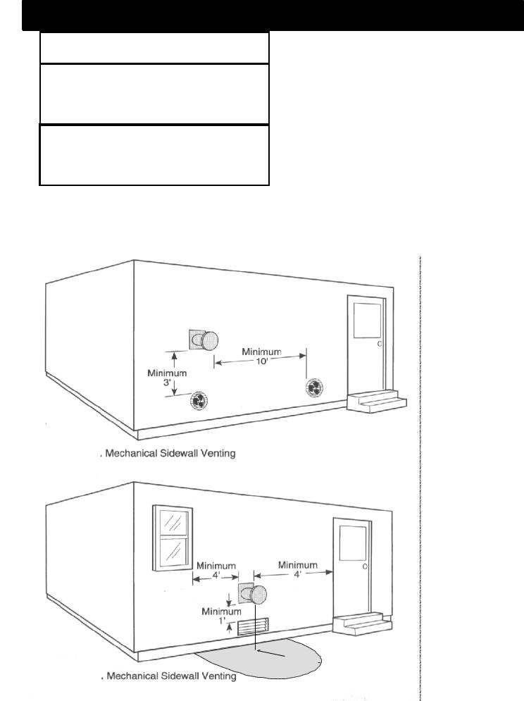
J.The clearance to a non-mechanical air sup-
ply inlet to the building or the combustion air inlet to any other appliance must be a minimum of 48”.1
K.The clearance to a mechanical air supply inlet must be a minimum of 10 feet.1
(with outside air installed, 6 feet )
L.The clearance above a paved sidewalk or a paved driveway located on public property must be a minimum of 7 feet.1,2
M. The clearance under a veranda, porch,deck
or balcony must be a minimum of 12 inches.1,3
NOTE: The clearance to vegetation and other exterior combustibles such as mulch is 36” as measured from the center of the outlet or cap. This 36”
radius continues to grade or a minimum of 7 feet below the outlet.
1Certain Canadian and or Local codes or regulations may require different clearances.
2A vent shall not terminate directly above a sidewalk or paved driveway which is located between two single family dwellings and serves both dwellings.
3Only permitted if veranda, porch, deck, or balcony is fully open on a minimum of 2 sides beneath the floor.
NOTE: Where passage through a wall, or partition of combustible construction is desired, the installation shall conformto CAN/CSA-B365. (if in Canada)
Inside Corner
Detail
Fixed |
|
|
Closed |
Openable |
Fixed |
Openable |
|
Closed |
|
|
V = Vent terminal
A = Air supply inlet |
= Area where terminal is not permitted |
7
Venting
P38+ Pellet Stove
WARNING
DO NOT INSTALL IN SLEEPING ROOM
CAUTION
THE STRUCTURAL INTEGRITY OF THE MOBILE HOME FLOOR, WALL, AND CEILING/ROOF MUST BE MAINTAINED.
WARNING
KEEP COMBUSTIBLE MATERIALS SUCH AS GRASS, LEAVES, ETC. AT LEAST 3 FEET AWAY FROM THE POINT DIRECTLY UNDER THE VENT TERMINATION.
DO NOT INSTALL A FLUE DAMPER IN THE EXHAUST VENTING SYSTEM OF THIS UNIT.
DO NOT CONNECT THIS UNIT TO A CHIMNEY FLUE SERVING ANOTHER APPLIANCE.
INSTALL VENT AT CLEARANCES SPECIFIED BY THE MANUFACTURER.
IMPORTANT NOTICES
•Due to high temperatures, the stove should be placed out of traffic and away from furniture and draperies.
•Children and adults should be alerted to the hazards of high surface temperatures and should stay away to avoid burn to skin and/or clothing.
•Young children should be carefully supervised when
they are in the same room as the stove.
•Clothing and other flammable materials should not be placed on or near this unit.
•Installation and repair of this Harman Stove should be done by a qualified service person. The appliance should be inspected before use and at least annually by a qualified service person. More frequent cleaning will be required. It is imperative that control compartments, burners, and circulating air passageways of the stove be kept clean.
3' 
 Loading...