


Installation & Operating Manual
The Harman Clarity 929 DV
Direct Vent Gas Stove
HA RMAN
“Ce manuelest disponibleenFrançaissurdemande” |
R5 |
SAFETY NOTICE
PLEASE READ THIS ENTIRE MANUALBEFORE YOU INSTALL AND USE YOUR NEW ROOM HEATER. FAILURE TO FOLLOW INSTRUCTIONS MAY RESULT IN PROPERTYDAMAGE, BODILY INJURY, OR EVEN DEATH.
FOR USE IN THE U.S. AND CANADA. SUITABLE FOR INSTALLATION IN MOBILE HOMES
IF THIS HARMAN STOVE IS NOT PROPERLY INSTALLED,AHOUSEFIRE MAYRESULT. FORYOURSAFETY, FOLLOW INSTALLATION DIRECTIONS.
CONTACT LOCAL BUILDING OR FIRE OFFICIALSABOUT RESTRICTIONSAND INSTALLATION INSPECTION REQUIREMENTS IN YOUR AREA.
CONTACT YOUR LOCAL AUTHORITY (SUCH AS MUNICIPAL BUILDING DEPARTMENT, FIRE DEPARTMENT, FIRE PREVENTION BUREAU, ETC.) TO DETERMINE THE NEED FORA PERMIT.
CETTEGUIDE D'UTILISATIONEST DISPONIBLE EN FRANCAIS. CHEZ VOTRE CONCESSIONNAIRE DEHARMANSTOVE COMPANY.
SAVE THESE INSTRUCTIONS.
1
CONTENTS
INTRODUCTION .......................................... |
3 |
INSTALLATION ............................................ |
4 |
Clearances........................................... |
4 |
Venting ................................................. |
5 |
Requirements for Terminating the |
|
Venting ............................................................. |
6 |
Assembly ............................................. |
7 |
Connecting to a Gas Supply............... |
9 |
Connecting the Cordset.................. |
10 |
Connecting the Thermostat............ |
10 |
Air Shutter Adjustment .................... |
11 |
Monitoring the Gas Flame ............... |
11 |
OPERATION ............................................... |
12 |
How to Light the Fire...................... |
12 |
How to Turn Off the Fire ................ |
12 |
Lighting Instructions....................... |
13 |
MAINTENANCE......................................... |
14 |
Removing the Glass ........................ |
14 |
Replacing the Gasket ...................... |
14 |
Cleaning the Glass .......................... |
14 |
Inspecting the Venting .................... |
14 |
Cleaning the Logset and Firebox... 14 |
|
PARTS LIST & DRAWING ................... |
16-17 |
BURNER MODULE ................................... |
18 |
SPECIFICATIONS ...................................... |
19 |
APPENDIX A: FUEL CONVERSION ....... |
20 |
APPENDIX B: ALTITUDE DE-RATING.. 21 |
|
VENTING REFERENCE CHARTS........ |
22-23 |
WARRANTY ................................................ |
24 |
Manufactured by: |
Tested by |
Harman Stove Co. |
Inchcape Testing/Warnock Hersey |
352 Mountain House Road |
8431 Murphy Drive |
Halifax, PA 17032 |
Middleton, WI 53562 |
2
INTRODUCTION
The Harman Clarity Direct Vent 929DV Gas Heateris a listed gas-fired direct vent room heater tested by Inchcape Testing/Warnock Hersey to ANSIstandard Z21.88-2002, CSA 2.33-M02, and CAN/CGA-2.17-M91.
The installation of the Clarity Direct Vent Gas Heater
must conform with local codes,or in the absence of local codes, with National Fuel Gas Code, ANSI Z223.1 —
latest edition and CAN 1 B1-149.1 and .2 Installation Code.
Alsofor use in mobile (manufactured) homesafterhome is sited.
Mobile (manufactured)home installations must adhere to the current edition of Title 24 CFR,part 3280, or CSA Z240.4.
CAUTION: This appliance must be vented to the outside.
Installation and repair of the Clarity Direct Vent Gas Heater should be done by a qualified service person. The appliance should be inspected before use and at least annually by a qualified service person. More frequent cleaning may be required due to excessive lint from carpeting, bedding material, etc. It is imperative that control compartments,burners,and circulatingair passageways of the Clarity be kept clean.
When operating your Harman Clarity Gas Heater, respect basic safety standards.Read these instructions carefully before you attempt to operate the heater. Failure to do so may result in damage to property orpersonal injury and may void the product warranty.
Consult with yourlocalbuildingcode agencyand insurance representative before you begin yourinstallation to ensurecompliance withlocalcodes,including the need for permits andfollow-up inspections.
Severalissues must be addressed when selectinga suitable location for your Clarity Gas Heater. Observing required clearances to combustible materials,the proximity to a safe chimney orventing system location, and the accessibility of the gas and electrical supply must allbe considered.In addition,selecting a location that takes advantage of the building's natural air flow is also desirable to maximize the heatingeffectiveness ofthe heater.In many cases,this is a centrallocation within the building.
WARNING: If the information in this manual is not followed exactly, a fire or explosion may result causing property damage, personal injury or loss of life.
FORYOUR SAFETY
Do not store or use gasoline or other flammable vapors and liquids in the vicinity of this or any other appliance.
FORYOUR SAFETY: WHATTO DO IFYOU SMELL GAS
•Donottry tolightanyappliance.
•Openwindows.
•Extinguish anyopen flame.
•Donottouch anyelectrical switch;donotuse anyphone inyour building.
•Immediatelycallyourgas supplier fromaneighbor's phone.
Follow the gas supplier's instructions.
• Ifyou cannotreach yourgas supplier,call thefire department.
Installation and service must beperformed by a qualified gas installer, service agency, or the gas supplier.
INSTALLATION
IMPORTANT NOTICE
Due to high temperatures, the Clarity Direct Vent Gas Heater should be located out of traffic and away from furniture and draperies.
Children and adults should be alerted to the hazards of high surface temperatures and should stay away to avoid burns or clothing ignition.
Young children should be carefully supervised when they are in the same room as the appliance.
Clothing or other flammable materials should not be placed on or near the Clarity Direct Vent Gas Heater.
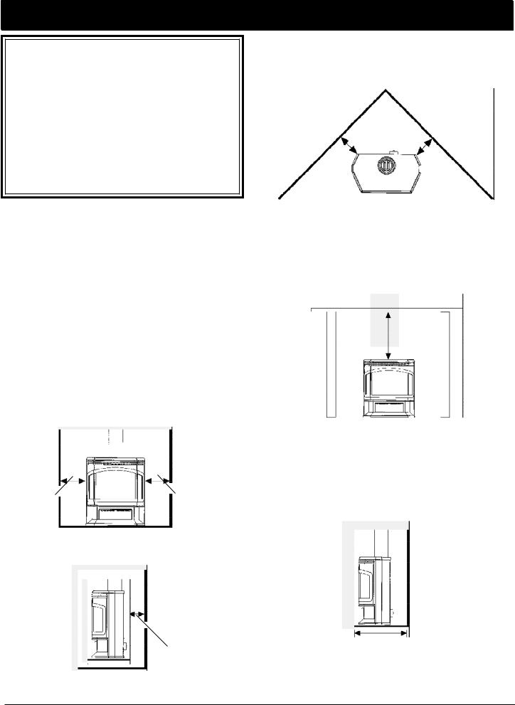
Clearances
The following clearances to combustibles must be observed:
Heater to left sidewall |
9" (230 mm) |
Heater to right sidewall |
9" (230 mm) |
Heater corner to walls |
4" (100 mm) |
Heater to back wall |
3" (75 mm) |
(measured from rear of heater to wall) |
|
Heater to alcove ceiling |
18" (460 mm) |
Maximum alcove depth |
14" (355 mm) |
In addition to the clearances mentioned previously, adequate accessibility clearance for servicing and proper operation mustbe maintained.
If this appliance is installed directly on carpeting, vinyl tile, or other combustible material other than wood flooring the appliance shall be installed on a metal or wood panel extending at least the full width and depth of the appliance.
9" (230 mm) |
9" (230 mm) |
Sidewall clearance
3" (75 mm)
Clearance to back wall
|
mm) |
4" |
(100 |
|
4" (100 mm)
Clearance from corner of unit to walls.
18" (460 mm)
Clearance to alcove ceiling.
14" (355 mm)
Maximum alcove depth
4
VENTING
Use Only Approved Venting
The Clarity Direct Vent Gas Heater has been tested and is listed for installation with Simpson Duravent GS venting components. The Simpson Duravent GS warranty will be voided, and serious fire, health, or other safety hazards may result from any of the following actions:
•Installation of any damaged DuraventGS component.
•Unauthorized modification oftheDuraventGS System.
•Installation ofany componentpartnotmanufactured or
approved by Simpson Duravent.
•Installation otherthan asinstructed bySimpson Duravent and the appliance manufacturer.
Consult your local building codes before beginning the installation, and follow the manufacturer's instructions exactly. The following Simpson Duravent GS 4"X 65/8" venting components are approved for use with the Clarity Direct Vent Gas Heater.
SIMPSON DURA-VENTCOMPONENTNO.
Basic Termination Kit ....................................................... |
|
970 |
Horizontal Termination Kit A........................................... |
|
971 |
VerticalTermination Kit A................................................. |
|
973 |
Horizontal Square Termination Cap................................. |
|
984 |
VerticalTermination Cap ................................................... |
|
983 |
Snorkel Termination Cap, 36" Vertical Rise..................... |
981 |
|
Snorkel Termination Cap, 14" Vertical Rise..................... |
982 |
|
Vinyl Siding Standoff ....................................................... |
|
950 |
Wall Thimble..................................................................... |
|
942 |
Round Ceiling Support/Wall Thimble Cover .................. |
940 |
|
Cathedral Ceiling Support Box ........................................ |
|
941 |
Storm Collar ...................................................................... |
|
953 |
Firestop Spacer................................................................. |
|
963 |
Adjustable RoofFlashing, 0/12-6/12 pitch ..................... |
943 |
|
Steep Roof Flashing, 7/12-12/12 pitch.......................... |
943S |
|
Wall Strap ......................................................................... |
|
988 |
Designer Series Trim Kits .......................... |
3951,3952,3953, |
|
|
3960,3961,3962 |
|
High WindVertical Termination Cap ............................... |
|
991 |
Low Profile Termination Cap............................................ |
|
980 |
DIRECT VENTPIPE LENGTHS |
|
|
DURA-VENTCOMPONENTNO. |
|
|
GALVANIZED |
BLACK |
|
6" length |
NA |
908B |
9" length |
NA |
907B |
12" length |
906 |
906B |
24" length |
904 |
904B |
36" length |
903 |
903B |
48" length |
902 |
902B |
11-14 5/8" Adjustable |
- |
911B |
45° Elbow |
945 |
945B |
90° Elbow |
990 |
990B |
The Clarity Direct Vent should be installed with no more than 12 joints and 2 elbows. The elbows may be either 45° or 90°.
The Clarity Direct Vent must not be connected to a chimney flue serving any other appliance.
WARNING: The flow of ventilation air must not be obstructed.
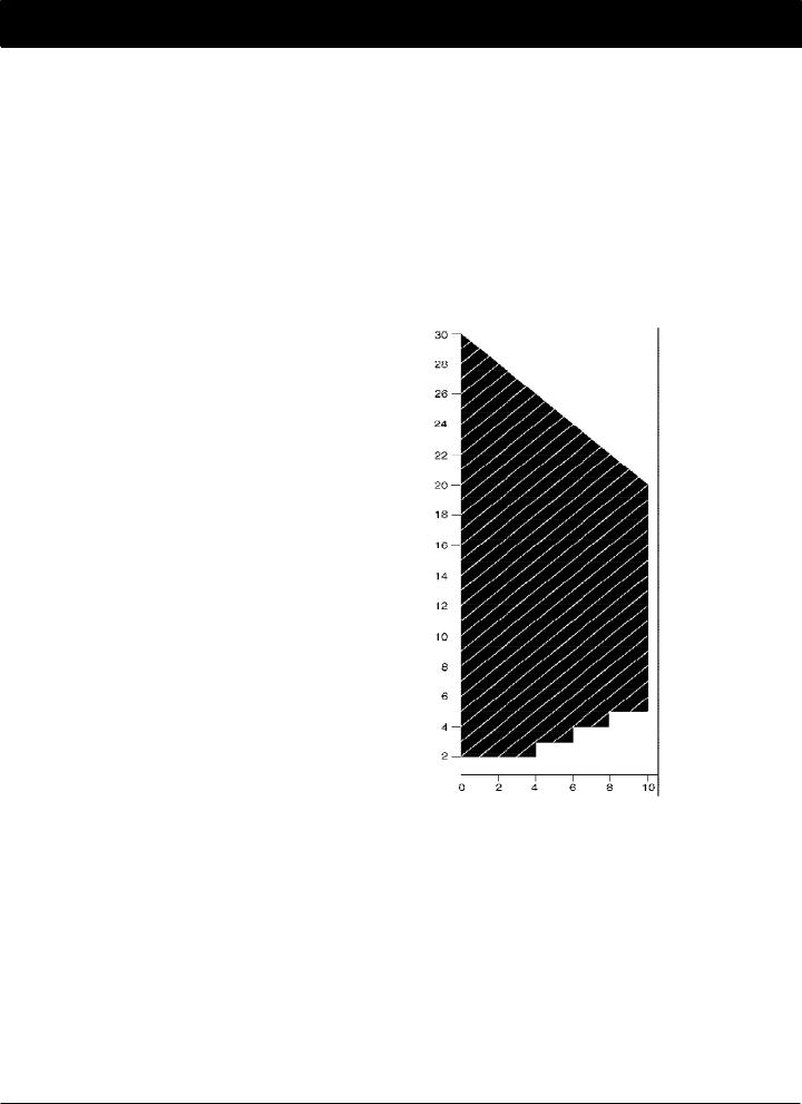
Horizontaland Vertical Venting Requirements
The maximum horizontal run allowed for the Clarity Direct Vent is 10 feet. The maximum vertical rise and maximum total vent length is 30 feet. The horizontal and vertical lengths of venting must fall within the shaded portion of the
chart below: |
|
Restrictor plates supplied |
by Harman |
(Part No. G218) may be added in straight vertical installations only. For each 10' of vertical rise above the first 10', one restrictor plate may be added. No more than two restrictor plates may be used.
For venting systems that utilize one or two elbows (either 45° or 90°), restrictor plates
should not be used.
For the ClarityDirect Vent, the vent/ air intake termination clearances above the high side of an angled roof are as follows:
Vertical (feet)rise
Horizontal run (feet) |
|
|
Roof Pitch |
Feet |
Meters |
Flat to 6/12 |
1 |
0.3 |
7/12 to 9/12 |
2 |
0.6 |
10/12 to 12/12 |
4 |
1.2 |
13/12 to 16/12 |
6 |
1.8 |
17/12 to 21/12 |
8 |
2.4 |
5
VENTING
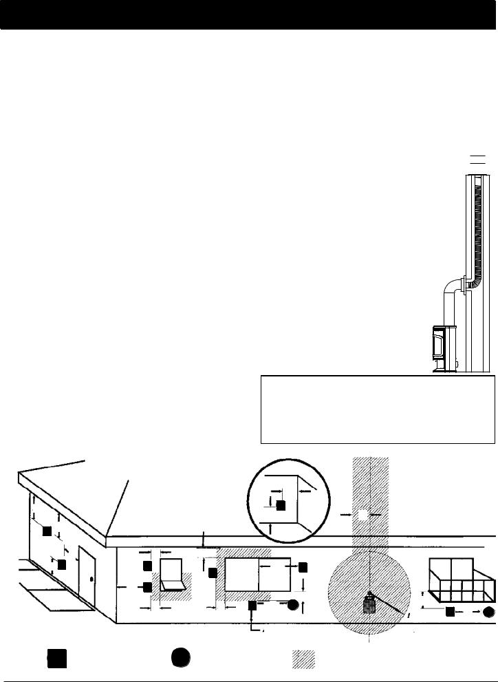
Requirements for Terminating the Venting
WARNING: Venting terminals must not be recessed into a wall or siding.
In addition, the following must be observed:
A.The clearance above grade, or a veranda, porch, deck or balcony must be a minimum of 12" (30 cm).1
B.The clearance to a window or door that may be opened must be a minimum of 12" (30 cm).1
C.A 12" (30 cm) clearance to a permanently closed window is recommended to prevent condensation on the window.
D.The vertical clearance to a ventilated soffit located above the terminal within a horizontal distance of 2 feet (60 cm) from the center-line of the terminal must be a minimum of 18" (46 cm).
E.The clearance to an unventilated soffit must be a minimum of 12" (30 cm).
F.The clearance to an outside corner is 9" (23 cm).
G.The clearance to an inside corner is 12" (30 cm).
H.A vent must not be installed within 3 feet (90 cm) above a meter/regulator assembly when measured from the horizontal center-line of the regulator.1
I.The clearance to service regulator vent outlet must be a minimum of 6 feet (1.8 m).1
J.The clearance to a non-mechanical air supply inlet to the building or the combustion air inlet to any other appliance must be a minimum of 12 feet (30 cm).1
K.The clearance to a mechanical air supply inlet must be a minimum of 6 feet (1.8 m).1
L.The clearance above a paved sidewalk or a paved driveway located on public property must be a minimum of 7 feet (2.1 m).1,2
M.The clearance under a veranda, porch, deck or balcony must be a minimum of 12 inches (30 cm).1,3
1As specified in CAN 1B1-149 Installation Codes (currend edition). Note: local codes or regulations may require different clearances.
2A vent shall not terminate directly above a side-walk or paved driveway which is located between two single family dwellings and serves both dwellings.
3Only permitted if veranda, porch, deck, or balconyis fully open on a minimum of 2sides beneath the floor.
Connecting To An Existing Chimney
The Clarity may be connected to an existing ma- 
 sonry chimneyby using aSimpson Dura-Vent con-


 version kit #934.
With this kit and a 4"flex linner in the chimney the flue gases exit through the 4" linner and the outside air comes down the chimney in the space between the chimney and the linner. This method allows you to install the Clarity your chimney and still get the added efficiencyprovided by direct venting.
The use of an existing chimneyas an
air intake is not covered under the ANSI Z21.50-1996. CGA 2.22-M96test methods andthe resulting ITS/WHI product certfication: The code AuthorityHaving Jurisdictionmust be consulted prior to proceeding.
I ns ide
Corner
Det ail
G
D |
V |
|
A |
||
|
V |
E |
|
|
|
B |
|
C |
|
L V |
V |
Fixed |
|
|
|
Closed |
|
F |
V |
Op enab le |
|
|
B
V |
|
B |
Openable |
Fixed |
|
|
|
Closed |
H
V |
|
|
V J |
B |
B |
B |
A |
|
|
|
M
V |
K |
A |
V |
= Vent terminal |
6 |
|
|
A |
A = Air supply inlet |
= Area where terminal is not permitted |

ASSEMBLY
The Clarity is shipped from the factory with the log set packed inside the firebox. To prepare the stove for installation, the log set must be unpacked, the appropriate burner system module for either natural gas or propane installed, and the logs installed.
Removing the Glass Front
NOTE: The glass front is heavy. Be prepared for its weight when lifting it to avoid damage during removal.
The wing doors on each side are held closed by magnets. Push on each door to open it. Loosen the wing nut on each of the two spring-loaded levers. Grasp each lever and push to the rear to disengage the front. To keep the levers in the disengaged position, tighten the wing nuts. Lift the glass front slightly and remove it from the stove. Set the glass aside in a safe place where it will not be damaged.
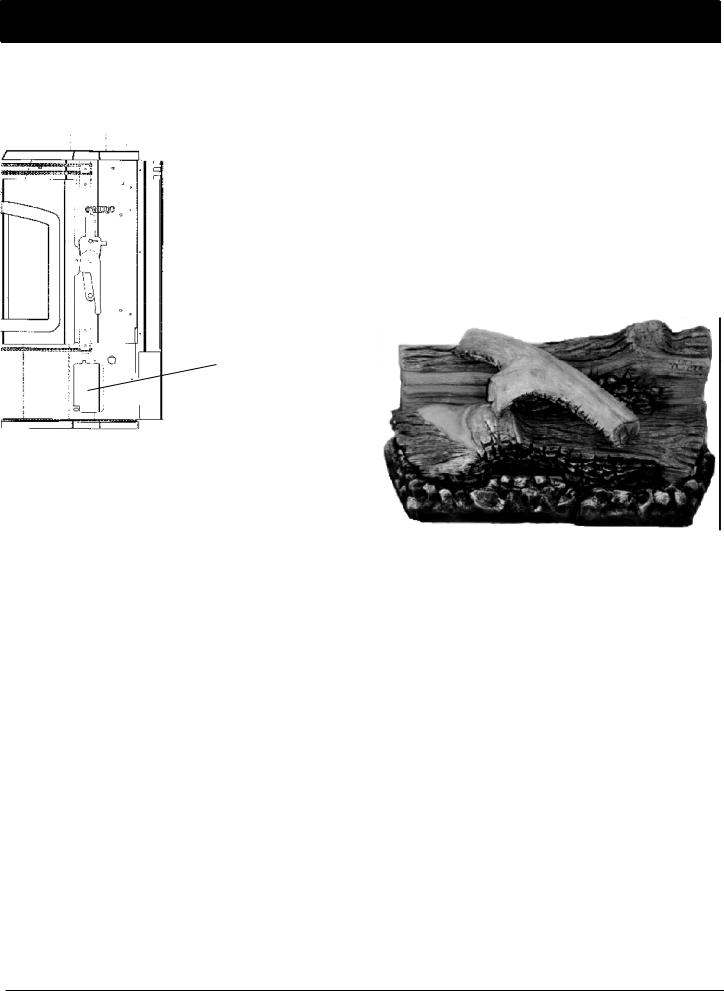
Remove and Unwrap the Log Set
As shown in the photo in the right column, the log set consists of a back log (1), a center log that has a pilot-view- ing port in the left end (2), two ember strips (3), and a branch that rests on top (4).
In addition, there are two side brick panels and a back brick panel.
The log set components are shipped from the factory individually wrapped and packed inside the stove. Take them out of the stove, then carefully remove the wrapping. Handle the logs gently as they may be damaged easily.
1
|
2 |
3 |
4 |
3 |
 The front is released when spring-loaded levers on the left and right sides are pushed to the rear
WARNING: Do not abuse the Clarity's glass by striking, slamming, or similar trauma. Do not operate the Clarity Gas Heater with the glass panel removed, cracked or broken. Use only glass supplied by Harman and approved for use with this heater. Do not use substitute materials. Replacement of the panel should be done by a licensed or qualified service person.
Installing the Burner System Module
The burner system module may be installed into the firebox as an integrated unit, and it may help to have an assistant who can assist in guiding the components into position and in making sure that themodule does not siton anywiring components.
Hold the module at a slight angle, then lower it through the openingand rotate upright until it is in position.
Reach underneath and install one of the wing nuts, finger tight. Then check to see that the module is seated correctly.
Asealing gasket affixed to the bottom of the module's base plate will cause the log support plate to be elevated slightly above the plane of the firebox bottom plate. When the two wing nuts are tightened, this gasket will be compressed and a correct fit will be indicated bythelog support plate becoming flush with the bottom of the firebox.
Install wing nut |
|
on threaded stud |
7 |
ASSEMBLY
With the module installed and secured, reach through the side access ports and plug in the electrical connections. (Two AMP Mate-N-Lok connectors).
The two electrical connectors may be reached through the side access port
Installthe Branch
Orient the branch with the forked end toward the left rear of the stove and slip it over the two locator pins, one on top of the back logand the other on the top of the center log.
Secure the Glass Front
NOTE: The glass front is heavy. Lift it carefully to prevent damage. Center the glass on the opening and suspend it in place by placing the the tab hooks over the top edge of the opening. Loosen the wing nuts that hold the spring-loaded levers in place. Press the glass slightly against the stove to confirm that it seats properly, then press it firmlyagainst the front while pulling the levers forward to engage them. Tighten the wing nuts.
Install the Back Log and Back Brick Panel
These two components are installed as a single piece. Rest the back brick panel on the shelf located on the back side of the back log, and center it. Holding the two pieces as
a single unit, tilt the top forward slightly and manuever it over the top of the rear burner—taking care that the top
corners clear the front opening. Place it snugly against the back wall and center it.
Installthe Side Brick Panels
These slide into place along each side and are held by friction. The notch in each panel faces the back. Install one side, and then the other.
Install the Ember Strips
The ember strips rest against the front of the firebox and should fit snugly. Guide them toward you and to the outside until theyfit snugly. Check the air slot in the inside of the ember strips to confirm that they do not obstruct it.
Install the Center Log
The center log goes all the way to the back and should be centered. When properly positioned, there should be an even gap alongthe front of the center burner in the cavity in the log. A small portion of the log support frame will be revealed.
The center log has a round viewing port in the left end through which the pilot can be observed.
The complete log set with all logs in the correct position.
8
 Loading...