


Installation & Operating Manual
P43 Pellet Stove Owners Manual
“Ce manuel est disponible en Français sur demande” |
R1 |
SAFETY NOTICE
Please read this entire manual before you install and use your new room heater. Failure to follow instructions may result in property damage, bodily injury, or even death.
FOR USE IN THE U.S. AND CANADA. SUITABLE FOR INSTALLATION IN MOBILE HOMES.
IF THIS HARMAN STOVE IS NOT PROPERLY INSTALLED, A HOUSE FIRE MAY RESULT. FOR YOUR SAFETY, FOLLOW INSTALLATION DIRECTIONS.
CONTACT LOCAL BUILDING OR FIRE OFFICIALS ABOUT RESTRICTIONS AND INSTALLATION INSPECTION REQUIREMENTS IN YOUR AREA.
Contact your local authority (such as municipal building department, fire department, fire prevention bureau, etc.) to determine the need for a permit.
Cette guide d'utilisation est disponible en francais. Chez votre concessionnaire de Harman
Stove Company. |
R1 |
|
|
|
|
|
save these instructions. Manual Item# 3-90-04301 |
|
|
Stove Pellet P43
LISTED PELLET FUEL BURNING ROOM HEATER APPAREIL DE CHAUFFAGE CATALOGUÉ DE |
||
MODÈLE POUR BRÛLER DES BOULETTES COMBUSTIBLES. |
||
DO NOT REMOVE THIS LABEL. |
MODEL / MODÈLE: "PP 38+" / "P43" |
NE PAS ENLEVER CETTE ÉTIQUETTE. |
W/N 02531 |
WHI - |
|
INSTALL WITH MINIMUM CLEARANCES TO WALLS AS |
|||
TESTED TO : UL 1482 ASTM E1509 |
|
|
||||
|
|
SHOWN / INSTALLER AVEC LES DISTANCES MINIMUM |
||||
OREGON 814-23-900 |
|
|
||||
BAR CODE LABEL |
|
DE SECURITÉ COMME INDIqUÉ. |
||||
ULC-S627 |
|
|||||
|
|
SIDEWALL-BACkWALL |
SIDEWALL-BACkWALL |
|||
WH-PN 025 |
|
|
||||
|
|
|
INSTALLATION WITH |
INSTALLATION WITHOUT |
||
TEST DATE: JUNE 1997 |
|
|
|
SIDE SHIELDS |
SIDE SHIELDS |
|
MINIMUM CLEARANCES |
WITHOUT |
WITH |
|
2"/51mm |
2"/ 51mm |
|
TO COMBUSTIBLES: |
SIDE SHIELDS |
SIDE SHIELDS |
|
|
|
|
SIDEWALL TO STOVE |
16" |
10" |
|
|
|
|
BACKWALL TO STOVE |
2" |
2" |
|
|
16" |
|
CEILING TO STOVE TOP |
18" |
18" |
|
10" |
406mm |
|
STOVE CORNER TO DIAGONAL WALL |
9" |
9" |
|
254mm |
|
|
PREVENT HOUSE FIRES, OPERATE WITH VIEWING & ASH DOOR CLOSED. |
DISTANCES AUX MURS |
DISTANCES AUX MURS |
||||
UNIT MUST BE PLACED ON A NON-COMBUSTIBLE FLOOR PROTECTOR EXTENDING |
||||||
LATÉRAL ET ARRIÈRE AVEC |
LATÉRAL ET ARRIÈRE SANS |
|||||
6" TO THE FRONT, 6" TO SIDES AND 1" TO REAR. MEASURE FRONT FROM GLASS. |
PROTECTIONS MURALES |
PROTECTIONS MURALES |
||||
EXHAUST TYPE: LISTEDTYPE LOR PLVENTINSTALLEDTO VENTMANUFACTURER'S |
FLOOR PROTECTOR |
CORNER INSTALLATION 9" WITH |
||||
INSTRUCTIONS AND LOCAL BUILDING CODES. |
|
|
MINIMUM SIzE |
OR WITHOUT SIDE SHIELDS |
||
ELECTRICAL RATING: 6 AMPS, 120 VOLTS, 60 HERTZ |
|
|
1"/25mm |
|
||
|
|
|
|
|||
FUEL: PELLETIZED OR BIOMASS |
|
|
|
|
9" / 229mm |
|
INSTALL AND USE ONLY IN ACCORDANCE WITH MANUFACTURER'S INSTALLATION |
|
|
|
|||
AND OPERATING INSTRUCTIONS. CONTACT LOCAL BUILDING OR FIRE OFFICIALS |
6" / |
6" / |
|
|||
ABOUT RESTRICTIONS & INSTALLATION INSPECTION IN YOUR AREA. |
152mm |
152mm |
|
|||
EPA EXEMPT PER 40 CFR 60.534, METHOD 28A. |
|
|
|
/ 9" |
||
APPROVED FOR USE IN MOBILE HOMES. |
|
|
|
6" / |
229mm |
|
INPUT RATING: .75 TO 5.5 LBS PER HOUR. |
|
|
152mm |
|||
|
|
|
|
TAILLE MINIMALE |
INSTALLATION EN ANGLE 229mm |
|
DO NOT CONNECT THIS UNIT TO A CHIMNEY SERVING ANOTHER APPLIANCE. |
DE LA PROTECTION DE SOL. |
|||||
AVEC OU SANS PROTECTIONS |
||||||
NE PAS CONNECTER CET APPAREIL À UNE CHEMINÉE SERVANT UN AUTRE |
|
|
MURALES |
|||
APPAREIL. |
|
|
|
|
|
|
Manufactured By / Fabrique Par:
352 MOUNTAIN HOUSE ROAD
HALIFAX, PA 17032
ESPACES LIBRES MINIMUM |
SANS LES |
AVEC LES |
PROTECTEURS |
PROTECTEURS |
|
DES MATÉRIAUX COMBUSTIBLES: |
DE CÔTÉ |
DE CÔTÉ |
DU MÛR DE CÔTÉ AU POÊLE |
406 mm |
254 mm |
DU MÛR ARRIÈRE AU POÊLE |
51 mm |
51 mm |
DU PLAFOND AU DESSUS DU POÊLE |
457 mm |
457 mm |
DU COIN DU POÊLE AU MÛR DIAGONAL |
229 mm |
229 mm |
PRÉVENIR LES FEUX DE MAISONS. OPÉRER SEULEMENT AVEC LA PORTE D'OUVERTURE ET LA PORTE DES CENTRES FERMÉES. L'APPAREIL DOIT ÊTRE PLACÉSURUNPLANCHERPROTECTEURINCOMBUSTIBLE,CELUI-CIS'ÉTENDANT DE 152 mm EN AVANT, DE 152 mm DES CÔTÉS ET D 25 mm DE L'ARRIÈRE.
SORTE D'ÉCHAPPEMENT: VENTILATEUR DE TYPE L OU PL INSTALLÉ SELON LES INSTRUCTIONS DU FABRICANT ET SELON LES CODES LOCAUX DE LA CONSTRUCTION.
PUISSANCE ÉLECTRIqUE: 6 AMPS, 120 VOLTES, 60 HERTZ COMBUSTIBLE: DE BOULETTES COMBUSTIBLES OU BIOMASSES.
INSTALLER ET UTILISER SELON LES INSTRUCTIONS D'INSTALLATION ET D'OPÉRATION DE FABRICANT. CONTACTER LE BUREAU DE LACONSTRUCTION OU LE BUREAU DES POMPIERS AU SUJET DES RESTRICTIONS ET DES INSPECTIONS D'INSTALLATION DANS VOTRE VOISINAGE.
EXEMPTION EPA PAR 40 CFR 60.534, DE MÉTHODE 28a APPROUVÉ POUR L'USAGE DANS LES MAISONS MOBILES PUISSANCE ESTIMÉE: .75 À 5.5 LBS PAR HEURE.
MADE IN USA |
P.N. 3-90-04300 |
Introduction
The P43 Pellet Stove has huge features in a small package, giving you 0 to 43,000 BTU when you need it, automatically. You basically need to set your desired room temperature and fill the hopper. With the P43 you will notice even heat throughout your zone and a level of convenience you never thought possible.
The P43 epitomizes the capability of Harman Pellet Stoves, taking advantage of Harman’s 20+ years of pellet stove design, technology and manufacturing. This 43,000 BTU stove has the smartest controls coupled with minimal maintenance. The P43's output is managed by a microprocessor that senses the room temperature and the fire temperature with tiny thermistor probes and then determines the best feed rate for your heating demand. This improved and smarter control also has a diagnostic port which allows a service representative to attach an external display showing live working data for ease in troubleshooting.
The platinum combination is Harman’s Patented Feeder & Burn Pot, and ESP Control which have been developed to their highest state. These features work together to allow amazing heat output with little regard for fuel quality.
Serial #:
This label is located on the back of the unit.
Please copy the Serial Number for future reference.
LISTED PELLET FUEL BURNING ROOM HEATER APPAREIL DE CHAUFFAGE CATALOGUÉ DE |
Manufactured By / Fabrique Par: |
||
MODÈLE POUR BRÛLER DES BOULETTES COMBUSTIBLES. |
|
||
DO NOT REMOVE THIS LABEL. |
/ MODÈLE: "PP 38+" / "P43" |
NE PAS ENLEVER CETTE ÉTIQUETTE. |
|
W/N 02531 |
WHI - |
|
|
|
|
|
|
|
|
|
|
TESTED TO : UL 1482 ASTM E1509 |
|
|
|
|
|
|
|
|
|
|
|
OREGON 814-23-900 |
|
|
|
|
|
|
|
|
|
|
|
ULC-S627 |
|
|
BAR CODE LABEL |
|
|
||||||
WH-PN 025 |
|
|
|
|
|
|
|
|
|
|
|
|
|
|
|
|
|
|
|
|
|
|
|
TEST DATE: JUNE 1997 |
|
|
|
|
|
|
|
|
|
|
|
MINIMUM CLEARANCES |
|
WITHOUT |
WITH |
||||||||
TO COMBUSTIBLES: |
|
SIDE SHIELDS |
SIDE SHIELDS |
||||||||
SIDEWALL TO STOVE |
16" |
10" |
|
|
|
|
|
|
|||
BACKWALL TO STOVE |
2" |
2" |
|
|
|
|
|
|
|
||
CEILING TO STOVE TOP |
18" |
18" |
|
|
|
|
|
|
|||
STOVE CORNER TO DIAGONAL WALL |
9" |
9" |
|
|
|
|
|
|
|
||
PREVENT HOUSE FIRES, OPERATE WITH VIEWING & ASH DOOR CLOSED.
UNIT MUST BE PLACED ON A NON-COMBUSTIBLE FLOOR PROTECTOR EXTENDING 6" TO THE FRONT, 6" TO SIDES AND 1" TO REAR. MEASURE FRONT FROM GLASS. EXHAUST TYPE: LISTEDTYPE LOR PLVENTINSTALLEDTO VENTMANUFACTURER'S INSTRUCTIONS AND LOCAL BUILDING CODES.
ELECTRICAL RATING: 6 AMPS, 120 VOLTS, 60 HERTZ FUEL: PELLETIZED OR BIOMASS
INSTALL AND USE ONLY IN ACCORDANCE WITH MANUFACTURER'S INSTALLATION AND OPERATING INSTRUCTIONS. CONTACT LOCAL BUILDING OR FIRE OFFICIALS ABOUT RESTRICTIONS & INSTALLATION INSPECTION IN YOUR AREA.
EPA EXEMPT PER 40 CFR 60.534, METHOD 28A. APPROVED FOR USE IN MOBILE HOMES. INPUT RATING: .75 TO 5.5 LBS PER HOUR.
DO NOT CONNECT THIS UNIT TO A CHIMNEY SERVING ANOTHER APPLIANCE. NE PAS CONNECTER CET APPAREIL À UNE CHEMINÉE SERVANT UN AUTRE APPAREIL.
INSTALL WITH MINIMUM CLEARANCES TO WALLS AS SHOWN / INSTALLER AVEC LES DISTANCES MINIMUM DE SECURITÉ COMME INDIqUÉ.
SIDEWALL-BACkWALL |
|
|
INSTALLATION WITH |
|
SIDE SHIELDS |
|
2"/51mm |
|
10" |
|
254mm |
DISTANCES AUX MURS |
|
LATÉRAL ET ARRIÈRE AVEC |
|
PROTECTIONS MURALES |
|
|
FLOOR PROTECTOR |
|
MINIMUM SIzE |
|
1"/25mm |
6" / |
6" / |
152mm |
152mm |
 6" / 152mm
TAILLE MINIMALE
DE LA PROTECTION DE SOL.
SIDEWALL-BACkWALL |
INSTALLATION WITHOUT |
SIDE SHIELDS |
2"/ 51mm |
16" |
406mm |
DISTANCES AUX MURS |
LATÉRAL ET ARRIÈRE SANS |
PROTECTIONS MURALES |
CORNER INSTALLATION 9" WITH OR WITHOUT SIDE SHIELDS
9" / 229mm |
229mm / 9" |
INSTALLATION EN ANGLE 229mm |
AVEC OU SANS PROTECTIONS |
MURALES |
352 MOUNTAIN HOUSE ROAD
HALIFAX, PA 17032
ESPACES LIBRES MINIMUM |
SANS LES |
AVEC LES |
PROTECTEURS |
PROTECTEURS |
|
DES MATÉRIAUX COMBUSTIBLES: |
DE CÔTÉ |
DE CÔTÉ |
DU MÛR DE CÔTÉ AU POÊLE |
406 mm |
254 mm |
DU MÛR ARRIÈRE AU POÊLE |
51 mm |
51 mm |
DU PLAFOND AU DESSUS DU POÊLE |
457 mm |
457 mm |
DU COIN DU POÊLE AU MÛR DIAGONAL |
229 mm |
229 mm |
PRÉVENIR LES FEUX DE MAISONS. OPÉRER SEULEMENT AVEC LA PORTE D'OUVERTURE ET LA PORTE DES CENTRES FERMÉES. L'APPAREIL DOIT ÊTRE PLACÉSURUNPLANCHERPROTECTEURINCOMBUSTIBLE,CELUI-CIS'ÉTENDANT DE 152 mm EN AVANT, DE 152 mm DES CÔTÉS ET D 25 mm DE L'ARRIÈRE.
SORTE D'ÉCHAPPEMENT: VENTILATEUR DE TYPE L OU PL INSTALLÉ SELON LES INSTRUCTIONS DU FABRICANT ET SELON LES CODES LOCAUX DE LA CONSTRUCTION.
PUISSANCE ÉLECTRIqUE: 6 AMPS, 120 VOLTES, 60 HERTZ COMBUSTIBLE: DE BOULETTES COMBUSTIBLES OU BIOMASSES.
INSTALLER ET UTILISER SELON LES INSTRUCTIONS D'INSTALLATION ET D'OPÉRATION DE FABRICANT. CONTACTER LE BUREAU DE LACONSTRUCTION OU LE BUREAU DES POMPIERS AU SUJET DES RESTRICTIONS ET DES INSPECTIONS D'INSTALLATION DANS VOTRE VOISINAGE.
EXEMPTION EPA PAR 40 CFR 60.534, DE MÉTHODE 28a APPROUVÉ POUR L'USAGE DANS LES MAISONS MOBILES PUISSANCE ESTIMÉE: .75 À 5.5 LBS PAR HEURE.
MADE IN USA |
P.N. 3-90-04300 |
Please read this entire manual before you install and use your new room heater. Failure to follow instructions may result in property damage, bodily injury, or even death.
352 Mountain House Road
Halifax, PA 17032
Table of Contents
Installation |
5 |
Venting |
7 |
ESP Control |
14 |
Automatic Operation |
15 |
Manual Operation |
18 |
Low Draft Voltage Adjustment |
20 |
Room Sensor |
21 |
Maintenance |
22 |
Trouble Shooting |
26 |
Feeder Parts |
27 |
Specifications |
28 |
Options |
29 |
Wiring Diagram |
30 |
Parts List |
31 |
Warranty |
32 |
P43 Pellet Stove
IMPORTANT NOTES
DO NOT INSTALL A FLUE DAMPER IN THE EXHAUST VENTING SYSTEM OF THIS UNIT.
DO NOT CONNECT THIS UNIT TO A CHIMNEY FLUE SERVING ANOTHER APPLIANCE.
SPECIAL NOTE:
Due to fly ash buildup, it is strongly recommended that you have your stove professionally cleaned and serviced annually. This includes all parts of the stove, and the entire venting system.
CAUTION
Always be sure there is no unburned fuel in the ash pan prior to lighting a fire. This will cause smoke and soot and other unwanted results.
Installation and repair of this Harman stove should be done by a qualified service person. We recommend that the stove be inspected before use and at least annually by a qualified service person. Periodic cleaning is required throughout the heating season and at the end of each winter for the stove to work efficiently. See cleaning instructions on page 22.
WARNING
M o b i l e / M a n u fa c t u r e d H o m e S ta n d a r d s D o N o t A l l o w Installation In Rooms Designated For Sleeping.
CAUTION
THE STRUCTURAL INTEGRITY OF THE MOBILE HOME FLOOR, WALL, AND CEILING/ROOF MUST BE MAINTAINED.
Mobile home installation should be done in accordance with the Manufactured Home and Safety Standard (HUD), CFR 3280, Part 24.
CAUTION
Keep combustible materials (such as grass, leaves, etc.) at least 3 feet away from the flue outlet on the outside of the building.
P43 Pellet Stove
Assembly and Installation
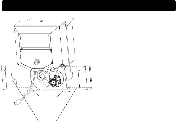
|
Shipping Bolts |
|
|
Note: These same holes |
|
|
are used for securing the |
|
Fig. 1 |
stove in mobile home |
|
installation. |
||
|
||
|
Rear Cover |
|
|
Panels |
Unpacking
The P43 is bolted (1/4 x 1" hex head bolts) to the skid to prevent movement during shipping.
To free the stove from the skid you must remove the hold-down bolts in the rear of the pedestal base.
Removing rear cover panels
The rear cover panels are secured to the stove with three bolts each. Two ot the bolts need only be loosened, not removed, to remove the panels. It is recommended that the rear covers are installed after the unit is in place and the vent pipe is installed, to prevent contact with hot or moving parts.
Firebrick
Install the firebrick horizontally on the angle bracket above the burnpot.
Flame Guide
Install the cast iron flame guide on top of the burn pot. Make sure that the flame guide is fully seated on the vertical sides of the burn pot and that the back of the guide rests against the body of the stove.
INSTALL EXHAUST VENT AT CLEARANCES SPECIFIED BY THE MANUFACTURER. Most pellet vent pipe requires a minimum of 3" of clearance to combustible materials allthough some can be installed at 1" clearance.
P43 Pellet Stove
Installation
Installing
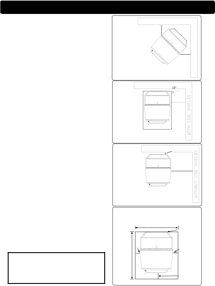
Place the stove on a noncombustible floor protector that extends a minimum of 6 inches to the front, (measured from the glass) 6 inches to the sides and 1 inch to the rear of the hopper. In some places, it is required that floor protection be installed under any horizontal venting.The minimum floor protector material is 20 gauge sheet metal. Other floor protector materials are ceramic tile, stone, brick, etc.
Place the stove away from combustible walls at least as far as shown in Figures 3,4 and 5. Note the difference in side wall clearance with and without side shields.
Note that the clearances shown are minimum for safety but do not leave much room for access when cleaning or servicing.
Connect the power cord to a 120 V.A.C. 60Hz grounded receptacle. (A surge protector is recommended to protect the circuit board.) If the voltage entering your home is below 116 volts your stove may not work properly. Also be sure that the polarity of the outlet that the stove is plugged into is correct.
Prior to installing the flue pipe, connect a draft meter.
(The draft meter must have a minimum range of 0-
.5.)Record the first reading. Connect flue pipe to stove and be sure all doors and windows in the home are closed. Record the second draft reading_______. If the second reading is more than .05" lower than the first reading, check for possible restrictions or the need for outside air (see page 9). For more information on the draft test procedure, refer to Page 20.
Mobile Home Installation
When installing this unit in a mobile home, several requirements must be followed:
1.The unit must be bolted to the floor. This can be done with 1/4" lag screws through the 2 holes in the base plate.
2.The unit must also be connected to outside air. See page 9.
3.Floor protection and clearances must be followed as shown.
4.Unit must be grounded to the metal frame of the mobile home.
CAUTION: This appliance must be vented to the outside.
Due to high temperatures, the stove should be placed out of traffic and away from furniture and draperies.
Children and adults should be alerted to the hazards of high surface temperatures and should stay away to avoid burns to skin and/or clothing.
Young children should be carefully supervised when they are in the same room as the stove.
Clothing and other flammable materials should not be placed on or near this unit.
WARNING
Mobile/Manufactured Home Standards Do Not Allow Installation In Rooms Designated For Sleeping.
9"
9"
9" With or Without Side Shields
Fig. 3
10"
Fig. 4
2"
16"
Fig. 5
Floor Protection must be 2 inches to each side, 6 inches to the front, and 1 inch to the back of the stove. Floor Protector minimum: 32½" wide x 33" deep.
minimum33" |
|
1" |
|
6" |
6" |
||
|
|||
|
|
||
|
|
6"(measured |
|
|
|
from glass) |
P43 Pellet Stove

Venting
Requirements for Terminating the Venting
WARNING: Venting terminals must not be recessed into a wall or siding.
NOTE: Only approved pellet vent pipe, wall passthroughs, and fire stops should be used when venting through combustible materials.
NOTE: Always take into consideration the effects of the prevailing wind direction or other wind currents that may cause flyash and/or smoke when placing the termination of the vent.
In addition, the following must be observed:
A.The clearance above grade must be a minimum of 18".1
B.The clearance to a window or door that may be opened must be a minimum of 48" to the side, 48" below the window/door, and 12" above the window/door.1
(with outside air installed, 18” to the side or below)
C.A 12" clearance to a permanently closed window is recommended to prevent condensation on the window.
D.The vertical clearance to a ventilated soffit located above the terminal within a horizontal distance of 2 feet (60 cm) from the center-line of the terminal must be a minimum of 18".
E.The clearance to an unventilated soffit must be a minimum of 12".
F.The clearance to an outside corner is 11" from center of pipe.
G.The clearance to an inside corner is 12".
H.A vent must not be installed within 3 feet (90 cm) above a gas meter/regulator assembly when measured from the horizontal center-line of the regulator.1
I.The clearance to service regulator vent outlet must be a minimum of 6 feet.1
J.The clearance to a non-mechanical air supply inlet to the building or the combustion air inlet to any other appliance must be a minimum of 48”.1
K.The clearance to a mechanical air supply inlet must be a minimum of 10 feet.1
(with outside air installed, 6 feet )
L.The clearance above a paved sidewalk or a paved driveway located on public property must be a minimum of 7 feet.1,2
M. The clearance under a veranda, porch, deck or balcony must be a minimum of 12 inches.1,3
NOTE: The clearance to vegetation and other exterior combustibles such as mulch is 36” as measured from the center of the outlet or cap. This 36” radius continues to grade or a minimum of 7 feet below the outlet.
1Certain Canadian and/or Local codes or regulations may require different clearances.
2A vent shall not terminate directly above a sidewalk or paved driveway which is located between two single family dwellings and serves both dwellings.
3Only permitted if veranda, porch, deck, or balcony is fully open on a minimum of 2 sides beneath the floor.
NOTE: Where passage through a wall, or partition of combustible construction is desired, the installation shall conform to CAN/CSA-B365. (if in Canada)
V = Vent terminal
P43 Pellet Stove
Venting
IMPORTANT NOTICE
Approved Pellet Vent Pipe Such As, Type "L"
Or "PL", Must Be Used.
+
-
+
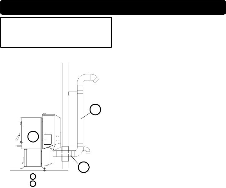
+ = Positive Static Pressure - = Negative Static Pressure Fig. 7
Venting
A combustion blower is used to extract the combustion gases from the firebox. This causes a negative pressure in the firebox and a positive pressure in the venting system as shown in Fig. 7. The longer the vent pipe and more elbows used in the system, the greater the flow resistance. Because of these facts we recommend using as few elbows as possible and 15 feet or less of vent pipe. The maximum horizontal run should not exceed 48". If more than 15 feet of pipe is needed, the interior diameter should be increased from 3" to 4" because a larger pipe causes less flow resistance. Be sure to use approved pellet vent pipe wall and ceiling pass-through fittings to go through combustible walls and ceilings. The use of a starting collar is not always necessary. The first piece of pipe should be fastened securely with at least 2 fasteners to the flue collar of the stove. If a starting collar is used to attach the venting system to the stove, the starting collar must be sealed to the stove with high temp silicone caulking.
Vent Pipe
Pellet venting pipe (known as L or PL vent) is constructed of two layers with air space between the layers. This air space acts as an insulator and reduces the outside surface temperature to allow a clearance to combustibles of 1 to 3 inches. The sections of pipe lock together to form an air tight seal in most cases. However, in some cases a perfect seal is not achieved. For this reason and the fact that the P43 operates with a positive vent pressure we specify that the joints also be sealed with silicone. Aluminum tape can also be used for any joint that is 1ft. or more from the outlet of the stove.
We cannot emphasize enough, the importance of sealing every seam and joint in the venting system which is inside the home. Even the smallest pin hole can leak and when it does you will smell wood smoke or a creosote smell in the room. If this occurs check for leaks. Leaks are easiest to see during start-up. Alternatively you can use a smoke pellet to leak test the venting before lighting your first fire.
P43 Pellet Stove
Venting
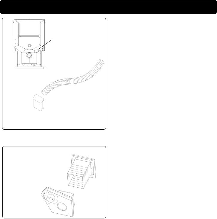
Outside air flex pipe goes here.
Flex pipe part#
1-00-08543 (25')
Inlet Cover part# 1-10-08542
Direct Vent Wall Passthrough Kit
(part #1-00-677077)
Outside Air
Here are four benefits of outside air:
1.Having air introduced from outside the living area boosts thermal efficiency. Because the make up air is not being drawn in through leaky windows or doors.
2.Outside air connection eliminates draft problems that can occur in tight homes.
3.Outside air connection reduces smoke spillage in the event of a power failure.
4.Outside air connection allows your vent termination to be as close as 18" from windows or doors.
Outside air is optional, except in mobile homes and where building codes require. The benefit of outside air is mainly noticed in small, very tight, houses.
To install outside air use 2 3/8" I.D. non-combus- tible flex pipe. There is a break-away hole on the rear panel of the P43 stove which must be removed before connecting the flex pipe. The pipe should be run outside and terminate to the side or below the vent pipe outlet so the flue outlet is more than 12" from the inlet cover. The maximum length run of this pipe is 15 feet. If a longer run is needed the size must be increased to 3". Inlet cover, part number 1-10-08542 should be used to keep birds, rodents, etc.out of the pipe.
You may choose to use the optional Direct Vent Wall Passthrough Kit (part #1-00-677077) which incorporates the venting passthrough and outside air inlet into one component.
HRV
When installing in a house with a Heat Reclaiming Ventilation System (HRV) be sure the system is balanced and is not creating a negative pressure in the house.
P43 Pellet Stove
Venting
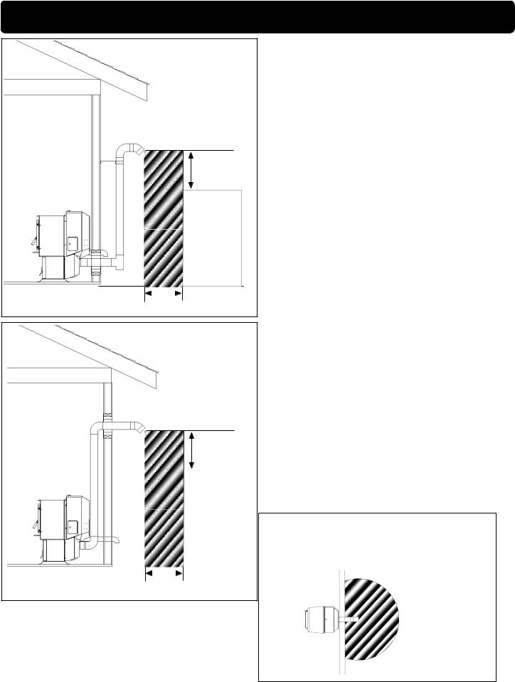
3 ft.
to combustibles
Fig. 8 |
|
|
|
|
|
|
|
||
|
3 ft. |
|||
|
to combustibles |
|||
#1 Preferred method
This method provides excellent venting for normal operation and allows the stove to be installed closest to the wall. Two inches from the wall is safe; however, four inches allows better access to remove the rear panel. The vertical portion of the vent should be three to five feet high. This vertical section will help provide natural draft in the event of a power failure. Note: Do not place joints within wall pass-throughs.
3 ft.
to combustibles
|
|
|
|
|
|
|
|
|
|
Fig. 9 |
|
3 ft. |
||
to combustibles |
||||
#2 Preferred method
This method also provides excellent venting for normal operation but requires the stove to be installed farther from the wall. The vertical portion of the vent should be three to five feet high and at least three inches from a combustible wall. This vertical section will provide natural draft in the event of a power failure.
If the stove is installed below grade be sure the vent termination is at least 18" above grade. The outlet must also be 1 foot from the house/building.
Note: Do not place joints within wall passthroughs.
CAUTION
Keep combustible materials (such as grass, leaves, etc.) at least 3 feet away from the flue outlet on the outside of the building.
12" min. wall to outlet
36" min clearance to any combustible material
10 P43 Pellet Stove
 Loading...