


SAVE THESE INSTRUCTIONS.
Owner's Manual
Installation and Operation
Model:
P35i
Pellet/Biomass
Fireplace Insert
#1-70-774195
#1-70-774235
NOTICE
DO NOT DISCARD THIS MANUAL
• Important operating and |
• Read, understand and |
• Leave this manual with |
maintenance instructions |
follow these instructions |
party responsible for use |
included. |
for safe installation and |
and operation. |
|
operation. |
|
Do |
Not |
|
|
Discard |
|
 WARNING
Please read this entire manual before installation and use of this fireplace insert room heater. Failure to follow these instructions could result in property damage, bodily injury or even death.
•Do not store or use gasoline or other flammable vapors and liquids in the vicinity of this or any other appliance.
•Do not overfire - If any external part starts to glow, you are overfiring. Reduce feed rate. Overfiring will void your warranty.
•Comply with all minimum clearances to combustibles as specified. Failure to comply may cause a house fire.
 WARNING
HOT SURFACES!
Glass and other surfaces are hot during operation AND cool down.
Hot, will cause burns.
•Do not touch glass until it is cooled
•NEVER allow children to touch glass
•Keep children away
•CAREFULLY SUPERVISE children in same room as fireplace.
•Alert children and adults to hazards of high temperatures.
High temperatures may ignite clothing or other flammable materials.
•Keep clothing, furniture, draperies and other flammable materials away.
CAUTION
Tested and approved for use with wood pellets and a mixture of shelled field corn and wood pellets only. Burning any other type of fuel will void your warranty.
CAUTION
Check building codes prior to installation.
•Installation MUST comply with local, regional, state and national codes and regulations.
•Consult local building, fire officials or authorities having jurisdiction about restrictions, installation inspection, and permits.
www.harmanstoves.com |
3-90-775 |
Rev; 7 |
August, 2011 |

P35i Fireplace Insert
Hearth & Home Technologies welcomes you to our tradition of excellence! By choosing a Harman appliance, you have become part of a long standing family committed to meeting the heating needs of consumers with the most distinctive, powerful and responsible home heating products available.
The P35i insert has brilliant features in an elegant package, giving you 0 to 35,000 BTU when you need it, automatically.Aside from the regular, simple cleaning process, you need only set your desired room temperature, keep the hopper full, and the ash pan empty. With the P35i, you will notice even heat throughout your zone and a level of convenience you never thought possible.The P35i takes advantage of Harman’s 30+ years of stove design, technology and manufacturing. Output is managed by a microprocessor that senses the room temperature and the fire temperature with two thermistor probes and then determines the best feed rate for your heating demand. The platinum combination is Harman’s Patented Pellet ProTM Feeder system, and ESP Control which have been developed to their highest state. These features work together to allow amazing heat output with little regard for fuel quality.
We wish you and your family many years of enjoyment in the warmth and comfort of your hearth appliance. Thank you for choosing Harman Home Heating.
Harman, A division of |
When This Room Heater Is Not Properly |
|
Installed, a House Fire May Result. |
||
Hearth & Home Technologies, Inc. |
||
To Reduce The Risk Of Fire, Follow |
||
352 Mountain House Road |
||
The Installation Instructions. Contact |
||
Halifax, PA 17032 |
||
Local Building Or Fire Officials About |
||
www.harmanstoves.com |
||
Restrictions And Installation Inspection |
||
|
||
|
Requirements In Your Area. |
This label is located on the inside of the hopper lid.
Please record your serial number for future reference.
SAMPLE |
2 Pellets or Corn/Pellet Mixture Only |
3-90-775 |
Save These Instructions |

P35i Fireplace Insert
Safety Alert Key:
•DANGER! Indicates a hazardous situation which, if not avoided will result in death or serious injury.
•WARNING! Indicates a hazardous situation which, if not avoided could result in death or serious injury.
•CAUTION! Indicates a hazardous situation which, if not avoided could result in minor or moderate injury.
•NOTICE: Indicates practices which may cause damage to the appliance or to property.
TABLE OF CONTENTS
Section 1: Listing and Code Approvals |
|
A. Appliance Certifications...................... |
4 |
B. Mobile Home Approval....................... |
4 |
C. Glass Specifications........................... |
4 |
D. Electrical Rating ................................ |
4 |
E. BTU & Efficiency Specifications......... |
4 |
Section 2: Special Warnings and Notes |
|
A. Carbon Monoxide Warnings & |
|
Considerations.................................... |
5 |
B. Other Safety Considerations ............. |
5 |
Section 3: Getting Started |
|
A. Design, Installation & Location ......... |
6 |
B. Fire Safety.......................................... |
6 |
C. Component Locator ......................... |
7 |
D. Pre-Use Checklist.............................. |
8 |
Section 4: Dimensions & Clearances |
|
A. Appliance Dimensions ....................... |
9 |
B. Clearances to Combustibles............. |
10 |
C. Floor Protection .............................. |
10 |
D. Minimum Fireplace Opening |
|
Requirements ................................. |
10 |
E. Mantel Projections ........................... |
10 |
F. Factory Built Fireplaces..................... |
11 |
Section 5: Vent Information |
|
A. Vent Termination Requirements ...... |
12 |
B. Avoiding Smoke and Odors.............. |
13 |
C. Venting Requirements / Restrictions 14 |
|
D. Existing Fireplace Installation........... |
15 |
E. Rear Venting..................................... |
16 |
F. Zero Clearance Cabinet .................. |
16 |
Section 6: Mobile Home - (US only) |
|
A. Mobile Home Installation ................. |
17 |
Section 7: Appliance Set-Up |
|
A. Outside Air Attachment ...................... |
18 |
B. Installing the Surround ...................... |
19 |
C. Routing the Power Cord .................... |
19 |
D. Securing the Mounting Frame............ |
20 |
E. Attaching the Venting ......................... |
20 |
F. Installing the Body Into The Frame..... |
21 |
G. Control Board Installation ................... |
21 |
H. Room Sensor Installation .................. |
21 |
I. Optional Log Kit ................................. |
22 |
J. Optional Trim Kit ................................ |
22 |
K. Service Rail Kit .................................. |
22 |
Section 8: Operating Instructions |
|
A. Fire Safety ......................................... |
23 |
B. Fuel & Fuel Storage ........................... |
23 |
C. General Operating Information .......... |
24 |
D. Before Your First Fire ........................ |
26 |
E. Draft Test Procedure ......................... |
26 |
F. Starting a Fire "Manual" ..................... |
26 |
G. Starting a Fire "Automatic" ................ |
27 |
H. Maintaining The Fire .......................... |
27 |
I. Relaxation Mode ................................ |
27 |
J. Shut-Down Procedure ....................... |
27 |
Section 9: Troubleshooting |
|
Troubleshooting Chart.............................. |
28 |
Section 10: Service & Maintenance |
|
A. Shut-Down Procedure ....................... |
29 |
B. Quick Reference Maintenance........... |
29 |
C. General Maintenance Procedures ..... |
30 |
D. Motors and Components.................... |
34 |
Section 11: Reference Materials |
|
A. Wiring Diagram .................................. |
38 |
B. Power Failure / Back-up .................... |
39 |
C. Service Parts Listing........................... |
40 |
D. Custom Surround Sizes...................... |
44 |
E. Warranty Policy .................................. |
45 |
Save These Instructions |
3-90-775 |
Pellets or Corn/Pellet Mixture Only |
3 |

P35i Fireplace Insert
1Listing and Code Approvals
A. Appliance Certification
Model: |
P35i Insert |
Laboratory: |
OMNI-Test Laboratories, Inc. |
Report No. |
135-S-25-6.2 |
Type: |
Solid Fuel Room Heater / Fireplace |
|
Insert. |
Standard(s): |
ASTM E1509-04, ULC S628-93 and |
|
ULC/ORD C1482-M1990 |
This appliance is also approved for installation in a shop.
B. Mobile Home Approved
This appliance is approved for Installation in mobile/ manufactured homes. The structural integrity of the mobile home floor, ceiling and walls must be maintained. The appliance must be properly grounded to the frame of the mobile home, and must never be installed in a room designated for sleeping. The unit must have provisions for an outside air source when installed in a mobile home.
E. BTU & Efficiency Specifications
Particulate Emissions |
Exempt from EPA per |
|
Rating: |
40 CFR, Method 28A |
|
*BTU Input: |
0 or 6,000 - 35,000 / hr |
|
|
|
|
Heating Capacity: |
1,500 sq. ft. |
|
Hopper Capacity- |
41 lbs. |
|
#1-70-774195 (19½ ") |
||
|
||
Hopper Capacity- |
62 lbs. |
|
#1-70-774235 (23½ ") |
||
|
||
|
|
|
Fuel: |
Wood pellets / Corn† |
|
Shipping Weight: |
289 lbs. |
* BTU input will vary, depending on the type of fuel you use in your stove. Moisture and ash content can affect performance.
† Corn is approved for burning only when mixed with wood pellets.
C. Glass Specifications
This appliance is equipped with 5mm ceramic glass. Replace glass only with 5mm ceramic glass. Please contact your dealer for replacement glass if needed.
D. Electrical Rating
115 VAC, 60 Hz,
3.6 Amps (Start-up); avg. 1.5 Amps (Normal Run)
4 Pellets or Corn/Pellet Mixture Only |
3-90-775 |
Save These Instructions |
P35i Fireplace Insert
2Special Warnings and Notes
Carbon monoxide, referred to as CO, is a colorless, odorless gas that is produced during combustion of solid fuels. CO is toxic and can be fatal.
Even though this stove is designed to be as safe as possible, it is recommended that you install a CO detector. This is true for oil, gas, or wood burning products as well.
CO is not specifically heavier or lighter than air. Therefore, it is best to install the detector at table top level rather than on the ceiling like a smoke detector.
Never use gasoline, lantern fuel, kerosene, charcoal lighter fluid, or similar liquids to start or “freshen up” a fire in this heater. Keep all such liquids well away from the heater while it is in use.
SPECIAL NOTE:
Due to ash buildup, it is strongly recommended to have your stove professionallycleanedandserviced annually. This includes all parts of the stove, and the venting system.
CO detectors are very sensitive and may sound an alarm for fumes other than CO or CO from sources other than the stove such as a car or lawn mower exhaust.
If the alarm sounds
1.Increase house ventilation by opening windows or doors.
2.Make sure the stove doors and hopper lid are closed and latched.
3.Check stove for electrical power and normal operation.
4.Check vent for possible blockage or down-draft.
5.Check for false alarm.
NEVER CONNECT THIS UNIT TO A CHIMNEY FLUE SERVING ANOTHER APPLIANCE.
Installation and repair of this stove should be done by a competent and qualified professional. We recommend that the stove be inspected before use and at least annually by a qualified service person. Periodic cleaning is required throughout the heating season and at the end of each winter for the stove to work efficiently.
DO NOT CONNECT TO ANY AIR DISTRIBUTION DUCT OR SYSTEM.
Save These Instructions |
3-90-775 |
Pellets or Corn/Pellet Mixture Only |
5 |
3Getting Started
P35i Fireplace Insert
A. Design, Installation & Location Considerations
1. Appliance Location
Consideration must be given to safety, convenience, traffic flow, and the fact that the appliance will need to be vented to the outside. This appliance may only be installed into an existing masonry or manufactured wood-burning fireplace or using the optional zero-clearance cabinet to build into a newly constructed chase. It is a good idea to plan your installation on paper. Use exact measurements for clearances and floor protection, before actually beginning the installation.
Maintain specified vent clearance to combustible requirements listed by the vent manufacturers instructions and all appliance clearances as listed in this manual.
Check with your local building code agency before you begin your installation. Local codes may supersede the test laboratories specifications. Always obtain any required permit(s) so that insurance protection benefits cannot be unexpectedly cancelled. If any assistance is required during installation, please contact your dealer.
We recommend that a qualified building inspector and your insurance company representative review your plans before and after the installation.
2. Room Sensor Location
The room sensor's location will have some effect on the appliance's operation. When the sensor is located close to the appliance, it may require a higher setting to keep the rest of the house comfortable. If the sensor is located in an adjacent room, or farther away from the stove, you will notice higher temperatures near the appliance.
 CAUTION
•Do NOT connect this unit to a chimney flue servicing another appliance.
•Do NOT connect to any forced air distribution duct or system.
B. Fire Safety
Maintain the designated clearances to combustibles. Insulation must not touch the chimney. You must maintain the designated air space around the chimney. This space around a chimney is necessary to allow natural heat removal from the area. Insulation in this space will cause a heat buildup, which may ignite wood framing. NOTE: Clearances may only be reduced by means approved by the regulatory authority having jurisdiction.
To provide reasonable fire safety, the following should be given serious consideration:
1.Install at least one smoke detector on each floor of your home. Detectors should be located away from the heating appliance and close to sleeping areas. Follow the smoke detector manufacturer's placement and installation instructions, and be sure to maintain regularly.
2.A conveniently located Class A fire extinguisher to contend with small fires resulting from burning embers.
3.A practiced evacuation plan, consisting of at least two escape routes.
4.A plan to deal with a hopper fire as follows: In the event of a hopper fire:
a.Turn appliance to "OFF".
b.Be sure hopper lid is closed and latched.
c.Notify Fire Department.
d.Do NOT pour water in the hopper.
e.Never pull the plug or otherwise disconnect the power supply to kill a fire.
 WARNING
Fire Hazard
•Do not operate appliance before reading and understanding the operating instructions.
•Failure to operate properly may cause a house fire.
6 Pellets or Corn/Pellet Mixture Only |
3-90-775 |
Save These Instructions |
P35i Fireplace Insert
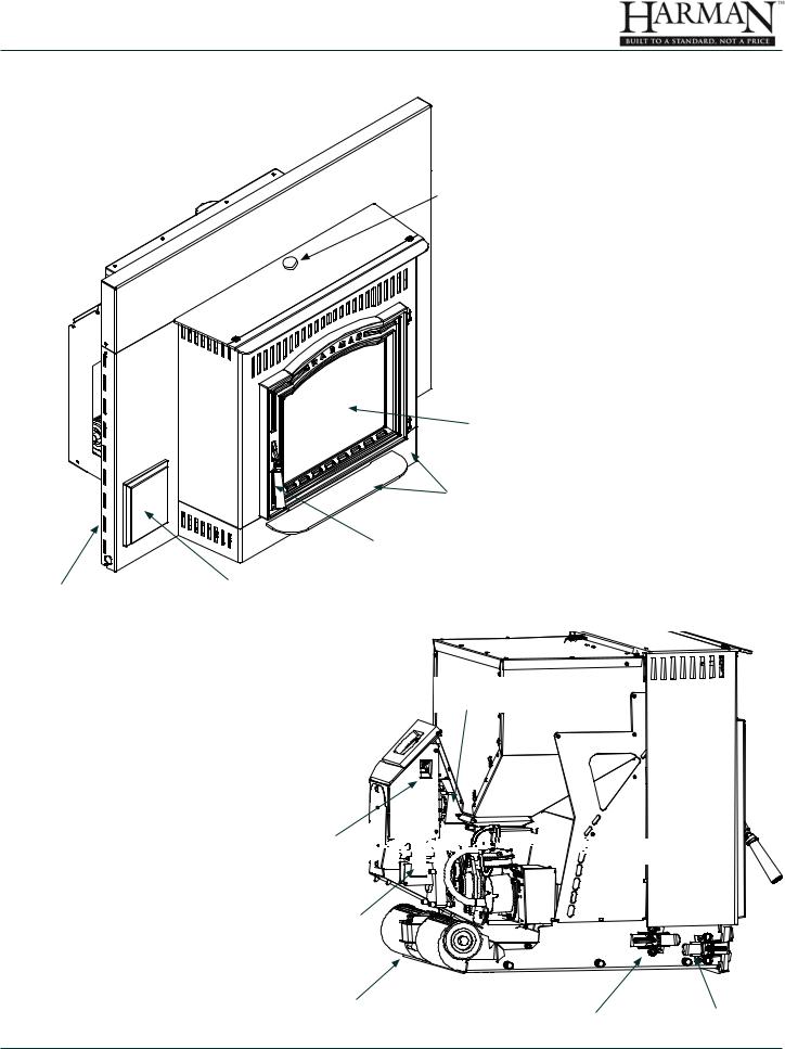
C. Component Locations
 Hopper Lid Latch
Viewing |
Glass |
Ash Pan Cover |
Door Latch
Return Air Slots |
Control Panel |
|
Do Not allow finish materials to block the air flow through the return air slots.
Exhaust
Sensing
Probe (ESP)
Combustion
Blower


 Pellet Pro Feeder
|
Feed Motor |
|
|
|
Distribution Blower |
Frame Latch |
Ash Pan Latch |
|
|
|
|
Save These Instructions |
3-90-775 |
Pellets or Corn/Pellet Mixture Only 7 |
|
P35i Fireplace Insert
D. PreUse Check List
1. |
|
Place the appliance in a location near the |
|
|
final installation and follow the procedures |
|
|
below: |
2. |
|
Open the appliance and remove all articles |
|
|
packed inside. Inspect all items for shipping |
|
|
damage. Notify dealer of any missing or |
|
|
damaged goods. |
3. |
|
All safety warnings have been read and |
|
|
followed precisely. |
4. |
|
This Owner's Manual has been read in it's |
|
|
entirety. |
5. |
|
Floor protection requirements have been |
|
|
read and followed. |
6. |
|
The flue connector has been installed in |
|
|
accordance with the instructions herein. |
7. |
|
The proper clearances from the appliance |
|
|
and chimney connector to combustibles |
|
|
have been met. |
8. |
|
The masonry chimney has been cleaned |
|
|
and inspected by a professional, or the |
|
|
factory built metal chimney is installed |
|
|
according to the manufacturers instructions. |
9. |
|
The chimney meets the minimum height |
|
|
requirements. |
10. |
|
All labels and hang tags have been removed |
|
|
from the glass. |
11. |
|
All plated surfaces have been wiped clean, |
|
|
if applicable. |
12. |
|
The room sensor and any additional cable |
|
|
has been installed properly. |
13. |
|
A properly grounded electrical receptacle is |
|
|
available within reach of the unit's power |
|
|
cord. |
14. |
|
A good quality surge protector is highly |
|
|
recommended to protect the electronics. |
|
|
|
 WARNING
Inspect appliance and components for damage. Damaged parts may impair safe operation.
•Do NOT install damaged components.
•Do NOT install incomplete components.
•Do NOT install substitute components.
Report damaged parts to dealer.
 WARNING
Fire Risk.
Hearth & Home Technologies disclaims any responsibility for, and the warranty will be voided by, the following actions:
•Installation and use of any damaged appliance.
•Modification of the appliance.
•Installation other than as instructed by Hearth & Home Technologies.
•Installation of substitute materials or replacement parts not approved by Hearth & Home Technologies
•Operating appliance without fully assembling all components.
•Do NOT Overfire.
Or any such action that may cause a fire hazard.
8 Pellets or Corn/Pellet Mixture Only |
3-90-775 |
Save These Instructions |
P35i Fireplace Insert
4Dimensions & Clearances
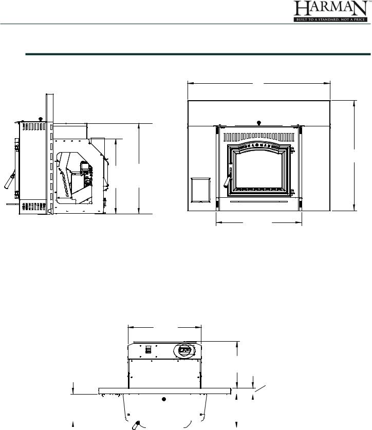
A. Appliance Dimensions
A
19.5” |
49.53 cm Hopper |
23.5” |
59.69 cm Hopper |
B
24” 60.96 cm
|
Standard Surround |
Oversize Surround |
|
# 1-00-774221 |
# 1-00-774250 |
A: |
40" (101.6 cm) |
46" (116.8 cm) |
B: |
31" (78.74 cm) |
34" (86.36 cm) |
22” |
55.88 cm |
14” 35.56 cm
2”  5.08 cm
|
|
|
|
|
|
|
|
|
|
|
|
|
|
|
|
|
|
|
|
|
|
|
|
|
|
|
|
|
|
|
|
|
|
|
|
|
|
|
|
|
|
|
|
|
|
|
|
|
8” |
|
|
|
|
|
|
|
|
|
|
|
|
|
|
|
|||||||
|
|
|
|
|
|
|
|
|
|
|
|
10” |
|||||||||||
20.32 cm |
|
|
|
|
|
|
|
|
|
|
|
||||||||||||
|
|
|
|
|
|
|
|
|
25.4 cm |
||||||||||||||
|
|
|
|
|
|
|
|
|
|
|
|
|
|
|
|
|
|
||||||
|
|
|
|
|
|
|
|
|
|
|
|
|
|
|
|
|
|
|
|
|
|
|
|
|
|
|
|
|
|
|
|
|
|
|
|
|
|
|
|
|
|
|
|
|
|
|
|
|
|
|
|
|
|
|
|
|
|
|
|
|
|
|
|
|
|
|
|
|
|
|
|
Save These Instructions |
3-90-775 |
Pellets or Corn/Pellet Mixture Only |
9 |
|
P35i Fireplace Insert |
|
|
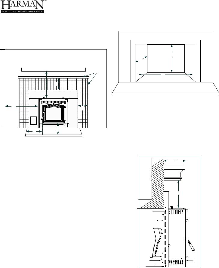
B. Clearances To Combustibles - |
D. Minimum Opening for Masonry |
Masonry or Manufactured Fireplace |
and Manufactured Fireplaces |
The clearances specified are for your safety! These clearances may only be reduced by means approved by the regulatory authority.
|
Mantel |
|
|
Face Trim |
|
Side Wall |
B |
|
D |
||
|
||
A |
C |
|
|
||
F |
E |
|
Location |
Inches |
Millimeters |
|
|
|
|
A |
Insert to combustible sidewall |
13 |
330 |
|
|
|
|
B |
Surround top to face trim |
0 |
0 |
C |
Surround side to face trim |
1 |
25.4 |
|
|
|
|
D |
Insert top to (max) 12" mantel |
12 |
305 |
C. Floor Protection Requirements
|
Location |
Inches |
Millimeters |
|
|
|
|
E |
Window opening to front |
6 |
152 |
|
|
|
|
F |
Window opening to side |
6 |
152 |
Hearth extension must be of a non-combustible material. It must extend beyond the appliance according to the measurements listed.
Minimum Size Hearth Extension is 16" Deep By 32" Wide.
I |
H |
G |
|
Location |
Inches |
Millimeters |
|
|
|
|
G |
Minimum Width |
24 |
609 |
|
|
|
|
H |
Minimum Depth |
14.5 |
368 |
I |
Minimum Height #1-70-774235 |
23½ |
597 |
I |
Minimum Height #1-70-774195 |
19½ |
495 |
E. Mantel Projections
J |
K |
The Maximum mantel depth (J) is 12 inches (305 mm) with a minimum vertical height (K) of 12 inches (305 mm).
10 Pellets or Corn/Pellet Mixture Only |
3-90-775 |
Save These Instructions |
P35i Fireplace Insert
F. Factory-Built Fireplace Installation
When installing the P35i Insert into a factory built wood burning fireplace, several things need to be taken into consideration.
The size of the fireplace opening. Will the unit fit into the opening? Some of the factory built fireplaces have metal smoke shields inside the top that can be removed to gain height. Keep in mind that anything removed from the factory built fireplace must be attached to the fireplace with a metal wire. Floor protection guidelines, as listed previously, must also be followed.
The manufactured fireplace may not be altered beyondtheexceptionslistedbelow.Neverremovemasonry bricks or mortar from an existing fireplace.
The following modifications are permissible:
•Removal of the damper or lock in open position
•Removal of smoke shelf or baffle
•Removal of andirons or ember catchers
•Removal of log grate
•Removal of view screen or curtain
•Removal of doors
•External trim pieces, that do not affect the operation of the fireplace, may be removed providing they can be stored on or within the fireplace for reassembly if the insert is removed.
•If the hearth extension is lower than the fireplace opening, the portion of the insert extending onto the hearth must be supported.
•Final approval of this type of installation is contingent upon the authority having jurisdiction.
Hearth must be constructed to the proper height and finished with a non-combustible material.
The factory built chimney must be listed per UL 127 (US) and meet type HT requirements of UL 103 (US). Factory Built fireplace chimneys tested to UL 127-98 may be, at the fireplace manufacturers option, tested to the same criteria as UL 103HT requirements. If the chimney is not listed as meeting HT requirements, or if the factory built fireplace was tested prior to 1998, a full height listed chimney liner must be installed from the appliance flue collar to the chimney top. Liner must meet high temperature (2100 F) per UL1777 (US). The liner must be securely attached to both the flue collar and the chimney cap. To prevent room air passage to the chimney cavity of the fireplace, seal the damper area around the chimney liner with fiberglass batting.
IN CANADA: This fireplace insert must be installed with a continuous chimney liner of a minimum 3" diameter extending from the insert to the top of the chimney. The chimney  liner must conform to the Class 3 requirements of CAN/ULC-S635, Standard for Lining Systems for Existing Masonry or Factory Built Chimneys and Vents, or CAN/ULCS640, Standard for Lining Systems for New Masonry Chimneys.
When using single-wall |
venting or flex,this section |
of venting must be wrapped |
with a non-combustible |
insulation to prevent excess |
temperatures within the |
fireplace and on the fuel |
hopper. |
Note: If the Harman P35i Insert is installed into a factory built wood burning fireplace, this label (Harman part # 3-90-00675) must be attached to the altered fireplace.
Save These Instructions |
3-90-775 |
Pellets or Corn/Pellet Mixture Only |
11 |
P35i Fireplace Insert
5 |
|
|
|
|
|
|
|
|
|
|
|
|
|
|
|
|
|
|
|
|
|
|
|
|
|
|
|
|
|
|
|
|
|
|
|
|
|
|
|
|
|
|
|
|
|
Chimney connector shall not pass through an attic or roof |
|||||||||||||||||||||||||||||||||||||||||||||||||||||||||||||||||||||
Vent Information |
|
|
|
|
|
|
|
|
|
|
space, closet or similar concealed space, or a floor or ceiling. |
||||||||||||||||||||||||||||||||||||||||||||||||||||||||||||||||||||||||||||||||||||||||||||||||||||||||
|
|
|
|
|
|
|
|
|
|
|
|
|
|
|
|
|
|
|
|
|
|
|
|
|
|
|
|
|
|
|
|
|
|
|
|
|
|
|
|
|
|
|
|
|
|
|
|
|
|
|
|
|
|
|
|
|
|
|
|
|
|
|
|
|
|
|
|
|
|
|
|
|
|
|
|
|
|
||||||||||||||||||||||||||||||||||||||
A. Vent Termination Requirements |
|||||||||||||||||||||||||||||||||||||||||||||||||||||||||||||||||||||||||||||||||||||||||||||||||||||||||||||||||||
|
|
|
|
|
|
|
|
|
|
|
|
|
|
|
|
|
|
|
|
|
|
|
|
|
|
|
|
|
|
|
|
|
|
|
|
|
|
|
|
|
|
|
|
|
|
|
|
|
|
|
|
|
|
|
|
|
|
|
|
|
|
|
|
|
|
|
|
|
|
|
|
|
|
|
|
|
|
|
|
|
|
|
|
|
|
|
|
|
|
|
|
|
|
|
|
|
|
|
|
|
|
|
|
|
|
|
|
|
|
|
|
|
|
|
|
|
|
|
|
|
|
|
|
|
|
|
|
|
|
|
|
|
|
|
|
|
|
|
|
|
|
|
|
|
|
|
|
|
|
|
|
|
|
|
|
|
|
|
|
|
|
|
|
|
|
|
|
|
|
|
|
|
|
|
|
|
|
|
|
|
|
|
|
|
|
|
|
|
|
|
|
|
|
|
|
|
|
|
|
|
|
|
|
|
|
|
|
|
|
|
|
|
|
|
|
|
|
|
|
|
|
|
|
|
|
|
|
|
|
|
|
|
|
|
|
|
|
|
|
|
|
|
|
|
|
|
|
|
|
|
|
|
|
|
|
|
|
|
|
|
|
|
|
|
|
|
|
|
|
|
|
|
|
|
|
|
|
|
|
|
|
|
|
|
|
|
|
|
|
|
|
|
|
|
|
|
|
|
|
|
|
|
|
|
|
|
|
|
|
|
|
|
|
|
|
|
|
|
|
|
|
|
|
|
|
|
|
|
|
|
|
|
|
|
|
|
|
|
|
|
|
|
|
|
|
|
|
|
|
|
|
|
|
|
|
|
|
|
|
|
|
|
|
|
|
|
|
|
|
|
|
|
|
|
|
|
|
|
|
|
|
|
|
|
|
|
|
|
|
|
|
|
|
|
|
|
|
|
|
|
|
|
|
|
|
|
|
|
|
|
|
|
|
|
|
|
|
|
|
|
|
|
|
|
|
|
|
|
|
|
|
|
|
|
|
|
|
|
|
|
|
|
|
|
|
|
|
|
|
|
|
|
|
|
|
|
|
|
|
|
|
|
|
|
|
|
|
|
|
|
|
|
|
|
|
|
|
|
|
|
|
|
|
|
|
|
|
|
|
|
|
|
|
|
|
|
|
|
|
|
|
|
|
|
|
|
|
|
|
|
|
|
|
|
|
|
|
|
|
|
|
|
|
|
|
|
|
|
|
|
|
|
|
|
|
|
|
|
|
|
|
|
|
|
|
|
|
|
|
|
|
|
|
|
|
|
|
|
|
|
|
|
|
|
|
|
|
|
|
|
|
|
|
|
|
|
|
|
|
|
|
|
|
|
|
|
|
|
|
|
|
|
|
|
|
|
|
|
|
|
|
|
|
|
|
|
|
|
|
|
|
|
|
|
|
|
|
|
|
|
|
|
|
|
|
|
|
|
|
|
|
|
|
|
|
|
|
|
|
|
|
|
|
|
|
|
|
|
|
|
|
|
|
|
|
|
|
|
|
|
|
|
|
|
|
|
|
|
|
|
|
|
|
|
|
|
|
|
|
|
|
|
|
|
|
|
|
|
|
|
|
|
|
|
|
|
|
|
|
|
|
|
|
|
|
|
|
|
|
|
|
|
|
|
|
|
|
|
|
|
|
|
|
|
|
|
|
|
|
|
|
|
|
|
|
|
|
|
|
|
|
|
|
|
|
|
|
|
|
|
|
|
|
|
|
|
|
|
|
|
|
|
|
|
|
|
|
|
|
|
|
|
|
|
|
|
|
|
|
|
|
|
|
|
|
|
|
|
|
|
|
|
|
|
|
|
|
|
|
|
|
|
|
|
|
|
|
|
|
|
|
|
|
|
|
|
|
|
|
|
|
|
|
|
|
|
|
|
|
|
|
|
|
|
|
|
|
|
|
|
|
|
|
|
|
|
|
|
|
|
|
|
|
|
|
|
|
|
|
|
|
|
|
|
|
|
|
|
|
|
|
|
|
|
|
|
|
|
|
|
|
|
|
|
|
|
|
|
|
|
|
|
|
|
|
|
|
|
|
|
|
|
|
|
|
|
|
|
|
|
|
|
|
|
|
|
|
|
|
|
|
|
|
|
|
|
|
|
|
|
|
|
|
|
|
|
|
|
|
|
|
|
|
|
|
|
|
|
|
|
|
|
|
|
|
|
|
|
|
|
|
|
|
|
|
|
|
|
|
|
|
|
|
|
|
|
|
|
|
|
|
|
|
|
|
|
|
|
|
|
|
|
|
|
|
|
|
|
|
|
|
|
|
|
|
|
|
|
|
|
|
|
|
|
|
|
|
|
|
|
|
|
|
|
|
|
|
|
|
|
|
|
|
|
|
|
|
|
|
|
|
|
|
|
|
|
|
|
|
|
|
|
|
|
|
|
|
|
|
|
|
|
|
|
|
|
|
|
|
|
|
|
|
|
|
|
|
|
|
|
|
|
|
|
|
|
|
|
|
|
|
|
|
|
|
|
|
|
|
|
|
|
|
|
|
|
|
|
|
|
|
|
|
|
|
|
|
|
|
|
|
|
|
|
|
|
|
|
|
|
|
|
|
|
|
|
|
|
|
|
|
|
|
|
|
|
|
|
|
|
|
|
|
|
|
|
|
|
|
|
|
|
|
|
|
|
|
|
|
|
|
|
|
|
|
|
|
|
|
|
|
|
|
|
|
|
|
|
|
|
|
|
|
|
|
|
|
|
|
|
|
|
|
|
|
|
|
|
|
|
|
|
|
|
|
|
|
|
|
|
|
|
|
|
|
|
|
|
|
|
|
|
|
|
|
|
|
|
|
|
|
|
|
|
|
|
|
|
|
|
|
|
|
|
|
|
|
|
|
|
|
|
|
|
|
|
|
|
|
|
|
|
|
|
|
|
|
|
|
|
|
|
|
|
|
|
|
|
|
|
|
|
|
|
|
|
|
|
|
|
|
|
|
|
|
|
|
|
|
|
|
|
|
|
|
|
|
|
|
|
|
|
|
|
|
|
|
|
|
|
|
|
|
|
|
|
|
|
|
|
|
|
|
|
|
|
|
|
|
|
|
|
|
|
|
|
|
|
|
|
|
|
|
|
|
|
|
|
|
|
|
|
|
|
|
|
|
|
|
|
|
|
|
|
|
|
|
|
|
|
|
|
|
|
|
|
|
|
|
|
|
|
|
|
|
|
|
|
|
|
|
|
|
|
|
|
|
|
|
|
|
|
|
|
|
|
|
|
|
|
|
|
|
|
|
|
|
|
|
|
|
|
|
|
|
|
|
|
|
|
|
|
|
|
|
|
|
|
|
|
|
|
|
|
|
|
|
|
|
|
|
|
|
|
|
|
|
|
|
|
|
|
|
|
|
|
|
|
|
|
|
|
|
|
|
|
|
|
|
|
|
|
|
|
|
|
|
|
|
|
|
|
|
|
|
|
|
|
|
|
|
|
|
|
|
|
|
|
|
|
|
|
|
|
|
|
|
|
|
|
|
|
|
|
|
|
|
|
|
|
|
|
|
|
|
|
|
|
|
|
|
|
|
|
|
|
|
|
|
|
|
|
|
|
|
|
|
|
|
|
|
|
|
|
|
|
|
|
|
|
|
|
|
|
|
|
|
|
|
|
|
|
|
|
|
|
|
|
|
|
|
|
|
|
|
|
|
|
|
|
|
|
|
|
|
|
|
|
|
|
|
|
|
|
|
|
|
|
|
|
|
|
|
|
|
|
|
|
|
|
|
|
|
|
|
|
|
|
|
|
|
|
|
|
|
|
|
|
|
|
|
|
|
|
|
|
|
|
|
|
|
|
|
|
|
|
|
|
|
|
|
|
|
|
|
|
|
|
|
|
|
|
|
|
|
|
|
|
|
|
|
|
|
|
|
|
|
|
|
|
|
|
|
|
|
|
|
|
|
|
|
|
|
|
|
|
|
|
|
|
|
|
|
|
|
|
|
|
|
|
|
|
|
|
|
|
|
|
|
|
|
|
|
|
|
|
|
|
|
|
|
|
|
|
|
|
|
|
|
|
|
|
|
|
|
|
|
|
|
|
|
|
|
|
|
|
|
|
|
|
|
|
|
|
|
|
|
|
|
|
|
|
|
|
|
|
|
|
|
|
|
|
|
|
|
|
|
|
|
|
|
|
|
|
|
|
|
|
|
|
|
|
|
|
|
|
|
|
|
|
|
|
|
|
|
|
|
|
|
|
|
|
|
|
|
|
|
|
|
|
|
|
|
|
|
|
|
|
|
|
|
|
|
|
|
|
|
|
|
|
|
|
|
|
|
|
|
|
|
|
|
|
|
|
|
|
|
|
|
|
|
|
|
|
|
|
|
|
|
|
|
|
|
|
|
|
|
|
|
|
|
|
|
|
|
|
|
|
|
|
|
|
|
|
|
|
|
|
|
|
|
|
|
|
|
|
|
|
|
|
|
|
|
|
|
|
|
|
|
|
|
|
|
|
|
|
|
|
|
|
|
|
|
|
|
|
|
|
|
|
|
|
|
|
|
|
|
|
|
|
|
|
|
|
|
|
|
|
|
|
|
|
|
|
|
|
|
|
|
|
|
|
|
|
|
|
|
|
|
|
|
|
|
|
|
|
|
|
|
|
|
|
|
|
|
|
|
|
|
|
|
|
|
|
|
|
|
|
|
|
|
|
|
|
|
|
|
|
|
|
|
|
|
|
|
|
|
|
|
|
|
|
|
|
|
|
|
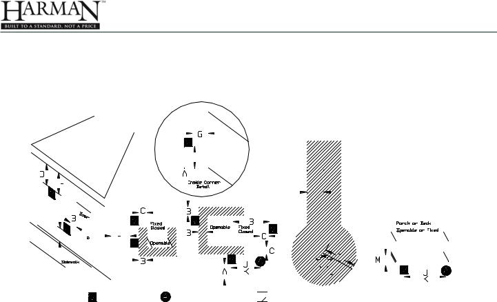
= Vent Termination |
= Air Supply Inlet |
WARNING: Venting terminals must not be recessed into a wall or siding.
NOTE: Only PL or L vent pipe wall pass-throughs and fire stops should be used when venting through combustible materials.
NOTE:Always take into consideration the affect the prevailing wind direction or other wind currents will cause with flyash and /or smoke when placing the termination.
In addition, the following must be observed:
A.The clearance above grade must be a minimum of
18".1
B.The clearance to a window or door that may be opened must be a minimum of 48" to the side and 48" below the window/door, and 12" above the window/door.1
(with outside air installed, 18” to side and below)
C.A 12" clearance to a permanently closed window is recommended to prevent condensation on the window.
D.The vertical clearance to a ventilated soffit located above the terminal within a horizontal distance of 2 feet (60 cm) from the center-line of the terminal must be a minimum of 18".
E.The clearance to an unventilated soffit must be a minimum of 12".
F.The clearance to an outside corner is 11" from center of pipe.
G.The clearance to an inside corner is 12".
H.A vent must not be installed within 3 feet (90 cm) above a gas meter/regulator assembly when measured from the horizontal center-line of the regulator.1


 = Restricted Area
I.The clearance to service regulator vent outlet must be a minimum of 6 feet.1
J.The clearance to a non-mechanical air supply inlet to the building or the combustion air inlet to any other appliance must be a minimum of 48”.1
K.The clearance to a mechanical air supply inlet must be a minimum of 10 feet.1
(with outside air installed, 6 feet )
L.The clearance above a paved sidewalk or a paved driveway located on public property must be a minimum of 7 feet.1,2
M.The clearance under a veranda, porch, deck or balcony must be a minimum of 12 inches.1,3 (B. also)
NOTE: The clearance to vegetation and other exterior combustibles such as mulch is 36” as measured from the center of the outlet or cap. This 36” radius continues to grade or a minimum of 7 feet below the outlet.
1Certain Canadian and or Local codes or regulations may require different clearances.
2Avent shall not terminate directly above a side-walk or paved driveway which is located between two single family dwellings and serves both dwellings.
3Only permitted if veranda, porch, deck, or balcony is fully open on a minimum of 2 sides beneath the floor.
NOTE: In Canada, where passage through a wall or partitionofcombustibleconstructionisdesired,the installation shall conform to CAN/CSA-B365.
12 Pellets or Corn/Pellet Mixture Only |
3-90-775 |
Save These Instructions |

P35i Fireplace Insert
B. Avoiding Smoke and Odors
Negative Pressure, Shut-down, and Power
Failure:
To reduce the probability of back-drafting or burnback in the pellet burning appliance during power failure or shut-down conditions, the stove must be able to draft naturally without exhaust blower operation. Negative pressure in the house will resist this natural draft if not accounted for in the pellet appliance installation.
Heat rises in the house and leaks out at upper levels. This air must be replaced with cold air from outdoors, which flows into lower levels of the house. Vents and chimneys into basements and lower levels of the house can become the conduit for air supply, and reverse under these conditions.
Outside Air:
Harman Home Heating and Hearth & Home Technologies recommend attaching outside air in all installations, especially lower level and main floor locations.
Per national building codes, consideration must be given to combustion air supply to all combustion appliances. Failure to supply adequate combustion air for all appliance demands, may lead to back-drafting of those and other appliances.
When the appliance is side-wall vented: The air intake is best located on the same exterior wall as the exhaust ventoutletand locatedloweronthewallthan the exhaust vent outlet.
When the appliance is roof vented: The air intake is best located on the exterior wall oriented towards the prevailing wind direction during the heating season.
The outside air connection will supply the demands of the pellet appliance, but consideration must be given to the total house demand. House demand may consume some air needed for the stove, especially during a power failure. It may be necessary to add additional ventilation to the space in which the pellet appliance is located. Consult with your local HVAC professional to determine the ventilation demands for your house.
The outside air kit consists of a flue stub pipe, fiberglass gasket, silicone gasket, intake box and a section of flex pipe.
An adjustable chimney intake extension, part # 1-00- 674104 is available to be used on masonry chimneys only.
To install outsideair,use kit part number1-00-774280. Follow the installation instructions provided with the kit.
Vent Configurations:
To reduce probability of reverse drafting during shut-down conditions, Hearth & Home Technologies strongly recommends:
•Installing the pellet vent with a minimum vertical run of five feet, preferably terminating above the roof line.
•Installing the outside air intake at least four feet below the vent termination.
To prevent soot damage to exterior walls of the house and to prevent re-entry of soot or ash into the house:
•Maintain specified clearances to windows, doors, and air inlets, including air conditioners.
•Vents should not be placed below ventilated soffits. Run the vent above the roof.
•Avoid venting into alcove locations.
•Vents should not terminate under overhangs, decks or onto covered porches.
•Maintain minimum clearance of 12 inches from the vent termination to the exterior wall. If you see deposits developing on the wall, you may need to extend this distance to accommodate your installation conditions.
Hearth & Home Technologies assumes no responsibility for, nor does the warranty extend to, smoke damage caused by reverse drafting of pellet appliances under shut-down or power failure conditions.
Do not connect this unit to a chimney flue servicing another appliance.
NOTE:The restriction of not venting more than one appliance to the same flue applies to the U.S. specifically. While it is not recommended that you use the same chimney for more than one appliance, in Canada certain exceptions may be made. Be sure to contact your building code inspection official to see if this option is allowed in your area, and to find out the specific requirements for such an installation.
Do not connect this unit to any air distribution duct or system.
Save These Instructions |
3-90-775 |
Pellets or Corn/Pellet Mixture Only |
13 |

P35i Fireplace Insert
C. Venting Requirements and Restrictions
A combustion blower is used to extract the combustion gases from the firebox.This causes a negative pressure in the firebox and a positive pressure in the venting system. The longer the vent pipe and more elbows used in the system, the greater the flow resistance.
The recommended maximum flue lengths for the P35i Insert are as follows:
3" or 4" Stainless Steel Flex: 30 Lineal ft. Vertical*
4" PL Vent Pipe:
4" Pl Vent Pipe: 30 Lineal ft. Vertical*
4" Pl Vent Pipe: 14 ft. Vertical w/1-90o and 12 lineal ft. horizontal*
If additional 4" PL Vent fittings are required, the overall length must be reduced by:
Vertical 90o or T: |
2.5' |
|
Vertical 45o: |
1.5' |
|
Horizontal |
90o or T: |
5.0' |
Horizontal |
45o: |
2.5' |
3" PL Vent Pipe:
20 Lineal ft. vertical*
8 Lineal ft. vertical w/1-90o & 8 lineal ft. horizontal*
If additional 3" PL Vent fittings are required, the overall length must be reduced by:
Vertical 90o or T: |
2.0' |
|
Vertical 45o: |
1.0' |
|
Horizontal |
90o or T: |
4.0' |
Horizontal |
45o: |
2.0' |
* Long runs of flex or PL vent pipe installed directly vertical from the flue stub may require more frequent cleaning due to fly ash falling off inside and collecting directly above the combustion blower outlet.
Any use of horizontal venting will require more frequent cleaning. It is the responsibility of the installer to make sure the entire flue configuration is accessible for cleaning.
Stainless steel flex vent is only allowed for use in masonry fireplaces and chimneys or in factory built wood burning fireplace installations when used as a liner for a class A metal chimney. All pellet vent pipe must be secured together by means provided by pipe manufacturer. The vent pipe must be secured to the appliance flue collar with a minimum of three screws.
It is also recommended that you seal all vent pipe joints with high temperature silicone.
Use only the specified venting components. Use of any other components will void the product warranty and may pose a hazard.
Do Not Install A Flue Damper In The Exhaust Venting System Of This Appliance.
DO NOT CONNECT THIS UNIT TOACHIMNEYFLUE SERVING ANOTHER APPLIANCE.
NOTE: If burning a shelled corn and pellet mixture, you must use approved venting components that are specifically designed for corn burning.
WARNING! RISK OF FIRE!
•Only LISTED type L or PL Pellet venting components may be used.
•NO OTHER type of venting materials or components may be used.
•Substitute or damaged vent components may impair safe operation.
WARNING! RISK OF INJURY OR PROPERTY DAMAGE!
•Improper installation, adjustment, alteration, service, or maintenance can cause injury or property damage.
•Read and Refer to your owner's manual.
•For assistance or additional information, consult a qualified installer, service agency or your dealer.
IN CANADA: This fireplace insert must be installed with a continuous chimney liner of a minimum 3" diameter extending from the insert to the top of the chimney. The chimney liner must conform to the Class 3 requirements of CAN/ULCS635, Standard for Lining Systems for Existing Masonry or Factory Built Chimneys and Vents, or CAN/ULC-S640, Standard for Lining Systems for New Masonry Chimneys.
14 Pellets or Corn/Pellet Mixture Only |
3-90-775 |
Save These Instructions |
P35i Fireplace Insert
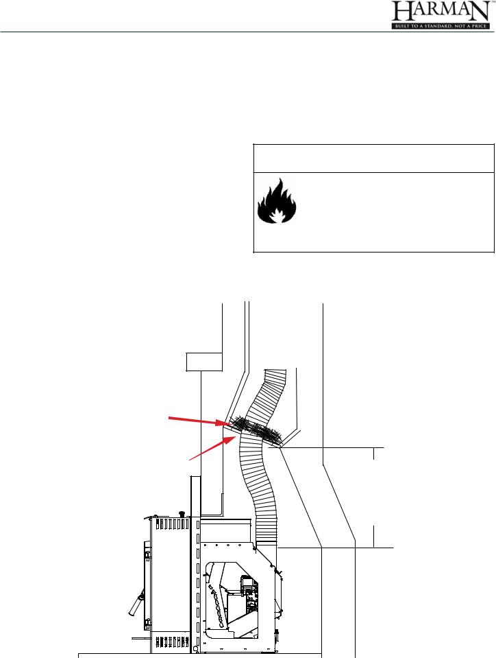
D. Existing Fireplace Installation:
If using a short run of venting, whether flex or rigid, through the damper and into the chimney flue; The Damper must be removed or locked in the open position and sealed with a plate constructed of steel or other non-combustible material.
Kaowool, mineral wool or other non-combustible insulation is recommended above the plate to reduce the possibility of condensation. You will also need to wrap the venting section between the insert frame and the damper sealing plate. This is to prevent overheating of the fireplace cavity, which may cause damage to the insert's motors and other electrical components. The connector pipe should extend through the sealing plate and smoke chamber and into, or beyond the first flue tile.
Be sure to design the venting so that it can be easily cleaned.
Check with your local authority having jurisdiction to determine if this venting method is acceptable. Some Provincial, State, or Local codes may require a full liner run to the top of the chimney. Be sure and check your local regulations before planning the installation. In this method, the proper flashing and rain cap are also required.
 WARNING
Fire Risk.
Inspect Chimney
•Masonry chimney must be in good condition
•Meets minimum of NFPA 211 standard
•Factory-built chimney must meet requirements of UL103 HT
IN CANADA: This fireplace insert must be installed with a continuous chimney liner of a minimum 3" diameter extending from the insert to the top of the chimney. The chimney liner must conform to the Class 3 requirements of CAN/ULC-S635, Standard for Lining Systems for Existing Masonry or Factory Built Chimneys and Vents, or CAN/ULCS640, Standard for Lining Systems for New Masonry Chimneys.
Non-combustible
Insulation
When venting in this configuration, a rain cap and proper flashing must be installed on the top of the chimney to prevent flooding and damage.
Tile Flue Liner

Sealing Plate
When using single wall flex, this section of venting must be wrapped with non-combustible insulation to prevent excessive heat build-up in the cavity.
Save These Instructions |
3-90-775 |
Pellets or Corn/Pellet Mixture Only |
15 |
 Loading...