

Page 1
Installation and Operator’s Manual
SF-150
SF-250
KEEP THESE INSTRUCTIONS
“Built to a Standard, Not a Price.”
2003
CAUTION: Read Warnings and Safety Considerations/
Recommendations for safe installation & operation.
Page 2

Thank you . . .
THANK YOU FOR PURCHASING A HARMAN STOVE AND FOR READING
THIS OWNER’S MANUAL. It is our desire to provide as much data as needed to allow
you to install and operate your Harman Stove in the safest manner possible.
There are a number of excellent sources on wood heating which you might like to
purchase for your home library. These include “The Woodburning Encyclopedia” by Jay
W. Shelton; “Wood Heat” by John Vivian; and “The Complete Book of Heating With
Wood” by Larry Gay. Local fire departments provide an excellent source of counsel for the
novice woodburning customer.
If you have any questions regarding your Harman Stove which were not covered in
this manual, contact your local dealer or factory direct.
Page 3

Index
INTRODUCTION
READ ALL INFORMATION “PRIOR” TO PROCEEDING WITH INSTALLATIONS, AND CHECK
WITH YOUR LOCAL AUTHORITIES FOR PREVAILING FIRE ORDINANCES AND RECOMMENDATIONS.
1. SAFETY CONSIDERATIONS - Warnings to owner/operator of possible dangers, fire hazards and
cautions.
1.1 Keep children away -- may cause serious burns.
1.2 Fuel/Firing Warnings
1.3 Curing Paint
1.4 Mobile Homes
2. ACCESSORIES
2.1 Heat Collector or Plenum
3. ASSEMBLY
4. CHIMNEY - Proper draft/venting
4.1 Types of Chimneys
4.2 Common Chimney Problems
4.3 What To Do When You Have A Problem
4.4 Chimney Details
5. CREOSOTE AND SOOT
5.1 General And Specific Creosote Maintenance “Warnings”
6. ELECTRICAL
6.1 Electrical Warnings
7. FUEL
7.1 Firewood and Coal Fuel Information Sheet
8. GRATES
8.1 Grate System and Controls
9. INSTALLATION INSTRUCTIONS
9.1 Unpacking and Inspection of Parts
9.2 Warnings
9.3 Locating the Stove
9.4 General Information
10. PREVENTIVE MAINTENANCE INSTRUCTIONS
10.1 Periodic and Normal Everyday
11. OPERATING INSTRUCTIONS
11.1 Starting a Wood Fire
11.2 Starting A Coal Fire
11.3 Loading
11.4 Increase Heat From A Low Fire
11.5 Shaking
11.6 Draft controls
11.7 Secondary Air
11.8 Ashes
11.9 Safety
12. WARRANTY
12.1 Terms - Warranty
13. OPTIONAL HOT WATER COIL
Page 4

1.1 KEEP CHILDREN AWAY -MAY CAUSE SERIOUS BURNS
CAUTION: ALL SURFACES OF
STOVE ARE HOT. DO NOT
TOUCH! KEEP CHILDREN AWAY.
SERIOUS BURNS WILL RESULT
IF TOUCHED. THIS IS A HEAT
PRODUCING APPLIANCE. SERIOUS BURNS MAY RESULT IF
THE STOVE IS TOUCHED DURING FIRING.
1.2 FUEL/FIRING WARNINGS
DANGER! FIRE HAZARD! DO
NOT USE CHEMICALS OR FLUIDS TO START OR “FRESHEN
UP” A FIRE. SEVERE BODY
BURNS OR A FIRE IN YOUR
HOME COULD RESULT. DO NOT
BURN GARBAGE, GASOLINE,
THINNERS, DRAIN OR ENGINE
OIL, KEROSENE, OR FUEL OIL,
ETC. AN EXPLOSION, A HOUSE
FIRE OR PERSONAL INJURY
COULD RESULT. KEEP ALL
SUCH LIQUIDS WELL AWAY
FROM THE STOVE WHILE IN
USE.
“NEVER” burn materials other than
coal or split and dried wood logs. A
chimney fire or heat exchanger failure could result. This includes large
amounts of corrugated boxes, wood
shavings, paper scraps, dried
Christmas trees, coke, garbage,
tires, or other burnable products.
When and if the chimney pipes or
connectors reach 500 degre e s
fahrenheit (maximum temperature),
the stove is being over-fired. We recommend the purchase of a Harman
Magnetic Te m p e r a t u re Gauge to
monitor the stove and stack temperatures relative to the amount of draft
the customer permits the stove to
operate.
It has been verified that creosote will
ignite at 650 degrees fahrenheit. It
is the owner’s responsibility to follow these recommendations.
This stove consumes air when it is
burning. It is advisable that a window in the vicinity be opened slightly while stove is burning if your
house is tightly sealed and insulated.
(Information contained in this manual is manufacturer’s recommendations and if there is any difference
between our recommendations and
local code requirements, we suggest
following local code requirements.)
1.3 Curing Paint
During the first few hours of burning, a blue smoke will be observed
rising from the painted surface of
the stove. It is advisable to increase
the amount of fresh air in the room
during this breaking-in period. This
may be achieved by opening doors,
windows, etc. Don’t be alarmed,
this is normal.
1.4 Mobile Home
Harman Stoves are not approved or
recommended for mobile homes.
2.1 Heat Collector
Optional Heat Collector can be
attached to the top of the stove to
direct heat from the spiral chamber
and stove top into a duct. CAUTION: The duct rising off the heat
collector should be kept ten inches
away from combustible materials for
the first fifteen feet from the stove.
This includes floor joists, suspended
ceilings, etc. Clearances may be
reduced if fireproof material such as
asbestos board or sheet metal with
air space is used to protect combustibles. The heat collector slides
on easily from the front of the unit.
(See diagram on following page.)
1. Safety Considerations
2. Accessories
Page 5
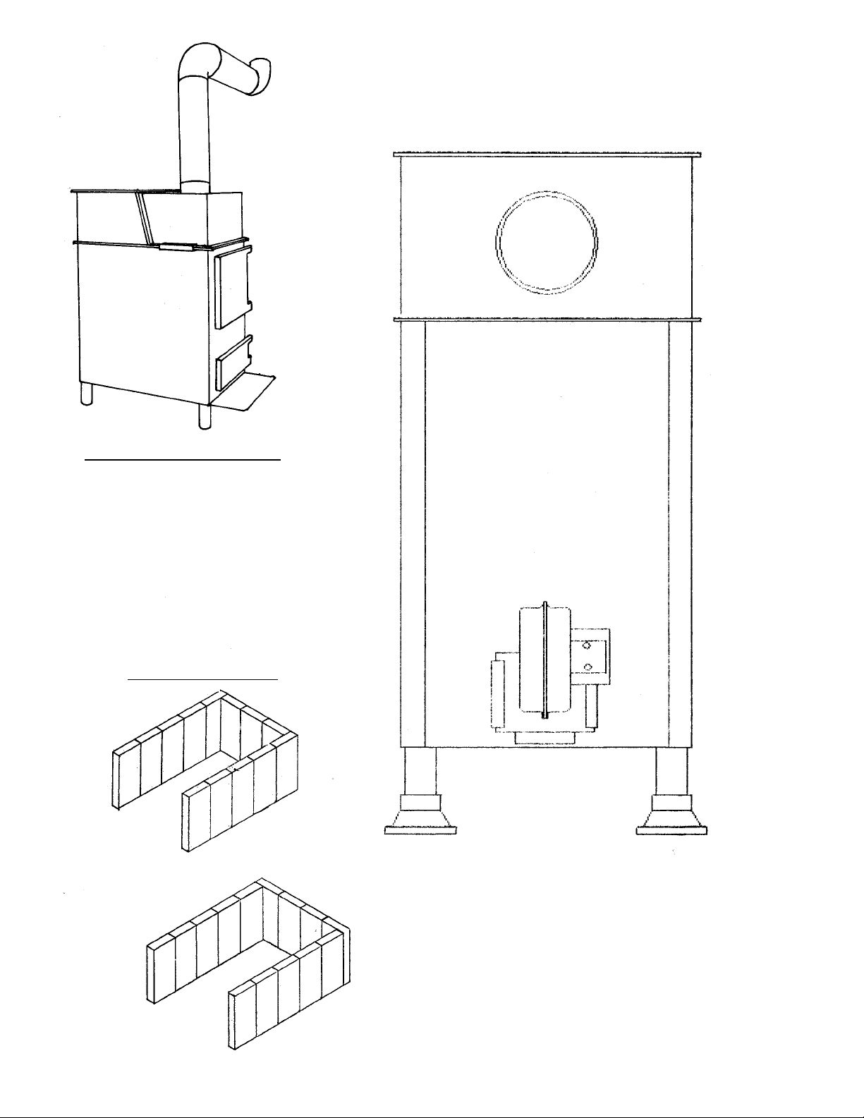
3. Assembly
Fasten blower to rear of stove
by sliding blower into slots
provided.
Heat Collector Diagram
Firebrick Diagram
SF-150
SF-250
Page 6
4. Chimney
4.1 Types of Chimneys
The chimney is one of the most
important, yet most neglected and
misunderstood portion of any solid
fuel burning installation. We do not
recommend that the stove be connected to a chimney with other
heating devices.
THE STOVE MUST BE CONNECTED TO ITS OWN TILELINED FLUE. A MINIMUM FLUE
SIZE OF 8" X 8" IS NECESSARY
FOR PROPER OPERATION AND
APPROVED FOR ALL FUELS.
UNDER NO CIRCUMSTA N C E S
SHOULD A MANUAL FLUE
DAMPER BE INSTALLED IN THE
SMOKE PIPE BETWEEN STOVE
AND CHIMNEY!
No damper, heat saver, or automatic vent damper device should be
installed in or on the smoke pipe.
N O O T H E R A P P L I A N C E S
SHOULD BE VENTED TO THIS
FLUE!
CAUTION: THE CHIMNEY MUST
BE A CLASS “A” CHIMNEY IN
GOOD OPERATION CONDITION.
NOTE: THE USE OF ALUMINUM
TYPE “B” GAS VENT FOR SOLID
FUELS IS UNSAFE AND PROHIBITED BY THE NATIONAL FIRE
PROTECTION ASSOCIAT I O N
CODE.
There are three types of class “A”
chimneys:
A. Masonry with tile liner to
include brick or stone. It must be
supported on grade level foundation.
B. Insulated Class “A” manufactured chimney, listed or certified by
a national test agency.
C. Triple Wall Metal Class “A”
chimney, listed or certified by a
national test agency.
If your masonry chimney has not
been used for some time, have it
inspected by a qualified person
(building inspector, fire department
personnel, etc.). If a listed or certified manufactured chimney is to be
used, make certain it is installed in
accordance with the manufacturer’s
instructions and all local and state
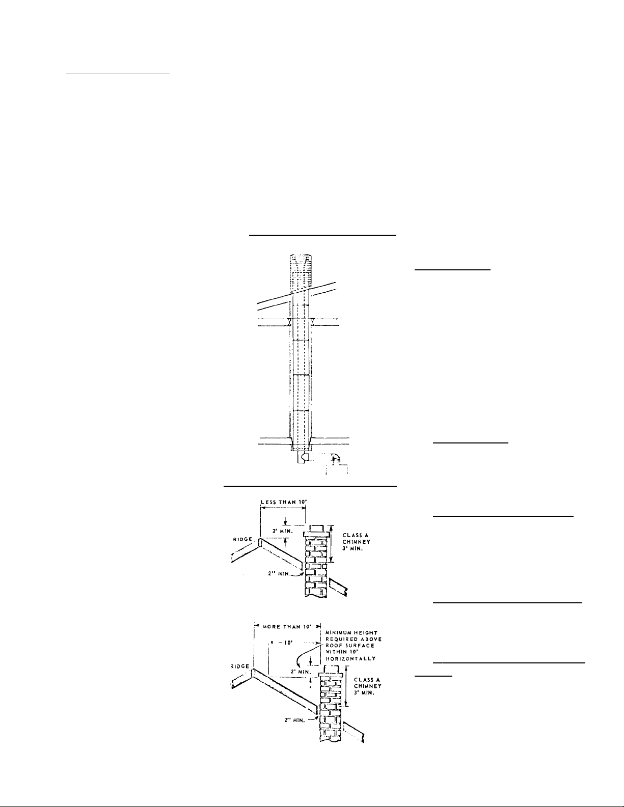
codes. See Figure No. 1 of
Manufactured Chimney Installations
and Figure No. 2 of masonry
Chimney (note roof clearance) in
accordance with NFPA 211.
4.2 Common Chimney Pro b l e m s
In order to have a proper operating
solid fuel heating system, the chimney must be capable of providing
the draft required.
The minimum required draft is .06
inches W.C. (water column). This
must be measured using a draft
gauge.
If the chimney cannot supply this
constant draft, the unit will not
operate properly.
In some installations, a barometric
draft regulator may be used and
properly adjusted to compensate for
excessive draft.
IMPORTANT!
Whenever you measure the draft,
the stove must be operating and sufficient time given for the chimney
and stove to warm up. This should
take a minimum of thirty minutes.
The draft reading is taken 18" up
from the center of the stove flue
outlet in the smoke pipe.
REASONS for insufficient draft
readings:
A. Leaky Chimney - Air leaking in
a r ound a loose fitting clean-out
door, flue pipes not tight at the
joints, improper plug openings or
defective masonry.
B. Chimney Improper Height Chimney does not extend through
the roof to a sufficient height to promote sufficient draft or causes a
down drafting condition to take
place. (See Figure No. 3)
C. Obstructions in the chimney.
Check prior to using by holding a
mirror in chimney clean-out door.
This will give a view of the chimney.
D. Trees or Other Topographical
Barriers - Impeding the chimneys
operation or causing a down draft
condition to exist. This can also be
caused by adjacent buildings or the
roof of the same structure where the
chimney is not high enough. (See
Figure No. 3)
Figure 2
Figure 1
Page 7

NOTE: The Chimney on the house
illustrated is too low. It should be
raised to compensate for drafts.
E. Chimney Size - Chimney is not
properly sized to adequately vent
the appliance. It is either too small
or too large.
F. Chimney Offsets - Chimneys
with offsets should not be used.
They cause an obstruction to draft
as well as a place for debris to collect.
G. Elbow Restrictions - The flue
pipe is connected to the chimney
with too many elbows, reducing the
draft the chimney can provide.
H. Multiple Venting - No more than
one device shall vent into the same
chimney flue.
THE MOST IMPORTANT THING
TO REMEMBER ABOUT CHIMNEYS IS THEIR NEED FOR MAINTENANCE AND CLEANING. IF
CHIMNEYS ARE NOT CLEANED
ON A FREQUENT BASIS, IT WILL
AFFECT THE DRAFT, AS WELL
AS BEING A CONTRIBUTING
CAUSE TO A CHIMNEY FIRE.
CAUTION
ANYTIME YOU HAVE A CHIMNEY FIRE THE FOLLOWING
POINTS SHOULD BE
OBSERVED:
1. BE SURE EVERYONE IS OUT
OF THE HOUSE.
2. CALL THE FIRE DEPA RTMENT.
3. CLOSE DOWN DRAFT
DAMPER ON STOVE.
AFTER THE FIRE IS EXTINGUISHED, DO NOT USE THE
CHIMNEY UNTIL A QUALIFIED
PERSON HAS INSPECTED YOUR
CHIMNEY.
4.3 What To Do When You
Have A Problem
A. Smoke Puffs From Your
Stove:
1. Check the chimney draft. With a
good fire burning, the chimney
should supply .06" updraft.
2. Check draft controls for proper
operation.
3. Check the smoke pipe and be
sure it is clean.
4. Chimney may be too low.
Increase the height. Make sure the
chimney is structurally sound.
5. Add more air to the room. Your
home may be so airtight that not
enough oxygen is reaching the fire.
6. REMEMBER, open the draft
controls and crack the fire door
slightly before recharging the fire
chamber or checking the fire.
SPECIAL WARNING: NEVER
OPERATE YOUR STOVE WITH
THE FIRE OR ASH DOOR OPEN!
7. Check the smoke pipe and
make certain each joint is tight and
the connections to the stove and
chimney are airtight.
8. Check the ashes. Ashpan and
f i re compartment may be overloaded with ashes.
9. Check type of wood being
burned. If too green or wet wood is
being used, it may cause excessive
smoking and creosote.
10. Check your chimney for down
drafts. This is caused by air currents
being deflected down the chimney
from higher objects, such as trees,
building and hills. This problem can
usually be corrected with an openvented chimney cap.
11. Make sure the chimney cleanout door is tightly closed and sealed.
12. If other fuel-burning devices are
connected to the chimney they may
be causing draft problems. This
must be corrected by your heating
contractor.
4.4 Chimney Details
Chimney Liners - Most of the customer inquiries received are problems caused by poor, or in some
cases, excessive draft. A result of
poor draft could be creosote, backpuffing, and smoky firebox when
loading. Indications of excessive
draft are burning too much fuel and
high stack temperatures.
Figure 3
RECOMMENDED SIZING CHIMNEY FLUE LINERS
FURNACE COLLAR CHIMNEY LINER
INSIDE
DIAMETER AREA ROUND SQ. OR DIMENSION AREA EQUIV.
(SQ. IN.) ID RECT. (APPROX.) (SQ. IN.) DIA
6" 28.3 6"-7" 8" x 8" 6 1/2" x 6 1/2" 42.7 7.4"
7" 38.3 7"-8" 8" x 8" 6 1/2" x 6 1/2" 42.7 7.4"
8" 50.3 8"-9" 8" x 12" 6 1/2" x 10 1/2" 63.6 9"
Page 8

The most common cause of poor
draft is an improperly sized flue
liner. We recommend that the chimney liner’s inside dimensions be at
least as large as the appliance’s collar size and no larger than 125% of
the collar for a round flue. For
instance, an 8" furnace collar is 50
square inches; increased by 25"%
would be 63 square inches, or
approximately a 9" round flue. In
general for round liners we recommend that they not be increased
more than 1" from that of the
Harman’s collar size. The reason for
the above is that Harman appliances are designed to produce the
maximum amount of heat per
amount of fuel burned. A a result,
the flue gas temperature is lower
than for some similar equipment.
TO SUMMARIZE, A HEAT I N G
UNIT CAN PERFORM ONLY AS
WELL AS ITS VENTING SYSTEM
WILL ALLOW IT.
5. Creosote
and Soot
5.1 General and Specific
C r eosote Maintenance
Wa r n i n g s
One of the most critical aspects of
operating a woodburning stove is
the control of creosote and soot.
This is especially important when
there is a low demand for heat, such
as in the fall or spring. A good
understanding of the causes and
cures for excess creosote or soot
formation is essential to the operation of the stove.
Your stove and for that matter, all
types and makes of woodburning
equipment will give trouble with creosote deposits under certain conditions. You should be aware of these
conditions and avoid them.
When wood is burned slowly, it produces acetic and other pyroligneous
acids that combine with expelled
moisture to form creosote. Highly
combustible in its solid and semi-liquid states, creosote is present in the
gases given off by burning wood.
Creosote may build to a considerable thickness on the interior surface of the chimney and stove pipe
subsequently reducing draft. A
SERIOUS FIRE MAY BE IGNITED
IF A SUFFICIENT CREOSOTE
BUILDUP IS PERMITTED.
Creosote condenses from the flue
gases more quickly when the temperature of those gases is low. The
actual amount of creosote deposited
depends on (1) the amount of moisture in the flue gases, (2) the temperature of the stack, (3) the rate at
which the wood is burned, (4) the
amount of draft in the stack, and (5)
how completely the combustible elements in the flue gases have been
burned in the combustion chamber.
Most problems with creosote are
due to insufficiently dry wood, poor
chimneys with low draft and cold
walls, and/or a low rate of burning
when little heat is required during
the spring and fall months.
Moisture in the Flue Gases May Be
Controlled by:
A. Using properly seasoned firewood.
B. Mixing small pieces with every
full load.
C. Never using only large (usually
less dry) wood during mild weather
when combustion is relatively slow.
The Temperature in the Stack May
be Controlled by:
A. Using as short a length of
stovepipe as possible between the
stove and the chimney.
B. Using an insulated flue pipe to
connect the stove to the chimney.
The Amount of Draft in the Stack
May be controlled by:
A . Having as few bends as possible.
B. Insuring adequate chimney
height and preventing air leaks.
C. Eliminating external obstructions in the chimney outlet.
D. Having only one appliance per
flue.
C A U T I O N ! O W N E R ’ S
R E S P O N S I B I L I T Y
YOU MUST CHECK YOUR
CHIMNEY FLUE PIPE CONNECTOR FREQUENTLY WHEN FIRST
STARTING TO BURN WOOD TO
DETERMINE THE AMOUNT OF
CHIMNEY MAINTENANCE (CLEANING) THAT WILL BE REQUIRED.
THIS OF COURSE, IS ALSO
DEPENDENT ON WOOD TYPE,
MOISTURE, AND IN GENERAL,
HOW THE STOVE IS USED.
The chimney connector and chimney should be inspected at least
twice monthly during the heating
season to determine if a creosote
Page 9

build-up has occurred.
If creosote has accumulated, it
should be removed to reduce the
risk of a chimney fire.
If an over-fire situation should occur,
be sure ash door and fire door are
closed.
In the event of a soot fire, call your
fire department immediately, and
make sure the ash door, fire door
and drafts are closed.
6. Electrical
6.1 Wa r n i n g s
Turn off electric power at fuse box
or circuit breaker panel before making any line voltage connections.
Follow local electrical codes. Be
sure to route power so that it doesn’t come in contact with the stove.
I M P O R TA N T ! ALL WIRING
SHOULD BE DONE IN ACCORDANCE WITH LOCAL AND
STATE CODES.
7. Fuel
7.1 F i r ewood and Coal Fuel
I n f o r mation Sheet
The energy content of most hardwoods, and all but a few softwoods,
is generally estimated to be around
8,6000 BTU’s per pound at zero
p e r cent moisture content. This,
however, would not be a practical
value to use in the calculation of fuel
needed to meet a given heat load.
All the BTU’s available in wood are
not generated as usable, sensible
heat. Much of this heat is dependent
on the appliance’s efficiency and is
required in the venting system to
generate a draft. Also, firewood is
not available at zero percent moisture. Well seasoned, sheltered wood
contains an approximate minimum
moisture of 20%, where the same
wood left to the elements may have
a moisture content as high as 80%.
One cubic foot of hardwood weighs
about 45 pounds. One cubic foot of
water weighs 62.5 pounds, and the
amount of energy required to evaporate only one pound of this water
is over 1,000 BTU’s. If the same
cubic foot of hardwood has a moisture content of 80%, it would weigh
approximately 80 pounds, and the
energy lost in boiling off this moisture could theoretically be as high as
35,000 BTU’s, not to mention a
sore back from carrying the soggy
stuff.
In summary, burn only well-seasoned dry wood. Wood must not
only be of a reasonable quality and
seasoned, but to get its maximum
heat energy output, it must be dry.
S e a s o n i n g - unseasoned (gre e n )
wood, when used as fuel, offers
many potential problems. It is of
course much heavier than seasoned
wood because of its high moisture
content. When burned, it loses
much of its heat value in boiling off
this moisture. It is difficult to ignite
and is sometimes hard to keep burning. But its major evil is creosote, as
will be discussed in the next section.
Seasoning is easy! The cutting,
stacking, and putting it under cover
is the hard part; but once this is
done, just leave it alone. leave it
alone for at least one year -- better
two. If wood is cut in the dead of
winter, little seasoning takes place
until the temperature rises above
f r eezing. If the wood is store d
unprotected, minimal seasoning can
occur. Moisture from high humidity,
rain, snow, dew, etc., will be
absorbed into the wood and then
must be evaporated before the seasoning process can begin again. If
you live in an area where the winters are long and hard, you can
expect your wood to take longer to
season than wood stored in a more
temperate climate. However, as
wood is susceptible rot, it can be
stored too long. Rotten wood contains less heat energy than good
wood, so the more advanced the
rotting, the less BTU’s can be
derived from the fuel.
Choosing a kind of firewood to burn
in your stove naturally depends on
what is available to you. If all you
can obtain is softwood, obviously,
that will be your choice.
Softwoods like pine, spruce, and fir
are easy to ignite because they are
resinous. They burn rapidly with a
hot flame. However, since a fire
built entirely of softwoods burns out
quickly, it requires frequent attention and replenishment.
This characteristic of softwoods can
be a boon, if you want a quick
warming fire or a short fire that will
burn out before you go to bed.
If you do have a choice, for a long
lasting fire, it is best to use the heavier hardwoods such as ash, beech,
birch, maple and oak.
By mixing softwoods with hardwoods, you can achieve an easily
ignited and long lasting fire.
So that you have an idea of how
firewood is described and sold, you
should first know that the most
common measure is the standard
cord. A cord is a well-stacked pile of
logs 4 ft. by 4 ft. by 8 ft. Wood is
also sold by the ton.
If you buy wood by weight, look for
the driest wood. Don’t pay for extra
water! Small twigs and branches
found in your yard and wood wastes
found around sawmills are also
good. When you buy wood, request
a mixture of wood species and
diameter sizes. the wood should be
generally sound, but don’t worry
about small pockets of rotten wood
that you may find in logs.
Page 10

HOW MUCH AVAILABLE HEAT IS THERE
IN AIR-DRIED (20% MOISTURE) WOOD PER CORD?
APPROX. B.T.U. AVAILABLE
AVERAGE WEIGHT IN AN AIR-DRIED CORD ORDER OF MOST
TYPE PER CORD BURNED AT 50% EFFICIENCY HEAT PER CORD
Ash 2.950 lbs. 11,300,000 Eleventh
Aspen 1,900 lbs. 8,850,000 Fifteenth
Basswood 1,900 lbs. 8,550,500 Sixteenth
Beech 3,240 lbs. 13,900,000 Third
Birch (Yellow) 3,000 lbs. 13,100,000 Sixth
Cherry 2,550 lbs. 11,750,000 Tenth
Elm 2,750 lbs. 12,250,000 Seventh
Hemlock 2,100 lbs. 8,955,000 Thirteenth
Hickory 3,595 lbs. 15,300,000 First
Maple (Hard) 3,075 lbs. 14,500,000 Second
Maple (Soft) 2,500 lbs. 12,000,000 Ninth
Oak (Red) 3,240 lbs. 13,150,000 Fifth
Oak (White) 3,750 lbs. 13,850,000 Fourth
Pine (White) 1,800 lbs. 8,950,000 Fourteenth
Spruce 2,100 lbs. 9,050,000 Twelfth
Tamarack 2,500 lbs. 12,005,000 Eighth
8. Grates
8.1 Grate System and Contro l s
A. Heavy-Duty Cast Iron Grate
System - The functions of a grate
system are to support the coal and
at the same time provide air flow
t h r ough the grates to the coal.
Harman grates have a maximum
amount of air flow to produce an
even burning fire. Another function
is to remove the ash from the
unburned coal by grinding, breaking
or shaking them until the ashes fall
through the grates. Harman grates
provide a variable amount of grinding action controlled by the movement of a long shaker-lever located
on the left side of the stove. Grates
are removable without tools.
B. Burns Three sizes of Anthracite
- You can burn pea, nut or stove
coal with these stoves.
C. Exterior Shaker- L e v e r - For
greater safety (from getting burned)
and greater convenience (no need
for separate tools).
IMPORTANT! WHEN SHAKING IS
COMPLETED, TURN THE SHAKER UNTIL THE GRATES ARE
FLAT AND HORIZONTAL. KEEP
ASH DRAWER EMPTY!
9. I n s t a l l a t i o n
I n s t r u c t i o n s
9.1 Unpacking and Inspection
of Parts
Inspect the unit for visible damage.
Stove parts and accessories are
packaged inside the stove. It is recommended that the owner remove
these parts prior to proceeding with
the installation to avoid parts damage.
NOTE: The doors, grates, and firebrick can be easily removed to lighten the weight prior to moving and
placing the stove.
9.2 Warnings
All stoves must be installed in accordance with state and local building
codes.
9.3 Locating The Stove
Locate the stove as close to the
chimney or flue as possible.
Locate stove where there is sufficient air supply for ventilation and
proper combustion to comply with
the minimum clearance required for
fire protection and accessibility.
9.4 General Information
Installation Checklist:
A. Have only a qualified stove
installer install the stove.
B. B e f o r e starting installation,
check for proper clearance to combustibles and where the stove will be
located.
C. Chimney - Have ch i m ney
inspected for:
1. Proper type, Class “A” only,
masonry or all-fuel factory-built.
2. Good physical and mechanical
condition.
3. If manufactured chimney, look
for listing mark and installation in
a c c o r dance with manufacture r
Page 11

installation instructions.
4. Multiple venting should be
avoided wherever possible. Never
install your stove into the same vent
as a gas furnace.
5. Check for proper roof clearances. See page 5 and check your
local codes.
6. Chimney must be two feet higher than anything ten feet around it.
D. Flue Pipe
1. Chimney should be within 8 feet
of the stove.
2. No more than two 90 degree
elbows should be used.
E. Check for Proper Draft
The chimney used must be capable
of providing a minimum of .06 inches water column draft.
F. A Barometric Draft Regulator
May be used and set at .06 to .10
inches water column.
Safety and Service Clearance s Regardless if you use your stove as a
separate independent stove installation or in the parallel configuration
with another furnace, the following
steps will apply in your decision as
to where and how you will install
your new solid fuel stove.
Clearance to Combustibles
Models SF-150, SF-250
Safe stove clearance to combustible
walls is 24" to rear and 36" to sides
and front. Floor protection for a
combustible floor should consist of
3/8" asbestos millboard or a stove
mat providing equal protection. The
floor protector should extend 8" to
either side and 16" in front of the
stove. Floor protection should also
extend 2" to either side of chimney
connector.
Leveling Adjustable Feet
A. Lean the stove back and screw
on the two front feet.
B. Lean the stove front and screw
on the two rear feet.
C. Make final adjustments to bring
the stove into a level position by
adjusting feet as required.
Most Harman stoves are equipped
with adjustable feet which are
adjusted simply by turning them.
They are 4" in diameter to support
the stove without marring the floor.
The shape of the foot adds to the
appearance and quality of the stove.
I M P O R TANT! THE FLUE PIPE
MUST BE 24 GAUGE OR THICKER.
When connecting the flue pipe to
the stove the first section of the pipe
or the elbow should be installed
inside the flue connector on the
stove. It should be held in place by
drilling three holes through the
pipe. The holes should be of suitable diameter for the sheet metal
screws or pop rivets used for fastening.
A straight section of pipe or an
elbow must now be installed.
A barometric damper may be
installed on this vertical section of
the pipe. Use a listed barometric
damper.
IMPORTANT! ALL HORIZONTAL
RUNS SHOULD HAVE A 1/4"
RISE TO THE FOOT SO THAT
ANY LIQUID CREOSOTE THAT
MAY DEVELOP WILL RUN BACK
INTO THE STOVE.
Connector thru Walls and Chimney
- NFPA 211 does not permit a
chimney connector to pass through
any floor or ceiling or through any
fire wall or fire partition. However,
where necessary, a connector may
pass through a partition other than
a fire partition under any of the following conditions:
A. Where a ventilated type metal
thimble, as shown above is used.
Such a thimble must be at least 12
inches larger in diameter than the
chimney connector.
B. Where a metal or burned fireclay thimble is used and the thimble
is surrounded on all sides by not less
Figure 4. Thimble for Passing
Smokepipe (Connector) Thru
Walls
Page 12

than 8 inches of brickwork or equivalent fireproofing material.
C. Where all combustible material
is cut out of the partition wall for a
sufficient distance to provide not
less than 18 inches clearance on all
sides of the connector. Any material
used to close this opening must be
non-combustible insulating material.
D. Where the section of connector
pipe passing through the wall is
replaced by a properly installed section of factory-built chimney, the
chimney section must be listed for
solid fuel use and be insulated.
Where an existing chimney is used,
it must be large enough to provide a
draft adequate for exhausting the
gaseous products of combustion.
The cross-sectional area of the
chimney flue should be at least 25
percent greater than that of the
chimney connector (stovepipe). For
example, the common 8 inch by 8
inch chimney flue liner has an actual interior cross-sectional area of
only 49 square inches (7" x 7") and,
thus, can only accommodate a 7"
stove connector.
10. Preventive
Maintenance
Instructions
10.1 Periodic and Normal
Everyday Maintenance
Blower Motor - Oil twice yearly.
Grates - Keep ash drawer emptied.
Failure to do this may cause grates
to warp.
C A U T I O N ! BEFORE CLEANING
CHIMNEY AND SMOKE PIPE BE
SURE FIRE IS OUT AND INSIDE
OF STOVE IS COOL.
Cleaning The chimney, Smoke Pipe
and Spiral Chamber.
Avoid chimney fires. On a regular
schedule, check for creosote and
soot buildup in the chimney, smoke
pipe and spiral chamber. They must
be kept clean. Keep a professional
chimney sweep in mind if you have
access to one.
Steel brushes are the safest for
cleaning metal surfaces. Salt solutions and some chemicals may damage metal surfaces. Do not overfire
your stove. Do not burn anything
that combusts in seconds. Excessive
flue temperatures may result thereby igniting creosote.
To clean the chimney, obtain a stiff
brush with an extendible handle and
insert the brush into the chimney
from the top. Continue the brushing
and sweeping downward until the
e n t i r e length of the chimney is
cleaned.
After cleaning the chimney, the
debris will be at the bottom of the
chimney at the clean-out opening.
Open the clean-out door and sweep
the debris out into a metal container.
The smoke pipe from the stove to
the chimney can be cleaned with a
steel brush.
Cleaning of Spiral Chamber - To
clean spiral chamber re m o v e
cleanout plate in front of chamber
by using a 3/4" wrench to turn the
bolt counter-clockwise two turn s
and slide plate sideways about 1"
and remove. Take putty knife or
similar tool and scrape accumulated
residue from the spiral chamber.
The residue will fall down to the bottom of the chamber and can be
removed from the flue opening in
back of the stove by means of a vacuum cleaner or a small scoop.
Figure 5: Connecting
Smokepipe (connector) to
Chimney Through Wall.
Two methods of connecting a chimney connector
to a chimney flue where
the connector must pass
through a combustible partition wall. Instead of the
asbestos board shown,
sheet metal may be used,
or a metal lath and plaster
finish may be applied at
that area. Use 24 gauge or
heavier metal. Clearance
needed is three times the
diameter of stovepie.
Page 13

One-eighth to 1/4" accumulation
on interior parts is normal. The
most important area is between the
pipes indicated by the arrow in
Figure 6. Under normal operation it
is not necessary to clean the chamb e r. Excessive accumulation will
only occur when wood is burned
very slowly for long periods of time.
If this is the case, we recommend
you clean the chamber and burn the
stove hotter. If the extra heat from
the hotter fire is too much for your
home, switching to coal, in the
warmer months may be the answer.
We recommend you check your
interior spiral chamber once a year.
11.1 Starting a Wood Fire
Take about eight sheets of newspaper, crumble up into balls and place
on top of grates on dual fuel models
and on the firebrick in the wood
models. Next, lay some fine kindling
on top of the paper. This kindling
must be dry and no larger than 3/4"
diameter and should be layered in a
criss-cross pattern to allow good air
flow. Then, lay some slightly larger
pieces (2" diameter) of wood on top
of the kindling. Open draft controls
fully and light the paper at the bottom just inside the door. Now, close
loading door (also ash removal door
on dual-fuel models) and allow kindling and wood to catch fire. After
about five minutes, open loading
door an inch or two for a few seconds before opening completely.
This method will allow the smoke to
clear away from the door opening.
Now the fire should be well-established and ready for some larger
wood. Add four or five pieces of 3"
to 4" diameter wood. Close door
and let burn for about 5-10 minutes.
Now open loading door using the
same method as before and load
stove with wood to the desired fullness. All Harman wood and dual fuel
stoves may be loaded with wood as
full as possible for high output and
long burn time. Then close the door
and allow all the wood to catch fire .
After all the wood is burning well,
you may reduce the air entering the
f i rebox by turning the draft contro l s
c l o c k w i s e .
WA R N I N G ! DO NOT CLOSE
BOTH DRAFT CONTROLS ON
LOADING DOOR AT ONCE AND
THEN OPEN THE DOOR, AS
THIS WILL CAUSE AN EXPLOSION OF THE UNBURNED
GASES IN THE FIREBOX!
Close and open the draft controls
one at a time to the desired setting.
This setting should normally be
between one and two turns. Less
than one turn will cause excessive
creosote buildup and over two turns
may cause excessive heat.
NOTE: EACH STEP IN THIS
PROCESS WILL TAKE LONGER
IF YOUR WOOD IS DAMP OR
WET AND WILL INCREASE
SMOKE. Normally the bottom draft
control is kept closed to burn wood.
11.2 Starting a Coal Fire
Start a fire using the same procedure as for wood.
Add small, compact pieces of hardwood when the kindling is burning
hot. Keep the draft controls fully
open to establish a hot fire quickly.
The ash door also may be opened
during start-up to accelerate the initial burn.
When a substantial bed of red wood
coals are built up, start adding coal
(pea or nut is preferred to stove coal
for starting) small amounts at a time.
Keep the draft control open.
Continue adding small amounts of
coal until there is a solid bed of
burning coal. Do not add too much
at one time. Allow sufficient time
between each small loading (at least
5-10 minutes), so that each loading
has time to ignite thoroughly before
the next load is put in. When a substantial bed of burning coals has
been established, fill the stove to the
top of the firebrick. A deep bed of
coal always will burn more satisfactorily than a shallow bed.
When most of the wood is burned
and the coal is completely ignited
(usually 5-10 minutes or less after
filling the stove), the draft control
should be turned down to the proper operating level. (If the ash door
has been opened, it must be closed
to prevent overfiring, which can
cause dangerously high temperatures.)
11.3 Loading
Coal should never be added unless
there is a reasonable hot fire. The
coal bed should be bright and vigorous.
If the fire is burning hot and there is
a deep bed of coals, full loads of
coal can be added at any time.
However, if there is not a deep bed
of coals, it is best to add small
amounts of coal at first.
11.4 Increasing Heat From a
Low Fire
Every effort should be made not to
let a coal fire burn too long so that
Figure 6
11. Operating Instructions
Page 14

the fire has started to die. This will
cause the reloading process to be
much longer, and there is a good
possibility of losing the fire.
Do not shake or stir with a low fire.
Open the draft control wide or open
the ash cleanout door to get the
maximum draft.
Run the stove with the draft control
or ash door fully open until the fire
is reasonably hot.
Start adding small amounts of coal.
Follow the same procedure as in
paragraphs 3 and 4 in Section 11.2
When the new coal is thoroughly
ignited or there is a substantial bed
of hot coals, the stove may be shaken thoroughly. Be sure to shake
down all ashes (but do not overshake).
After shaking, keep the bottom
draft control open until you are sure
the fire is continuing to burn hot,
then turn the draft control down to
the proper operating level. IF THE
ASH DOOR HAS BEEN OPENED,
BE SURE TO SHUT IT (SERIOUS
DAMAGE CAN RESULT IF THE
STOVE IS RUN FOR EXTENDED
PERIODS WITH THE ASH DOOR
OPEN).
Count the exact number of turns
from full shut to the normal operating positions so that you can adjust
the stove to the exact level of heat
output and length of burn you
desire.
11.5 Shaking
Shaking should be done only when
there is a hot fire.
The frequency of shaking will
depend on the type of stove and the
degree of burning. Shaking should
be done at least once a day, and
preferably twice a day.
Best results from shaking with
Harman grates will occur if short
“choppy” strokes are used rather
than long, even strokes.
The amount of shaking is critical.
Too little or too much, either can
result in the extinguishing of a fire
due to blocked air flow. The proper
amount normally occurs when red
coals first start to drop through onto
the bed of ashes.
11.6 Draft Controls
The heat output of the coal is controlled by the primary draft control
on bottom door. Experience will dictate the proper settings for heat
requirements.
Coal responds very slowly to
changes in the draft settings.
Because of this slow response time,
over-correcting is a common problem. When changes in heat output
a r e needed, make only small
changes in the draft setting and wait
for the temperature to stabilize.
11.7 Secondary Air
The two draft controls on the top
door are used to allow secondary air
to pass over the fire when burning
coal.
This adds oxygen to the unburned
gases (primarily methane and carbon monoxide) and aides in burning
them. The setting for normal burning is from 1/2 to 1 turn open from
closed position. Adjust both controls
equally. NOTE: THESE SAME
CONTROLS PROVIDE THE PRIM A R Y AIR WHEN BURNING
WOOD.
11.8 Ashes
Ashes should never be allowed to
accumulate in the ash pit so that
they in any way impede the flow of
combustion air to the fire. Excess
ash accumulation can cause the fire
to go out and also can cause severe
damage to the grates because of the
absence of a cooling flow of air
beneath them.
Ashes should be placed in a metal
container with a tight fitting lid. The
closed container of ashes should be
placed on a noncombustible floor or
on the ground, well away from all
combustible materials, pending final
disposal. If the ashes are disposed of
by burial in soil or otherwise locally
dispersed, they should be retained in
the closed container until all cinders
have thoroughly cooled outside the
dwelling.
CAUTION! ASHES SHOULD
NEVER BE ALLOWED TO ACCUMULATE ABOVE THE TOP OF
THE ASH PAN. ASHES IN CONTACT WITH THE BOTTOM OF
THE GRATES ACT AS AN INSUL ATOR, INTENSIFYING THE
HEAT ON THE GRATES, AND
COULD CAUSE THEIR WA R PAGE. WITH AN EXCESSIVE
ASH BUILDUP, PRIMARY COMBUSTION AIR IS RESTRICTED (IN
COAL MODE); THUS, THE
UNIT’S OUTPUT COULD BE
REDUCED!
Coal produces considerably more
ash than wood, so the intervals
between emptying are much shorter. For equal heat output, coal will
produce seven to ten times more
ash than wood.
11.9 Safety
Whenever a loading door is opened,
it always should be cracked slightly
to allow oxygen to enter and burn
any combustion gases that are present before fully opening. Failure to
do this could result in sudden ignition of the unburned gases when the
door is opened.
A stove never should be filled
with excess coal so that the flue
gas exit is blocked or impeded in
any way. Bur ning coal generates
carbon monoxide. If the flue gas
exit is bl o cke d, t he car bo n
monoxide can be forced out of
the stove into the room, with
possible f a t a l c o n s e q u e n c e s .
WITH THE EXCEPTION OF THE
START-UP PERIOD, AN ASH PIT
DOOR SHOULD NEVER BE LEFT
OPEN.
Page 15

Serious damage to the stove can
occur from overheating.
Coal stoves should not be installed
in any chimney that has had a history of back-drafting or flow reversal. These conditions can cause
improper draft, resulting in carbon
monoxide entering the house rather
than being drawn up the chimney.
REMEMBER! COAL GASES ARE
TOXIC!
Sulfur dioxide, sulfur trioxide and
other ions released from coal burning may corrode stainless and
masonry chimneys, and even terra
cotta chimney liners and brick in
nearby buildings. Coal with high sulfur content will destroy chimneys
especially fast if soot sits in the flue
for extended lengths of time. It is
important to clean chimneys regularly.
12. Warranty
12.1 Terms and Warranty
Harman Stoves are warranted for
five years in accordance with the following warranty terms. Exclusions
to the five years will be the following
items:
A. Electrical Blower (1 year
warranty)
B. Door Packing
C. Glass
D. Firebricks
E. Paint
WASHER
PACKING
OUTSIDE NUT
STOVE SIDE
INSIDE NUT
13. Optional Hot Water Coil
Page 16

PLUMBING DIAGRAM FOR THERMO-SIPHON METHOD - MAX. DISTANCE 10 FT.
COIL INSTALLATION (See Coil Diagram on Page 14)
Place one of the nuts supplied on each leg of the coil. Place coil through the holes in the back of the firebox and adjust the nuts so
the pipes stick out about 1 1/4 to 1 1/2 inches from the side of the stove. Put flat washers and nuts on the outside and tighten
within 1/4 inch. Then place fiberglass rope around each pipe the washers and tighten. You are now ready to run pipes.
THERMO-SYPHON METHOD (LESS THAN 10 FEET)
This is the simplest and most economical method, however, the hot water tank must be less than ten feet from the stove. The water
inlet, where the temp./press./relief valve is located, must be higher than the top leg of the coil. The hot water tank should be elevated, if necessary, to allow for proper thermo-siphon action (the method by which hot water will circulate automatically through
the system.)
a) Shut off the hot water heater and the old water supply to it. Drain the tank completely.
b) Remove the temp./press./relief valve and discard. Install a short 3/4" nipple and tee (1) along with a new temp./press./relief
valve.
c) Run 3/4" copper tubing along with the necessary fittings between the hot water tank and the top leg of the water coil. Install a
3/4" vent elbow and automatic “float type” air vent (2) in the high point of the line. Within two feet of the top leg of the water
coil install a 150 lb. pressure relief valve. (7) Run 3/4" tubing from the release exit of both relief valves downward (3) so the hot
water may escape the event of overheating.
d) Remove the drain valve at the bottom of the tank. Install a short 3/4" nipple and tee and re-install the drain valve to the tee (4).
Run 3/4" copper tubing with the necessary fittings between the drain/tee combination and the lower leg of the coil. After all of
the connections have been complete, you may refill the tank. Turn on the hot water heater only after the tank has been completely refilled.
Page 17

PLUMBING DIAGRAM FOR CIRCULATING PUMP METHOD - MORE THAN 10 FT.
CIRCULATING PUMP METHOD (MORE THAN 10 FEET)
This method is used when the hot water heater tank is more than ten feet away from the stove or the stove is on a higher level than
the hot water heater tank. In addition to a circulator pump, you may want to add an aquastat to thermostatically control the pump
according to water temperature. This is optional and not necessary if the circulator pump is left run continuously. Another option
is a gate valve placed near the pump to control the rate of water flow.
a) Shut off the hot water heater and the old water supply to it. Drain the tank completely.
b) Remove the temp./press./relief valve and discard. Install a short 3/4" nipple and tee (1) along with a new temp./press./relief
valve.
c) Remove the drain valve at the bottom of the tank. Install a short 3/4" nipple and tee and re-install the drain valve to the tee (4).
d) Install a circulating pump (6) as shown. Run 3/4" copper tubing from the circulating pump to the lower leg of the heat exchang-
er coil. This is where the optional gate valve (5) can be installed to regulate the water flow.
e) Install a 3/4" tee and a 150 lbs. pressure relief valve (7) in the top leg within two feet of the top outlet of the water coil.
f) Complete the 3/4" copper line by running it back to the tee at the top of the hot water tank, making sure to install a 3/4" vent
elbow and automatic air vent (2) at the high point of the line. The optional aquastat can be installed in this line a maximum of
6 feet from the furnace. This aquastat must be a close on temperature rise type and must be wired and adjusted to tur n on the
circulating pump when the water temperature reaches 120 degrees F.
The system is now ready to be refilled and the hot water heater turned back on.
Page 18

Page 19

Harman Stove Company warrants its central heat products to be free from defects in material or workmanship, in normal use
and service, for a period of 5 years from the date of sales invoice and for mechanical and electrical failures, in normal use and
service, for a period of 1 year from the date of sales invoice.
If defective in material or workmanship, during the warranty period, Harman Stove Company will, at its option, repair or replace
the product as described below.
The warranty above constitutes the entire warranty with respect to Harman Stove Company. HARMAN STOVE COMPANY
MAKES NO OTHER WA R R A N T Y, EXPRESSED OR IMPLIED, INCLUDING “ANY” WA R R A N T Y OF MERCHANTABILITY, OR WARRANTY OF FITNESS FOR A PARTICULAR PURPOSE. No employee, agent, dealer, or other
person is authorized to give any warranty on behalf of Harman Stove Company. This warranty does not apply if the product has
been altered in any way after leaving the factory. Harman Stove Company and its agents assume no liability for “resultant damages of any kind” arising from the use of its products. In addition, the manufacturer and its warranty administrator shall be held
free and harmless from liability from damage to property related to the operation, proper or improper, of the equipment.
THERE ARE NO WARRANTIES, WHICH EXTEND BEYOND THE DESCRIPTION ON THE FACE HEREOF.
THESE WARRANTIES APPLY only if the device is installed and operated as recommended in the operators manual.
THESE WARRANTIES WILL NOT APPLY if abuse, accident, improper installation, negligence, or use beyond rated capacity
causes damage.
HOW TO MAKE A CLAIM - any claim under this warranty should be made to the dealer from whom this appliance was purchased. Then contact is made with manufacturer, giving the model and serial numbers, the date of purchase, your dealer’s name
and address, plus a simple explanation of the nature of the defect. Extra costs such as labor, mileage and overtime are not covered. Nuisance calls are not covered by these warranties.
THIS WARRANTY IS LIMITED TO DEFECTIVE PARTS, REPAIR AND/OR REPLACEMENT AT HARMAN STOVE
COMPANY’S OPTION AND EXCLUDES ANY INCIDENTAL AND CONSEQUENTIAL DAMAGES CONNECTED
THEREWITH.
WARRANTY EXCLUSIONS: Failure due, but not limited to, fire, lightning, acts of god, power failures and/or surges, rust, corrosion and venting problems are not covered. Damage and/or repairs including but not limited to; filters, fuses, knobs, glass,
door packing, paint, batteries or battery backup and related duct work are not covered. Also excluded from this warranty are consumable or normal wear items including but not limited to; grates, fire brick, gaskets. Additional or unusual utility bills incurred
due to any malfunction or defect in equipment and the labor cost of gaining access to or removal of a unit that requires special
tools or equipment are not covered. Maintenance needed to keep the stove in “good operating condition” is not covered. This
includes, but is not limited to, cleaning, adjustment of customer controls and customer education. Labor, material, expenses
and/or equipment needed to comply with law and/or regulations set forth by any governmental agencies are not covered.
This warranty provides specific legal rights and the consumer may have other rights that vary from state to state.
PLEASE READ LITERATURE BY THE MANUFACTURER FOR THE VARIOUS ACCESSORY DEVICES. THE MANUFACTURER WARRANTS THESE ACCESSORY DEVICES, NOT HARMAN STOVE COMPANY OR THEIR WARRANTY
ADMINISTRATOR. FURTHERMORE, THESE ACCESSORY DEVICES MUST BE INSTALLED AND USED ACCORDING TO THE RECOMMENDATIONS OF THE MANUFACTURER.
Remedies - The remedies set forth herein are exclusive and the liability of seller with respect to any contract or sale or anything
done in connection therewith, whether in contract, in tort, under any warranty, or otherwise, shall not, except as herein expressly provided, exceed the price of the equipment or part of which such liability is based.
CLARIFY - The above represents the complete warranty, which is given in connection with central heat, manufactured by
Harman Stove Company. No other commitments, verbal or otherwise, shall apply except by a written addendum to this warranty.
HARMAN CENTRAL HEAT WARRANTY
5 YEAR LIMITED WARRANTY (Residential)
1 YEAR LIMITED WARRANTY (Commercial)
 Loading...