

Page 1
Installation & Operating Manual
The Harman PF 100 Pellet Pro Furnace
“Ce manuel est disponible en Français sur demande”
R7
SAFETY NOTICE
PLEASE READ THIS ENTIRE MANUAL BEFORE YOU INSTALL AND USE YOUR NEW ROOM HEATER. FAILURE TO
FOLLOW INSTRUCTIONS MAY RESULT IN PROPERTY DAMAGE, BODILY INJURY, OR EVEN DEATH.
FOR USE IN THE U.S. AND CANADA. SUITABLE FOR INSTALLATION IN MOBILE HOMES
IF THIS HARMAN PELLET FURNACE IS NOT PROPERLY INSTALLED, A HOUSE FIRE MAY RESULT. FOR YOUR
SAFETY, FOLLOW INSTALLATION DIRECTIONS.
CONTACT LOCAL BUILDING OR FIRE OFFICIALS ABOUT RESTRICTIONS AND INSTALLATION INSPECTION
REQUIREMENTS IN YOUR AREA.
CONTACT YOUR LOCAL AUTHORITY (SUCH AS MUNICIPAL BUILDING DEPARTMENT, FIRE DEPARTMENT, FIRE
PREVENTION BUREAU, ETC.) TO DETERMINE THE NEED FOR A PERMIT.
CETTE GUIDE D'UTILISATION EST DISPONIBLE EN FRANCAIS. CHEZ VOTRE CONCESSIONNAIRE DE HARMAN STOVE
COMPANY.
SAVE THESE INSTRUCTIONS.
R4
Page 2
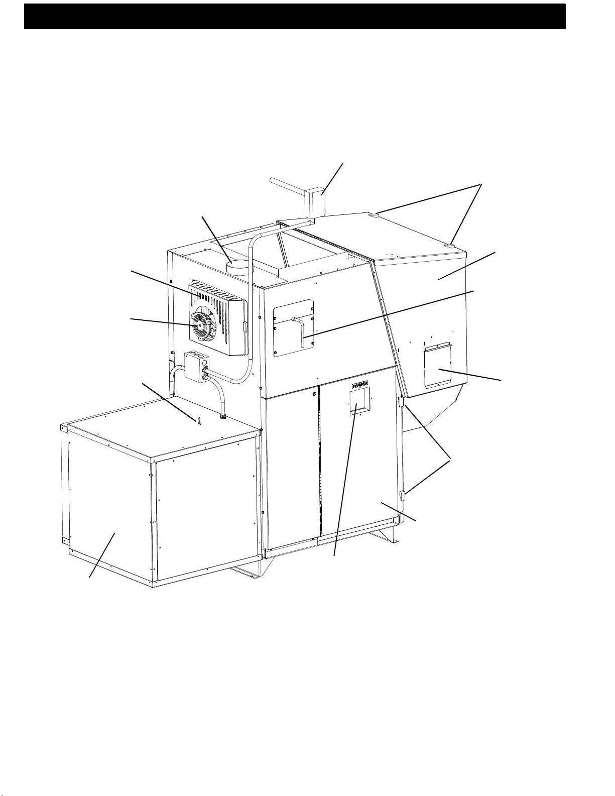
Vent Pipe
PF100 Parts
Fan Control
Hopper Lid
Latches
Combustion
Blower cover
Combustion
Blower
3 Speed Switch
Hopper
Heat Exchanger
Shaker Handle
Control Cover
Outer Door Latches
Outer Door
2
Viewing Glass
Filter Box
PF100
Page 3

Table of Contents
Assembly 4
Venting 10
Installation 15
Operation 21
Maintenance 29
Troubleshooting 34
Feeder Parts 3 5
Specifications 36
Wiring Diagram 37
Parts List & Options 38
Warranty 39
Testing Label 40
Quick Reference Start-Up 41
Please read this entire manual before you install and use your new
furnace. Failure to follow instructions may result in
property damage, bodily injury, or even death.
DO NOT INSTALL IN A MOBILE HOME.
SAVE THESE INSTRUCTIONS
Harman Stove Company
352 Mountain House Road
Halifax, PA 17032
3PF100
Page 4
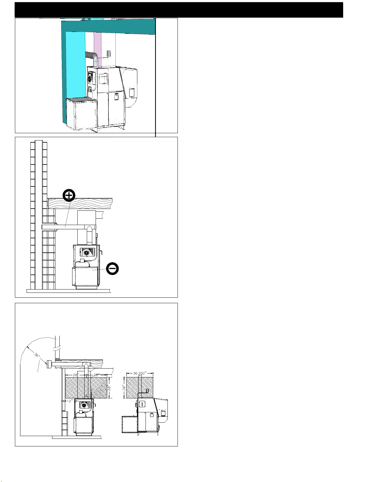
Fig. 1
Fig. 2
Assembly
Design
The first thing that needs to be done is deciding
where and how the furnace will be installed.
Things that need to be taken into consideration are
VENTING, SUPPLY& RETURN DUCTING, ELECTRICAL, and Condensation drainage (if A/C is in-
stalled). Don’t forget access to the furnace for service.
When the return air inlet position is known the filter
box and distribution blower can be installed. See pages
5, 6, 7, 8.
When the furnace is set into place venting can be
done.
Venting
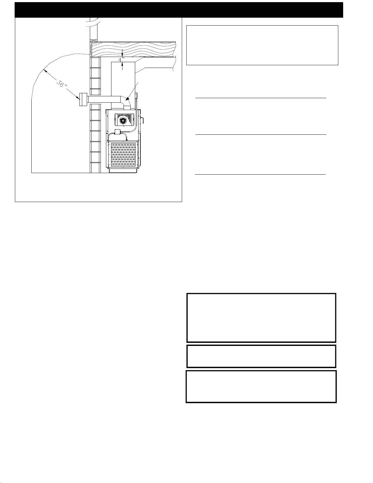
Use 4” pellet vent pipe to vent your PF 100.
A combustion blower is used to extract the combustion gases from the firebox. This creates a negative
pressure in the firebox and a positive pressure in the
venting system as shown in fig. 2. The longer the vent
pipe and more elbows used in the system, the greater
the flow resistance. Because of these facts we recommend using as few elbows as possible and 30 feet or
less of vent pipe. The maximum horizontal run should
not exceed 18 feet.
Be sure to use wall and ceiling pass through
fittings (which are approved for pellet vent pipe )
when going through combustible materials. Be sure
to use a starting collar to attach the venting system to the
stove. The starting collar must be sealed to the
stove flue collar with high temp silicone caulking
or aluminum tape, and screwed into the stove flue
collar at least three (3) places.
Clearances and Venting
See NOTES:
on page 12
4
PF100
The shaded areas are the clearances for the PL vent pipe that must
be maintained at 3”. After the venting leaves the shaded area it may be
installed at 2” to com bu stible s.
(Only UL listed wall pass-throughs
and fire stops must be used.)
Vent Pipe
4” pellet venting pipe ( also known as PL vent ) is
constructed of two layers with air space between the
layers. This air space acts as an insulator and reduces
the outside surface temperature to allow a clearance to
combustibles of only 2 inches. This 2 inch clearance is
also approved by the pipe manufacturers. See images
on left. See page 14 (Fig. 24 and 26) for larger images.
The sections of pipe lock together to form an air
tight seal in most cases; however, in some cases a perfect seal is not achieved. For this reason and the fact
that the PF100 operates with a positive vent pressure,
we specify that all joints within the structure should
also be sealed with clear silicone.
NOTE:Use only 4” diameter type “L” or “PL”
venting system. Be sure to inspect and clean
exhaust venting system frequently.
Page 5
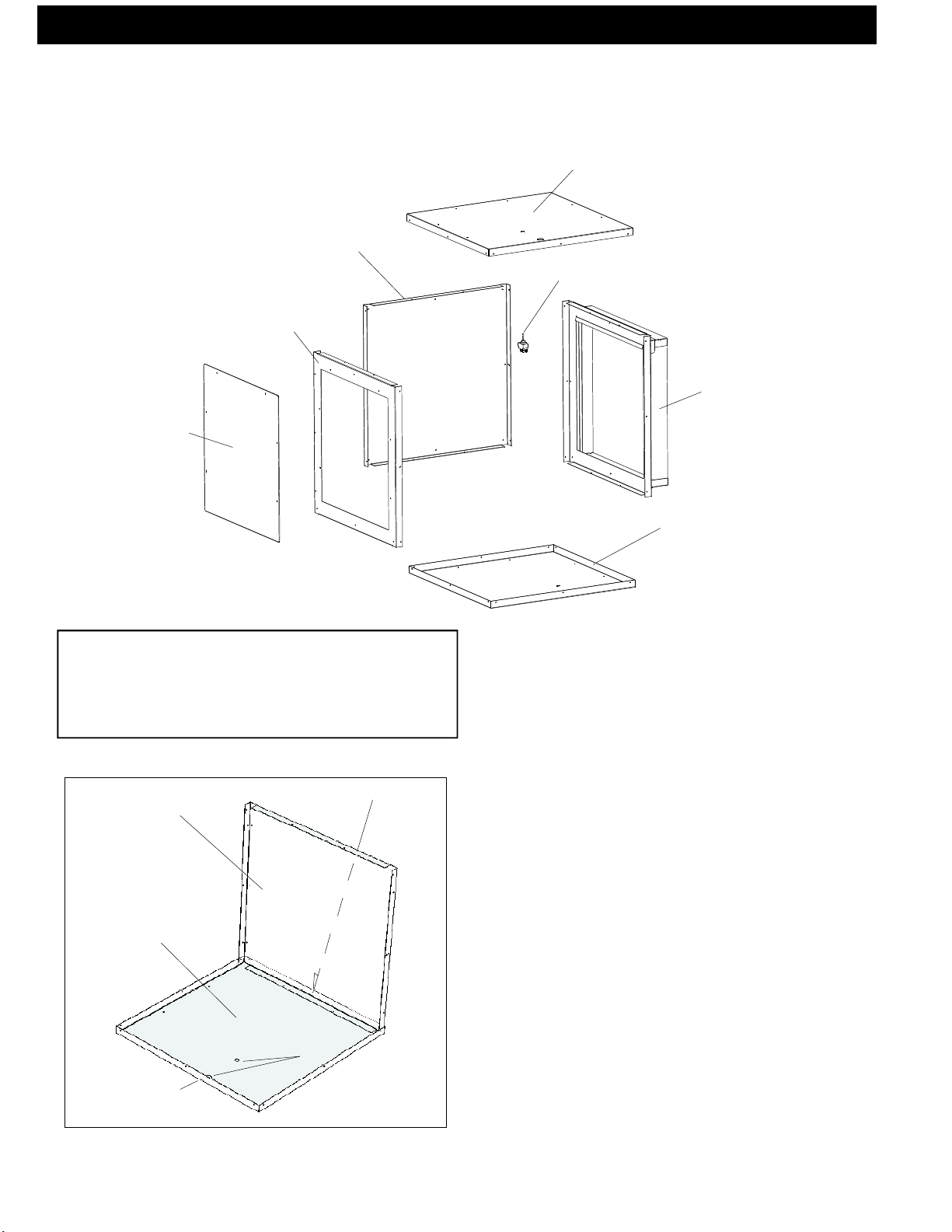
Blower access
Panel Cover
Assembly
Filter Box
(Cold Air Return)
Top (same as bottom)
Solid Side Panel
Switch
Blower access Panel
Filter Frame Panel
NOTE:Read and follow all of the vent pipe
manufacturers’ instructions on the proper
installation and support of the vent pipe. Adhere to
all clearances.
Tek screw from outside
Solid Side Panel
Bottom
Bottom (same as
top)
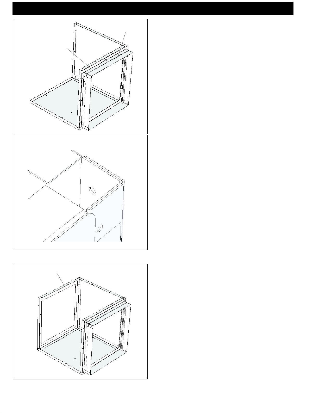
Fig. 3
Assembling Filter Box
The cold air return filter box can be assembled
with the filter frame on either side or the back, provided there is access to the combustion blower and flue
area.
It is not recomended that the filter frame be installed
on the same side as the ash door due to the need to
access the combustion blower, filter, and flue pipe for
service.
This Edge Toward
Furnace
Knockouts
Fig. 4
1. Place the bottom on the floor. The edge closest
to the knockouts will be the edge towards the furnace.
See Fig. 4.
2. Place the desired vertical panel inside the bottom tray and hold into place with one Tek screw in the
bottom middle hole. (solid panel shown) See Fig 4.
5PF100
Page 6
Assembly
Filter opening must be up
Filter Frame Panel
Fig. 5
Assembling Filter Box, Cont’d
3. Place the filter frame panel inside the bottom
and inside the solid panel corner. See Fig. 6 for corner
detail. Make sure that the filter opening is up.See Fig. 5
Hold the filter panel to the solid panel with a Tek screw
in the middle hole of the solid panel, and one in the bottom middle hole under the filter opening.
NOTE: Do not put any screws into any of the top
holes at this time.
Open Side Panel
6
PF100
Fig. 6
4. Place the remaining panel, (in this case the
blower access panel) in the bottom panel and into the
corner of the solid panel. See Fig. 7. Make sure that the
panel is in the upright position. There are no cover mounting holes in the bottom edge of this panel. Hold the panel
into place with one Tek screw in the middle hole of the
solid panel and one in the bottom middle hole of the
blower access panel.
Fig. 7
Page 7
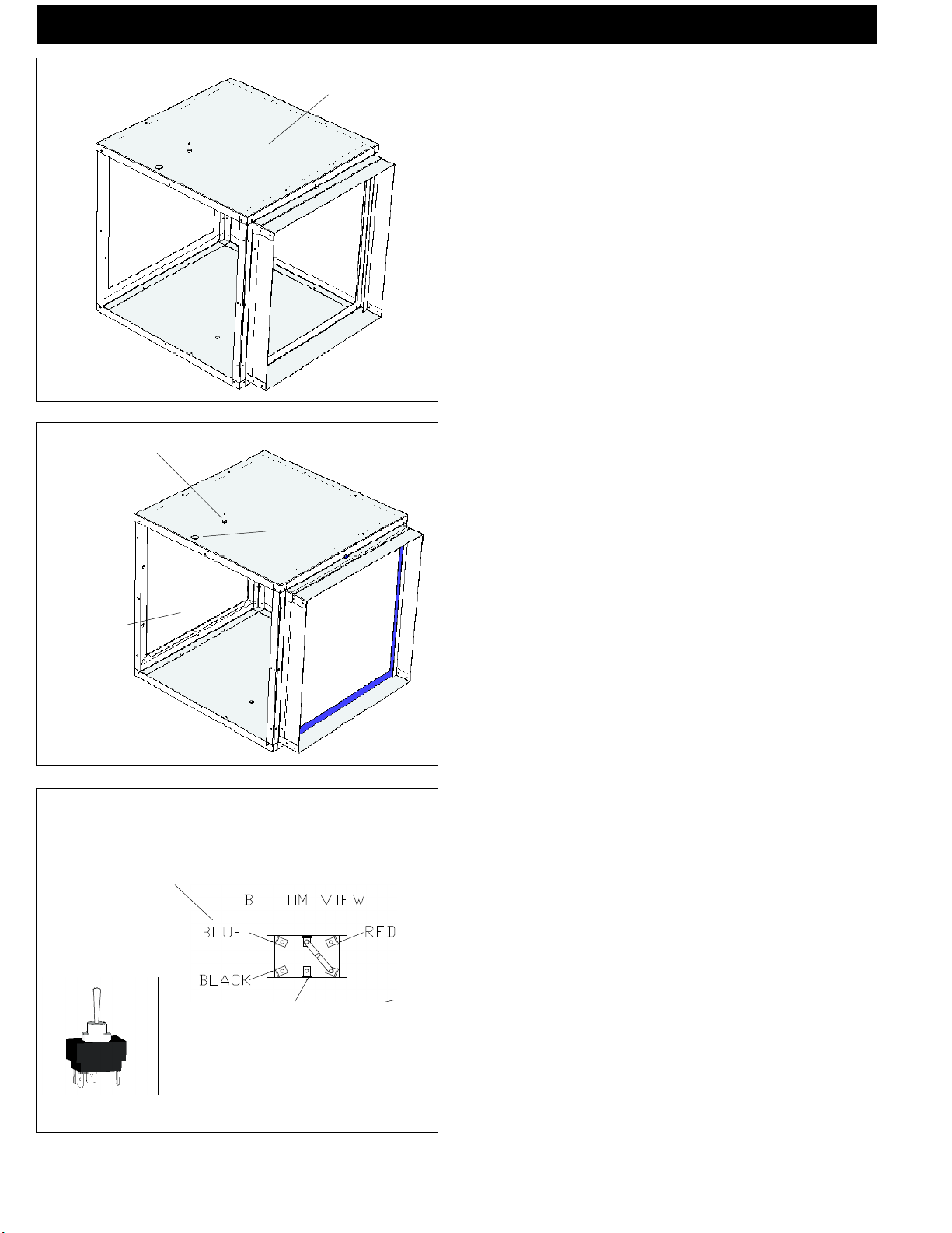
Top
Assembly
Assembling Filter Box, Cont’d
5. Place the top on the filter box as shown in figure 8. At
this time all Tek screws can be inserted around the filter
box.
Note: Except for the (6) screws that attach the
blower access panel in place. There should not be any
screws protruding from the box on the side toward the
furnace. Also DO NOT put a screw into the top center
of the filter panel as a screw in this location will interfere
with the filter access cover.
6. Pry out the two knockouts in the top of the box
and install the flex connector and the switch. See Fig. 9.
3 Speed Switch
Access Panel
Cover opening
Yellow on 2000 CFM motor
Flex connector
Fig. 8
Fig. 9
Note: Don’t forget the HI-MED-LO switch label
on the switch before the locknut.Make sure that the setscrew on the flex connector is not pointing toward the
furnace end of the box when the locknut is fully
tightened.The filter box is now ready to install onto the
furnace.
Follow the Blower mounting instructions on page
8 before continuing to step #7.
Note: The blower should be mounted on the furnace before the filter box for ease of distribution blower
installation.
Note: It is best to wait until the blower , filter box,
and cold air return duct work is installed before installing the filter and side panel.
7. After the Filter Box is installed on the furnace
the electrical wiring to the three speed switch needs to
be completed. WHITE to WHITE, VIOLET to the
center terminal of the switch, and the BLACK, RED,
BLUE to the terminals shown.
Note: The optional 1500 CFM blower is a single
speed blower, therefore the three speed switch will not
be used. The optional 2000CFM blower is a 4 speed,
only hook up the three colors shown and tape off the
orange wire. See Fig. 10.
Violet 120VAC
Fig. 10
8. Install the access panel cover by hooking the lip
at the bottom of the cover over the edge in the filter box.
Use 6 Tek screws to secure the access panel.
9. To install the filter, insert the filter into the filter
slot and slide completely into the frame. Take note to
the air flow arrow on the filter when installing.Slide the
filter access cover over the opening with the upright angle
toward the filter box. If a Tek was put into the middle
hole by mistake, remove the screw to allow the access
cover to fit properly.
7PF100
Page 8
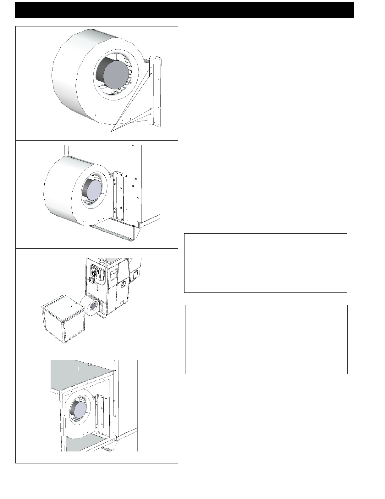
Mounting Screws
Assembly
Blower Assembly
Install the blower mounting brackets on the blower
as shown in Fig. 11.
1. Install ( 4) Tek screws on each side where shown
in Fig. 11. Start with the two center screws.
NOTE: There are two small holes in the discharge
end of the blower that match the two center holes on the
small angle of the blower bracket. The two (2) outer
holes are drilled by theTek screws.
Fig. 11
2. Mount blower with brackets installed on the
furnace as shown in Fig. 12. Each side will require 6
Tek screws.
NOTE: The furnace blower opening is made large
enough for the use of a 1500 or 2000 CFM blower.
The blower mounting brackets will fit either blower. The
inner hole pattern is for the 1000 CFM blower and the
outer pattern is for the 1500 or 2000 CFM blower.
8
PF100
Fig. 12
Fig. 13
Fig. 14
NOTE: These Blower Motors are not designed to
be operated without any positive static back
pressure. OPERATION WITHOUT SUPPLY
DUCTWORK OR IN FREE AIR WILL CAUSE
MOTOR OVERLOAD AND PREMATURE
FAILURE.
CAUTION: Regardless of the supply air duct size
installed, the Distribution Blower Motor MUST be
checked for running Amperage. Check the motor name
plate for the full load AMPS. If the amperage is running
higher than that listed, a supply air restricting damper
may be required to increase the supply plenum positive
static pressure.
3. Mount the filter box on the furnace with ( 8 )
10 x 3/4 Tek screws, 3 on each side. Visually locate
these holes so you are familiar with their location on the
filter box and the furnace. Access to the mounting holes
can be gained through the blower access panel cover
and the filter opening. See Fig. 14.
Note: Two pieces of 2x4 stacked laying flat on
the floor 12 inches from the blower opening will support
the filter box during installation.
Page 9
Assembly
Firebrick
Fig. 15
Firebrick installation-required
The firebrick is shipped in the ashpan. It will need
to be placed on the brick shelf as shown in Fig. 15. It
can be installed with either face to the fire. Hold the
brick longways and slide it down into the slot on the
shelf. There is a stop at the rear of the shelf to stop the
rearward travel.The brick just sits on the shelf in the
upright position.
Baffle installation
The upper heat exchanger baffle comes shipped
along side the ashpan. Remove the ashpan and the baffle.
This upper baffle needs to be installed before operating
the furnace.
Fig. 16
Baffle support bracket
Upper heat
exchanger baffle
45o bend
The baffle has a long 45 degree bend on the bottom of the firebox side. See Fig. 17.
The top has a 90 degree bend on the same side to
use as a handle.
On the opposite side there are four hooks that will
support the baffle.
On the front and rear of the firebox walls there are
brackets that these hooks fit into. See Fig. 16
Slide the upper baffle down on to the brackets,
while you hold the baffle against the heat exchanger. You
will notice that the upper baffle will hold the lower baffle
plate into position. See Fig.17.
Note how the upper and lower baffles are held
into position because they will need to be removed
during heat exchanger cleaning.
Fig. 17
9PF100
Page 10
Venting
Venting
NOTE: Use only 4” diameter type “L” or “PL”
venting system. Be sure to inspect and clean
exhaust venting system frequently.
4” Type “L” or
“PL” Vent pipe
Fig. 18
This is the minimum venting configuration.
NOT E : T his would only b e a llowed with non-
combustible walls.
The minimum vent configuration is a 90o or Tee on
a starter collar and a 24” length horizontal through an
exterior wall. A cap or other bird screen on the end
should direct the flue gasses down and away from the
structure. See Fig. 18.
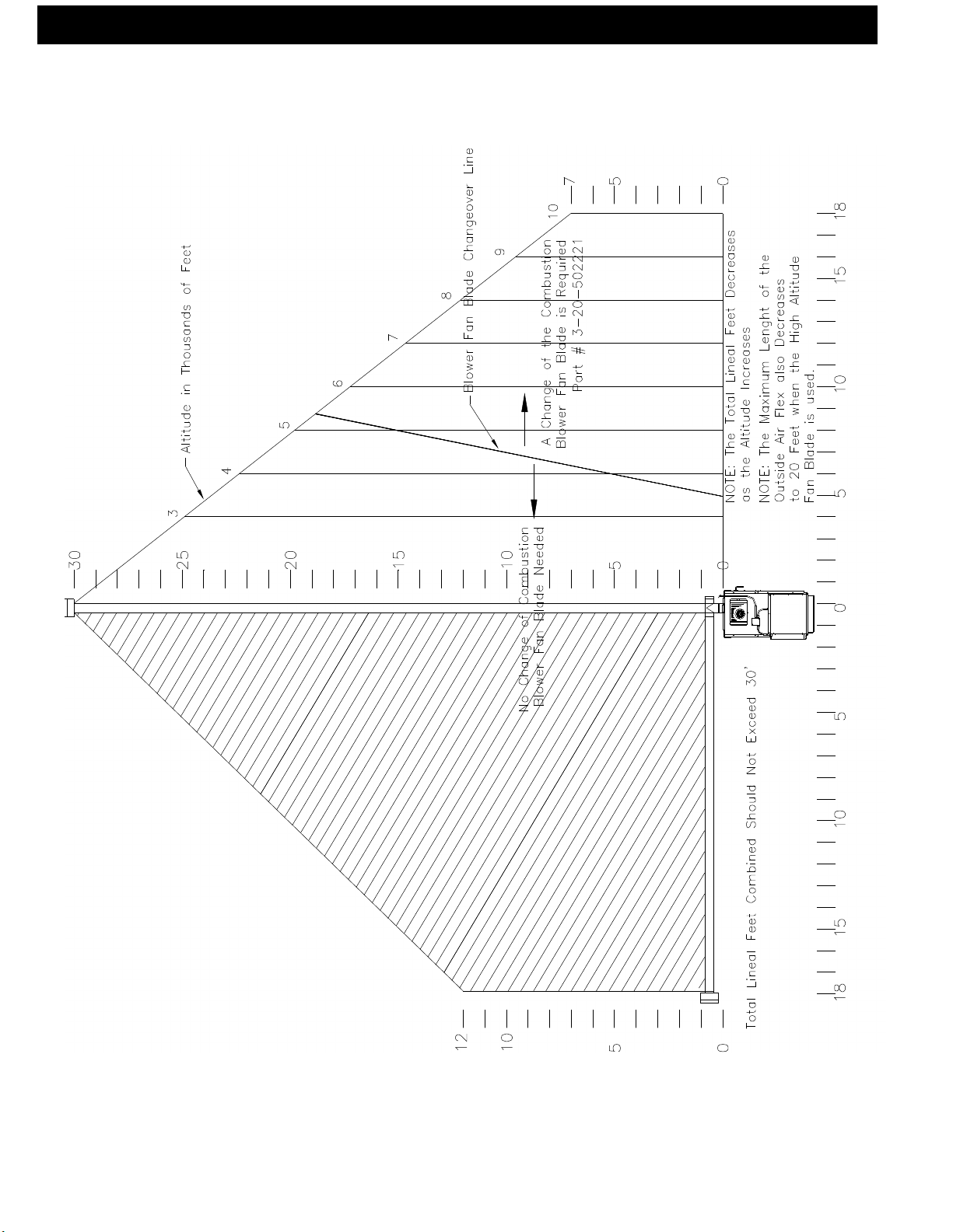
The maximum horizontal length is 18 feet. The mini-
mum termination height above the exterior grade is 18”.
The maximum total length of any configuration is 30 feet*.
* ( see venting graph on page 13 for exceptions )
NOTE: Cleanout Tee’s should always be used on
the transitions to horizontal pipe to allow easy access
for cleaning.
The venting gragh allows for (one) 90 deg. or Tee
fitting in any configuration.
If more 90’s, T’s, or 45’s are needed the total length
must be adjusted to allow for the added restriction.
Up to four (4) additional 90’s, Tee’s, or equivalent
45’s can be added as long as the overall length is ad-
justed in accordance with the values listed below.
( See the venting graph on page 12.)
Each Vertical ---- 90 deg. or T subtract 2.5 feet
Each Vertical ---- 45 deg. subtract 1.5 feet
Each Horizontal - 90 deg. or T subtract 5.0 feet
Each Horizontal - 45 deg. subtract 2.5 feet
Any exterior venting (vent pipe exposed to outside ambiant temperatures) should be kept to a
minimum, due to potential condensation problems.
This is especially important in high humidity cold
weather climates, such as maritime areas, lake shores,
and low river valleys.
INSTALLATION IS TO BE PERFORMED BY A
QUALIFIED INSTALLER.
DO NOT INSTALL A FLUE DAMPER IN THE
EXHAUST VENTING SYSTEM OF THIS UNIT.
DO NOT CONN ECT THIS UNIT TO A
CHIM NEY FLUE S ERVING ANOTHER
APPLIANCE.
INSTALL VENT WALL PASS-THROUGHS AT
CLEARANCES SPECIFIED BY THE VENT
MANUFACTURER
NOTE: All installation clearnaces and restrictions
must be adhered to.
NOTE: Read and follow all of the vent pipe
manufacturers’ instructions on the proper
installation and support of the vent pipe. Adhere to
all clearances.
WARNING
Keep combustible materials such as grass, leaves, etc.
at least 3 feet away from the point directly under the
vent termination. (between the vent and the ground)
WARNING
DO NOT INSTALL IN SLEEPING ROOM
CAUTION
KEEP COMBUSTIBLES AWAY
FROM FLUE OUTLET.
10
PF100
Page 11
Venting
Fig. 19
Venting Configuration Graph
11PF100
Page 12
Venting
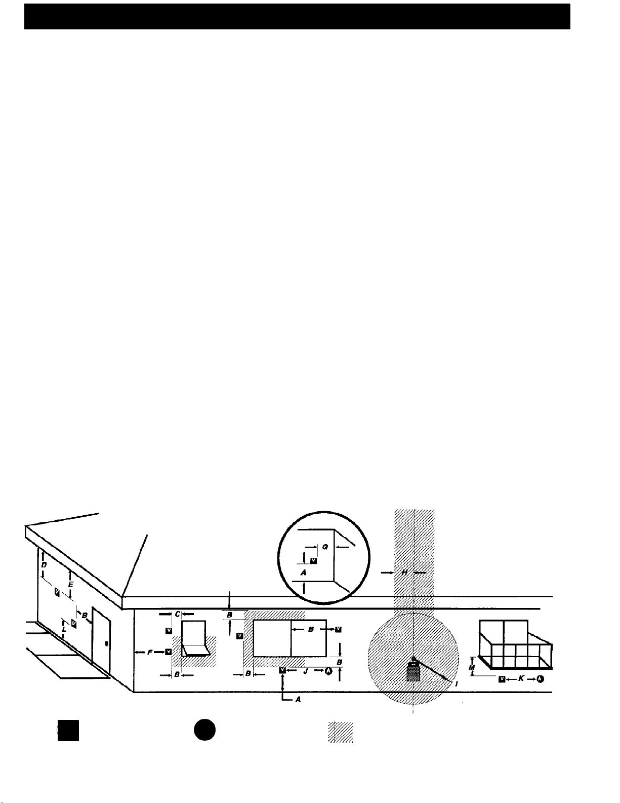
Requirements for Terminating the Venting
WARNING: Venting terminals must not be recessed
into a wall or siding.
NOTE: Only PL vent pipe wall pass-throughs and
fire stops should be used when venting through combustible materials.
NOTE: Always take into consideration the effect
the prevailing wind direction or other wind currents will
cause with flyash and /or smoke when placing the termination.
In addition, the following must be observed:
A. The clearance above grade must be a minimum
of 18".
1
B. The clearance to a window or door that may
be opened must be a minimum of 48" to the side, 48"
below the window/door, and 12" above the window/
1
door.
( with outside air installed, 18” )
C. A 12" clearance to a permanently closed window is recommended to prevent condensation on the
window.
D. The vertical clearance to a ventilated soffit located above the terminal within a horizontal distance of
2 feet (60 cm) from the center-line of the terminal must
be a minimum of 18".
E. The clearance to an unventilated soffit must be
a minimum of 12".
F. The clearance to an outside corner is 11" from
center of pipe.
G. The clearance to an inside corner is 12".
H. A vent must not be installed within 3 feet (90
cm) above a gas meter/regulator assembly when measured from the horizontal center-line of the regulator.
1
I. The clearance to service regulator vent outlet
must be a minimum of 6 feet.
1
J. The clearance to a non-mechanical air supply
inlet to the building or the combustion air inlet to any
other appliance must be a minimum of 48”.
1
K. The clearance to a mechanical air supply inlet
must be a minimum of 10 feet.
1
(with outside air installed, 6 feet )
L. The clearance above a paved sidewalk or a
paved driveway located on public property must be a
minimum of 7 feet.
M. The clearance under a veranda, porch, deck
or balcony must be a minimum of 12 inches.
1,2
1,3
NOTE: The clearance to vegetation and other
exterior combustibles such as mulch is 36” as measured
from the center of the outlet or cap. This 36” radius
continues to grade or a minimum of 7 feet below the
outlet.
1
Certain Canadian and or Local codes or regula-
tions may require different clearances.
2
A vent shall not terminate directly above a sidewalk or paved driveway which is located between two
single family dwellings and serves both dwellings.
3
Only permitted if veranda, porch, deck, or balcony is fully open on a minimum of 2 sides beneath the
floor.
NOTE: Where passage through a wall, or partition
of combustible construction is desired, the
installation shall conform to CAN/CSA-B365. (if in
Canada)
12
V
PF100
= Vent terminal
Fixed
Closed
Openable
A
Openable
= Air supply inlet
Fixed
Closed
Inside
Corner
Detail
= Area where terminal is not permitted
Fig. 20
Page 13
Venting and Clearances
Floor Protector
PF100
Skidplate
Footprint
52” long
18”
48” wide
”
Fig.21
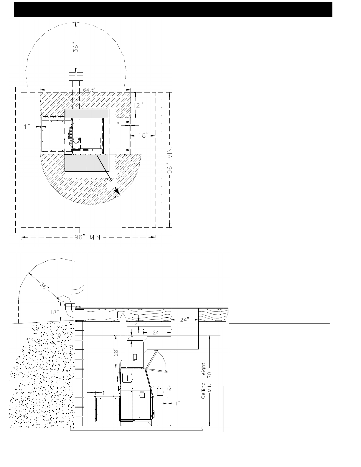
Clearances to combustibles
If installing the furnace in a room separated from the
remaining living spaces, the minimum size of the room must
be no smaller than 8’ x 8’. See Fig. 21. The reason for this
is heat build-up and required space for service and normal
operation.
This is the minimum size of the room even if it is built
of non-combustible material.
High and low air vents MUST be installed between
the room and the remaining living space. Each vent should
be at least 72 square inches in area. ( The vent size will
need to be increased if there is no return air ducting system.)
The striped areas are the minimum clearances to com-
bustibles which is 36” from stove body, not hopper or
blower.
The shaded area indicates the required floor protec-
tion area. The PF100 requires 48” x 52” of floor protec-
tion centered around the skidplate footprint. Flooring should
be a minimum of 26 gauge sheet metal covering the instal-
lation clearance area and 18” in front of, and 8” to either
side of the ash pan door.
The 18” clearance on the hopper end is a manufactur-
ers recommendation for adding pellets and or servicing the
feeder mechanism.
The minimum clearance to the top of the plenum is 4”.
Note the minimum height to the bottom of the supply
duct if it crosses the hopper.
The minimum duct configuration to a living space above
the furnace is as shown in below. An offset of at least 24”
MUST be installed between the plenum and the floor register. The register size MUST have an area of at least 240
square inches.
The minimum ceiling height is 6’6”. This is set by the
clearance to combustibles ( 28” ) from the top of the
of the furnace. See Fig. 22.
NOTE: Install vent at clearances
specified by the vent manufacturer.
Fig. 22
CAUTION: When installing a floor
register, the temperature of the
discharge air MUST be taken into
consideration (The discharge air
temperature may be high enough to
cause burns if not properly operated
and maintained.)
CAUTION: The Blower Motor full
load AMPS MUST be checked.A
plenum damper may be required to
adjust the motor full load AMPS to the
motor nameplate rating.
13PF100
Page 14

See NOTES: on
page 13
Venting and Installation
The shaded areas are the clearances for the PL vent
pipe that must be maintained at 3”. After the venting leaves
the shaded area it may be installed at 2” to combustibles.
(Only listed 4” pellet vent wall pass-throughs and fire stops
must be used.) See Fig. 23 & 25.
181/8” 181/8”
16
16
Fig. 23
Chimneys taller than 20’ above the connection will re-
quire a draft test to determine if the draft is too high.
Note: The High Burn Draft should not exceed .85
IWC. Some form of a restrictor plate may be required at the
top of high chimneys to reduce the draft. See page 20 for
the Draft Test procedure.
Fig. 25
The PF100 furnace may be used and installed into an
existing masonary or Class A metal chimney.
Certain Canadian and Local Codes may require that
the chimney be fully relined. See Fig. 24.
It Can Not be installed in a chimney serving another
appliance.
The chimney should be cleaned and or inspected be-
fore installation.
Fig. 26
Fig. 24
Creosote - Formation and Need for Removal - When wood is burned slowly, it produces tar and other organic vapors,
which combine with expelled moisture to form creosote. The creosote vapors condense in the relatively cool chimney flue
of a slow-burning fire. As a result, creosote residue accumulates on the flue lining. When ignited, this creosote makes an
extremely hot fire. The pellet vent pipe should be inspected at least twice monthly during the heating season to determine
if a creosote buildup has occurred. If creosote has accumulated it should be removed to reduce the risk of a chimney fire.
Guidance on minimizing creosote formation and the need for periodic creosote removal: The chimney should be
inspected during the heating season to determine if a creosote build-up has occurred. If a significant layer of creosote has
accumulated (3mm or more) it should be removed to reduce the risk of a chimney fire.
14
PF100
Page 15

Installation
Inlet Cover part#
1-10-09542
Fig. 27
Outside Air Pipe Knockout
Fig. 28
Outside Air Inlet Pipe
Outside Air
Outside air is optional, although it may be required
by some building codes. The benefit of outside air is
higher efficiency and reduced venting restrictions mainly
noticed in small and very tight houses.
To install outside air, use 2 3/4”" I.D.galvinized steel
flex pipe, part # 2-00-08544 ( 12’ 6” length) or part #
2-00-08545 ( 25’ length). There is a break-away hole
on the rear panel which must be removed before connecting the flex pipe. See Fig. 28. The pipe should be
run outside and terminate 3 feet or more below or 1
foot or more to the side of the vent pipe outlet. Never
terminate the outside air above the vent pipe outlet. The
maximum length of this pipe is 25 feet. Inlet cover part
number 1-10-09542 should be used to keep birds, rodents etc.out of the inlet pipe. See Fig. 27.
NOTE: If outside air is installed, the inlet cover
should not be placed in an area where drifting of snow
or ice will build up, blocking the intake air supply.
The Outside Air knockout is located on the face
of the Feeder Cover. It is pre-cut except for several
small tabs. There is also a filler plate screwed to the
inside to cover the top of the hole after the Outside Air
Pipe has been installed. This will allow for removal of
the Feeder Cover without disconnecting the Outside Air
Pipe. See Fig. 28.
Only metal Intake Flex should be used for the
Outside Air Supply connection.
Only a screened or rodent protected Outside Air
Intake cover should be used as an outside weather cover.
The Outside Air Intake Pipe is inside the Feeder
Cover and to the right of the feeder motor. The 2 3/4”
steel flex pipe is made to slide over the outside of the Air
Intake Pipe. See Fig. 29. It should be held into place
with some silicone, foil tape, or a hose clamp. ( not supplied )
Fig. 29
HRV
When installing in a house with a Heat Reclaiming
Ventilation System (HRV) be sure the system is balanced
and is not creating a negative pressure in the house.
Note: If the furnace is installed with the outside air
system no adjustments to the HRV should be necessary.
15PF100
Page 16

Installation
70
65
60
Fig. 30
Fig. 31
Datacom Wall Control
Cable
Orange - Red (+ LED )
Blue/White - Blue ( Tstat )
Orange/White - White or Black ( - LED)
Blue - Blue ( Tstat )
Fig. 32
75
L
F
80
OW
UEL
Wall Control Wiring
The Wall Control sends and receives it’s informa-
tion from the control board through a 4 wire Datacom
cable. There is a 100’ length of this cable supplied with
the furnace. 100’ lengths of this cable can also be or-
dered separately, part # 3-20-02583. Or any Datacom
cable -CAT 3 - 2 twisted pair 24ga solid wire can be
acquired at a local electrical supply house. Also any CAT
3- 24ga. solid wire 2, 3, or 4 pair cable can be used
because they all have the same pair color combinations.
The maximum length of wall control wiring is 200 feet.
The furnace connecting point is a 4 pole screw terminal block on the side of the hopper just around the
corner to the right of the control. Follow the wiring
instructions on the label alongside the terminal block.
See Fig. 31.
CAUTION: With this small of wire gauge, care
must be taken not to overtighten the terminal screws,
thus breaking the wire.
There are tie-wrap holes in the face of the hopper
aprox. every 6” to keep the cable secure and out of the
way.
The Wall Control is made to fit on a standard wall
case electrical box. It could also be mounted directly to
a stud using 2 drywall screws. In either case the screws
should be turned in and tested for a snug fit when the
Wall Control is slid down over the screws. The Wall
Control only hangs on the screws so a good fit is important.
Remove the Wall Control and make the Datacom
cable connections with the UY auto splicers provided.
DO NOT STRIP THE WIRES. Following the wiring
diagram on the inside of the Wall Control make each
splice. See Fig. 32. Insert the two matching color wires
fully into the two holes of one of the UY connectors. A
pair of standard Channel-lock pliers works ideally to
squeeze the raised button down into the UY connector
body. Extra UY connectors can be purchased.
Part # 3-20-00200
NOTE: A pair of needle nose pliers may be necessary to insert the BLUE T-stat wires fully into the connector. Visually inspect to see that the wires are fully
inserted before squeezing the UY splicer.
16
NOTE: The PF100 furnace Can Not be
installed with any other brand or type of wall
thermostat.
PF100
Page 17

Installing Duct
Installing Duct
The Harman PF100 may be connected to a gas or
oil-fired central furnace or heat pump duct system. Prior
to installation, determine whether all requirements for
installation including all clearnaces can be met.
The PF100 warm air supply and the cold air return
must be installed in a parallel arrangement. EXAMPLE:
The warm air supply duct from the PF100 is to be connected to the warm air supply of the existing furnace.
Also the cold air return duct from the existing furnace is
to be connected to the cold air return duct of the PF100.
Isolation dampers (2) should be installed in the ductwork.
(1) in the warm air supply duct for the existing furnace
and (1) in the warm air supply duct of the PF100 after
or “downstream” of the high limit/fan control. These
dampers can be manually operated or fully automatic.
In either case, the unit that is not being used must be
prevented from being operated. (This also can be done
Fig. 33
manually or automatically.) NOTE: Any control wiring,
power wiring needed should be performed by a qualified installer and/or electrician.
The warm-air supply outlet of the PF100 shall not
be connected to the cold-air return inlet of the central
furnace because a possibility exists of components of
the central furnace overheating and causing the central
furnace to operate other than as intended.
We recommend that the warm air supply plenum
be constructed of sheet metal.
17PF100
Page 18

Installing Duct/Air Conditioning
Installing Duct
Recommendations for Supply Air and Return Air
duct sizing.
The speed or velocity of air moving through duct
systems increases as the duct decreases in size with the
same CFM blower. The sound of air flowing through
the duct increases as the velocity increases. Therefore
the largest size duct practial should be used.
The velocity to sound level must be taken into consideration when connecting this furnace into an existing
duct sustem.
As a primary source furnace the duct system can
be installed to fit the customers needs.
These are recommended Supply Air duct sizes (in
square inches)for the different CFM blowers that may
be used with this furnace.
Velocity 500fpm 700fpm 900fpm Static
I.W.C. .3 min. to .6 max.
1000CFM 270sq.in 210sq.in. 160sq.in.
1500CFM 360sq.in. 290sq.in. 220sq.in.
2000CFM 470sq.in. 360sq.in. 290sq.in.
(These duct sizes are only recommendations. )
The Return Air duct system should be sized aprox.
10 percent larger for heating only systems and 20 percent larger if airconditioning is installed.
Adding Air Conditioning to the PF100 furnace.
An easy rule of thumb for A/C CFM blower size
is, .75 to 1 CFM for each square foot of conditioned
space. (std. 8’ ceiling height )
The PF100 furnace can be fitted with an air condi-
tioning coil mounted in the supply air plenum.
The Harman Stove Co. is not responsable for
sizing,duct placement, or interconnections. However we
have made adding A/C to the furnace easier with the
information listed below.
There is a factory installed junction box ready to
accept your A/C relay. The A/C fan control center with
40 va transformer must have a DPDT relay.
STEVECO # 90-112 - Harman part # 3-20-38056
Other brands are available at local supply houses.
The wiring should be done as per Fig. 34. The low
voltage wiring to the outside condensing unit and the
cooling thermostat are not shown, see condensing unit
diagrams for that information.
This style relay is used to lock out the feeder system of the furnace when the A/C unit is calling for cooling. This is a fail-safe against both units operating at the
same time. See the NOTE in the lower left corner.
CAUTION: Regardless of the supply air duct
size installed the Distribution Blower Motor MUST be
checked for running Amperage. Check the motor name
plate for the full load AMPS. If the amperage is running
higher than that listed, a supply air restricting damper
may be required to increase the supply plenum positive
static pressure.
It is highly recomended that the
furnace control be turned to the
“OFF” posit ion whenever air
conditioning is being used, whether
or not it is interconnected.
NOTE:
18
Fig.34
PF100
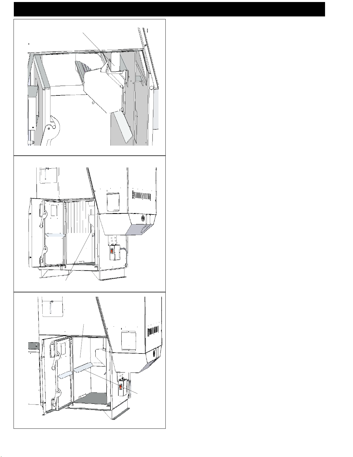
Page 19

Installation
High limit fan control
Fig. 35
Fan Control
Setpoint
FAN/HIGH LIMIT CONTROL
Installation & Set-up
1. The Fan Control must be placed in the discharge
plenum approximately 11 inches above the discharge opening of the furnace as close to center as possible.
Note: The best place is on the same side as the ash
door because of ease of access. See Fig. 35.
Note: Care must be taken when installing the Fan
Control when an air conditioning A Coil is used. The Fan
Control must always be installed below the A Coil in low
plenum installations.
2. Install the flex and wiring.
3. Make sure that the flue venting will not interfere
with the flex to the Fan Control.
4. Pry out one of the bottom knockouts of the Fan
Control. Install the 90 degree flex connector as shown in
Fig. 36. One of the locknuts stays on the outside of the
box and one goes on the inside to tighten the connector
into place. This allows for maximum room for the wires
around the switches.
Setpoint
High Limit
CONTROL
LIMIT
Fig. 36
Locknuts outside and inside
NOTE: KEEP THE FAN/LIMIT CONTROL
IN STRUCTIO NS W ITH THE OWNERS
MANUAL FOR FUTURE REFERENCE.
NOTE: If fans are used in the fuel storage area,
they should be installed so as not to create negative
pressures in the room where the solid-fuel-burning
appliance is located.
5. REMOVE THE COPPER JUMPER BETW EEN TH E LIMIT AND CONTROL
SWITCHES. (It is not needed.) Figure 36 shown with
copper jumper that has already been removed.
6. Connect the two VIOLET wires to the FAN
CONTROL switch. ( It doesn’t matter which wire is on
which screw). See Fig. 36.
7. Connect the WHITE and SKY BLUE wires to
the LIMIT switch. ( It doesn’t matter which wire is on
which screw). See Fig. 36.
8. Make sure that all of the wires are out of the way
when closing the cover. ( Excess twisting and pinching of
the wires could cause a short circuit.)
9. HIGH LIMIT setup is simple, just rotate the high
limit pointer clockwise until it is against the tamper-proof
screw. (Never adjust this screw)
10. FAN CONTROL setup: Move both fan control
pointers together until they touch, then rotate both pointers
together until the gap between them is directly over the
middle 0 of 100. See Fig 36.
Note: This is the best fan control position we have
found during factory testing. These fan control limits can
be adjusted if desired.
19PF100
Page 20

Draft meter bolt
20
PF100
Furnace Control
Installation
“Test”
Low Draft Adjustment Pot
Fig. 37
Fig. 38
Fig.39
Installing Electrical Power:
To install power to the furnace first remove the cover
on the circuit breaker junction box shown.
Inside you will find the main terminal block.(See wiring diagram on page 36 for location of main terminal block
and proper power connections). In the bottom of the box a
knockout hole is provided for the incoming wire.
The minimum recommended circuit is 15 Amp 120
V.A.C. 60 Hz. This furnace should be the only appliance
on the circuit.
This furnace should never be powered by the use
of an extension cord.
The recommended high and low voltages are, 130
V.A.C. 60 Hz maximum high voltage, and 113 V.A.C. 60
Hz minimum low voltage.
The furnace will continue to operate at voltages as
low as 105 V.A.C. , although it can not be guaranteed that
automatic ignition will occur. Also there is the possibility of
a distribution blower motor overload.
NOTE: If other sources of electrical power are
to be used ( such as a generator ) for normal operation or emergency operation, this source should be
checked before installation. Many generators and
inverters may not supply 120V.A.C. 60Hz. power
stable enough to operate the control board properly.
(Control board damage could occur). Checking & Recording the Low Draft:
After the venting is completed, the firebox low draft
will need to be checked and possibly adjusted. After re-
moving the 3/8” bolt from the draft hole shown in Fig. 38,
insert the draft meter tube. The inner ash door and the
hopper lid must be latched during this test. ( It is recom-
mended that the draft meter have a scale of 0 to 1” WC.)
Turn the Furnace Control to “Test”. this will start the
combustion blower and allow you to check and record the
High Draft ______ - IWC date _______ (There is no
adjustment for the High Draft)
After the first 60 seconds the “Test” mode lowers the
combustion blower voltage to the Low Burn voltage. (The
“Test” mode cycles the voltage from high to low every 60
seconds).During this lowered voltage cycle the Low Burn
Draft must be checked and adjusted if necessary. The
recommended low draft setting should be between -.25 &
-.35 IWC. Depending on the amount of vertical rise, it may
not be possible to get a low draft reading in this range. In
this case, a maximum low draft of -.55 is acceptable.
The adjustment screw is through the small hole to the
right of the Igniter Light. See Fig. 39. Adjusted the Low
Draft to __________ -IWC.
Don’t forget to turn the control back to #4.
Page 21

Operation
Combustion
blower cover
Combustion
Blower
3 Speed Switch
Vent Pipe
Fan Control
Hopper Lid
Latches
Hopper
Heat Exchanger
Shaker Handle
Control Cover
Outer Door Latches
Outer Door
Filter Box
Viewing Glass
Fig. 40
The Control
The control can be covered as shown above, or
uncovered as shown at left. There is a pair of slots provided for each position. Simply move the cover to the
desired position by placing the tabs on the cover in the
proper slots.
CAUTION: Hot while in operation. Do
not touch. Keep childre n, clothing,
furniture, and other combustible material
out of the installation clearance area.
WARNING: Do not operate with fire
chamber or ash removal doors open.
Fig. 41
WARNING: Do not store fuel or other
combustible material within installation
clearance area.
21PF100
Page 22

Operation
Power Light
Indicates power to t h e
control, and is also used
during “Test” to check the
Low Fuel Sensor operation.
Status Light
Wil l be lit in ei ther
automatic or service mode
when pointer is not within
off position band except
after normal shut down.It
also b links to indica t e
errors listed below.
Low Fuel Light
Indi c ates that fue l in the
hopper is low and needs to be
refilled.
Combustion Blower Light
Indicates Power to
combustion blower
IGNIT OR
Feed adjuster
Sets the maximum feed rate
Test
Runs all motors ** at full speed
for one minut e t o c heck
operation. After one minute the
furnace will go to minimum
burn and t he c ombu stion
blower will alternate from high
to low every minute to remind
you that you are still in "Test
Mode".
Lighting Mode Selector
Switched between Auto and
Manual lighting
Mode Selector
See explanation below.
Feed Motor Light Indicates
Power to the feed motor.
IgnitEr Light
Indicates power to the
ignitor
Status light error messages:
1 Blink: Indicates control board self diagnostic failure. This
requires a manual reset*.
3 Blinks: Indicates ESP (Exhaust Sensing Probe) failure. This
requires a manual reset*.
4 Blinks: Can occur only in the Automatic Mode and
indicates the Wall Control has failed or is not installed. If a
Wall control is then installed the status light will automatically
reset.(Note) only after the unit has warmed up.
5 Blinks: (In Auto Light Mode Only)
Indicates that the igniter has failed to light the fire after 4
consecutive 8 minute attempts. To reset - Turn the Mode
Selector to OFF and then back to Automatic.
6 Blinks : Indicates that the control has calculated poor or
incomplete combustion occurring for more than 50 minutes.
A six blink status may be set if the stove is allowed to run out
of pellets. To reset, turn mode selector to "OFF" then back
on to the desired mode. If the unit was not out of pellets, see
Troubleshooting section, Page 35, for more details.
* Manual reset, disconnect power at the circut breaker for
a few seconds and reconnect. If error still occurs call your
Dealer.
22
PF100
Temp dial
The “Temp Dial” should be in the “Normal Setting” position except when
service work is being done. It also allows you to adjust the fire temperature
when the “Mode Selector” is in “ Service Mode” using the scale marked
from 1 to 7.
...
...
Fig. 42
Mode Selector
Allows you to choose between Automatic Mode, Service Mode
or OFF.
Automatic Mode
Automatic mode switches operational control of the furnace
to the wall mounted control. This is the mode to use whenever
the furnace is burning in a normal heating application.
Service Mode
Service mode switches control of the furnace to the temp
dial. The temp dial can be set from 1 to 7 to allow a steady
furnace temperature at the desired level. The main purpose
of this mode is to operate the furnace without having to go
back to the wall mounted control.
OFF Mode
Turning the mode selector to OFF will shut down the furnace.
** The Distribution Blower is not controlled by the “Test”
operation. The Distribution Blower has it’s own Manual Test
Switch on the Fan / High Limit Control cover.
Dealer Diagnostic Port
For dealer maintenance only.
Requires special DDM monitor
supplied to Harman Dealers
exclusively.
Page 23

65
60
70
75
L
F
80
OW
UEL
Operation
Temperature Dial
Low Fuel Light
Fig. 43
Wall Control
The wall control acts like a thermostat, however,
what is actually going on is a thermister in the wall control is sending temperature information back to the micro processor on the furnace. This information is used
to increase or decrease the size of the fire according to
the needs of the home.
Setting The Room Temperature
To set the room temperature, simply turn the temperature dial to the desired setting. The control and the
furnace will then perform to achieve the set temperature.
Note: The minimum temperature you can set with
a full counter-clockwise knob position is 58 degrees.
The maximum temperature you can set with a full clockwise knob position is 90 degrees.
Wall Control calibration: The “Normal Setting” on
the Temp Dial of the Furnace Control (See Fig.44) calibrates the Wall Control temperature span.If the Temp
Dial is not pointing to the “Normal Setting”, the tem-
perature span could vary by 3 degrees up or down depending on the Temp Dial knob setting.
Fig. 44
Low Fuel
Sensor
Fig. 45
Low Fuel Sensor
There is a low fuel sensor in the hopper that tells
the control that the fuel level in the hopper has dropped
below the sensor. When this happens, the Low Fuel light
on the Wall Control will start to blink.You then know
that it is time to fill the hopper with pellets.
Note: Testing the low fuel sensor can be done by
turning the FEED ADJUSTER knob to “Test”. The
POWER light will go off when the sensor is uncovered
and will light when the sensor is covered again.
Note: The LOW FUEL light on the Furnace Control will light at the same time. Only the LOW FUEL
light on the Furnace Control will remain lit for three minutes after the sensor is covered with pellets. See Note
below.
Note: The Low Fuel light indicates that there is
power going to the auxiliary leads in the circuit breaker
junction box. (120 VAC 60 Hz Max. 1 Amp.)
The auxiliary power leads would be used if an
optional bulk hopper and auger system were installed.
(see wiring diagram on page 36)
Type of Fuel
Pelletized wood only. Note: The lower the ash
content of the pellets the less cleaning that will be needed
of the heat exchanger surfaces. The cleaner these surfaces
are kept, the more efficient the furnace will be.
23PF100
Page 24

Operation
Fig. 46
Starting A Fire Automatically
1. Turn Mode Selector to "OFF".
This resets the control in addition to turning it off.
2. Fill hopper with pellets.
When filling the hopper check for excessive fines in
the bottom of the hopper. Fines are small pieces of broken
pellets (sawdust). Fines do not flow easily and often build
up on the hopper funnel bottom angles. These fines can
be pushed into the feeder opening and then fill the hopper
with pellets. As the system works, they will be burned.
24
Fig. 47
3. Clean burnpot with scraper, if necessary.
This is usually a weekly maintenance procedure.
Cleaning the burn pot with the scraper with a small amount
of new fuel in the bottom is not a problem. First, scrape
the ashes on the front of the burn pot into the ash pan.
Then scrape the hole grid surface downward into the
burn pot. When the stove is ignited these scrapings will
be pushed out by the feeder.
Note: If the Distribution Blower is running when
the outer door is open, some air will escape around the
door opening. This is not a problem, however, any dust
that is caused in the process can potentially be blown
around.
Fig. 48
PF100
Page 25

Operation
4. If starting after an empty hopper, turn
Feed Adjuster to "TEST" (for one 60
second cycle).
the auger tube and also allow you to check
the motors for operation. NOTE: The auger
motor will not operate with the ash door
open.
Fig. 49
5. Turn Feed Adjuster to #4.
different pellets, set the feed adjuster to #4,
Fig. 50 This is a conservative number and
will probably need to be increased if maximum BTU output is desired. After you know
a feed rate setting that works well for your
Fig. 50
application, use that setting. Remember, if
your feed rate is too high you may waste fuel
due to overshooting the Wall Control setting.
This will purge pellets into
If this is your first fire or you are trying
60
65
70
75
L
F
80
OW
UEL
Fig. 51
Fig. 52
6. Flip the Igniter Switch up into the
"AUTO-LIGHT" position.
7. Turn the Temperature Dial on the wall
control to desired room temperature. Note:
The set temperature on the dial must be higher
than the room temperature for the fire to light.
WARNING: HOT WHILE IN OPERATION.
KEEP CHILDREN, CLO THING, AND
FURNITURE AWAY. CONTACT MAY CAUSE
SKIN BURNS.
25PF100
Page 26

Operation
8. Turn the Temperature Dial on the furnace
control to “NORMAL SETTING”.
Fig. 53
9. Turn Mode Selector to “AUTOMATIC”
ture at the wall control is less than the set temperature
on the dial.
pellet furnace. The automatic system will allow the fire
size to be adjusted to match the heating needs and even
put the fire out if necessary. If heat is needed after the
fire is out, the PF100 will automatically re-ignite and
adjust the fire size to match the heating need.
This will start the lighting process if the tempera-
The PF100 is more than just an automatic ignition
...
Temp Dial Mode Selector
This is the Control setting that will allow the Wall
Control to function.
...
Fig. 54
10. Fill hopper with pellets and remove
ashes as required.
Type of Fuel
Use pelletized wood only. Note: The lower the
ash content of the pellets the less cleaning that will be
needed of the heat exchanger surfaces. The cleaner these
surfaces are kept, the more efficient the furnace will be.
NOTE: Do not burn garbage, gasoline, naphtha,
engine oil, or other inappropriate materials in the
PF100.
Store pellets in the manufacturer’s wrapping
until needed to prevent pellets from absorbing
moisture. Do not store fuel within the appliance
installation clearances, or within the space required
for fueling, ash removal, and other routine
maintenance operations.
26
PF100
Page 27

Operation
Lighting A Fire Manually
Lighting the fire manually will not be necessary unless
the igniter in the burnpot fails.
Fig. 55
Fig. 56
Follow steps 1 through 5 of the instructions for
automatic lighting.
6. Flip the Igniter Switch Down into the
"MANUAL-LIGHT" position. See Fig. 55.
7. Open inner and outer ash doors as shown
in figs. 63, 64, 65, on page 30.
8. Fi ll burnpot with pellets a s shown.
See Fig. 57. Only fill level with the front
edge. ( ------- DO NOT OVERFILL ------- )
9. Have matches or other ignition source
ready.
Fig. 57
10. Apply starting gel as shown in Fig. 58.
NOTE: Stirring the starting gel into the pellets usually
allows the fire to become established quicker.
CAUTION: A vapor flash could occur if too much
time is allowed to pass before lighting the starting gel.
CAUTION: Care must be taken not to get starting gel
on your hands or clothing. Serious burns could occur during
the lighting process.
CAUTION: Never try to apply more starting gel to an
already burning fire, or a fire with smoldering pellets.
"NEVER USE GASOLINE, GASOLINE-TYPE
LANTERN FUEL, KEROSENE, CHARCOAL
LIGHTER FLUID, OR SIMILAR LIQUIDS TO
START OR "FRESHEN UP " A FIRE IN THIS FURNACE. KEEP ALL SUCH LIQUIDS WELL AWAY
FROM THE FURNACE WHILE IN USE".
Fig. 58
27PF100
Page 28

Operation
11. Turn Mode Selector to “SERVICE”
This will start the combustion blower and allow the
ESP to control the fire in relation to the Temp Dial setting 1 through 7. Once the fire is well established the
Temp Dial can remain on any number setting desired,or
changed to the “AUTOMATIC”setting. If you change
to “AUTOMATIC” remember to set the Temp Dial to
“ Normal Setting“ for proper Wall Control calibration.
Fig. 59
NOTE: When the Switch is set to Manual-Lite in
the “AUTOMATIC” mode, the Wall Control will func-
tion as in Auto-Lite except the fire will not be allowed to
go out. It will only be allowed to go to a minimum burn
rate between the times the Wall Control is calling for
heat.This rate is about 1 pound of fuel per hour.
12. Light The Starting Gel With A Match.
13. Close The Doors
The fire will light and the PF100 will adjust the fire
to proper level according to the temperature dial setting
on the wall control.
14. Return air filter
periodically and replace as needed.
Check the condition of the return air filter
28
Solid-fuel burning appliances need to be cleaned
frequently because soot, creosote, and ash may accumulate. If you suspect a chimney/vent pipe fire 1) Call
the fire department. 2) Remove fuel from the burn pot
using the burnpot scraping tool to scrape the pellets into
the ash pan. 3) Remove the ash pan from the unit and
take outside. Do not place ash pan on a combustible
material. 4) Turn off circuit breaker at unit. 5) Do not
use the unit until a qualified person has inspected your
appliance and venting.
PF100
Page 29

Fines cleanout cover
Maintenance
Burnpot cleaning:
The burnpot should be cleaned no less than once a
week. For best operation the burnpot should be cleaned
every time the hopper is filled with pellets. The fire does
not have to be out to scrape the burnpot although it is
recomended the furnace be on minimum burn at the time
of cleaning.
Note: The furnace can easily be turned to minimum burn regardless of present operation. Simply turn
the Mode Selector to SERVICE. Then turn the Temp
Dial to the #1 setting. If this is done before starting to
refill the hopper the furnace will not be as hot when scraping the burnpot. When the burnpot cleaning is completed
don’t forget to turn the control back to the Wall Control
positions. See Fig. 61.
Use the flat end of the scraper provided to scrape
down over the holed surface of the burnpot grate. See
Fig. 62. It is not necessary to clean out the scrapings
from this cleaning because they will be pushed out the
Fig. 60
next time the auger operates.
Note: Make a special effort to scrape the bottom
inside corners of the burnpot where the auger tube enters the burnpot. Carbon deposits can build up over time
in this area that may cause a restriction to the flow of
pellets into the burnpot.
Note: An old long shank screwdriver with the end
sharpened is an ideal aid in the removal of these deposits.
Possible pellet fines build up area.
Scrape burnpot
to remove any
carbon build-up
that may have
occured.
Scraping can be done while in
operation.
Fig. 61
Fig. 62
Cleaning the burnpot air chamber:
This area only needs to be cleaned twice a heating
season, unless excessive buildup is noticed during scheduled cleanings.
There is a cover on the front of the burnpot to gain
access to the air chamber and igniter. The cover is held
into place by two thumb screws. Loosen the thumb
screws and remove the cover. See Fig. 60. The air chamber can be cleaned of any ash that has fallen through the
holes during operation and cleaning. Also at this time,
remove the feeder assembly cover and remove any fines
that may have accumulated.
NOTE: ALWAYS REMEMBER TO CLOSE
THE CLEANOUT COVER AFTER CLEANING.
Feeder Chamber (Fig. 61):
This chamber may get a buildup of fines from the feeder
mechanism movement. This area should be checked and
cleaned at least once a year.
To remove the feeder cover:
• Remove the 5/16" wing nut.
• Slide the cover off of the threaded stud.
• Inspect and clean the inner chamber if necessary. See
Fig. 61.
• Reinstall the cover making certain it is centered on the
feeder body and tighten as tightly as you can by hand.
29PF100
Page 30

Outer Door
Latches
Maintenance
Ash Removal
It is recommended to remove the ashes when the
furnace is not in operation. This lessens the chances of
coming in contact with hot surfaces. Ashes can be removed while in operation but, extra care must be taken.
Open Outer Ash Door
Lift the two latches shown in figure 63 and open
the outer door as shown in figure 64. If the Distribution
Blower is running when the outer door is open, some air
will escape around the door opening. This is not a problem, however any dust that is caused in the ash removal
process can potentially be blown around.
Fig. 63
Open Inner Ash Door
Lift latches shown in figure 64 and open the inner
door as shown in figure 65.
30
PF100
Inner Door Latches
Fig. 64
Fig. 65
NOTE: Keep hopper lid and ash pan doors closed
during operation and maintain all seals in good
condition.
Remove Ash Pan
Always wear gloves to remove ash pan. Grab the
ash pan by the handle and pull it out of the furnace. Lift
the handle and use it for carrying the ash pan. Close the
inner door before disposing of the ashes.
Disposal of Ashes
Ashes should be placed in a metal container with
a tight fitting lid. The closed container of ashes should be
placed on a non-combustible floor or on the ground,
well away from all combustible materials, pending final
disposal. If ashes are disposed of by burial in soil or
otherwise locally dispersed, they should be retained in
the closed container until all cinders have thoroughly
cooled.
Soot and Flyash: Formation and Need for
Removal
The products of combustion will contain small
particles of flyash. The flyash will collect in the exhaust
venting system and restrict the flow of the flue gases.
Incomplete combustion, such as occurs during startup,
shutdown, or incorrect operation of the room heater will
lead to some soot formation which will collect in the
exhaust venting system. The exhaust venting system
should be inspected at least twice monthly to determine
if cleaning is necessary.
Page 31

Upper Baffle
Ash slide angle
Maintenance
Cleaning the accordion heat exchanger/firebox:
This cleaning should be done after each ton of pellets used. The frequency of this cleaning will be directly
related to the quality and the ash content of the pellets
being used. Keep in mind that the cleaner the heat exchanger surface is kept, the higher the heat transfer efficiency will be.
Due to it’s ease of restarting it is recommended
that the furnace be OFF and COOL before cleaning.
Before starting to clean the inside of the firebox
area it is recomended that all of the baffling be removed.
Start with the upper heat exchanger baffle. See Fig. 66.
Push straight upward on the lower ash slide angle aprox.
1/2”. This will release the baffle from the positioning
brackets and allow it to be tilted toward the burnpot
Fig. 66
and removed from the furnace.
Note: Observe the positioning tabs and bracket
system on the rear of the upper baffle as it is being
removed, for easier replacement later.
Ash Pan Guide
Lower
Baffle
Plate
Fig. 67
Remove the lower baffle plate. This baffle is a flat
plate that sits on the furnace floor. Tip the top edge toward the burnpot and lift up and out of the furnace. Note
how the baffle bottom edge sits behind the ash pan guide
and against the heat exchanger. See Fig. 67.
With all of the baffling removed, the entire firebox
area and the accordion heat exchanger can be cleaned.
Use the pointed end of the scraper supplied to clean the
accordion heat exchanger. A small wisp brush, wire
brush, or an old stiff bristled paint brush works best for
cleaning the firebox walls. All of the fly ash removed
during cleaning will fall to the bottom of the furnace where
there is an unobstructed access for cleaning. Even the
bottom ends of the chains can be seen and accessed
easily from the door opening. See Fig. 68.
Shaker Chain Ends
Fig. 68
CAUTION: Cleanout of the heat exchanger, flue
pipe, chimney, and combustion blower fan housing,
is especially important at the end of the heating
season to minimize corrosion during the summer
months, caused by accumulated ash.
31PF100
Page 32

Thumb Screws
Maintenance
Latch
Fig. 69
Fig. 70
Combustion Blower Cleaning
Remove the combustion blower heat shield.There
are two latches that hold the shield in place . See Fig. 69
Flip the latches up and pull the shield away from the
furnace. It can not be fully removed, it can only be moved
down over the wire until it hangs on the junction box.
The furnace MUST be OFF and COOL before
you should attempt to clean the combustion blower.
The wire to the combustion blower doesn’t need
to be disconnected during the cleaning process.
Loosen the three (3) thumb screws about 4 turns
each. See Fig. 70. Hold the motor head with one hand
and the blower plate handle with the other hand. Pull
outward on the plate handle until the complete unit comes
loose. Now rotate the plate counter-clockwise about
1/8 turn. This will allow the complete assembly to be
removed from the blower chamber.
Clean the blower fan blades and the blower plate
sealing overlap. See Fig. 71.
Note: Be carefull not to bend the fan blades, this
will throw the fan blade out of balance or it may rub the
inner chamber, which may affect the performance of the
furnace. Any horizontal and vertical flue pipe directly
above the unit should be cleaned at this time.
Note: The horizontal flue pipe directly above the
furnace is the first place fly ash will settle, due to the
slowing of flue gas velocity through horizontal pipe.
Cleaning of horizontal venting pipes is very important to
the efficiency of this furnace.
32
PF100
Sealing Overlap
Fig. 71
Page 33

ESP Probe
Sealing overlap
Access to flue outlet throat
Maintenance
Clean the flue outlet throat ( this is the hole that
goes up into the flue pipe). See Fig. 72.
Note: The ESP probe sensing tip extends into
this same area. CARE MUST BE TAKEN NOT TO
DAMAGE THE ESP PROBE DURING CLEANING. Bending of the ESP probe will make it difficult to
remove if it should become necessary. See Fig. 72.
Clean the inner chamber of the blower. See Fig 72.
Clean the furnace blower plate, sealing overlap.
See Fig 72. Inspect the tops of the heat exchanger tubes
where the chain shaker mechanism is located. Make sure
there are no fly ash buildups that may block the easy
flow of flue gasses into the combustion blower inlet hole.
( A flashlight may be necessary. )
Fig.72
Inspect the chain shaker mechanism for proper
operation.
Lower cleanout chamber
Fig. 73
Shaker
handle
Note: Fly ash can build up to the top edges of the
heat exchanger tubes without affecting operation. The
chain shaker will cause any excess to fall down into the
chamber under the tubes where it can be cleaned out
through the fire box. See Fig. 73.
CAUTION: Inspect flue pipes, flue pipe joints and
flue pipe seals regularly to ensure that smoke and
flue gases are not drawn into, and circulated by,
the air-circulation system.
Cleaning the Tube heat exchangers:
The heat exchangers tubes have an external handle
that operates the cleaning mechanism. See Fig. 74.
This cleaning should be done at least once a week,
although it can be done as often as desired. The cleaner
the heat exchangers are, the more efficient the furnace
will be. This cleaning can be done at any time and in any
mode of operation.
Fig. 74
The handle has two directions of movement, Right
to Left and In and Out. All inside surfaces of these rectangular tubes can be cleaned with this range of motion.
First, with the handle pushed in, turn the handle right to
left, the full sweep, several strokes. Second, with the
handle pointing straight down, pull out and push inward
several strokes. Third, with the handle all the way out,
turn the handle right to left, the full sweep, several times.
End with the handle pushed inward and pointing down.
33PF100
Page 34

Troubleshooting
FEEDER DOES NOT FEED
1. No pellets in hopper.
2. Firebox draft may be too low for low draft
pressure switch in feeder circuit to operate.
Check for closed doors, loose or missing
gasket on doors or hopper lid, or a faulty pressure switch.
3. Feed motor will not run until ESP
senses 165 deg. F. Maybe you did not put
enough pellets in the burn pot before lighting the
fire manually.
4. Something is restricting flow in the hopper or
causing the slide plate to stick.
5. Feed motor has failed.
PARTIALLY BURNED PELLETS
1. Feed rate too high.
2. Draft too low. (Check burn pot clean-out slide
and door gasket).
3. Burn pot or heat exchanger tubes may need
to be cleaned.
4. Combination of all the above.
5. #6 status blink: A 6 blink control board status
indication is caused by poor or incomplete
combustion. The Automatic Ignition circuit board
has the ability to track the combustion through
feed settings and ESP temperatures. When the
control board has calculated poor or incomplete
combustion, it will shut down the unit as a safety
feature. (Poor or incomplete combustion is a
contributer of creosote which may cause a
chimney fire)
A 6 blink status may be caused by several things:
1. Blocked or partially blocked flue.
2. Blocked or partially blocked inlet air.
a. Backdraft damper on the inlet pipe may be
stuck closed.
b. If outside air is installed, the inlet cover may
be blocked.
3. The air chamber under the burnpot may be
filled with fines and small bits of ash.
4. The holes in the burnpot may be getting filled
with ash or carbon buildup.
5. Combustion blower fan blades may need
cleaned.
6. There is no fuel in the hopper.
SMOKE SMELL
Seal the vent pipe joints and connection to stove
with silicone.
FIRE HAS GONE OUT
1. No pellets in hopper.
2. Draft setting is too low.
3. Something is restricting fuel flow.
4. Feed motor or combustion blower has failed.
5. Power failure or blown fuse.
34
PF100
SMOKE IS VISIBLE COMING OUT OF VENT
1. Air-fuel ratio is too rich.
A. Feed rate too high.
B. Draft too low caused by a gasket leak.
LOW HEAT OUTPUT
1. Feed rate too low
2. Draft too low because of gasket leak.
3. Poor quality or damp pellets
4. Combination of 1 and 2.
Helpful Hints
Cleaning Burn Pot
Whenever your stove is not burning, take the
opportunity to scrape the burn pot to remove
carbon buildup. A vacuum cleaner is handy to
remove the residue. Be sure the stove is cold if
you use a vacuum.
Carbon buildup can be scraped loose with
the fire burning using the special tool provided
with your stove. Scrape the floor and sides of the
burn pot. The carbon will be pushed out by the
incoming fuel. Always wear gloves to do this.
Removing Ashes
Turn the Temp Dial to number 1 approximately 30 minutes before removing ashes. This
will result in a cooler stove and ash pan.
Maximum Feed Adjuster settings are not
needed in most cases. Operating in the normal
range (#4) is recommended when maximum heat
output is not required. The ESP probe prevents
the stove from being over-fired.
Keep the stove free of dust and dirt.
Fuel
Pellet fuels are put into 3 categories in terms
of ash content. Premium at 1% or less, Standard
at 3% or less and all others at 3% or more.
The P68 is capable of burning all 3 categories
of pellets due to a patented feeder and burn pot
system.
It should be noted, however, that higher ash
content will require more frequent ash removal,
scraping of the burn pot, and may provide less
BTU's per pound. Normally, standard and high ash
pellets cost less than premium pellets and can be
cost effective when burned in the P68.
The moisture content must not exceed 8%.
Higher moisture will rob BTU's and may not burn
properly.
Page 35

Feeder Parts
35PF100
Page 36

Specifications
Electrical 120 VAC 60 Hz.
combustion blower 1.4 AMP
auger motor .7 AMP
ignitor element 2.3 AMP
control board .05 AMP
aux. auger ( optional ) .7 AMP
1000 CFM blower ( shade pole ) 6.5 AMP
1500 CFM blower ( PSC ) 4 AMP
2000 CFM blower ( PSC ) 5.1 AMP
Average electrical usage is .5 KWH
36
BTU Input Range 0 - 8500 to 112,000
0 if system is satisfied, then
PF100
min. burn = 1 pound per hour
max. burn = 13 pounds per hour
Page 37

Wiring Diagram
Wiring Diagram
Red
White
Blue
Blue
Blue
Orange
White-Blue
W hite-Orange
CONNECT POWER HERE!
MAIN TERMINAL BLOCK
(LOAD)
(LINE)
(NEUT RAL)
37PF100
Page 38

Parts List
Rubber Grommet (7.5’) Hopper lid gasket 0-88-00248
Igniter Element Assembly 1-10-06620
Burn Pot Weldment 1-10-73403
Exchanger Baffle-Top 2-00-73418
Exchanger Baffle-Bottom 2-00-73314
Arrow Scraper 2-00-773850
Flame Guide 3-00-08534
Flame Guide Insulator 3-44-35263
Thermister Probe 3-20-00744
Thermostat 3-20-08101
Circuit Board G4941 3-20-03100
Differential Switch 3-20-9301
5” Single Fan Blade (standard ) 3-20-40985
1000 CFM Distribution Blower Motor 3-20-36648
1000 CFM Distribution Blower Complete 1-10-01007
Black Control Knobs (2) 3-31-00534
White/Black Control Knob 3-31-00968
Control Knob Shaft 3-31-00982
12 X 6 X 1.25 Firebrick 3-40-86125
Glass With Gasket 1-10-5555
Ash Pan 1-10-73351
Burn Pot Gasket 3-44-00409
Wiring Diagram 3-90-73370
Owners Manual 3-90-08101
Hopper Lid Label 3-90-08415
Chain Shaker Gasket 3-44-08100
38
Low Fuel Sensor 4-20-03835
Combustion Blower 3-21-08639
Inner Ash Door Gasket 2-00-00539
Circuit Breaker Harness 3-20-04947
10 Amp Circuit Breaker 3-20-334110
4 Pole Thermostat Extension 3-20-04946
3 Speed Switch 3-20-70020
20 X 20 X 1 Air filter 3-40-20201
3 Position Terminal Block 3-20-03018
Junction Box Harness 3-20-04948
Fan Limit 3-20-23139
2 Pair Twisted Cat 3 Cable (100’) 3-20-02583
Options:
5” Double Fan Blade ( high altitude ) 3-20-502221
1500 CFM Blower 1-00-00682
2000 CFM Blower 3-21-52092
Outside Air Assembly 1-10-09542
12-1/2’ Flex Pipe 2-3/4” ID 2-00-08544
25’ Flex Pipe 2-3/4” ID 2-00-08545
PF100
Page 39

Warranty
HARMAN CENTRAL HEAT WARRANTY
5 YEAR LIMITED WARRANTY (Residential)
1 YEAR LIMITED WARRANTY (Commercial)
Harman Stove Company warrants its central heat products to be free from defects in material or workmanship, in normal use and
service, for a period of 5 years from the date of sales invoice and for mechanical and electrical failures, in normal use and service,
for a period of 1 year from the date of sales invoice.
If defective in material or workmanship, during the warranty period, Harman Stove Company will, at its option, repair or replace
the product as described below.
The warranty above constitutes the entire warranty with respect to Harman Stove Company. HARMAN STOVE COMPANY
MAKES NO OTHER WARRANTY, EXPRESSED OR IMPLIED, INCLUDING “ANY” WARRANTY OF MERCHANTABILITY,
OR WARRANTY OF FITNESS FOR A PARTICULAR PURPOSE. No employee, agent, dealer, or other person is authorized to
give any warranty on behalf of Harman Stove Company. This warranty does not apply if the product has been altered in any way
after leaving the factory. Harman Stove Company and its agents assume no liability for “resultant damages of any kind” arising
from the use of its products. In addition, the manufacturer and its warranty administrator shall be held free and harmless from
liability from damage to property related to the operation, proper or improper, of the equipment.
THERE ARE NO WARRANTIES, WHICH EXTEND BEYOND THE DESCRIPTION ON THE FACE HEREOF.
THESE WARRANTIES APPLY only if the device is installed and operated as recommended in the operators manual.
THESE WARRANTIES WILL NOT APPLY if abuse, accident, improper installation, negligence, or use beyond rated capacity
causes damage.
HOW TO MAKE A CLAIM - any claim under this warranty should be made to the dealer from whom this appliance was
purchased. Then contact is made with manufacturer, giving the model and serial numbers, the date of purchase, your dealer’s
name and address, plus a simple explanation of the nature of the defect. Extra costs such as labor, mileage and overtime are not
covered. Nuisance calls are not covered by these warranties.
THIS WARRANtY IS LIMITED TO DEFECTIVE PARTS, REPAIR AND/OR REPLACEMENT AT HARMAN STOVE COMPANY’S
OPTION AND EXCLUDES ANY INCIDENTAL AND CONSEQUENTIAL DAMAGES CONNECTED THEREWITH.
WARRANTY EXCLUSIONS: Failure due, but not limited to, fire, lightning, acts of god, power failures and/or surges, rust,
corrosion and venting problems are not covered. Damage and/or repairs including but not limited to; filters, fuses, knobs, glass,
door packing, paint, batteries or battery backup and related duct work are not covered. Also excluded from this warranty are
consumable or normal wear items including but not limited to; grates, fire brick, gaskets. Additional or unusual utility bills incurred
due to any malfunction or defect in equipment and the labor cost of gaining access to or removal of a unit that requires special
tools or equipment are not covered. Maintenance needed to keep the stove in “good operating condition” is not covered. This
includes, but is not limited to, cleaning, adjustment of customer controls and customer education. Labor, material, expenses and/
or equipment needed to comply with law and/or regulations set forth by any governmental agencies are not covered.
This warranty provides specific legal rights and the consumer may have other rights that vary from state to state.
PLEASE READ LITERATURE BY THE MANUFACTURER FOR THE VARIOUS ACCESSORY DEVICES. THE MANUFACTURER
WARRANTS THESE ACCESSORY DEVICES, NOT HARMAN STOVE COMPANY OR THEIR WARRANTY ADMINISTRATOR.
FURTHERMORE, THESE ACCESSORY DEVICES MUST BE INSTALLED AND USED ACCORDING TO THE
RECOMMENDATIONS OF THE MANUFACTURER.
Remedies - The remedies set forth herein are exclusive and the liability of seller with respect to any contract or sale or anything
done in connection therewith, whether in contract, in tort, under any warranty, or otherwise, shall not, except as herein expressly
provided, exceed the price of the equipment or part of which such liability is based.
CLARIFY - The above represents the complete warranty, which is given in connection with central heat, manufactured by
Harman Stove Company. No other commitments, verbal or otherwise, shall apply except by a written addendum to this warranty.
39PF100
Page 40

Testing Label
40
PF100
Page 41

Quick Reference ( Auto-Light )
*See the section on Operation for information
1 Ture Mode Selector to OFF.
2 Use shaker handle to clean the heat exchanger tubes.**
3 Scrape the air holes in the burnpot.**
4 Fill the hopper with pellets.
5 Turn Feed Adjuster to “Test”.*
6 Check the Combustion Blower and Feeder Motor for operation.*
7 Turn Feed Adjuster back to the #4 setting.
8 Turn the Wall Control to the desired temperature.
9 Turn all of the Furnace Control knobs to the settings shown.*
10 Flip the Auto-Light switch up.*
The furnace will ignite if the temperature in the room is less than the
temperature set on the Wall Control.
“Test”
Mode Selector
Temp Dial
about Manual Lighting and Emergency Power.
**See the section on Maintenance for more details
about cleaning.
Wall Control
 Loading...