

Harman Stove Company FireLuxe Installation And Operating Manual
Installation & Operating Manual
The Harman FireLuxe Direct Vent Gas Stove
With Top Cooking Burner System
WARNING: If the information in these instructions is not followed exactly, a fire or
explosion may result causing property damage, personal injury or loss of life.
- Do not store or use gasoline or other flammable vapors and liquids in the vicinity of this
or any other appliance.
- WHAT TO DO IF YOU SMELL GAS
• Do not try to light any appliance.
• Do not touch any electrical switch; do not
use any phone in your building.
• Immediately call your gas supplier from a
neighbor’s phone. Follow the gas supplier’s instructions.
• If you cannot reach your gas supplier, call
the fire department.
- Installation and service must be performed by
a qualified installer, service agency or the gas
supplier.
This appliance may be installed in an aftermarket, permanently located manufactured
home (USA only) or in a mobile home, where
not prohibited by local codes.
This appliance is for use only with the type of
gas indicated on the rating plate. This appliance is not convertible for use with other
gases, unless a certified conversion kit is used.
Ce manual est disponsible en Français sur demande.
C
Report # 135-S-15-5
INSTALLER: Leave this manual with the appliance.
CONSUMER: Retain this manual for future reference.
AVERTISSEMENT: Assurez-vous de bien suivre
les instructions données dans cette notice pour
réduire au minimum le risque d’incindie ou
d’explosion ou pour éviter tout dommage
matériel, toute blessure ou la mort.
- Ne pas entreposer ni utilizer d’essence ni
d’autres vapeurs ou liquides inflammables dans
le voisinage de cet appareil ou de tout autre
appareil.
- QUE FAIRE SI VOUS SENTEZ UNE ODEUR DE
GAZ:
•
Ne pas tenter d’allumer d’appareil.
• Ne touchez à aucan interrupteur. Ne pas
vous servir des téléphones se trouvant
dans le bâtiment où vous trouvez.
• Appelez immédiatement votre
fournisseur de gaz depuis un voisin.
Suivezles instructions du fournisseur.
• Si vous ne pouvez rejoindre le fournisseur
de gaz, appelez le service des incindie.
- L’installation et l’entretien doivent être assurés
par un installateur ou un service d’entretien
qualifié ou par le fournisseur de gaz.
Cet appareil peut être installé dans une maison
préfabriquée (mobile) déjà installée à demeure
si kes règlements locaux le permettent.
Cet appareil doit être uniquement avec las type
de gaz indiqué sur la plaque signalétique. Cet
appareil ne peut être converti à d’autres gaz,
sauf si une trousse de conversion est utilisée.
Ne pas utiliser cet appareils’il a été plongé,
meme partiellement, dans l’eau. Appeler un
technician qualifié pour inspecter l’appareail et
remplacer toute partie du système de commande
et toute commande qui a été plongée dans /’eau.
Attention. Au moment de l’entretien des commandes, étiquetez tous les fils avant de les débrancher. Des erreurs de la câblage peuvent entraîner un fonctionnement inadequate et dangereux.
S’assurer que l’appareil fonctionne adéquatement une fois l’entretien terminé.
AVERTISSEMENT. Ne pas utiliser l’appareil
si le panneau frontal en verre n’est pas en place,
est craqué ou brisé. Confiez le remplacement du
panneau à un technician agree.
INSTALLATEUR: Laissez cette notice avec l’appareil.
COMSOMMATEUR: Conservez cette notice pour consultation ultérieur.
2

TABLE OF CONTENTS
IMPORTANT SAFETY INFORMATION 4
SPECIFICATIONS 5
INSTALLATION 6
MASSACHUSETTS REQUIREMENTS 7
VENTING 8
ASSEMBLY 14
LIGHTING AND OPERATION 23
REMOTE CONTROL HANDSET OPERATION & PROGRAMMING 26
MAINTENANCE 28
PARTS LIST 30
WARRANTY 31
3

IMPORTANT SAFETY INFORMATION
The installation must conform with local codes or, in the absence of local codes, with the National Fuel
Gas Code, ANSI Z223.1 or the Canadian Installation Code, CAN/CGA B149.
A manufactured home (USA only) or mobile home OEM installation must conform with the Manufactured
Home Construction and Safety Standard, Title 24 CFR, Part 3280 or when such a standard is not applica-
ble, the Standard for Manufactured Home Installations, ANSI/BCSBCS A225.1, or Standard for Gas
Equipped Recreational Vehicles and Mobile Housing, CSA Z240.4.
The appliance and its appliance main gas valve must be disconnected from the gas supply piping system
during any pressure testing of that system at test pressures in excess of 1/2 psi (3.5 kPa).
The appliance must be isolated from the gas supply piping system by closing its equipment shutoff valve
during any pressure testing of the gas supply piping system at test pressures equal to or less than 1/2 psi (3.5
kPa).
The installation must provide for adequate ventilation air to the appliance.
This gas appliance must not be connected to a chimney flue serving a separate solid-fuel burning appliance.
The appliance, when installed, must be electrically grounded in accordance with local codes, or, in the
absence of local codes, with the National Electrical Code ANSI/NFPA 70, or the Canadian Electrical Code,
CSA C22. 1.
When the appliance is installed directly on carpeting or non-ceramic tile or other combustible material other
than wood flooring, the appliance shall be installed on a metal or wood panel extending the full width and
depth of the appliance. A commercially available hearth pad meets this requirement.
The appliance area must be kept clear and free from combustible materials, gasoline and other flammable
vapors and liquids.
The flow of combustion and ventilation air must not be obstructed.
Do not use this appliance if any part has been under water. Immediately call a qualifed service technician
to inspect the appliance and to replace any part of the control system and any gas control which has been
under water.
Due to high temperatures, the appliance should be located out of traffic and away from furniture and
draperies.
Children and adults should be alerted to the hazards of high surface temperatures and should stay away to
avoid burns or clothing ignition.
Young children should be carefully supervised when they are in the same room as the appliance.
Clothing or other flammable material should not be placed on or near the appliance.
Any screen or guard removed for servicing an appliance must be replaced prior to operating the appliance.
Installation and repair should be done by a qualified service person. The appliance should be inspected
before use and at least annually by a professional service person. More frequent cleaning may be required
due to excessive lint from carpeting, bedding material, etc. It is imperative that the control compartments,
burners and circulating air passageways of the appliance be kept clean.
WARNING: Do not operate the appliance with the glass front removed, cracked or broken.
Replacement of the glass should be done by a qualified service person.
WARNING: Use only replacement glass, part number 3-40-21001500 and glass gasket, part number
3-44-00539. Do not use substitute materials. Do not strike or slam the glass front. Do
not use abrasive cleaners. Do not clean when hot.
4
SPECIFICATIONS
MAIN BURNER Natural Gas Propane (LP)
Input Rating-Btu/hr 36000 36000
Min. Input-Btu/hr 23000 23000
Orifice-DMS #34 #50
COOKING BURNER
Input Rating-Btu/hr 12000 12000
Min. Input-Btu/hr 3500 3500
Orifice-DMS #52 #58
GAS SUPPLY
Manifold Pressure 4.5”w.c./1.3kPa 10.0”w.c./2.5kPa
Min. Supply Pressure 5.0”w.c./1.3kPa 11.0”w.c./2.8kPa
Max. Supply Pressure 10.0”w.c./1.8kPa 13.0”w.c./3.3kPa
Annual Fuel Utilization Efficiency (AFUE) 72.7% 74.9%
Steady State Efficiency 73.4% 75.6%
It is recommended that the pilot flame be turned off if the appliance will not be in use for an
extended period of time.
This appliance is equipped for use with the fuel type indicated on the rating plate. Fuel conversion kits that
include the necessary parts and instructions are available from your installer, dealer or Harman Stove Co.
This appliance has been certified by OMNI-Test Laboratories, Inc. to ANSI Z21.88-2005 • CSA 2.33-2005
Vented Gas Fireplace Heaters and CAN1-2.17-M91, Gas-Fired Appliances for Use At High Altitudes.
The FireLuxe is approved for installation at elevations up to 2000 feet in the U.S. and 1370 meters (4500
feet) in Canada without change. If your installation is at an elevation greater than these, consult with the
local authority having jurisdiction for gas product installations to determine their specific requirements for
high altitude installations.
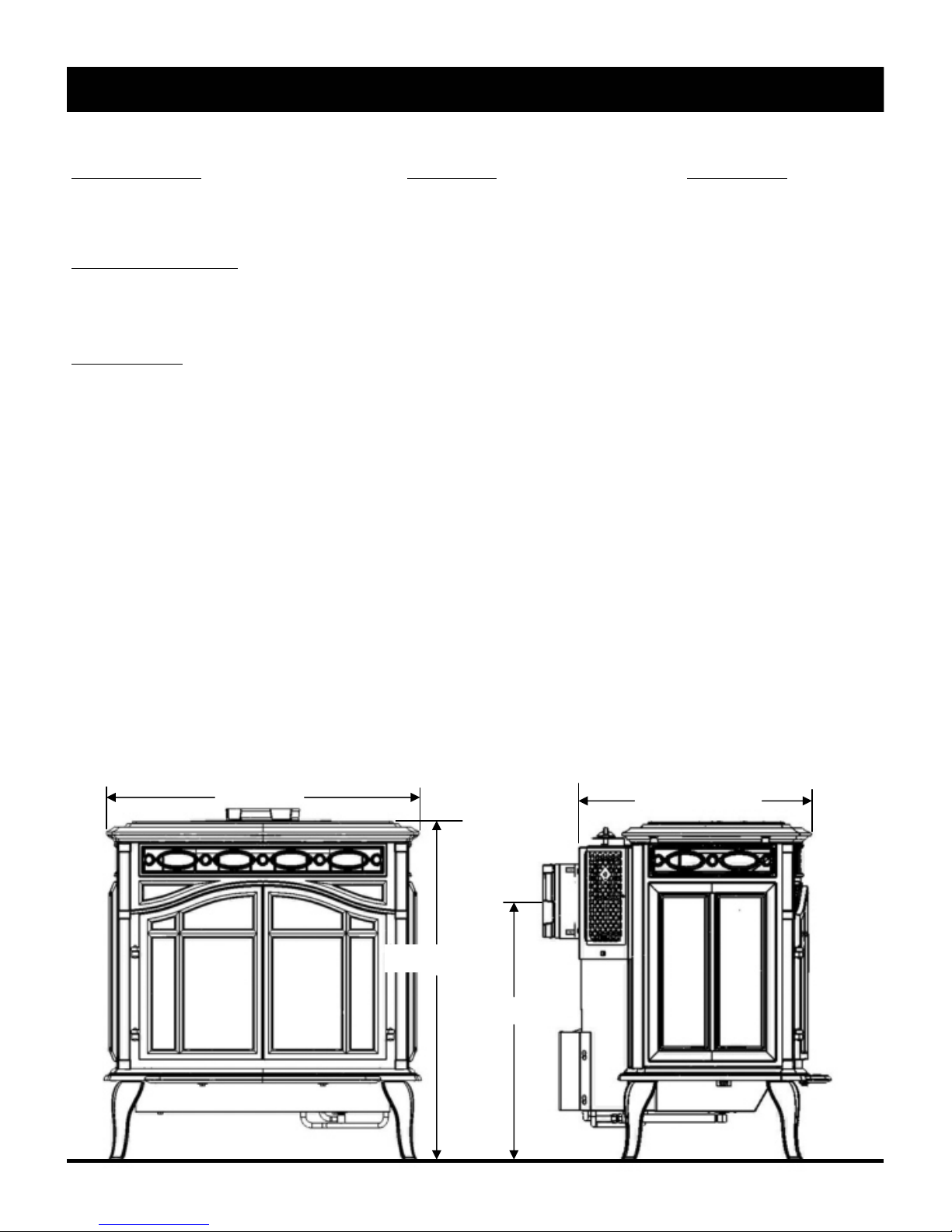
28” (71cm)
30 1/2” (77.5cm)
20 1/2”” (52cm)
23 1/4” (59cm)
5
INSTALLATION
Several issues must be addressed when selecting a suitable location for your FireLuxe. The minimum
clearances to combustible construction are listed below. In addition, access to the gas supply and electrical
supply must be considered. The location of the stove will also affect the venting requirements and you
must be certain the location will allow compliance with the venting requirements shown on pages 8 – 13.
You must also insure that your installation provides adequate accessibility clearance for servicing and
proper operation.
When the appliance is installed directly on carpeting or tile or other combustible material other than wood
flooring, the appliance shall be installed on a metal or wood panel extending the full width and depth of the
appliance.
Installation and repair should be done by a qualified service person. The appliance should be inspected
before use and at least annually by a professional service person. More frequent cleaning may be required
due to excessive lint from carpeting, bedding material, etc. It is imperative that the control compartments,
burners and circulating air passageways of the appliance be kept clean.
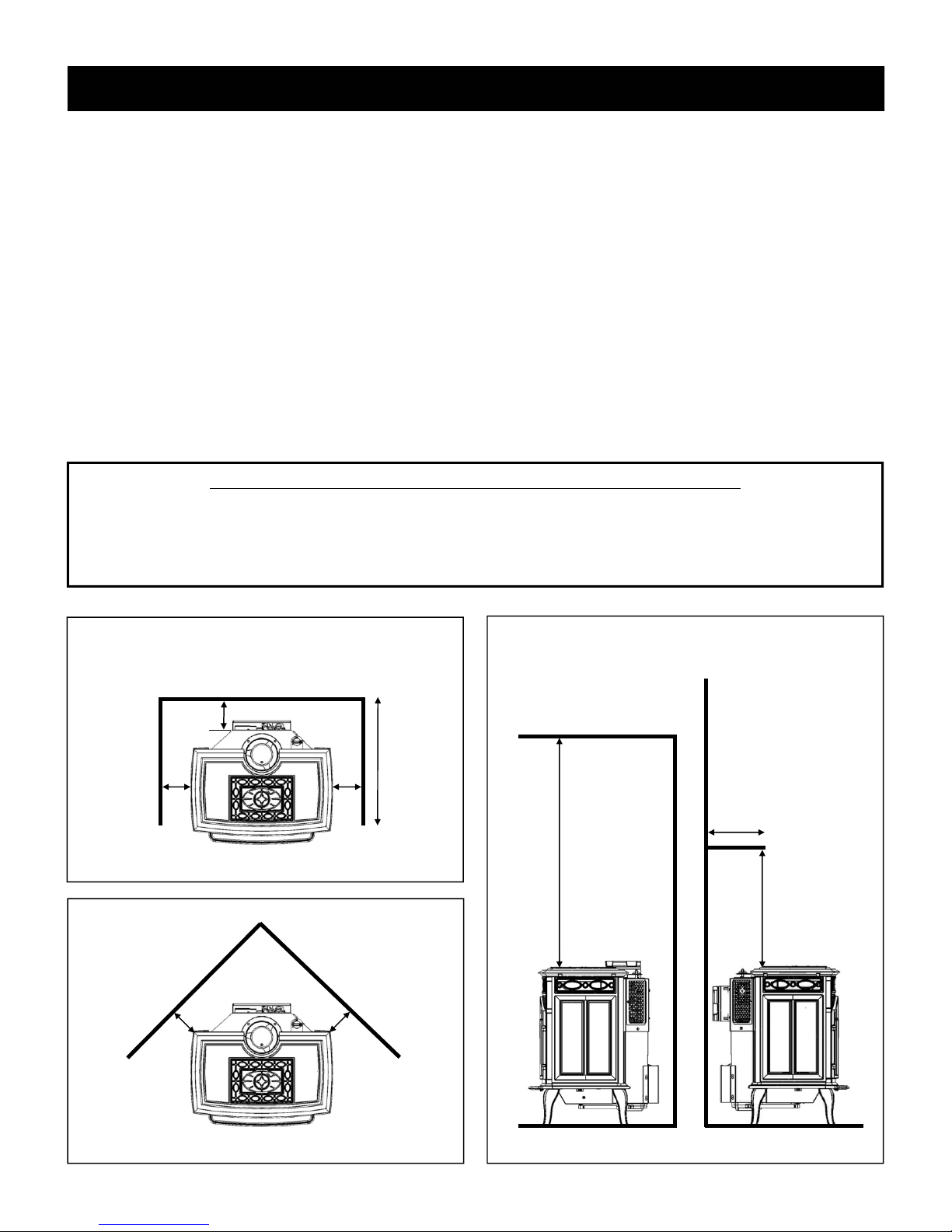
MINIMUM CLEARANCES TO COMBUSTIBLE CONSTRUCTION
Stove to Left Side Wall 6” (150mm) Stove to Corner Wall 6” (150mm)
Stove to Right Side Wall 6” (150mm) Stove to Ceiling 30” (760mm)
Stove to Rear Wall 6” (150mm) Stove to 10” Deep Mantel 30” (760mm)
Max. Alcove Depth 24” (610mm)
A = 6” (150mm)
B = 6” (150mm)
C = 6” (150mm)
D = 24” (610mm) Max. Alcove Depth
C
A
WALLS
E = 6” (150mm)
E
B
F = 30” (760mm)
G = 30” (760mm)
H = 10” (250mm) Max.
D
H
F
G
E
CORNER
CEILING MANTEL
6

INSTALLATION
NOTE: If you will be installing the optional warming shelves, make sure to plan for the additional width
that they occupy. For the details, see the information included with the warming shelf kit.
The gas stove is shipped with a flexible connector that has a 1/2” NPT female connection. The gas supply
piping should have a separate gas shutoff valve and a 1/8” NPT plugged tapping upstream of the valve. The
stove and its main control valve must be disconnected from the gas supply piping system during any pressure testing of that system at test pressures in excess of 1/2 psi (3.5 kPa). The stove must be isolated from
the gas supply piping system by closing the main control valve during any pressure testing of the gas supply
system at test pressures equal to or less than 1/2 psi (3.5 kPa). After the gas supply has been connected,
apply a soapy water solution to all the fittings to check for gas leaks. Never use a flame to test for leaks.
REQUIREMENTS FOR THE COMMONWEALTH OF MASSACHUSETTS
This product must be installed by a licensed plumber or gas fitter when installed within the Commonwealth of Massachusetts. If this appliance is installed in a dwelling, building or structure used in
whole or in part for residential purposes and the installation includes a horizontal vent termination
that is less than seven (7) feet above the finished grade in the area of the venting, including but not
limited to decks and porches, a hard-wired carbon monoxide detector with an alarm and battery
back-up must be installed on the floor level of the dwelling, building or structure where the appliance is to be installed.
Additionally, a hard-wired or battery operated carbon monoxide detector with an alarm must be installed on each additional level of the dwelling, building or structure served by the appliance. It shall
be the responsibility of the property owner to secure the services of qualified licensed professionals
for the installation of hard-wired carbon monoxide detectors.
In the event that the horizontally vented appliance is installed in a crawl space or attic, the hardwired carbon monoxide detector with alarm and battery back-up may be installed on the next adjacent floor level.
In the event that this requirement cannot be met at the time of completion of the installation of the
appliance, the owner shall have a period of thirty (30) days to comply with the requirement. However, during said thirty (30) day period, a battery operated carbon monoxide detector with alarm
must be installed.
Each carbon monoxide detector as required in accordance with the above provisions must comply
with NFPA 720 and be ANSI/UL 2034 and IAS certified.
In addition when the stove is horizontally vented and the vent termination is less than seven (7) feet
above finished grade a metal or plastic identification plate must be permanently mounted to the exterior of the building at a minimum height of eight (8) feet above grade directly in line with the exhaust vent terminal. The sign shall read, in print size no less than one-half (1/2) inch in size, “GAS
VENT DIRECTLY BELOW. KEEP CLEAR OF ALL OBSTRUCTIONS”.
A COPY OF THESE INSTRUCTIONS PLUS ALL VENTING INSTRUCTIONS WHICH INCLUDE PARTS LISTS, AND/OR ALL VENTING DESIGN INSTRUCTIONS MUST REMAIN
WITH THE STOVE AT THE COMPLETION OF THE INSTALLATION.
ATTENTION INSTALLERS: Mark below which venting system was used in the installation. These
instructions must remain with the FireLuxe Installation & Operation Manual.
Simpson DuraVent GS
To avoid confusion discard the all vent manufacturers instructions that do not apply to this installation.
AmeriVent Direct Security Secure Vent Selkirk DT
7
VENTING
The FireLuxe Gas Stove has been tested and listed for installation with 4” X 6 5/8” Simpson DuraVent GS,
AmeriVent Direct, Security Secure Vent and Selkirk DT direct venting components. For specific installation requirements, follow the installation instructions included by the venting manufacturer with the venting
system components you have chosen. The total vent length may not exceed 40 feet, including vertical rise
and horizontal run. The vent lengths are measured from the stove, not the floor. The minimum vertical rise
required is 2 feet. The maximum allowed horizontal vent run is 20 feet when the venting includes at least 5
feet of vertical rise. The maximum allowed horizontal vent run for vertical rises of less than 5 feet is shown
in the venting charts. No more than three elbows may be used in any installation. The venting charts include the use of one elbow. For the second or third elbows that are included in the installation, add 4 feet to
the actual horizontal run for each elbow to determine the equivalent horizontal run for the installation.
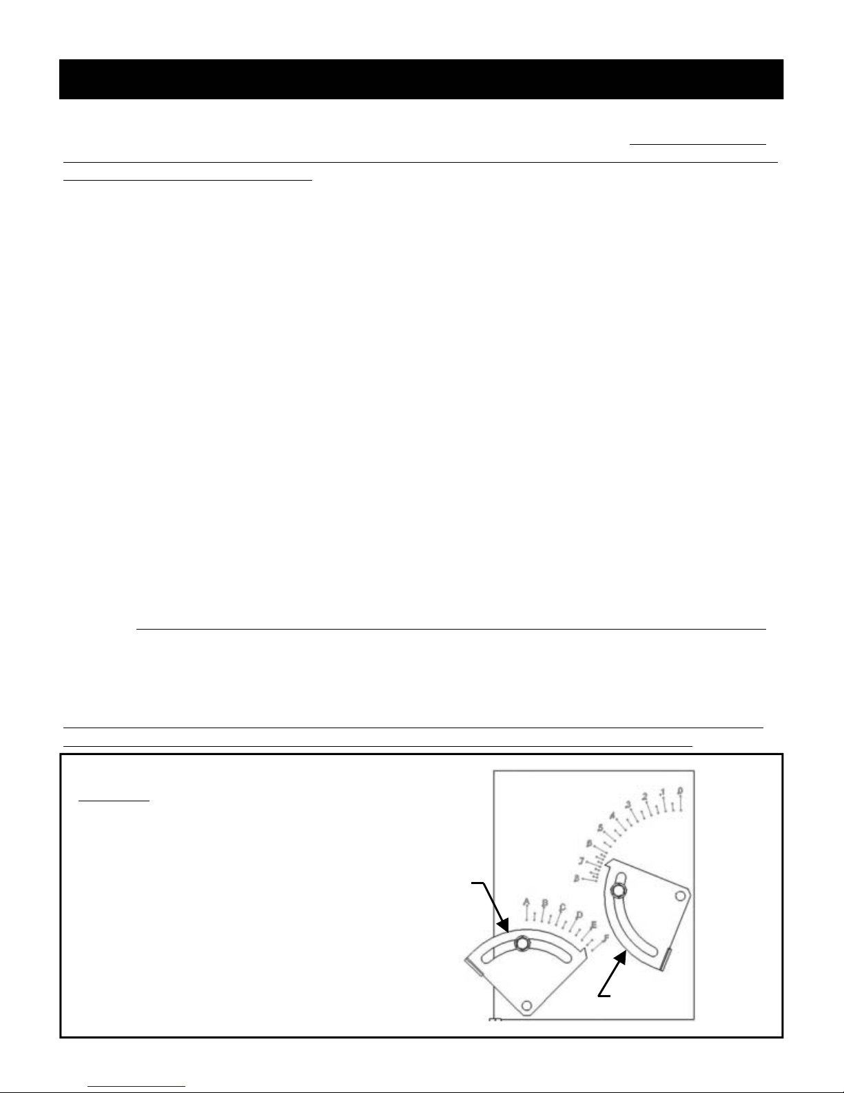
The venting charts allow a simple way to determine the recommended initial settings for both the air inlet
and exhaust restrictors. These settings have been determined by extensive testing and will be a good starting point while setting up the stove. Small adjustments from these settings may be needed to account for
specific installation variables. Please see the instructions on pages 21 - 22 for how to adjust the restrictors.
The letters (A-E) designate the position of the air inlet restrictor. When ½ is added to the letter designation,
this indicates that the position is halfway between adjacent letters. The numbers (0-8) indicate the position
of the exhaust restrictor. When ⅛, ¼, ⅜, ½, or ¾ is added to the number designation, this indicates that the
position is fractionally between adjacent numbers. For example, 5¼ is one-fourth the way between 5 and 6.
To use the charts, determine the horizontal run length and vertical rise length (in feet) for your installation.
If more than one elbow is used, add 4 feet to the actual horizontal run length for each additional elbow to
get the equivalent horizontal run for the chart. Note: Remember that a maximum of three elbows is allowed. Select the venting chart for the fuel type (Natural Gas or Propane (LP) Gas) and find the box on the
chart that corresponds to the vertical rise and actual horizontal run (or equivalent horizontal run, if two or
three elbows are used) and read the settings for the inlet air restrictor (A-E) and exhaust restrictor (0-8).
Examples are shown below and on page 9.
The FireLuxe is shipped with a Simpson DuraVent GS starter section that is specifically designed for the
FireLuxe. Regardless of the venting brand you chose, you must use the provided DuraVent starter section.
All of the venting brands listed for use with the FireLuxe are compatible with the provided starter section.
For venting system installation details, refer to the instructions provided with the venting system you have
chosen. Each brand has specific installation requirements that must be followed to insure a safe and functional venting system for your FireLuxe.
Note: The Fireluxe is shipped from the factory with restrictor settings for 2 feet of vertical rise and 1 foot
of horizontal run and for the fuel type listed on the rating plate attached to the rear of the stove.
Example 1
Fuel = Propane (LP)
Vertical Rise = 15 feet
Horizontal Run = 8 feet
Elbows = 1
Equivalent Horizontal Run = 8 feet
INLET AIR
6¾
Air Restrictor Setting = E½
Exhaust Restrictor Setting = 6¾
E½
EXHAUST
8
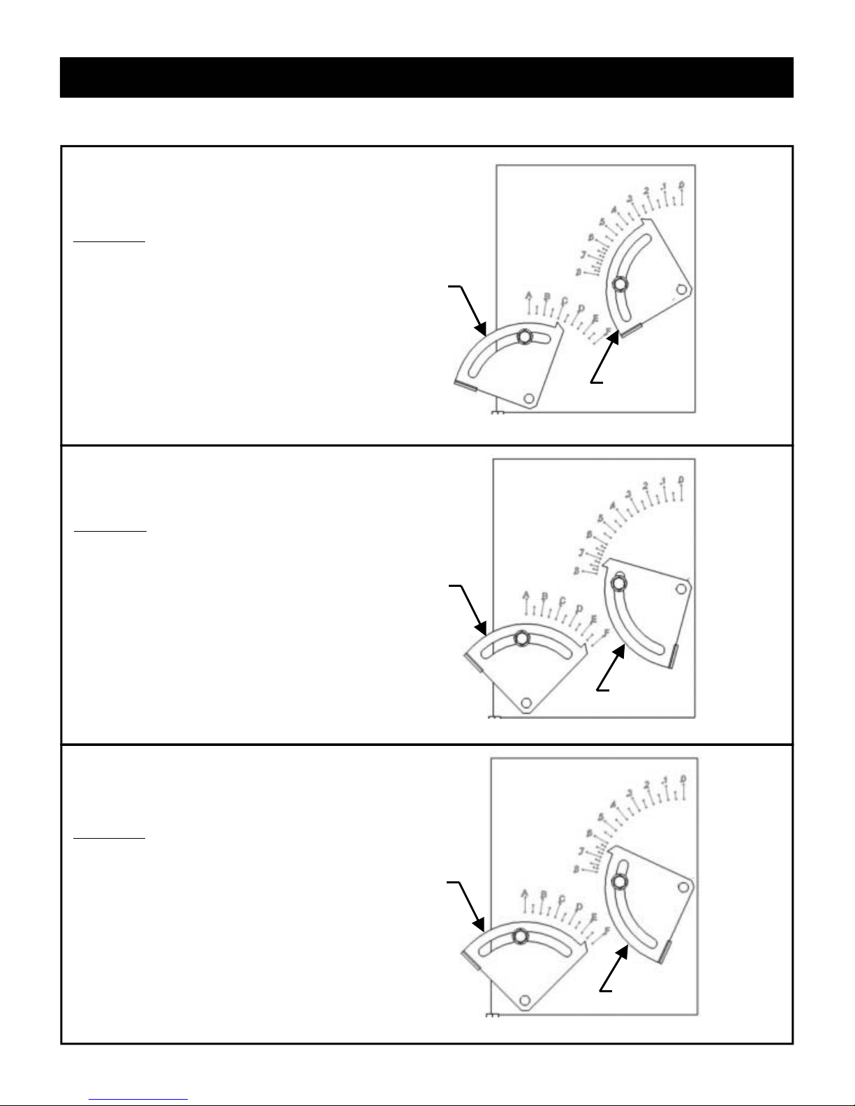
Example 2
Fuel = Propane (LP)
Vertical Rise = 6 feet
Horizontal Run = 8 feet
Elbows = 3
Equiv. Horizontal Run = 16 feet (8+4+4)
Air Restrictor Setting = C
Exhaust Restrictor Setting = 3
VENTING
INLET AIR
C
3
EXHAUST
Example 3
Fuel = Natural Gas
Vertical Rise = 22 feet
Horizontal Run = 0 feet
Elbows = 0
Equiv. Horizontal Run = 0 feet
Air Restrictor Setting = E ½
Exhaust Restrictor Setting = 7 ⅜
Example 4
Fuel = Propane (LP)
Vertical Rise = 12 feet
Horizontal Run = 4 feet
Elbows = 1
Equiv. Horizontal Run = 4
Air Restrictor Setting = E ½
Exhaust Restrictor Setting = 6 ½
INLET AIR
INLET AIR
7⅜
E½
EXHAUST
6½
E½
EXHAUST
9
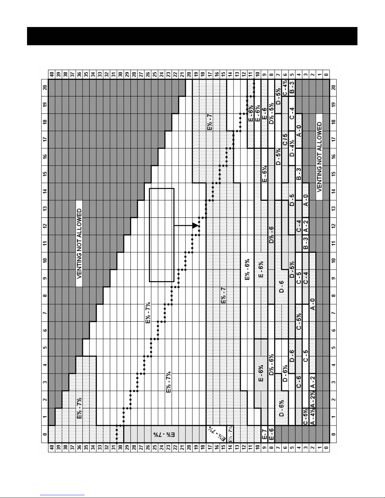
VENTING
NATURAL GAS VENTING
IF YOUR VENTING CONFIGURA-
TION FALLS ABOVE THIS DOT-
TED LINE, SEE PAGE 12
HORIZONTAL RUN IN FEET
VERTICAL RISE IN FEET
10
 Loading...