

Page 1
harman/kardon
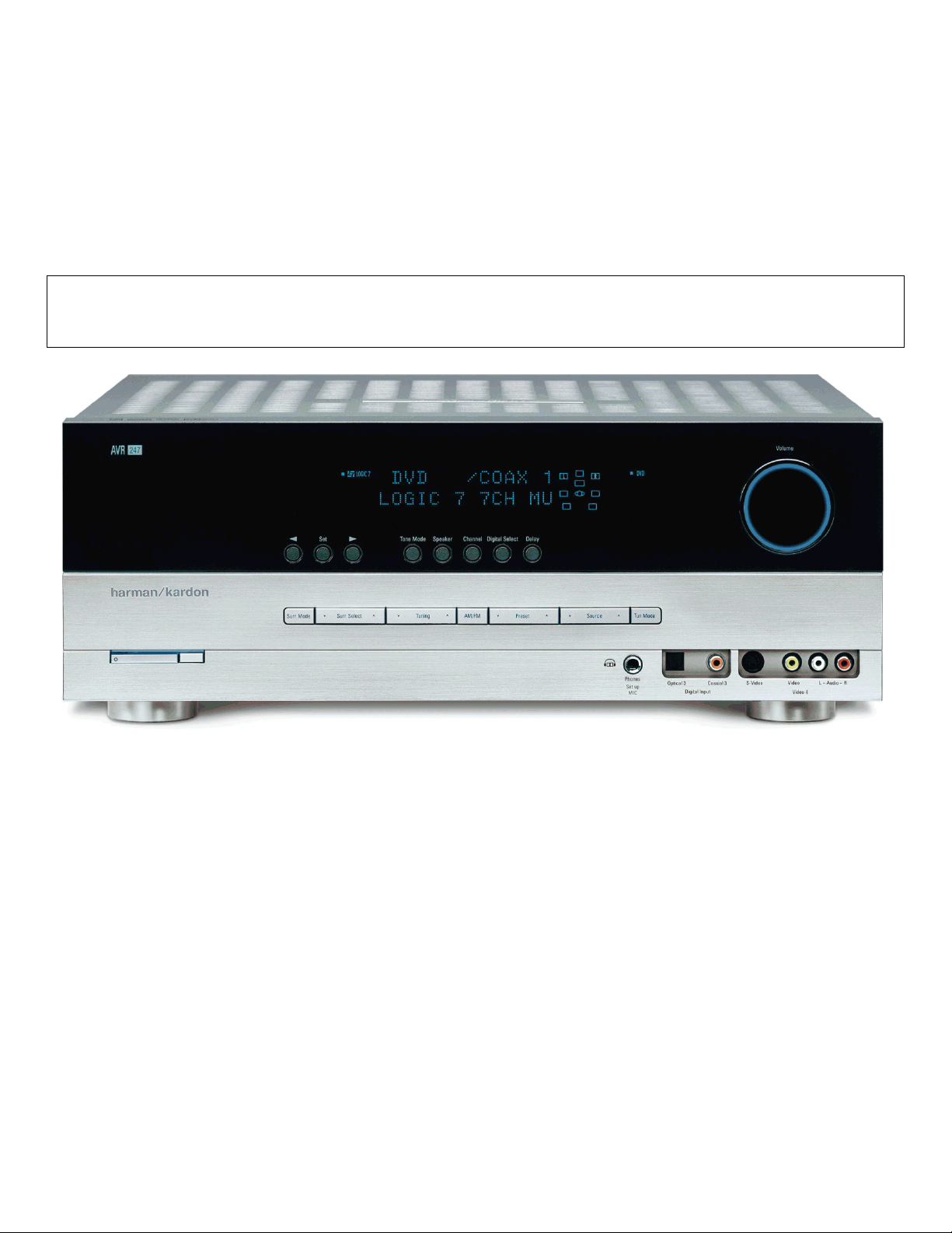
AVR247
7 X 50W 7.1 CHANNEL A/V RECEIVER
SERVICE MANUAL
CONTENTS
ESD WAR N ING……………………………….2
LEAKAGE TESTING……………….…..…....3
BASIC SPECIFICATIONS…………………..4
PACKAGING…………………………….……5
FRO NT PANEL CO NTRO L S ………..…..…..6
REAR PANEL CONNECTIONS………….…8
REMOTE CONTROL FUNCTIONS……….11
CONNECTIONS/INSTALLATION………....14
OPERATION………………………...………26
TROUBLESHOOTING GUIDE…...……..…34
REMOTE & PR OCESSOR R ESETS……....35
harman/kardon, Inc.
250 Crossways Park Dr.
Released 2007 Woodbur y, New York 11797 Rev0 6/2007
Discontinued XXXX
DISASSEM BLY…...…………………………..36
UNIT EXPLOD ED VIEW…………..…….…..41
EXPLODED VIEW PARTS LIST……………42
AMP BIAS ADJUSTMENT……………….…43
BLOCK DIAGRAM…………………………..44
PCB DRAWINGS……………………………45
ELECTRICAL PARTS LIST………..….……54
SEMICONDUCTOR PINOUTS…….………95
SCHEMATICS……………………………….196
WIRING DIAGRAM…………………………206
Page 2

AVR247 harman/kardon
2
Some semiconductor (solid state) devices can be damaged easily by static electricity. Such components commonly are called
Electrostatically Sensitive (ES) Devices. Examples of typical ES devices are integrated circuits and some field effect transistors and
semiconductor "chip" components.
The following techniques should be used to help reduce the incidence of component damage caused by static electricity.
1. Immediately before handling any semiconductor component or semiconductor-equipped assembly, drain off any electrostatic charge on
your body by touching a known earth ground. Alternatively, obtain and wear a commercially available discharging wrist strap device,
which should be removed for potential shock reasons prior to applying power to the unit under test.
2. After removing an electrical assembly equipped with ES devices, place the assembly on a conductive surface such as aluminum foil, to
prevent electrostatic charge build-up or exposure of the assembly.
3. Use only a grounded-tip soldering iron to solder or unsolder ES devices.
4. Use only an anti-static solder removal device. Some solder removal devices not classified as "anti-static" can generate electrical charges
sufficient to damage ES devices.
5. Do not use freon-propelled chemicals. These can generate electrical change sufficient to damage ES devices.
6. Do not remove a replacement ES device from its protective package until immediately before you are ready to install it. (Most replacement
ES devices are packaged with leads electrically shorted together by conductive foam, aluminum foil or comparable conductive material.)
7. Immediately before removing the protective material from the leads of a replacement ES device, touch the protective material to the
chassis or circuit assembly into which the device will be installed.
CAUTION :
8. Minimize bodily motions when handling unpackaged replacement ES devices. (Otherwise harmless motion such as the brushing together
or your clothes fabric or the lifting of your foot from a carpeted floor can generate static electricity sufficient to damage an ES devices.
Be sure no power is applied to the chassis or circuit, and observe all other safety precautions.
Each precaution in this manual should be followed during servicing.
Components identified with the IEC symbol in the parts list are special significance to safety. When replacing a component identified with
, use only the replacement parts designated, or parts with the same ratings or resistance, wattage, or voltage that are designated in the
parts list in this manual. Leakage-current or resistance measurements must be made to determine that exposed parts are acceptably
insulated from the supply circuit before retuming the product to the customer.
Page 3
SAFETY PRECAUTIONS
The following check should be performed for the continued
protection of the customer and service technician.
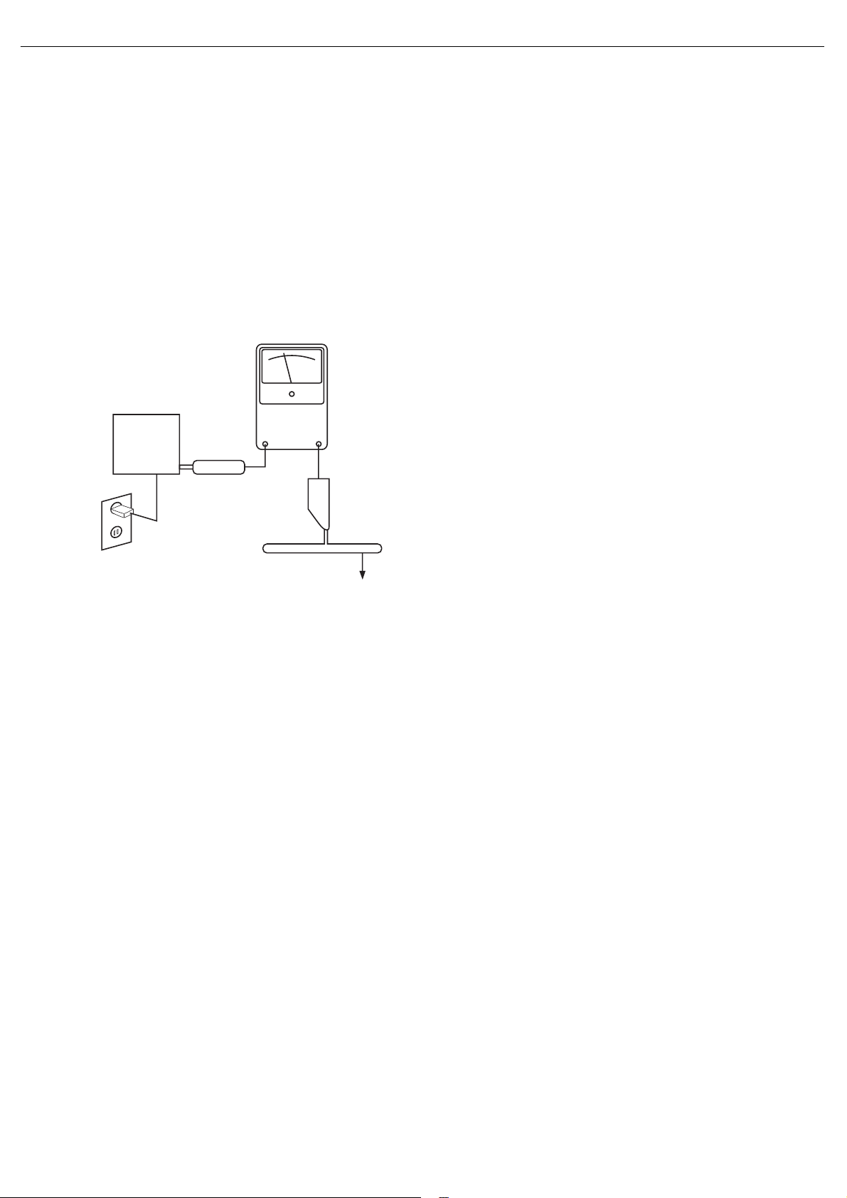
LEAKAGE CURRENT CHECK
Measure leakage current to a known earth ground (water
pipe, conduit, etc.) by connecting a leakage current tester
between the earth ground and all exposed metal parts of the
appliance (input/output terminals, screwheads, metal
overlays, control shaft, etc.). Plug the AC line cord of the
appliance directly into a 120V AC 60Hz outlet and turn the
AC power switch on. Any current measured must not exceed
o.5mA.
ANY MEASUREMENTS NOT WITHIN THE LIMITS
OUTLINED ABOVE ARE INDICATIVE OF A
POTENTIAL SHOCK HAZARD AND MUST BE
CORRECTED BEFORE RETURNING THE APPLIANCE
TO THE CUSTOMER.
3
AVR247 harman/kardon
Reading should
not be above
0.5mA
Device
under
test
Leakage
current
tester
Test all
exposed metal
surfaces
Also test with
plug reversed
(Using AC adapter
plug as required)
Earth
ground
AC Leakage Test
Page 4

The
Bridge
TM
4
AVR247 harman/kardon
AVR 247 TECHNICAL SPECIFICATIONS
Audio Section
Stereo Mode
Continuous Average Power (FTC)
65 Watts per channel, 20Hz–20kHz,
@ <0.07% THD, both channels driven into 8 ohms
Seven-Channel Surround Modes
Power per Individual Channel
Front L&R channels:
50 Watts per channel
@ <0.07% THD, 20Hz–20kHz into 8 ohms
Center channel:
50 Watts @ <0.07% THD, 20Hz–20kHz into 8 ohms
Surround (L & R Side, L & R Back) channels:
50 Watts per channel
@ <0.07% THD, 20Hz–20kHz into 8 ohms
Input Sensitivity/Impedance
Linear (High-Level) 200mV/47k ohms
Signal-to-Noise Ratio (IHF-A) 100dB
Surround System Adjacent Channel Separation
Pro Logic I/II 40dB
Dolby Digital (AC-3) 55dB
DTS 55dB
Frequency Response
@ 1W (+0dB, –3dB) 10Hz –130kHz
High Instantaneous
Current Capability (HCC) ±35 Amps
Transient Intermodulation
Distortion (TIM) Unmeasurable
Slew Rate 40V/µsec
FM Tuner Section
Frequency Range 87.5–108.0MHz
Usable Sensitivity IHF 1.3µV/13.2dBf
Signal-to-Noise Ratio Mono/Stereo 70/68dB
Distortion Mono/Stereo 0.2/0.3%
Stereo Separation 40dB @ 1kHz
Selectivity ±400kHz, 70dB
Image Rejection 80dB
IF Rejection 90dB
The AVR 247 is Simplay HD
™
-verified for compatibility
via the HDMI connection with other Simplay HD-verified products.
Please register your AVR 247 on our Web site at
www.harmankardon.com.
NOTE:
You’ll need the product’s serial number.
At the same time, you can choose to be notified about
our new products and/or special promotions.
AM Tuner Section
Frequency Range 520–1720kHz
Signal-to-Noise Ratio 45dB
Usable Sensitivity Loop 500µV
Distortion 1kHz, 50% Mod 0.8%
Selectivity ±10kHz, 30dB
Video Section
Television Format NTSC
Input Level/Impedance 1Vp-p/75 ohms
Output Level/Impedance 1Vp-p/75 ohms
Video Frequency Response
(Composite and S-Video) 10Hz–8MHz (–3dB)
Video Frequency Response
(Component Video) 10Hz–100MHz (–3dB)
™
HDMI
Audio and video processing
General
Power Requirement AC 120V/60Hz
Power Consumption 65W idle, 540W maximum
(7 channels driven)
Dimensions (Product) (Shipping)
Width 17-5/16 inches (440mm) 21-7/8 inches (555mm)
Height 6-1/2 inches (165mm) 10-1/2 inches (266mm)
Depth 15 inches (382mm) 18-5/16 inches (465mm)
(Product) (Shipping)
Weight 30.0 lb (13.6kg) 35.0 lb (15.9kg)
Depth measurement includes knobs, buttons and terminal connections.
Height measurement includes feet and chassis.
All features and specifications are subject to change without notice.
Harman Kardon and Logic 7 are trademarks of Harman International Industries, Incorporated, registered
in the United States and/or other countries. EzSet/EQ, and Designed to Entertain are trademarks
of Harman International Industries, Incorporated.
Apple, iTunes and iPod are trademarks of Apple Inc., registered in the U.S. and other countries.
Shuffle is a trademark of Apple Inc.
Audiovox is a registered trademark of Audiovox Corporation.
Blu-ray Disc is a trademark of the Blu-ray Disc Association.
CEA is a registered trademark of the Consumer Electronics Association.
Cirrus Logic is a registered trademark of Cirrus Logic, Inc.
Dolby, Pro Logic and the double-D symbol are trademarks of Dolby Laboratories.
Manufactured under license from Dolby Laboratories.
“DTS” and “DTS ESINeo:6” are registered trademarks of DTS, Inc. “96/24” is a trademark of DTS, Inc.
Faroudja and DCDi by Faroudja are registered trademarks of Genesis Microchip Inc.
HD-DVD is a trademark of the DVD Format/Logo Licensing Corporation (DVD FLLC).
HDMI is a trademark of HDMI Licensing LLC.
Microsoft and Xbox are registered trademarks of Microsoft Corporation in the United States and other countries.
SACD is a trademark of Sony Corporation.
The Simplay HD logo and the Simplay, Simplay HD and Simplay Labs trademarks are owned by
Silicon Image, Inc. and are used under license from Silicon Image, Inc. and/or Simplay Labs, LLC.
TiVo is a registered trademark of TiVo Inc.
XM and XM Ready are registered trademarks of XM Satellite Radio.
Page 5
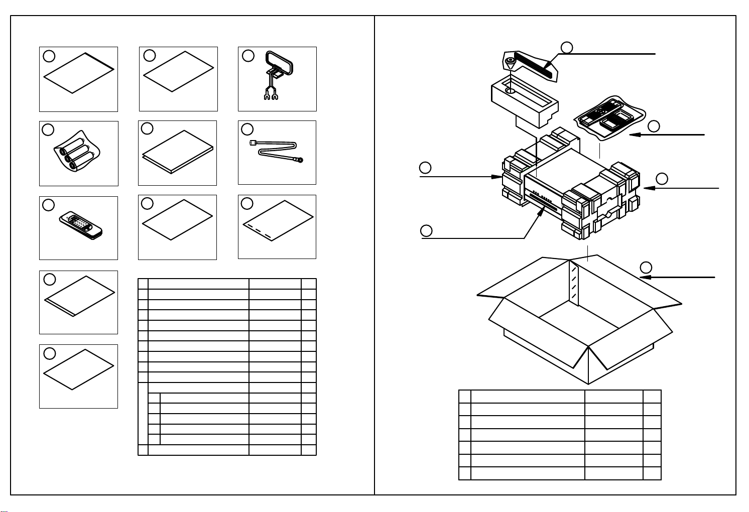
1. Instruction manual ass'y - Accessories 2. Package Drawing
5
1
2
3
MICROPHONE ASS'Y
6
AVR247
POLY BAG
4
BATTERY ASS'Y
7
REMOCON
TRANSMITTER ASS'Y
10
COVER ASS'Y
11
IMAGE BROCHURES
CARD WARRANTY
5
MANUAL INSTRUCTION
8
SHEET GUIDE
NO DESCRIPTION PARTS NO. Q,ty
1
CARD WARRANTY
2
3
AM LOOP ANTENNA ASS'Y
4
BATTERY
5
INSTRUCTION MANUAL
6
FM 1 POL ANT(UL)
7
REMOCON TRANSMITTER ASS'Y
SHEET GUIDE
8
STAPLE
9
COVER ASS'Y
10
COVER A
1
COVER B
2
SHEET, FRONT COVER
3
PAD,COVER
4
BAG,POLY
5
IMAGE BROCHURES11 HQE1A273Z 1
AM LOOP ANTENNA ASS'Y
6
FM 1 POLE ANT(UL)
9
STAPLE
CPB1061YPOLY BAG
CQE1A172X 1
CSA1A027Z
CABR03P3
CQX1A1184Z
CSA1A019Z 1
CARTAVR247
CQE1A330Z
CPL0905
CGRAVR130ZA
CGR1A331M7H43
CGR1A332M7H43
CQE1A219Z
CPS1A676
CPB1A176Z
MANUAL ASS'Y
1
2
SNOW PAD (L)
4
AVR247
1
1
3
1
1
1
1
3
1
1
1
11
1
1
1
2
4
5
DESCRIPTIONNO
MANUAL ASS'Y
SNOW,PAD(L)
CQXAVR247
CPS6A564
CPS6A565SNOW,PAD(R)3 1
AVR247 AVR247SET 1
BOX,OUT CARTON
CPG1A822X
SNOW PAD (R)
3
BOX ,OUT CARTON
5
Q,tyPARTS NO.
1
1
1
6 MICROPHONE ASS'Y CJXAVR340MICRO 1
Page 6

6
AVR247 harman/kardon
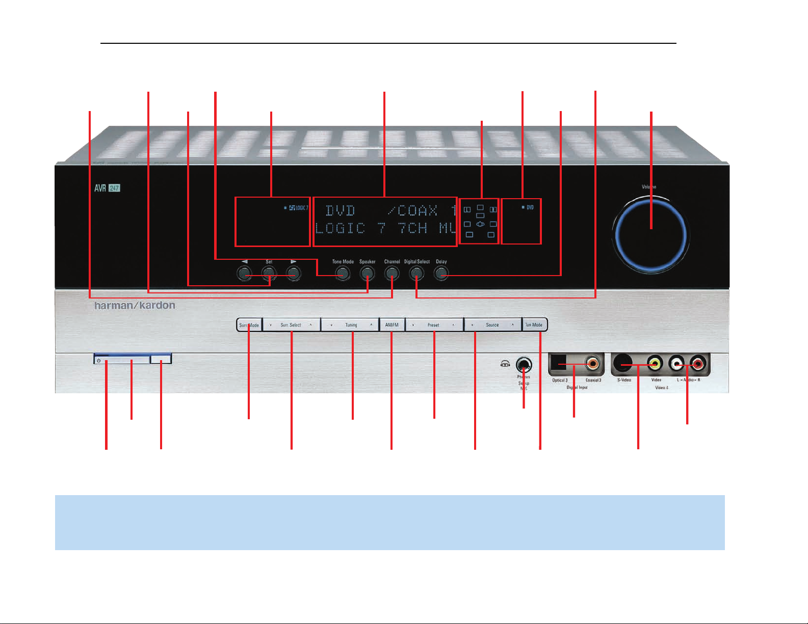
FRONT-PANEL CONTROLS
Main Power Switch: This mechanical switch turns the power supply
on or off. It is usually left pressed in (On position), and cannot be turned
on using the remote control.
Standby/On Switch: This electrical switch turns the receiver on
for playback, or leaves it in Standby mode for quick turn-on using this
switch or the remote control.
Power Indicator: This LED has three possible modes. When main
power is turned off, the LED is dark and the receiver won’t respond to
any button presses.When main power is turned on, but before the
Standby/On Switch is used, the LED turns amber to indicate that the
receiver is in Standby mode and ready to be turned on. When the
receiver is turned on, the LED turns blue.
Source Select: Press this button to select a source device, which
is a component where a playback signal originates, e.g., DVD, CD,
cable TV, satellite or HDTV tuner.
Source Indicators: The name of the current source input lights up.
The indicated input changes each time the Source Select button is
pressed.
Volume Knob: Turn this knob to raise or lower the volume, which will
be shown in decibels (dB) in the Message Display.
Message Display: Various messages appear in this two-line display
in response to commands and changes in the incoming signal. When
the on-screen display menu system (OSD) is in use, the message OSD
ON will appear to remind you to check the video display.
Tuner Band: Press this button to select the tuner as the source, to
switch between the AM and FM bands, or to select XM satellite radio.
Tuning: Press either side of this button to tune a radio station or XM
channel.
Tuning Mode: This button toggles between manual (one frequency
step at a time) and automatic (seeks frequencies with acceptable signal
strength) tuning mode. It also toggles between stereo and mono modes
when an FM station is tuned.
Surround Mode: Press this button to select a surround sound (e.g.,
multichannel) mode group. Choose from the Dolby modes, DTS modes,
Logic 7 modes, DSP modes or Stereo modes.
Surround Select: After you have selected the desired surround
mode group, press this button to select a specific mode.
Surround Mode Indicators: One or more of these icons may light
up as you select different surround modes.The Message Display also
indicates the surround mode.
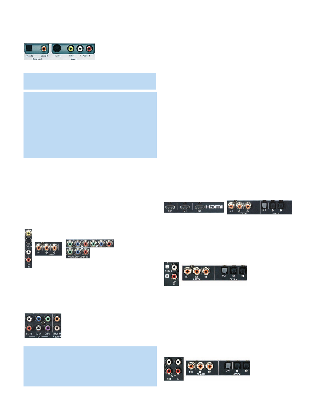
Analog Audio, Video and Digital Audio Inputs: Connect a
source component that will only be used temporarily, such as a camera
or game console, to these jacks. Use only one type of audio and one
type of video connection.
Speaker/Channel Input Indicators: The box icons indicate
which speaker positions you have configured, and the size (frequency
range) of each speaker. When a digital audio input is used, letters will
light inside the boxes to indicate which channels are present in the
incoming signal.
Navigation: These buttons are used together with the following five
buttons to make selections.
Tone Mode: Press this button to access the tone controls (bass and
‹/›
treble). Use the
Navigation Buttons to make your selections.
Speaker: Press this button to configure speaker sizes, that is, the
low-frequency-range capability of each speaker.
Channel Level Adjust: Press this button to set the output level for
each channel so that all speakers sound equally loud at the listening
position.
Digital Input Select: Press this button to select the specific digital
audio input (or analog audio input) you used for the current source.
Delay: Press this button to set delay times that compensate for plac-
ing the speakers at different distances from the listening position.
When XM Radio is in use, pressing this button repeatedly displays the
channel name, category, artist and track title in the lower line of the
Message Display. For traffic-and-weather channels, this button displays
the city, channel name, local weather and local temperature.
Preset Stations: Press this button to select a preset radio station.
Headphone Jack/EzSet/EQ Microphone Input: Plug a 1/4"
headphone plug into this jack for private listening.
This jack is also used to connect the supplied microphone before beginning the EzSet/EQ procedure described in the Initial Setup section. To
begin EzSet/EQ, plug the supplied microphone into this jack, place the
microphone at the listening position, and follow the directions given in
the Speaker Setup on-screen menu.
8
Page 7
Surround
Mode
Tuning
Preset Stations
Surround
Select
Tuner Band
Tuning
Mode
Source
Select
Headphone
Jack/EzSet/EQ
Microphone
Input
Digital
Audio Inputs
(Optical 3 and
Coaxial 3)
Video 4
Video Inputs
Video 4 Analog
Audio Inputs
Navigation
Tone Mode
Speaker Size
Setup
Delay
Digital Input
Select
Power
Indicator
Main Power
Switch
Standby/On
Switch
Volume
Source
Indicators
Message Display
Surround Mode Indicators
Speaker/Channel
Input Indicators
Channel Level
Adjust
7
AVR247 harman/kardon
NOTE: To make it easier to follow the instructions throughout the manual that refer to this illustration, a copy of this page may be downloaded from the Product Support section at
www.harmankardon.com.
Page 8

The
Bridge
TM
8
AVR247 harman/kardon
REAR-PANEL CONNECTIONS
AM and FM Antenna Terminals: Connect the included AM and
FM antennas to their respective terminals for radio reception.
XM Antenna Jack: Plug in an XM antenna module here. The XM
antenna module is purchased separately, and should specify that it is
for home use with an XM Ready
the XM service, which is available separately, and activate the service for
your antenna module. (XM service is not available in Alaska and Hawaii.)
®
product. You will need to subscribe to
Front, Center and Surround Speaker Outputs: Use two-
conductor speaker wire to connect each set of terminals to the correct
speaker. Remember to observe the correct polarity (positive and negative
connections). Always connect the positive lead to the colored terminal
on the receiver and the red terminal on the speaker. Connect the negative
lead to the black terminal on both the receiver and the speaker. See the
Connections section for more information on connecting your speakers.
Surround Back/Multiroom Speaker Outputs: These speaker
outputs may be used either for the surround back channels in a 7.lchannel home theater, or they may be reassigned to a remote room for
use with a multiroom system. When these outputs are reassigned for
multiroom operation, only a 5.1-channel configuration will be available in
the main listening room. Use the on-screen menu system to configure
these channels as desired.
As with the other speaker outputs, remember to observe proper polarity
by connecting the positive and negative output terminals to the corresponding terminals on each speaker.
Subwoofer Output: If you have a powered subwoofer with a line-
level input, connect it to this jack.
Preamp Outputs: Connect these jacks to an external amplifier if
more power is desired.
Surround Back/Multiroom Preamp Outputs: These outputs
may be used with an external amplifier either to power the surround
back channels, or to power the speakers in the remote zone of a multichannel system. Use the on-screen menu system to configure these
channels as desired.
Remote Infrared (IR) Input and Output: When the remote IR
receiver on the front panel is blocked, such as when the AVR is placed
inside a cabinet, connect an optional IR receiver to the Remote IR Input
jack for use with the remote control. The Remote IR Output may be
connected to the Remote IR Input of a compatible source device (or
other product) to enable remote control through the AVR. This is particularly useful in multiroom applications, when you wish to control the
source device from the remote room (when used with the Multiroom IR
Input). When several source devices are used, connect them in “daisy
chain” fashion.
Multiroom Infrared (IR) Input: Connect a remote IR receiver
located in the remote zone of a multiroom system to this jack to control
the AVR and any source devices connected to the Remote IR Output
from the remote zone.
Video 1, Video 2, Video 3 and DVD Audio/Video Inputs:
These jacks may be used to connect your video-capable source
components (e.g., VCR, DVD player, cable TV box) to the receiver.
Remember to use only one type of video connection for each source.
See the Connections section for more information on audio and video
connection options for each source component.
Video 1 Audio/Video Outputs: These jacks may be used to
connect your VCR or another recorder.
Composite and S-Video Monitor Outputs: If any of your
sources use composite or S-video connections, you may need to
connect one or both of these monitor outputs to the corresponding
inputs on your television or video display in order to view the sources
and to view the on-screen displays. If your video display is equipped
with HDMI or component video inputs, you may take advantage of the
AVR 247’s transcoding capability, which transcodes composite and
S-video signals to HDMI and component video, allowing for only a
single video connection from the AVR to the video display.
HDMI Inputs and Output: HDMI (High-Definition Multimedia
Interface) is a newer type of connection for transmitting digital audio and
video signals between devices.With the AVR 247’s powerful processor,
you may connect up to two HDMI-equipped source devices to the HDMI
inputs using a single-cable connection, while benefiting from superior
digital audio and video performance. However, if your video display is
not HDMI-compatible, you will need to connect the device to one of the
other source inputs, selecting a coaxial or optical digital audio input and
analog video input. See the Connections and Installation sections for
more information.
If your video display has an HDMI input, but some of your sources
have only analog video outputs, you may still rely on just the HDMI video
connection to your display; the AVR 247 will automatically transcode
analog video signals up to 720p to the HDMI format. High-resolution
analog 1080i or higher signals are not available at the HDMI Output.
The AVR 247 is Simplay HD-verified for compatibility via the HDMI
connection with other Simplay HD-verified products.
CD and Tape Audio Inputs: These jacks may be used to connect
audio-only source components (e.g., CD player, tape deck). Do not
connect a turntable to these jacks without a phono preamp.
Tape Outputs: These jacks may be used to connect a CDR or
another audio-only recorder.
Coaxial and Optical Digital Audio Inputs: If a source has
a compatible digital audio output, connect it to one of these jacks
for improved audio performance. Use only one type of digital audio
connection for each source.
Coaxial and Optical Digital Audio Outputs: If a source is
also an audio recorder, you may connect a compatible digital audio
output to the recorder’s input for improved recording quality.
The Bridge/DMP Input: Connect the optional Harman Kardon
to this input for use with your iPod (not included). Make
sure the receiver is turned off (in Standby mode) when connecting
The Bridge.
Page 9

9
AVR247 harman/kardon
REAR-PANEL CONNECTIONS
6-/8-Channel Inputs: Connect the multichannel analog audio
™
outputs of a DVD-Audio, SACD
(or any other external decoder) to these jacks to enjoy these proprietary
formats.
NOTE: When an HD-DVD or Blu-ray Disc player has an
onboard digital decoder, it is not necessary to connect it to
the 6-/8-Channel Analog Audio Inputs. Only a digital audio
connection (HDMI, coaxial or optical) is needed.
, Blu-ray Disc™or HD-DVD™player
Component Video Inputs: If both a video source (e.g., DVD
player or HDTV tuner) and your television or video display have analog
component video (Y/Pb/Pr) capability, and if you are not using an HDMI
connection for the device, then you may connect the component video
outputs of the source to one of the two component video inputs. Do
not make any other video connections to that source.
Component Video Monitor Outputs: If you are using one of
the Component Video Inputs and your television or video display is
component-video-capable, and if you are not connecting the HDMI
Output to your display, you may connect these jacks to the corresponding inputs on your video display.
NOTES:
• Due to copy-protection restrictions, there is no output at
the Component Video Monitor Outputs for copy-protected
sources.
• High-resolution 1080i and 1080p video signals are not
available at the HDMI Output, and are downconverted to
720p for the Component Video Outputs. If your source outputs
analog high-resolution video, either use the Component Video
Outputs, lower the output resolution of your source device, or
connect your source’s component video outputs directly to
your video display.
• Due to the design of some video displays, analog 480p or
720p component video source signals may produce artifacts
when used with the AVR’s analog video outputs (composite,
S-video or component video). If this occurs, try changing the
Video Mode setting in the INPUT SETUP menu, or connecting
the source device’s video output directly to your video display.
However, for best results, we recommend you consider
upgrading to an HDMI-capable video display.
Switched AC Accessory Outlet: You may plug the AC power
cord of one source device into this outlet, and it will turn on whenever
you turn on the receiver. Do not use a source that consumes more than
50 watts of power.
AC Power Cord: After you have made all other connections, plug
the AC power cord into an unswitched outlet.
RS-232 Serial Port: This specialized connector may be used with
your personal computer in case Harman Kardon offers a software
upgrade for the receiver at some time in the future.
RS-232 Mode: Leave this switch popped out in the Operate position
unless the AVR 247 is being upgraded.
RS-232 Reset: This switch is only used during a software upgrade.
A standard processor reset is performed by pressing and holding the
front-panel Tone button.
Page 10
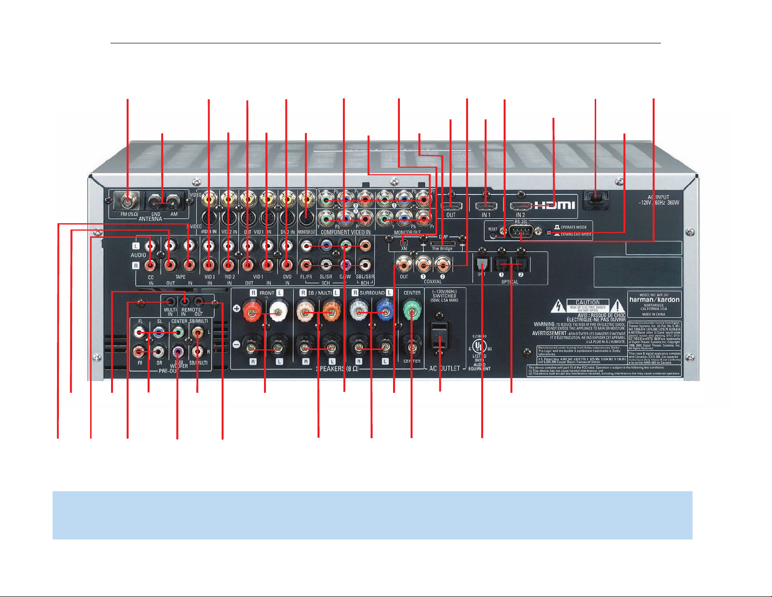
FM Antenna
XM
Antenna
Jack
AM Antenna
Video 2
A/V
Inputs
Video 1
A/V
Outputs
Video 3
A/V
Inputs
Video 1
A/V
Inputs
Video
Monitor
Outputs
DVD A/V
Inputs
Component
Video
Inputs
(1, 2 & 3)
Component
Video
Monitor
Outputs
AC Power
Cord
RS-232
Serial Port
Coaxial Digital
Audio
Inputs
(1 & 2)
RS-232
Mode
The
Bridge/
DMP
Input
RS-232
Reset
HDMI
Output
HDMI 2
Input
HDMI1
Input
Subwoofer
Output
Preamp
Outputs
Front Speaker
Outputs
Surround
Speaker
Outputs
6-/8Channel
Inputs
Surround
Back/Multiroom
Speaker Outputs
Surround
Back/
Multiroom
Preamp
Outputs
Center Speaker
Outputs
Switched AC
Accessory
Outlet
Coaxial
Digital
Audio
Output
Optical Digital
Audio Inputs (1 & 2)
Optical Digital
Audio Output
CD
Inputs
Multiroom
IR Input
Remote
IR Input
Remote
IR Output
Tape
Outputs
Tape
Inputs
10
AVR247 harman/kardon
NOTE: To make it easier to follow the instructions throughout the manual that refer to this illustration, a copy of this page may be downloaded from the Product Support section at
www.harmankardon.com.
Page 11

11
AVR247 harman/kardon
REMOTE CONTROL FUNCTIONS
The AVR 247 remote is capable of controlling 11devices, including the
AVR itself and an iPod docked in the optional The Bridge accessory.
During the installation process, you may program the codes for each
of your source components into the remote. Each time you wish to use
the codes for any component, first press the Selector button for that
component. This changes the button functions to the appropriate codes
for that product.
NOTE: Several of the Input Selectors are shared between two
devices.The selector button will light in red when the remote
is in the device mode printed on the button, and it will light in
green for the device mode printed above the button. To switch
between the two device modes, press the selector
in succession. The selector will remain in the last-selected mode
until the next time you press the selector twice quickly.
For example, the first time you press the DVD button, the button
will light up in red, indicating that the remote is in DVD mode. If
you press another selector, such as the VID3 selector, and then
press the DVD button again, the DVD button will remain red,
indicating the remote is still in DVD mode. Now press the DVD
button twice quickly. At the first press the button will light red,
indicating that the remote is in DVD mode. On the second press
the button will turn green, indicating that the remote is now in CD
mode. If you press a different selector and return to the DVD/CD
Selector, you will observe that the remote is still in CD mode.
Each Input Selector has been preprogrammed to control certain types
of components, with only the codes specific to each brand and model
changing, depending on which product code is programmed.The
device types programmed into each selector may not be changed.
However, you may program the HDMI 1 and 2 Selectors with the DVD,
cable/satellite or VCR/PVR device type.
twice quickly
DVD: Controls DVD players and recorders.
CD: Controls CD players and recorders.
Tape: Controls cassette decks.
Video 1: Controls VCRs, TiVo
®
and PVRs.
Video 2: Controls cable and satellite television set-top boxes.
Video 3: Controls televisions and other video displays.
Video 4: Controls televisions and other video displays.
HDMI 1 and 2: Each code set controls a source device (VCR/PVR,
DVD player or cable/satellite set-top box) connected to one of these
two inputs.
XM: Controls the AVR functions for XM Satellite Radio.
The Bridge/DMP: Controls an iPod docked in The Bridge.
For example, if you have inserted a disc in your CD player and you
would like to skip ahead three tracks, but you then find that the volume
is too loud, you would follow this procedure:
1. Press the CD Input Selector to switch to the codes that control your
CD player. If the remote is in DVD mode, press the selector twice quickly
to switch to CD mode, indicated by the selector lighting in green.
2. Press the Play Button (in the Transport Controls section) if the disc
is not already playing.
3. Press the Skip Up Button three times to advance three tracks.
4. Press the AVR Button so that you can access the Volume Controls.
5. Press the Volume Down Button until the volume level is satisfactory.
Any given button may have different functions, depending on which
component is being controlled. Some buttons are labeled with these
functions. For example, the Sleep and DSP Surround Buttons are
labeled for use as Channel Up/Down Buttons when controlling a television or cable box. See Table A8 in the appendix for listings of the
different functions for each type of component.
IR Transmitter Lens: As buttons are pressed on the remote,
infrared codes are emitted through this lens. Make sure it is pointing
toward the component being operated.
Power On Button: Press this button to turn on the AVR or another
device.The Master Power Switch on the AVR 247’s front panel must
first have been switched on.
Mute Button: Press this button to mute the AVR 247’s speaker and
headphone outputs temporarily. To end the muting, press this button
or adjust the volume. Muting is also canceled when the receiver is
turned off.
Program Indicator: This LED lights up or flashes in one of three colors
as the remote is programmed with codes.
Power Off Button: Press this button to turn off the AVR 247 or
another device.
AVR Selector: Press this button to switch the remote to the codes
that operate the receiver.
Input Selectors: Press one of these buttons to select a source
device, which is a component where a playback signal originates, e.g.,
DVD, CD, cable TV, satellite or HDTV tuner, or an iPod docked in the
optional The Bridge. This will also turn on the receiver and switch the
remote’s mode to operate the source device.
XM Radio Button: Press this button to select XM Satellite Radio as
the source.You will need to have purchased and activated an XM antenna
module, and you will also need to subscribe to the XM Radio service.
Visit www.xmradio.com for more information.
AM/FM Button: Press this button to select the tuner as the source,
or to switch between the AM and FM bands, or XM Radio.
6-/8-Channel Input Selector: Press this button to select the
6-/8-Channel Inputs as the audio source.The receiver will use the video
input and remote control codes for the last-selected video source.
Test Tone: Press this button to activate the test tone for manual
output-level calibration.
TV/Video: This button has no effect on the receiver, but is used to
switch video inputs on some video source components.
Page 12
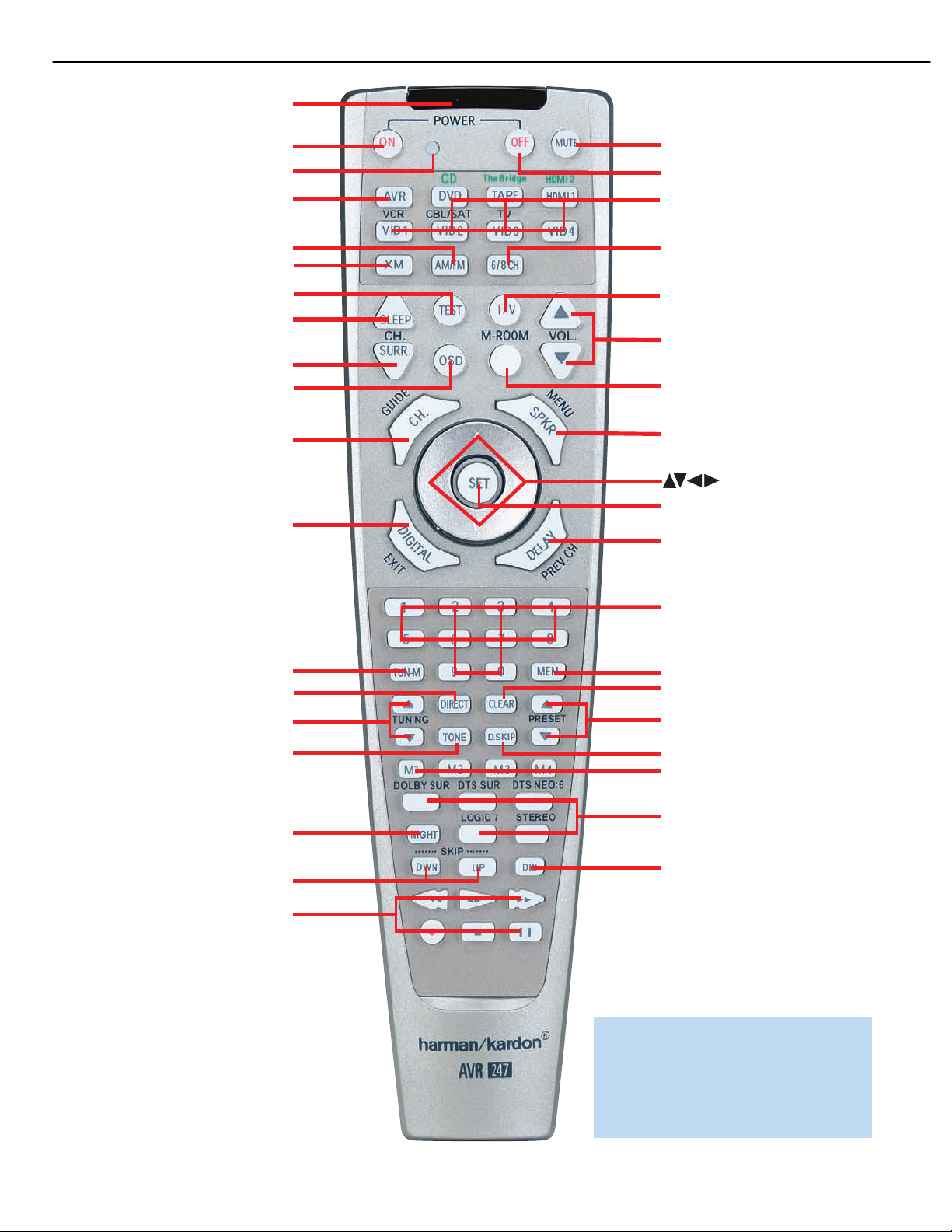
IR Transmitter Lens
Program Indicator
Power On
AVR Selector
AM/FM
XM Radio
Test Tone
Sleep
DSP Surround
On-Screen Display
Channel Level
Digital Input
Tuning Mode
Direct Station Entry
Tuning
Tone Mode
Night Mode
Track Skip
Transport Controls
Power Off
Mute
Input Selectors
6-/8-Channel Input Selector
TV/Video
Volume Controls
Multiroom
Speaker Setup
Set
Navigation
Numeric Keys
Delay
Memory
Clear
Preset Stations Selectors
Disc Skip
Macros
Surround Mode Selectors
Dim
12
AVR247 harman/kardon
NOTE: To make it easier to follow the instructions throughout the manual that refer to this
illustration, a copy of this page may be downloaded from the Product Support section at
www.harmankardon.com.
14
Page 13

13
AVR247 harman/kardon
REMOTE CONTROL FUNCTIONS
Sleep Button: Press this button to activate the sleep timer, which turns
off the receiver after a programmed period of time of up to 90 minutes.
Volume Controls: Press these buttons to raise or lower the volume,
which will be shown in decibels (dB) in the Message Display.
DSP Surround: Press this button to select a DSP surround mode
(Hall 1, Hall 2, Theater).
On-Screen Display (OSD): Press this button to activate the
on-screen menu system.
Multiroom: Press this button to control the multiroom system. Three
settings are available: MULTI ON/OFF, which is used to turn the multiroom
system on or off; MULTI LEVEL, which adjusts the volume of the remote
zone only; and MULTI INPUT, which is used to select the source input for
the remote zone. See Multiroom Operation in the Advanced Functions
section for more information on using the AVR 247’s multiroom system.
Channel Level: Press this button to adjust the output levels for each
channel so that all speakers sound equally loud at the listening position.
Usually this is done while playing an audio selection, such as a favorite CD,
after you have calibrated the levels using EzSet/EQ, as described in the Initial
Setup section.
Speaker Setup: Press this button to configure speaker sizes, that is,
the low-frequency capability of each speaker. Usually this is done using
the on-screen menu system, as described in the Initial Setup section.
Navigation (
used to make selections within the on-screen menu system, or when
accessing the functions of the four buttons surrounding this area of the
remote – Channel Level, Speaker Setup, Digital Input or Delay.
⁄/¤
›
/‹/
) and Set Buttons: These buttons are
Digital Input Select: Press this button to select the specific digital
audio input (or analog audio input) you used for the current source.
Delay: Press this button to set delay times that compensate for placing
the speakers at different distances from the listening position, or to
resolve a “lip sync” issue that may be caused by digital video processing.
This may also be done using the on-screen menu system, as described
in the Initial Setup section.
Numeric Keys: Use these buttons to enter radio station frequencies
or to select station presets.When the AM or FM band is in use, press
the Direct Button before entering the station frequency.
When listening to XM Radio, you may enter channel numbers without first
pressing the Direct Button; however, to access the preset stations, you will
need to use the Preset Stations Selectors.To access another bank of XM
presets, press the Set Button repeatedly until PRESET SEARCH appears,
then use the
⁄/¤
Buttons to select the letter of the desired bank.
Tuning Mode: When listening to AM or FM radio, this button toggles
between manual (one frequency step at a time) and automatic (seeks
frequencies with acceptable signal strength) tuning mode. It also toggles
between stereo and mono modes when an FM station is tuned.
When listening to XM Radio, press the Tuning Mode Button once to view
the category name of the current channel. Additional presses will display
the artist, song title and channel name.
Memory: After you have tuned a particular radio station, press this
button, then the numeric keys, to save that station as a radio preset.
For XM Radio, the procedure for saving a preset is a little different. To
save the current channel in one of the 40 available preset locations,
press the Set Button repeatedly until PRESET SEARCH appears. Use
⁄/¤
the
the five banks of preset memory slots. Then press the Memory Button,
followed by a Numeric Key (1 through 8) for the precise preset memory
location you wish to save the channel in.
Buttons to select a letter (A through E) representing one of
Tuning: Press these buttons to tune a radio station or XM Radio
channel. For the AM and FM bands, and depending on whether the
tuning mode has been set to manual or automatic, each press will either
change one frequency step at a time, or seek the next frequency with
acceptable signal strength.
Direct: Press this button before using the Numeric Keys to directly
enter a radio station frequency (AM or FM bands only).
Clear: Press this button to clear a radio station frequency you have
started to enter.
Preset Stations Selector: Press these buttons to select a preset
radio station.
For XM Radio, first press the Set Button repeatedly until PRESET SEARCH
⁄/¤
appears and then use the
desired bank of presets.
Buttons to select the letter of the
Tone Mode: Press this button to access the tone controls (bass and
treble). Use the Navigation Buttons to make your selections.
Disc Skip: This button has no effect on the receiver, but is used with
some optical disc changers to skip to the next disc.
Macros: These buttons may be programmed to execute long command
sequences with a single button press.They are useful for programming the
command to turn on or off all of your components, or for accessing specialized functions for a different component than you are currently operating.
Surround Mode Selectors: Press any of these buttons to select
a type of surround sound (e.g., multichannel) mode. Choose from the
Dolby modes, DTS modes, Logic 7 modes or Stereo modes. Each
press of a button will cycle to the next available variant of that mode.
Not all modes or mode groups are available with all sources.
Night Mode: Press this button to activate Night mode with specially
encoded Dolby Digital discs or broadcasts. Night mode compresses the
audio so that louder passages are reduced in volume to avoid disturbing
others, while dialogue remains intelligible.
Track Skip: These buttons have no effect on the receiver, but are
used with many source components to change tracks or chapters.
Dim: Press this button to partially or fully dim the front-panel display.
Transport Controls: These buttons have no effect on the receiver,
but are used to control many source components. By default, when the
remote is operating the receiver, these buttons will control a DVD player.
Page 14
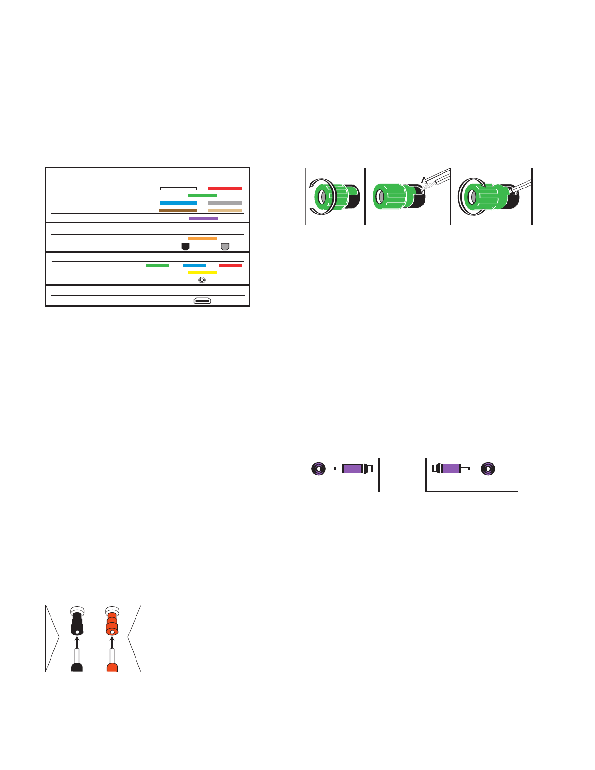
SubwooferPreout
HOW TO USE THE BINDING-POST SPEAKER TERMINAL
COMMENT UTILISER LA BORNE DES HAUT-PARLEURS DE CONNEXION
CÓMO USAR EL TERMINAL DE ALTAVOZ DE POSTE DE SUJECIÓN
Audio Connections
Left Right
Front (FL/FR)
Center (C)
Surround (SL/SR)
Subwoofer (SUB)
Digital Audio Connections
Coaxial
Optical Output Input
Video Connections
C
omponent Y Pb Pr
Composite
S-Video
12 3
+
Audio Connections
Left Right
Front (FL/FR)
Center (C)
Surround (SL/SR)
Surround Back (SBL/SBR)
Subwoofer (SUB)
Digital Audio Connections
C
oaxial
Optical Input Output
V
ideo Connections
Component Y Pb Pr
Composite
S-Video
HDMI™ Connections (digital audio/video)
HDMI
14
AVR247 harman/kardon
CONNECTIONS
There are different types of audio and video connections used to
connect the receiver to the speakers and video display, and to connect
the source devices to the receiver. To make it easier to keep them all
straight, the Consumer Electronics Association (CEA
a color-coding standard. Table 1 may be helpful to you as a reference
while you set up your system.
Table 1 – Connection Color Guide
Types of Connections
This section will briefly review different types of cables and connections
that you may use to set up your system.
Speaker Connections
Speaker cables carry an amplified signal from the receiver’s speaker
terminals to each loudspeaker. Speaker cables contain two wire conductors, or leads, inside plastic insulation. The two conductors are usually
differentiated in some way, by using different colors, or stripes, or even
by adding a ridge to the insulation. Sometimes the actual wires are
different, one being copper-colored and the other silver.
The differentiation is important because each speaker must be connected
to the receiver’s speaker-output terminals using two wires, one positive
(+) and one negative (–), referred to as speaker polarity. It’s important
to maintain the proper polarity for all speakers in the system. If some
speakers have their negative terminals connected to the receiver’s positive
terminals, performance can suffer, especially for the low frequencies.
Always connect the positive terminal on the loudspeaker, which is usually
colored red, to the positive terminal on the receiver, which is colored as
shown in the Connection Color Guide (Table 1). Similarly, always connect
the black negative terminal on the speaker to the black negative terminal
on the receiver.
The AVR 247 uses binding-post speaker
terminals that can accept banana plugs
or bare-wire cables. Banana plugs are
simply plugged into the hole in the middle
of the terminal cap. See Figure 1.
Figure 1 – Binding-Post Speaker Terminals With Banana Plugs
17
®
) has established
Bare wire cables are installed as follows (see Figure 2):
1. Unscrew the terminal cap until the pass-through hole in the collar is
revealed.
2. Insert the bare end of the wire into the hole.
3. Hand-tighten the cap until the wire is held snugly.
Figure 2 – Binding-Post Speaker Terminals With Bare Wires
Subwoofer
The subwoofer is a specialized type of loudspeaker that is usually
connected in a different way. The subwoofer is used to play only the
low frequencies (bass), which require much more power than the other
speaker channels. In order to obtain the best results, most speaker
manufacturers offer powered subwoofers, in which the speaker contains
its own amplifier on board. Sometimes the subwoofer is connected to
the receiver using the front left and right speaker outputs, and then the
front left and right speakers are connected to terminals on the subwoofer.
More often, a line-level (nonamplified) connection is made from the
receiver’s Subwoofer Output to a corresponding jack on the subwoofer,
as shown in Figure 3.
Although the subwoofer output looks similar to the analog audio jacks
used for the various components, it is filtered and only allows the low
frequencies to pass. Don’t connect this output to any other devices.
Although doing so won’t cause any harm, performance will suffer.
Figure 3 – Subwoofer
Connecting Source Devices to the AVR
The AVR 247 is designed to process audio and video input signals,
playing back the audio and displaying the video on a television or
monitor connected to the AVR. These signals originate in what are
known as “source devices,” including your DVD player, CD player, DVR
(digital video recorder) or other recorder, tape deck, game console,
cable or satellite television box or MP3 player. Although the tuner is
built into the AVR, it also counts as a source, even though no external
connections are needed, other than the FM and AM antennas and the
XM antenna module.
Separate connections are required for the audio and video portions of
the signal, except for digital HDMI connections. The types of connections
used depend upon what’s available on the source device, and for video
signals, the capabilities of your video display.
Page 15
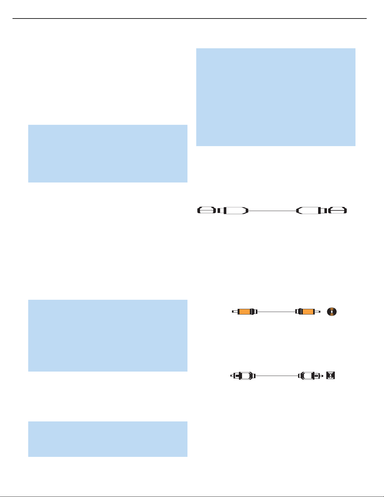
Optical
Optical digital
audio cable
Coaxial
Coaxial digital
audio cable
15
AVR247 harman/kardon
CONNECTIONS
Audio Connections
There are two formats for audio connections: digital and analog. Digital
audio signals are of higher quality, and are required for listening to
sources encoded with digital surround modes, such as Dolby Digital and
DTS. There are three types of digital audio connections: HDMI, coaxial
and optical. Any one type of digital audio connection may be used for
each source device, but never more than one for the same source.
However, it’s okay to make both analog and digital audio connections
at the same time to the same source.
NOTE: Since the AVR 247 is capable of processing the audio
and video portions of most HDMI signals, if your video display
device has an HDMI input, you may make a single HDMI
connection from your source device (such as a DVD player) to
the AVR. In that case, no separate digital audio connection is
required. Make sure to turn the volume on your television all
the way off.
Digital Audio
The AVR 247 is equipped with two HDMI (High-Definition Multimedia
Interface) inputs, and one output. HDMI is capable of carrying digital
audio and video information using a single cable, thus delivering the
highest possible quality picture and sound.
There are different versions of HDMI, depending on the capability of
the source device and the type of signal it is capable of transmitting
via the HDMI connection.
In addition, receivers and processors such as the AVR 247 may handle
the incoming signal in several different ways, depending on their capability
as well. Thanks to its powerful processor, the AVR 247 is capable of
processing both the audio and video components of the HDMI data,
minimizing the number of cable connections in your system.
If your digital cable television set-top box outputs 1080i or higher
video via component video outputs and is not equipped with an
HDMI output, contact your cable operator for a replacement.
For Xbox 360 and satellite television customers, either change
the settings on your source device to ensure that it outputs only
720p video through its component video outputs, which the
AVR can convert to the HDMI format, or connect the AVR’s
Component Video Monitor Outputs to the video display.
Although you could connect the source device’s component
video outputs directly to your video display, you would then have
to select the correct video input on the display, depending on
which source input on the AVR was in use.
The physical HDMI connection is simple.The connector is shaped for
easy plug-in (see Figure 4). If your video display has a DVI input, you
may use an HDMI-to-DVI adapter (not included) to connect it to the AVR’s
HDMI Output. HDMI cable runs are usually limited to about 10 feet.
The AVR 247 is Simplay HD-verified for compatibility via the HDMI
connection with other Simplay HD-verified products.
Figure 4 – HDMI Connection
If your video display or source device is not HDMI-capable, use one of
the analog video connections (composite, S- or component video) and,
if available on your source device, either a coaxial or optical digital audio
connection.
Coaxial digital audio jacks are usually color-coded in orange. Although
they look similar to analog jacks, they should not be confused, and you
should not connect coaxial digital audio outputs to analog inputs or
vice versa. See Figure 5.
NOTE: Some multichannel audio devices, such as DVD-Audio,
SACD, HD-DVD or Blu-ray Disc players, output some audio
formats only through the source’s multichannel analog outputs.
These include DVD-Audio players with HDMI version 1.0, and
HD-DVD and Blu-ray Disc players that do not decode the digital
audio. In those cases, make a separate analog audio connection
in addition to the HDMI connection, which is still used for video
or if you wish to listen to Dolby Digital, DTS or PCM materials
that may be stored on the disc.
In addition, the AVR 247 will convert analog video signals to the HDMI
format, upscaling to high-definition 720p resolution. Digital source signals
with 1080i or 1080p resolution are passed via the HDMI Output to
your display at their original high-quality resolution, depending on your
display’s capabilities. You may view the AVR 247’s own on-screen
display menus using the HDMI output.
IMPORTANT NOTE: The AVR 247 cannot convert 1080i or
1080p analog video signals to the HDMI format, and downconverts
them to 720p for the Component Video Outputs. This affects users
®
of Microsoft
18
Xbox®360 systems and some older set-top boxes.
Figure 5 – Coaxial Digital Audio
Optical digital audio connectors are often covered by a shutter to protect
them from dust. The shutter opens as the cable is inserted. Input connectors are color-coded using a black shutter, while outputs use a gray
shutter. See Figure 6.
Figure 6 – Optical Digital Audio
Due to the nature of digital signals as binary bits, they aren’t subject
to signal degradation the way analog signals are.Therefore, the quality
of all digital audio connections should be the same, although it is important to limit the length of the cable.Whichever type of connection you
choose, Harman Kardon recommends that you always select the highest
quality cables available within your budget.
18
Page 16
Composite
video cable
Multichannel
analog audio
cable (RCA)
Front Surround Center
Subwoofer
L
R
Analog audio
cable (RCA)
16
AVR247 harman/kardon
CONNECTIONS
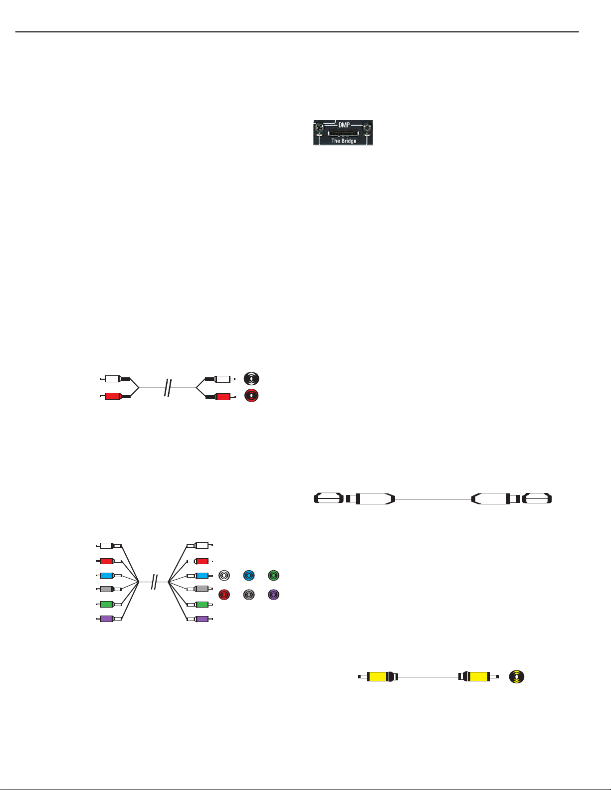
Analog Audio
Analog connections require two cables, one for the left channel (white)
and one for the right channel (red). These two cables are often attached
to each other for most of their length. See Figure 7.
Most sources that have digital audio jacks also have analog audio jacks,
although some older types of sources, such as tape decks, have only
analog jacks. For sources that are capable of both digital and analog
audio, you may wish to make both connections.
The analog audio connection is strongly recommended if you intend to
use the source with the multiroom system. It’s required if you will be
using the multiroom preamp outputs with an external amplifier to power
your remote speakers, as the AVR 247’s multiroom system is not capable of converting the digital signal to analog format. It’s suggested that
you also use the analog audio connections when using the surround
back/multiroom speaker outputs, in case another two-channel digital
audio source is in use in the main listening area. The AVR 247 is only
capable of processing one PCM source at a time.
If you wish to record materials from DVDs or other copy-protected
sources, you may only do so using analog connections. Remember to
comply with all copyright laws, if you choose to make a copy for your
own personal use.
messages displayed on the front panel and on a video display connected
to the AVR. The Bridge outputs analog audio to the AVR 247, and it is
available to the multiroom system.
Figure 9 – The Bridge
Video Connections
Although some sources produce an audio signal only (e.g., CD player,
tape deck), many sources output both audio and video signals (e.g.,
DVD player, cable television box, HDTV tuner, satellite box, VCR, DVR).
In addition to the audio connection, connect one type of video connection for each source (never more than one at the same time for any
source).
Digital Video
If you have already connected a source device to one of the HDMI
inputs as explained in the Digital Audio Connections section, then you
have automatically made a video connection at the same time, as the
HDMI signal includes both digital audio and video components.
If the source device is not capable of transmitting its digital audio signal
through the HDMI connection, then use one of the coaxial or optical
digital audio inputs for the source.
Figure 7 – Analog Audio
Multichannel analog connections are used with some high-definition
sources where the copy-protected digital content is decoded inside the
source.These types of connections are usually used with DVD-Audio,
SACD, Blu-ray Disc, HD-DVD and other multichannel players. See
Figure 8. However, the multichannel analog audio connection is not
required for DVD-Audio players compliant with HDMI version 1.1 or
better, or HD-DVD and Blu-ray Disc players that decode the digital audio
internally and output linear PCM signals in digital format. Consult the
owner’s guide for your disc player for more information.
Figure 8 – Multichannel Analog Audio
Harman Kardon receivers also include a proprietary, dedicated audio
connection called “The Bridge/DMP”. If you own an iPod with a dock
connector, you may purchase The Bridge separately and connect it to
The Bridge/DMP port on the receiver. See Figure 9. Dock your iPod
(not included) in The Bridge, and you may enjoy your audio and video
materials through your high-performance audio/video system. You may
even use the AVR 247 remote to control the iPod, with navigation
19
If a multichannel analog audio connection is required for certain lossless
formats (e.g., DVD-Audio, SACD, HD-DVD or Blu-ray Disc), you may
make both connections, but you must also make an analog video connection. To listen to the multichannel disc, first select the analog video
source input, then select the 6-/8-channel analog audio inputs, and the
AVR will retain the last video source you selected other than HDMI.
The AVR 247 is Simplay HD-verified for compatibility via the HDMI
connection with other Simplay HD-verified products.
Figure 4 (repeated) – HDMI Connection
Analog Video
There are three types of analog video connections: composite video,
S-video and component video.
Composite video is the basic connection most commonly available.The
jack is usually color-coded yellow, and looks like an analog audio jack,
although it is important never to confuse the two. Do not plug a composite
video cable into an analog or coaxial digital audio jack, or vice versa.
Both the chrominance (color) and luminance (intensity) components of
the video signal are transmitted using a single cable. See Figure 10.
Figure 10 – Composite Video
S-video, or “separate” video, transmits the chrominance and luminance
components using separate wires contained within a single cable.The
Page 17
Component
video cable
S-video cable
17
AVR247 harman/kardon
CONNECTIONS
plug on an S-video cable contains four metal pins, plus a plastic guide
pin. Be careful to line up the plug correctly when you insert it into the
jack on the receiver, source or video display. See Figure 11.
Figure 11 – S-Video
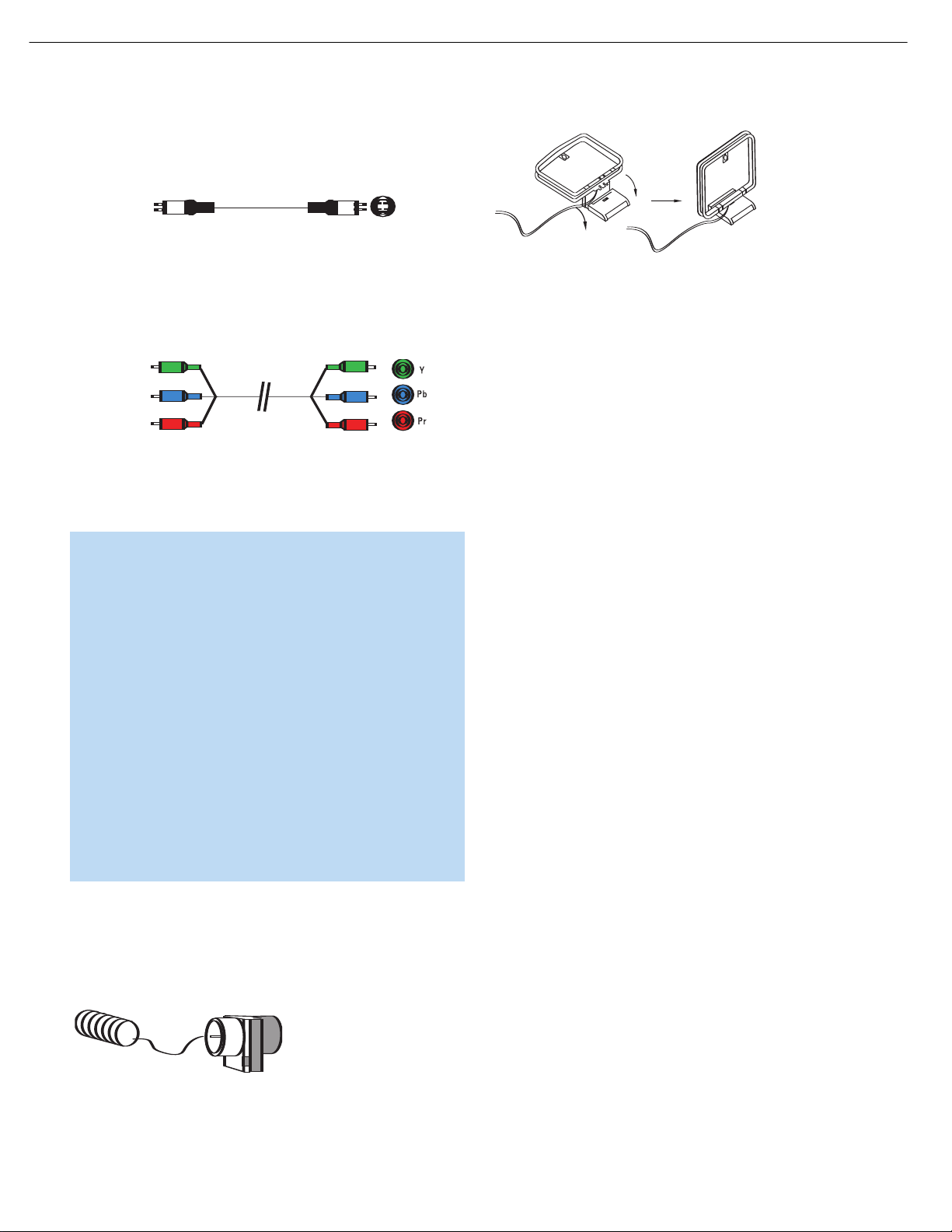
Component video separates the video signal into three components –
one luminance (“Y”) and two sub-sampled color signals (“Pb” and “Pr”) –
that are transmitted using three separate cables.The “Y” cable is colorcoded green, the “Pb” cable is colored blue and the “Pr” cable is
colored red. See Figure 12.
Figure 12 – Component Video
If it’s available on your video display, HDMI is recommended as the best
quality connection, followed by component video, S-video and then
composite video.
NOTES:
• Due to copy-protection restrictions, there is no output at the
Component Video Monitor Outputs for copy-protected sources.
• High-resolution 1080i and 1080p video signals are not available at the HDMI Output, and are downconverted to 720p for
the Component Video Outputs. If your source outputs analog
high-resolution video, either use the Component Video
Outputs, change the output resolution of your source device
to 720p, or connect your source’s component video outputs
directly to your video display.
• Due to the design of some video displays, analog 480p or
720p component video source signals may produce artifacts
when used with the AVR’s analog video outputs (composite,
S-video or component video). If this occurs, try changing the
Video Mode setting in the INPUT SETUP menu, or connecting
the source device’s video output directly to your video display.
However, for best results, we recommend that you consider
upgrading to an HDMI-capable video display.
Figure 14 – AM Antenna
RS-232 Serial Port
The RS-232 serial port on the AVR 247 is used only for data. If
Harman Kardon releases a software upgrade for the receiver’s operating
system at some time in the future, the upgrade may be downloaded
to the AVR using this port. Complete instructions will be provided at
that time.
Antennas
The AVR 247 uses separate terminals for the included FM and AM
antennas that provide proper reception for the tuner.
The FM antenna uses a 75-ohm F-connector. See Figure 13.
Figure 13 – FM Antenna
The AM loop antenna needs to be assembled. Then connect the two
leads to the screw terminals on the receiver. See Figure 14.
20
Page 18
FM
A
M
AVR 247
SUB
AVR 247
AVR 247
SR
SL
FR FL
SBR
SBL
C
18
AVR247 harman/kardon
INSTALLATION
You are now ready to connect your various components to your receiver.
Before beginning, make sure that all components, including the AVR 247,
are turned completely off and their power cords are unplugged. Don’t
plug any of the power cords back in until you have finished
making all of your connections.
Remember that your receiver generates heat while it is on. Select a
location that leaves several inches of space on all sides of the receiver.
It is preferable to avoid completely enclosing the receiver inside a
cabinet. It is also preferable to place components on separate shelves
rather than stacking them directly on top of the receiver. Some surface
finishes are delicate.Try to select a location with a sturdy surface finish.
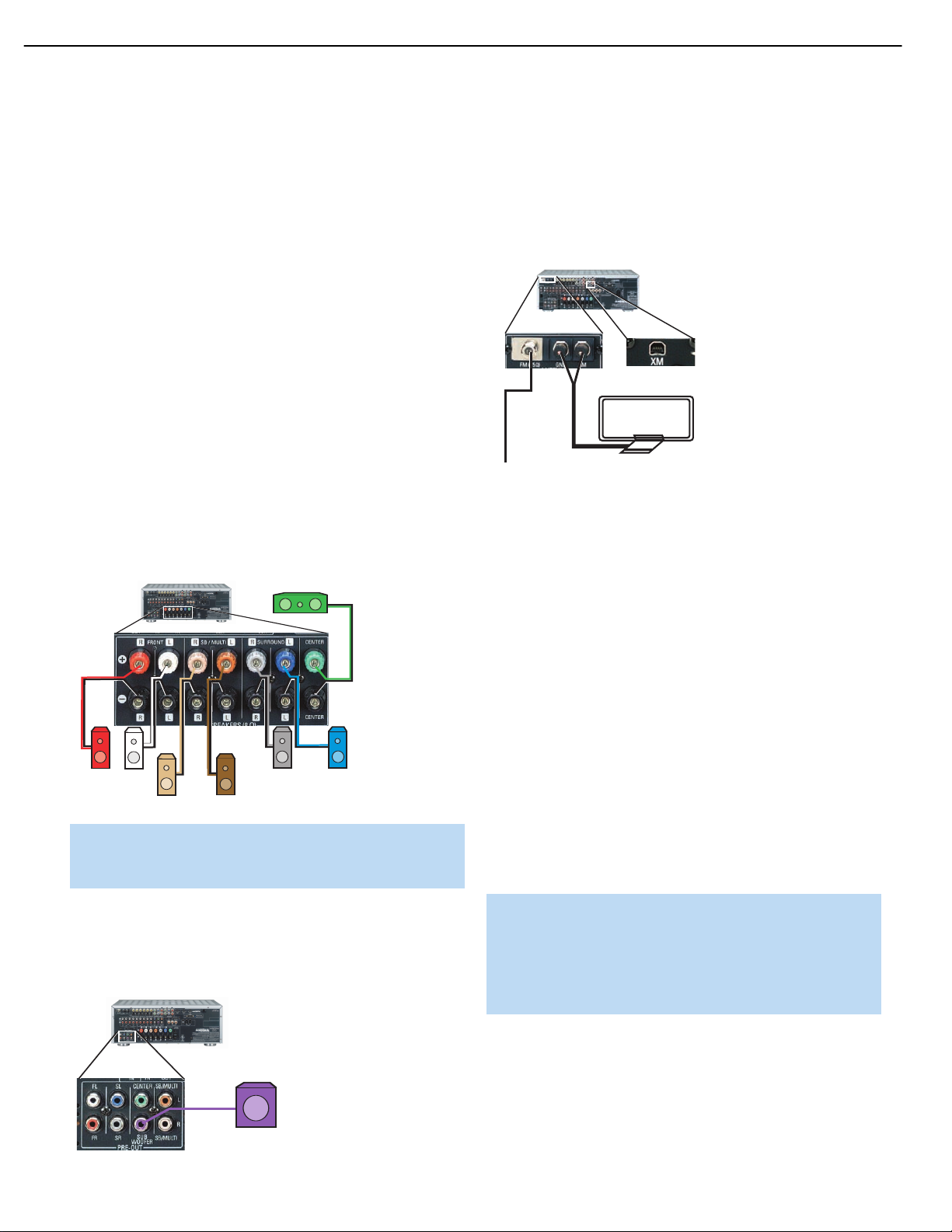
Step One – Connect the Speakers
If you have not yet done so, place your speakers in the listening room,
as described in the Speaker Placement section above.
Connect the center, front left, front right, surround left, surround
right, surround back left and surround back right loudspeakers to the
corresponding speaker terminals on the AVR 247. See Figure 17.
Remember to maintain the proper polarity by always connecting the
positive and negative terminals on each speaker to the positive and
negative terminals on the receiver. Use the Connection Color Guide
on page 17 as a reference.
Step Three – Connect the Antennas
Connect the FM and AM antennas to their terminals. If you have purchased
an XM antenna module designed for connection to an XM Ready device,
such as the AVR 247, you may connect it now.To enjoy XM Radio,
remember to purchase a subscription and activate your antenna module.
More information is available at www.xmradio.com.See Figure 19.
Figure 19 – Antenna Connections
Step Four – Connect the Source Components
Use the Table A4 worksheet in the Appendix to note which connections
you will use for each of your source devices.
For each source, select a source input (Video 1, Video 2, Video 3, etc.).
In Table 2 we recommend connecting certain types of sources to certain
source inputs to make it easier to program and use the remote control.
Figure 17 – Speaker Connections
NOTE: If you only have one surround back speaker, wait until
after you have run EzSet/EQ in the Initial Setup section before
connecting it to the Surround Back Left speaker outputs.
Step Two – Connect the Subwoofer
Connect the Subwoofer Output on the AVR 247 to the line-level input on
your subwoofer. See Figure 18. Consult the manufacturer’s guide for the
subwoofer for additional information.
Figure 18 – Subwoofer Connection
Decide which audio connections you will use. If your source device has
them, use one of the HDMI, coaxial digital or optical digital audio connections. Referring to Table 2, we recommend you connect the DVD source
to the Coaxial 1 input jack, and the source designated Video 2 to the
Optical 1 input jack. If you are using the HDMI inputs, then in most cases
no other audio connection is required. If your source outputs video but
not audio via its HDMI connection, then select any available coaxial or
optical digital audio input on the AVR to use with the source. If your HDMI
source plays DVD-Audio, SACD, HD-DVD, Blu-ray Discs or another multichannel audio format, connect its multichannel analog audio outputs to
the AVR 247’s 6-/8-Channel Inputs, and connect one of its analog video
outputs to a source input on the AVR 247 (e.g., Video 3). When you
select that source input, e.g., Video 3, select the 6-/8-Channel Inputs,
and the AVR will automatically use the analog video input.
NOTE: The multichannel analog audio connection is not
required for DVD-Audio players compliant with HDMI version
1.1 or better, or HD-DVD and Blu-ray Disc players that decode
the digital audio internally and output linear PCM signals in
digital format. Consult the owner’s guide for your disc player
for more information.
In addition to the digital audio connections, we recommend that you
connect the analog audio connections for each source, as a backup to
the digital connections, for recording, for use with the multiroom system,
or in the event that you use all six of the digital audio inputs for other
devices. For sources that don’t have digital audio outputs, you must use
the analog audio connections.
Page 19

19
AVR247 harman/kardon
INSTALLATION
For each video source, select one type of video connection. HDMI video
is preferred, but both your source device and your video display must
have this type of video capability. If either device does not, then use
component video, S-video or composite video.
Referring to Table 2, we recommend that you connect the DVD source
to the Component Video 1 inputs, the Video 1 source to the Component
Video 2 inputs, and the Video 2 source to the Component Video 3 inputs.
Any HDMI-capable source devices should be connected to one of the
two HDMI inputs.All other source devices should be connected to either
NOTE: It’s possible for a source to use none of the connections
named for that source. For example, you might connect your
DVD player to the Component Video 1 inputs and the Coax 1
digital audio input. However, we will refer to this source as
“DVD,” and in the Initial Setup section you will program the
receiver so that these connections are assigned to the DVD
source.When you select “DVD” as your source using the front
panel or the remote, the correct connections for your DVD
player will be used.
the component, S- or composite video input for that source. However,
you may make whatever video connections are best for your system.
Table 2 – Recommended Source Component Connections
Source Device Type AVR 247 Source Input Audio Connections Video Connections
VCR, DVR, PVR, Video 1 • Video 1 Analog (inputs and outputs) • One of Component Video 2,Video 1 S-video
TiVo or other and or Video 1 Composite Video Input
audio/video recorder • Any one available coaxial or optical digital, • For recording, use Video 1 S-video or
audio input, with corresponding coax Composite Video Output, and do not use
or optical digital output component video connections at all
Cable TV, satellite TV, Video 2 • Video 2 Analog Inputs and • One of Component Video 3, Video 2
HDTV or other • Optical 1 Input S-video or Video 2 Composite Video Input
device that delivers
television programs
TV or other audio/video Video 3 • Video 3 Analog Inputs and • Video 3 S-video or Video 3 Composite
device (only when used • Any one available coaxial or optical Video Input
as a source) digital audio input • Not required if sources is a TV
TV, game console, Video 4 (front-panel jacks) • Video 4 Analog Inputs and • Video 4 S-video or Video 4 Composite Video
camera or other • Either Coax 3 or Optical 3 Input Input
audio/video device • Not required if sources is a TV
DVD Audio/Video, DVD • DVD Analog Inputs • Component Video 1 Input
SACD, HD-DVD, • 6-/8-Channel Inputs (optional)
Blu-ray Disc • Coax 1 Input
HDMI-capable DVD HDMI 1 • HDMI 1 input • HDMI 1 Input
Audio/Video or HD-DVD
player or other audio/
video device
HDMI-capable DVD HDMI 2 • HDMI 2 input • HDMI 2 Input
Audio/Video or HD-DVD
player or other audio/
video device
CD player CD • CD Analog Inputs
CDR, MiniDisc, Tape • Tape Analog (inputs and outputs) and • Not required
cassette • Any one available coaxial or optical digital,
• 6-/8-Channel Inputs (optional)
• 6-/8-Channel Inputs (optional)
and • Not required
• Any one available coaxial or optical
digital audio input
audio input, with corresponding coax
or optical digital output
and
Page 20
20
AVR247 harman/kardon
INSTALLATION
We recommend connecting your various sources using the connections
shown in Table 2 in order to simplify programming your receiver
and remote control. However, you may connect any device to any
source input.
NOTE: The AVR 247 is equipped with a total of six digital audio
inputs, not including the HDMI inputs: four on the rear panel
(Coaxial 1 and 2, Optical 1 and 2) and two on the front panel
(Coaxial 3 and Optical 3). However, there are a total of nine
sources that may be connected to devices that have digital
audio outputs.We recommend certain digital audio connections
simply because, as reflected in Table A1 of the Appendix, those
digital audio inputs are assigned to those sources by default at
the factory. But any digital audio input (except HDMI) may be
reassigned to any source. Since you may not be using all nine
source inputs, you may reassign a digital audio input that is
recommended for a source you aren’t using to another device.
Table 2 is a guide; you may need to make adjustments to fit
your system.
Video 1 Source
Since this source includes audio and video recording output jacks, it is
best suited to a video recorder, such as your VCR or DVR/PVR.
Referring to Table 2, connect your recorder to the Video 1 Analog Audio
inputs and outputs
input (and corresponding digital audio output). See Figure 20. Use either
the Video 1 S-video or composite video input and output if you wish to
make recordings. If you don’t plan on recording, you may use the
Component Video 2 inputs.
and to any available coaxial or optical digital audio
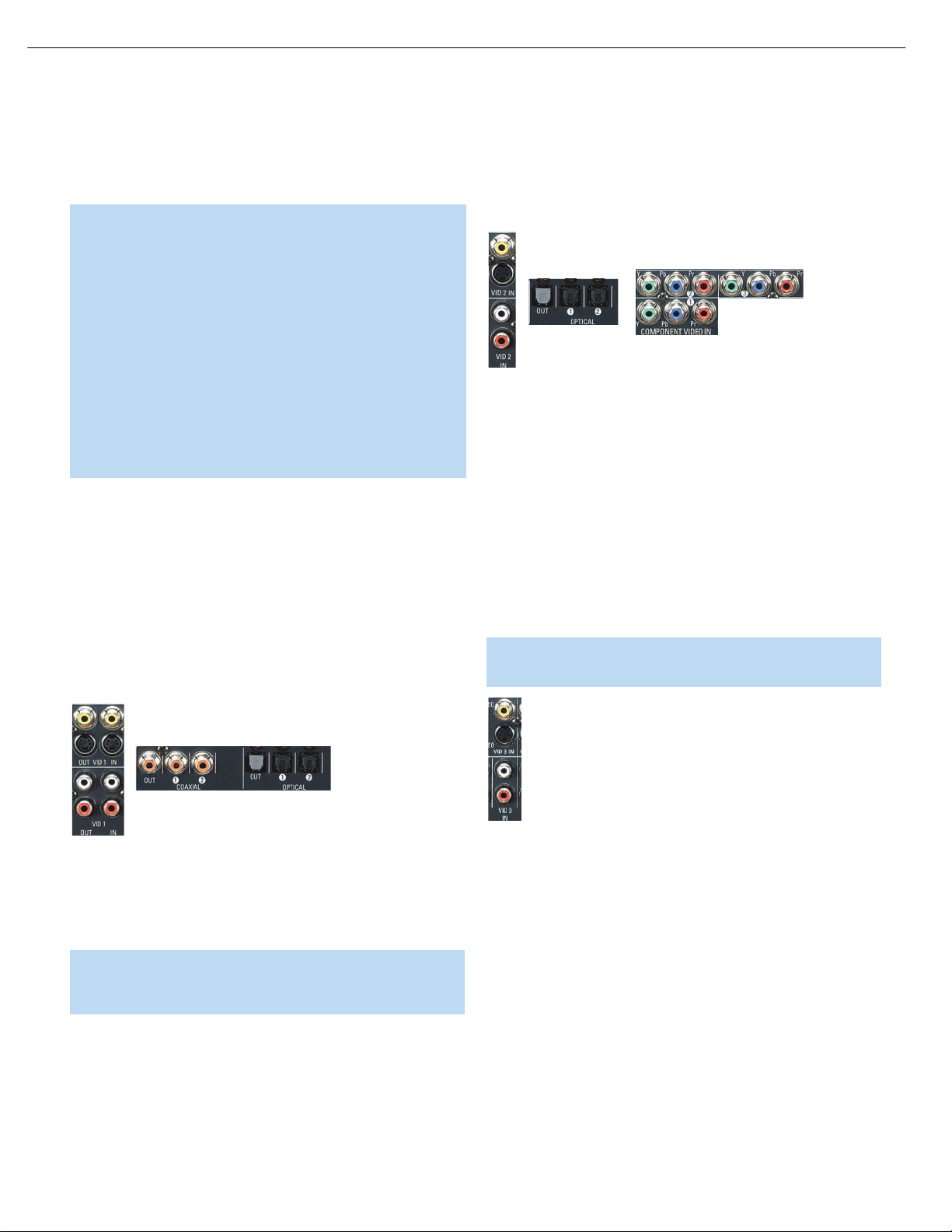
Referring to Table 2, connect your set-top box to the Video 2 Analog
Audio inputs
the Component Video 3 inputs. Otherwise, connect the set-top box’s
S-video or composite video output to the matching Video 2 video input.
See Figure 21.
Figure 21 – Video 2 A/V, Digital Audio and Component Video Inputs
and to the Optical 1 Digital Audio input. If possible, use
Video 3 Source
The Video 3 source is used only for playback. The remote control
is programmed to operate a TV, but you may connect any audio/video
source device to the Video 3 inputs and use the device’s own remote
to control it.
If you receive your television programming using your TV with an antenna
or direct cable connection, connect the analog audio outputs (if available
on your TV) to the Video 3 Analog Audio inputs. See Figure 22.
connect any video output on the television set to any video input on the
receiver. See Step Five for information on connecting the receiver’s
video monitor outputs to the TV.
NOTE: You may connect any video source other than a display
device to the Video 3 S-video or composite video inputs.
Do not
Figure 20 – Video 1 A/V Inputs and Outputs, and Digital Audio Inputs and Outputs
Remember to connect the audio and video output jacks on your
recorder to the Video 1 or digital audio
audio and video
output jacks on the AVR.
audio
NOTE: It isn’t possible to make recordings using HDMI or component video connections. Keep this in mind as you connect other
source devices that you may wish to make recordings from.
input jacks on your recorder to the Video 1 or digital
input jacks on the AVR, and the
Video 2 Source
The Video 2 source is used only for playback. The AVR 247 remote
control is programmed to operate many brands and models of cable
and satellite television devices, and we recommend connecting your
cable or satellite set-top box to this source.
Figure 22 – Video 3 A/V Inputs
Video 4 Source
The Video 4 source is used only for playback. It is also generally
reserved for components that are only temporarily connected to the
receiver, such as cameras and game consoles. When not in use, you
may place the supplied covers over the front-panel Video 4 jacks for a
cleaner appearance. Simply snap the covers in place. When you wish to
use the jacks, gently press on the left side of each cover to pivot it out
for removal.
Referring to Table 2, connect your camera or game console to the
Video 4 Analog Audio inputs
digital audio input. Connect the component’s S-video or composite
video output to the matching Video 4 video input. See Figure 23.
and to either the Coaxial 3 or Optical 3
Page 21
21
AVR247 harman/kardon
INSTALLATION
HDMI 1 and 2
The HDMI sources are used with devices that are capable of outputting
digital audio and video through an HDMI connection, such as an HD-DVD
Figure 23 – Video 4 A/V and Digital Audio Inputs
NOTE: The Video 4 Input Selector on the remote may only be
programmed to operate a television or video display.
IMPORTANT NOTE FOR MICROSOFT®XBOX®360 USERS:
The Microsoft Xbox 360 gaming system is capable of outputting
high-definition 1080i and 1080p video signals using the analog
component video outputs. Since the AVR 247 is not capable of
converting these analog component video signals to the HDMI
format and downconverts them to 720p for the Component
Video Outputs, to view your Xbox 360’s video output, either
connect the Xbox’s component video outputs to your video display,
or change your Xbox 360’s settings so that it outputs 720p
video, which the AVR 247 can then convert to the HDMI format.
DVD
The DVD source is used for a DVD player. If you have a high-resolution
multichannel device, such as a Blu-ray Disc or HD-DVD player, you may
connect it to the DVD source.
Referring to Table 2, connect your DVD player to the DVD Analog
Audio inputs
the Component Video 1 inputs. Otherwise, connect the DVD player’s
S-video or composite video output to the matching DVD video input.
See Figure 24.
and to the Coaxial 1 Digital Audio input. If possible, use
or Blu-ray Disc player or HDTV tuner. The HDMI sources are not used
with any of the 2-channel analog audio or video inputs on the AVR 247.
Make sure your video display is HDMI-capable, and for many source
devices, the display must be HDCP-compliant (High-Bandwidth Digital
Content Protection) in order to display copy-protected materials. If the
source device is not capable of outputting digital audio via its HDMI
output, connect its coaxial or optical digital audio output to an available
input on the AVR. If the source device plays multichannel discs (e.g.,
DVD-Audio, SACD, HD-DVD, Blu-ray Disc), connect its multichannel
analog audio outputs to the AVR 247’s 6-/8-Channel Inputs (but see
note above). Connect one of the source’s analog video outputs to
a source input on the AVR (e.g., Component Video 3 or Video 3) and
select that source input, then select the 6-/8-Channel Inputs for audio;
the AVR 247 will retain the last video selection other than HDMI.
See Figure 26.
The AVR 247 is Simplay HD-verified for compatibility via the HDMI
connection to other Simplay HD-verified products.
If your video display is equipped with a DVI (Digital Video Interface)
input, you may use an HDMI-to-DVI adapter (not included).
Figure 26 – HDMI and Digital Audio Inputs
CD
Figure 24 – DVD A/V, Digital Audio and Component Video Inputs
If your DVD player plays high-resolution audio discs, such as SACD
or DVD-Audio, or when an HD-DVD or Blu-Ray Disc player is used,
connect the 6- or 8-channel analog audio outputs on the player to the
6-/8-channel analog audio inputs on the receiver, in order to enjoy
these discs to their fullest. See Figure 25.
Figure 25 – 6-/8-Channel Analog Audio Inputs
NOTE: The multichannel analog audio connection is not
required for DVD-Audio players compliant with HDMI version
1.1 or better, or HD-DVD and Blu-ray Disc players that decode
the digital audio internally and output linear PCM signals in
digital format. Consult the owner’s guide for your disc player
for more information.
The CD source is used for a strictly audio device, such as a CD player.
Referring to Table 2, connect your CD player to the CD Analog Audio
and to any available digital audio input. See Figure 27.
inputs
Figure 27 – CD Audio Inputs and Digital Audio Inputs
No video connections are needed.
Tape
The Tape source is used for audio-only recorders, such as a CDR,
MiniDisc or cassette deck.
Referring to Table 2, connect your recorder to the Tape Analog Audio
inputs and outputs, and to any available digital audio input (and corresponding digital audio output). See Figure 28.
Figure 28 – Tape Audio Inputs and Outputs, and Digital Audio Inputs and Outputs
Page 22
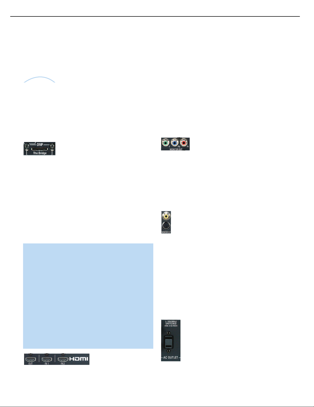
The
Bridge
TM
22
AVR247 harman/kardon
INSTALLATION
Remember to connect the output jacks on your recorder to the Tape
or digital audio
recorder to the Tape or digital audio
No video connections are needed.
With Harman Kardon’s optional The Bridge, you can enjoy audio, video
or still images stored on your iPod (not included), use your AVR 247
remote control to operate the iPod, and even charge the iPod while
it’s docked in The Bridge.
Simply plug the proprietary cable from The Bridge into the special
The Bridge/DMP connector on the rear of the AVR 247. See Figure 29.
Refer to the owner’s manual for The Bridge to select the appropriate
insert to match your iPod.
input jacks on the AVR, and the input jacks on your
output jacks on the AVR.
Figure 29 – The Bridge/DMP Connector
Step Five – Connect the Video Display
Only video connections should be made between the receiver and
your video display (TV), unless your TV is the source for your television
programming (see Video 3 Source on page 24).
If you used an HDMI video connection for any of your sources, then
connect the HDMI Output on the AVR to an HDMI input on your video
display. See Figure 30. Consult the owner’s guide for your television to
learn the proper procedure for disabling or muting the audio. Unless you
have a non-HDMI source device that outputs 1080i or higher video via
an analog component video connection (see note below), no other video
connections are required, thanks to the AVR 247’s ability to transcode
most analog video signals to HDMI, and you may proceed to Step Six.
IMPORTANT NOTE: The AVR 247 cannot convert 1080i or
1080p analog video signals to the HDMI format and downconverts them to 720p for the Component Video Outputs. This
affects users of Microsoft Xbox 360 systems and some older
set-top boxes.
If your digital cable television set-top box outputs 1080i or higher
video via component video outputs and is not equipped with an
HDMI output, contact your cable operator for a replacement.
For Xbox 360 and satellite television customers, change the
settings on your source device to ensure that it outputs only
720p video through its component video outputs, which the
AVR can convert to the HDMI format. Although you could connect the source device’s component video outputs directly
to your video display, you would then have to select the correct
video input on the display, depending on which source input on
the AVR was in use.
First, determine what types of video your display is capable of handling.
Remember that component video is preferred, followed by S-video
and then composite video. Ideally, this guided you in selecting the video
connections for your sources.
Next, note which types of video connections you used for your source
devices. Make sure you didn’t use a better type of video connection
for a source than your video display can handle. If so, disconnect the
source and use a video connection that’s compatible with your display.
If you used component video for any sources, connect the Component
Video Monitor Outputs on the receiver to one set of component video
inputs on your display. See Figure 31. The AVR 247 is able to transcode
composite and S-video sources to component video. If your video display
has component video inputs, then you only need to connect the Component
Video Monitor Outputs and you may proceed to Step Six.
Figure 31 – Component Video Monitor Outputs
If you used S-video for any sources, connect the S-video Monitor Output
on the receiver to an S-video input on your display. See Figure 32. The
AVR 247 converts composite video sources to S-video. If your video
display has S-video inputs, then you only need to connect the S-Video
Monitor Output and you may proceed to Step Six.
If you used composite video for any sources, but not component video
or S-video, connect the Composite Video Monitor output on the receiver
to a composite video input on the display. See Figure 32.
Figure 32 – S-Video and Composite Video Monitor Outputs
Consult the manual for your TV to make sure you understand how to
select each video input.
Step Six – Plug in AC Power
Having made all of your wiring connections, it is now time to plug each
component’s AC power cord into a working outlet.
You may plug one device into the AC Switched Accessory Outlet on the
rear of the AVR 247. See Figure 33. Make sure this device draws no
more than 50 watts.The device should have its mechanical or master
power switch turned on, and it will power on any time the AVR 247 is
turned on.
Figure 30 – HDMI Output
If your television does not have HDMI or DVI video inputs, you will need
to make a video connection for each type of video used for your sources.
Figure 33 – Switched AC Accessory Outlet
Before plugging the AVR 247’s AC Power Cord into an electrical outlet,
make sure that the Master Power Switch on the front panel is popped
Page 23

23
AVR247 harman/kardon
INSTALLATION
out so that the word OFF appears on its top. Gently press the button to
turn the switch off. This will prevent the possibility of damaging the AVR
in case of a transient power surge.
Step Seven – Insert Batteries in Remote
The AVR 247 remote control uses three AAA batteries, which are included.
To remove the battery cover located on the back of the remote,
firmly press the ridged depression and slide the cover toward the top
of the remote.
Insert the batteries, as shown in Figure 34, making sure to observe
the correct polarity.
Figure 34 – Remote Battery Compartment
When using the remote, remember to point the lens toward the front
panel of the AVR 247. Make sure no objects, such as furniture, are
blocking the remote’s path to the receiver. Bright lights, fluorescent lights
and plasma video displays may interfere with the remote’s functioning.
The remote has a range of about 20 feet, depending on the lighting
conditions. It may be used at an angle of up to 30 degrees to either
side of the AVR.
When the remote is in the device mode for the primary source, e.g., DVD,
pressing the device selector will cause it to light up in red. When the
remote is in the secondary source’s device mode, the selector will light
up in green when pressed.
To switch between the primary and secondary device modes, press the
selector twice quickly in succession. The selector will retain this selection
until the next time you toggle between the primary and secondary device
modes.That is, if you press the DVD/CD Selector twice quickly so that
the CD source is activated, then press another source selector, such as
Video 1, the next time you press the DVD/CD Selector, the remote will
return to the CD device mode.
The AVR 247’s remote is factory-programmed to control an iPod
docked in The Bridge and many Harman Kardon DVD and CD players.
If you have other source devices in your system, follow these steps to
program the correct codes into the remote.
1. Using the codes in Tables A9–A16 of the Appendix, look up the
product type (e.g., DVD, cable TV box) and the brand name of your
source.The number(s) listed is/are potential candidates for the
correct code set for your particular device.
2. Turn on your source device.
3. This step places the remote in program mode, and varies slightly,
depending on which Input Selector is being programmed. Refer to
Figure 35.
a) DVD, Tape, Video 1, Video 2,Video 3 and Video 4 Sources:
Press and hold the Input Selector until the Program Indicator LED
starts to flash, then release it. Follow the directions in Step 4, below.
If the remote seems to operate intermittently, or if pressing a button
on the remote does not cause the AVR Selector or one of the Input
Selectors to light up, then make sure the batteries have been inserted
correctly, or replace all three batteries with fresh ones.
Step Eight – Program Sources Into the Remote
The AVR 247 remote not only is capable of controlling the receiver,
but it may also be programmed to control many brands and models of
VCRs, DVD players, CD players, cable boxes, satellite receivers, cassette
decks and TVs, as well as an iPod docked in The Bridge.
It may help to think of the remote as a book with pages. Each “page”
represents the button functions for a different device. In order to access
the functions for a particular device, you first need to turn to that page;
that is, switch the remote to that device mode. This is done by pressing
the AVR Button to access the codes that control the receiver, or the
Input Selector Buttons to access the codes for the devices programmed
into the remote.
You may have noticed that three of the Input Selectors look different
from the others (see Figure 35). For the DVD/CD, TAPE/The Bridge and
HDMI 1/HDMI 2 Selectors, there is a primary source, the name of which
is printed on the button, and a secondary source, the name of which is
printed in green above the button.
b) CD Source: Press the DVD/CD Input Selector twice quickly so
that it turns green, hold it until the Program LED starts to flash,
then release. Follow the directions in Step 4, below.
c) HDMI 1 Source: Press and hold the Input Selector until it turns
red and the Program LED starts to flash, then release it. Next,
press the Input Selector that corresponds to the device type you
want to program into the HDMI 1 mode, i.e., DVD, VCR/PVR or
CBL/SAT. Then follow the directions in Step 4, below.
d) HDMI 2 Source: Press and release the Input Selector once, then
quickly press the Input Selector again so that it turns green. Hold
it until the Program LED starts to flash, then release it. Next, press
the Input Selector that corresponds to the device type you want to
program into the HDMI 2 mode, i.e., DVD, VCR/PVR or CBL/SAT.
Then follow the directions in Step 4, below.
Figure 35 – Input Selectors
Page 24
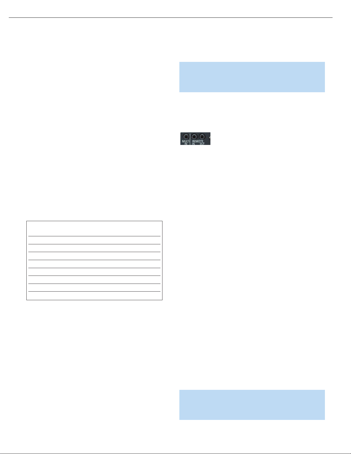
24
AVR247 harman/kardon
INSTALLATION
4. Enter a code from Step 1, above.
a) If the device turns off, then press the Input Selector again to accept
the code; it will flash. The remote will exit the Program mode.
b) If the device does not turn off, try entering another code. If you
run out of codes, you may search through all of the codes in the
⁄
¤
remote’s library for that product type by pressing the
Button repeatedly until the device turns off. When the device turns
off, enter the code by pressing the Input Selector, which will flash.
The remote then exits Program mode.
5. Once you have programmed a code, it’s a good idea to try using
some other functions to control the device. Sometimes, manufacturers
use the same Power code for several different models, while other
codes will vary.You may wish to repeat this process until you’ve
programmed a satisfactory code set that operates most of the
functions you frequently use.
6. You may find out which code number you have programmed by
pressing and holding the Input Selector to enter the Program mode.
Then press the Set Button, and the LED will flash in the code
sequence. One flash represents “1”, two flashes for “2”, and so forth.
A series of many fast flashes represents “0”. Record the codes
programmed for each device in Table 3.
Table 3 – Remote Control Codes
Source Input Product Type Remote
(circle one) Control Code
Video 1 VCR, PVR
Video 2 Cable, Satellite
Video 3 TV
Video 4 TV
HDMI 1 DVD, VCR, PVR, CBL, SAT
HDMI 2 DVD, VCR, PVR, CBL, SAT
DVD DVD
CD CD, CDR
or
device without having to switch the remote’s device mode. See pages
58– 59 for instructions on these advanced programming functions.
NOTE: The AVR 247 remote is preprogrammed to operate the
transport controls of Harman Kardon DVD players when the AVR,
the Video 2 (cable/satellite) or the Video 3 (TV) source is selected.
You may change this punch-through programming at any time.
Step Nine – Remote IR Inputs and Output (Optional)
The AVR 247 is equipped with a Remote IR Input, a Multiroom IR Input
and both full-carrier and stripped Remote IR Outputs to facilitate use of
your system with a remote control in a variety of situations. See Figure 36.
Figure 36 – IR Inputs and Outputs
When the AVR 247 is placed in such a way that aiming the remote at the
front-panel IR sensor is difficult, such as inside a cabinet or facing away from
the listener, you may connect an external IR receiver, such as the optional
Harman Kardon HE 1000, to the Remote IR Input jack. When you are using
the AVR 247 in multiroom mode, you may connect an optional IR receiver,
keypad or other control device to the Multiroom IR Input for remote control
of the AVR 247 (and any sources connected to the AVR’s Remote IR
Output) from the remote zone.Any signals transmitted through the Multiroom
IR Input will only control source selection and volume for the remote zone.
If a source device is being shared with the main listening area, then any
control commands issued to that source will also affect the main room.
If any of your source devices are equipped with a compatible Remote
IR Input, you may use a 1/8" mini-plug interconnect cable (not included)
to connect the AVR’s Remote IR Output to the source device’s Remote
IR Input, which will pass any applicable remote signals transmitted
through the AVR to the source device. This enables you to control your
sources even when the AVR itself is controlled via an external IR receiver.
Check with the manufacturer of the source device for more information
on the type of IR signal expected. The AVR 247 will output a “stripped
carrier” IR signal through the Remote IR Output.
If you are unable to locate a code set that correctly operates your
source device, it will not be possible to use the AVR remote to control
that device. However, you may still connect the source to the AVR 247
and operate it using the device’s original remote control. Alternatively,
you may wish to consider purchasing Harman Kardon’s optional TC 30
activity-based remote, which is programmed by accessing a large database of product codes on the Internet. The TC 30 is also capable of
“learning” codes from your device’s original remote.
Most of the button labels on the remote describe the button’s function
when used to control the AVR 247. However, the button may perform a
very different function when used to control another device. Refer to the
Remote Control Function List, Table A8 in the Appendix, for a list of
each button’s functions with the various product types.
If you wish, you may program Macros, which are preprogrammed code
sequences that execute many code commands with a single button
press.You may also program “punch-through” codes, which allow the
remote to operate the volume, channel or transport controls of another
To control more than one source device using the Remote IR Output,
connect all sources in “daisy chain” fashion, with the AVR’s Remote
IR Output connected to the first device’s Remote IR Input, the second
device’s Remote IR Output connected to the next device’s Remote
IR Input, and so forth.
Step Ten – Install a Multiroom System (Optional)
The AVR 247 offers several methods of distributing music to other
listening areas in your home.As indicated in the subheading, a multiroom system is not required to enjoy the home theater experience.
If you prefer not to install a multiroom system at this time, skip to
Step Eleven to turn on the AVR 247 and configure it.
IMPORTANT SAFETY NOTE: Installing a multiroom system very
often requires running various cables inside walls.Always comply
with the appropriate safety codes when installing concealed wiring.
The AVR 247’s multiroom connections should be installed per the
Page 25
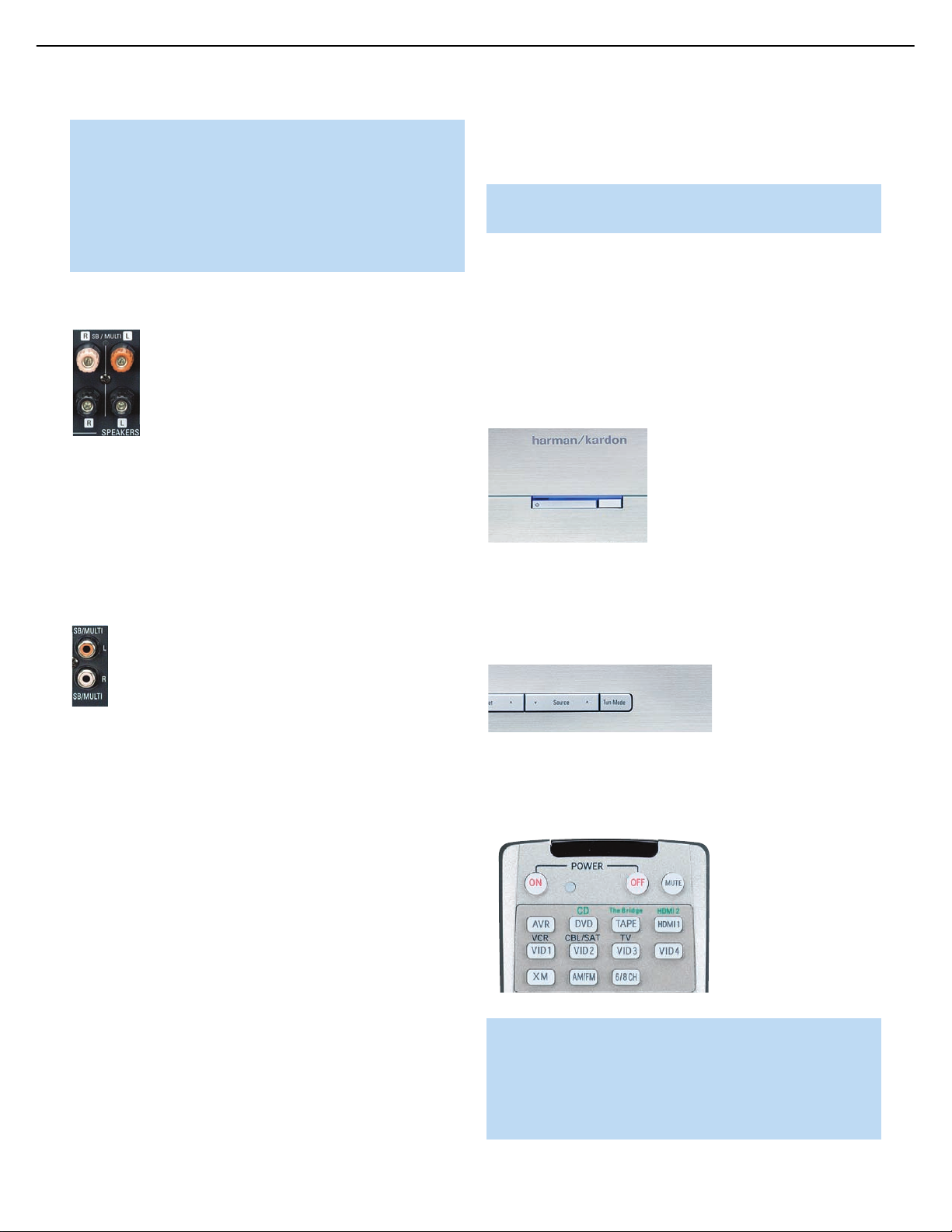
25
AVR247 harman/kardon
INSTALLATION
requirements of all applicable state and local building codes, as
well as NEC (National Electrical Code) requirements. Check with
your local authorities as needed to ensure that all wiring inside
walls is installed in compliance with the proper standards. Failure
to do so may present a potential safety hazard. If you have any
doubt about your ability to work with electrical and telecommunications wiring, you are advised to hire a professional licensed
electrician or custom installer to install the multiroom system.
1. Connect the remote room’s speakers directly to the Surround
Back/Multiroom Speaker Outputs. See Figure 37.
Figure 37 – Surround Back/Multiroom Speaker Outputs
If you do not require a full 7.1-channel system in your main listening
area, and you prefer not to purchase an external amplifier to power
a pair of remote speakers, you may reassign the AVR 247’s Surround
Back amplifier channels to power the speakers.Your main system will
be limited to 5.1 channels, which affects your ability to enjoy the
many DVDs and other programs recorded in 6.1 and 7.1 channels.
2. Connect an external amplifier to the Surround Back/Multiroom
Preamp Outputs. See Figure 38.
the remote room may turn the multiroom system on or off, select a
source input, control the source device connected to that input and
adjust the volume in the remote zone.
NOTE: Only analog audio sources are available to the multiroom
system.
Step Eleven – Turn On the AVR 247
Two steps are required the first time you turn on the AVR 247.
1. Gently press the Master Power Switch until the word OFF is no longer
visible.The Power Indicator above the two power switches should
light up in amber, indicating that the AVR is in Standby mode and is
ready to be turned on. See Figure 39. Normally, you may leave the
Master Power Switch in the ON position, even when the receiver is
not being used.
Figure 39 – Power Switches
2. There are several ways in which the AVR 247 may be turned on from
Standby mode.
a) Press the Standby/On Switch on the front panel. See Figure 39.
Figure 38 – Surround Back/Multiroom Preamp Outputs
This method may be used when it is more important to distribute audio
to additional rooms than to have a full 7.1-channel system in the main
listening area, as it is still necessary to assign the surround back amplifier
channels to the remote zone, limiting the main system to 5.1 channels.
This method also requires you to provide an additional component, that
is, the amplifier. However, this method may be used to increase the
number of remote rooms in the system when you are also using the
Surround Back/Multiroom Speaker Outputs.
It is recommended that you place the amplifier in the same room as
the AVR 247 so that a shorter length of interconnect cable is used with
a long run of speaker wire to the remote room, rather than placing the
amplifier in the remote room, which necessitates a long run of interconnect cable that would then be subject to signal degradation. Depending
on the number of channels available in your amplifier, you may distribute
the AVR 247’s analog audio signal to a single pair of speakers for twochannel listening, to several pairs of speakers located in several different
rooms, or when listening to mono FM radio, to individual speakers
placed in different rooms. Use the Tuning Mode Button to select the
mono mode for FM radio.
In addition to the audio signal, you will usually wish to connect an IR
control device to the AVR 247’s Multiroom IR Input so that listeners in
b) Press the Source Select Button on the front panel. See Figure 40.
Figure 40 – Source Select Button
c) Using the remote, press any one of these buttons: AVR, DVD/CD,
TAPE/The Bridge, HDMI 1/2, VID1, VID2, VID3, VID4, XM, AM/FM
or 6/8CH. See Figure 41.
Figure 41 – AVR and Input Selectors
NOTE: Any time you press one of the Input Selectors on the
remote (i.e., DVD/CD, TAPE/The Bridge, HDMI 1/HDMI 2, VID1,
VID2, VID3 or VID4), the remote will switch modes so that it will
only transmit the codes programmed to operate that device. In
order to control the receiver, press the AVR Button to return the
remote to AVR mode.
Page 26
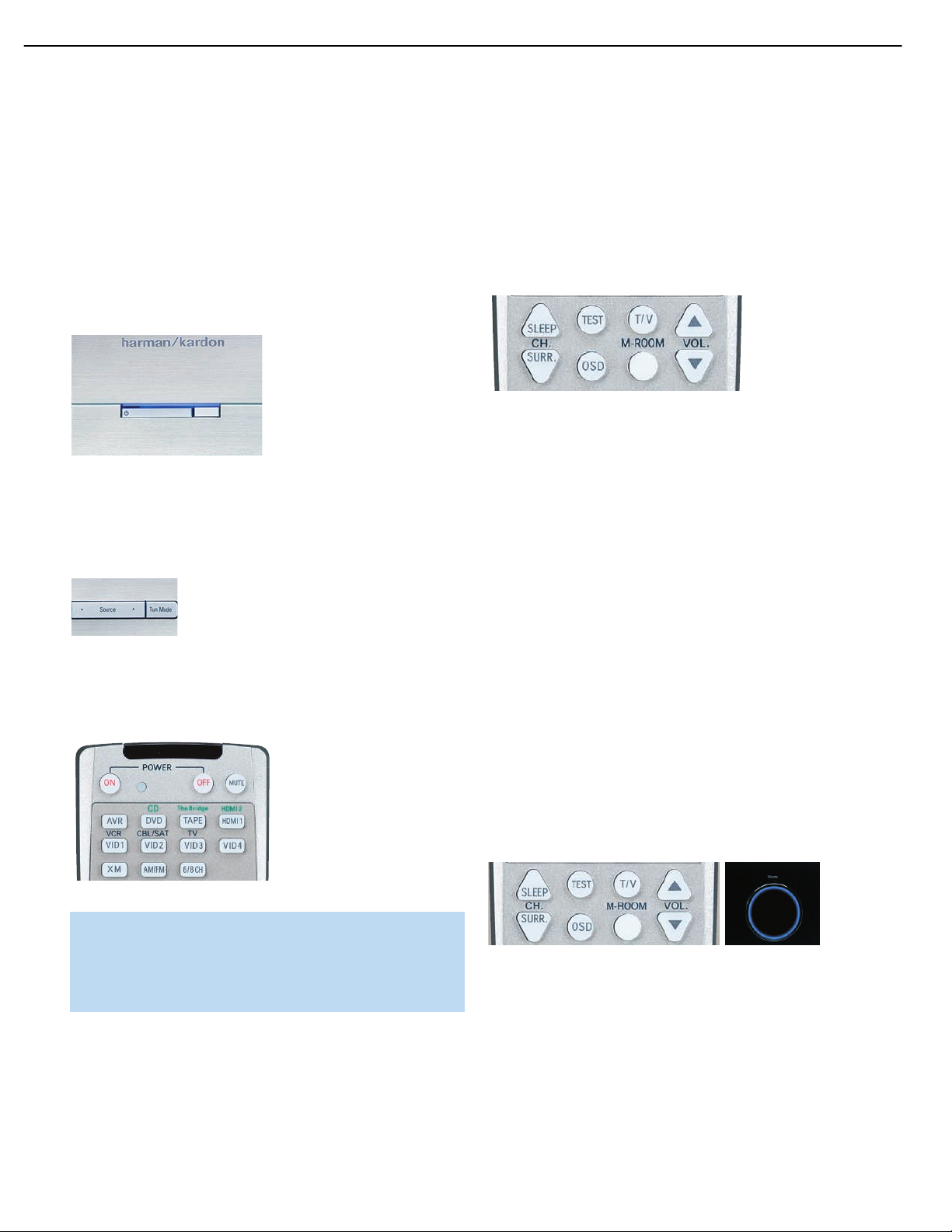
26
AVR247 harman/kardon
OPERATION
Now that you have installed your system components and completed at
least a basic configuration of your receiver, you are ready to begin
enjoying your home theater system.
Turning On the AVR 247
Gently press the Master Power Switch until the word OFF is no longer visible.The Power Indicator above the two power switches should light up in
amber. This indicates that the AVR is in Standby mode and is ready to be
turned on. Normally, you may leave the Master Power Switch in the ON
position, even when the receiver is not being used. See Figure 58.
Figure 58 – Power Switches
There are several ways in which the AVR 247 may be turned on:
a) Press the Standby/On Switch on the front panel. See Figure 58.
b) Press the Source Select Button on the front panel. See Figure 59.
Sleep Timer
You may program the AVR to play for up to 90 minutes and then turn
off automatically using the sleep timer.
Press the Sleep Button on the remote, and the time until turn-off will be
displayed. See Figure 61. Each additional press of the Sleep Button will
reduce the time until turn-off by 10 minutes, until the OFF setting is
reached, which disables the sleep timer.
Figure 61 – Sleep Button
When the sleep timer has been set, the front-panel display will automatically dim to half-brightness. If you press any button on the remote or
front panel, the display will return to full-brightness. The display will dim
again several seconds after your last command.
If you press the Sleep Button after the timer has been set, the remaining
time until turn-off will be displayed. You may press the Sleep Button to
change the time until turn-off. Pressing and holding the Sleep Button will
disable the sleep timer, and the SLEEP OFF message will appear.
Figure 59 – Source Select Button
c) Using the remote, press any one of these buttons: AVR, DVD/CD,
TAPE/The Bridge, HDMI 1/HDMI 2, VID1, VID2,VID3, VID4, XM,
AM/FM, 6/8CH. See Figure 60.
Figure 60 – AVR and Input Selectors
NOTE: Any time you press one of the remote’s Input Selectors
(i.e., DVD/CD, TAPE/The Bridge, XM, VID1,VID2, VID3, VID4 or
HDMI 1/HDMI 2), the remote will switch modes so that it will
only operate that device.To control the receiver, press the AVR
Button to return the remote to AVR mode.
To turn the receiver off, press either the Standby/On Switch on the front
panel, or press the AVR Button and the OFF Button on the remote.
Unless the receiver will not be used for an extended period of time (for
example, if you will be on vacation), it is not necessary to turn off the
Master Power Switch. When the Master Power Switch is turned off, any
settings you have programmed, including system configuration and
preset radio stations, will be preserved for up to four weeks.
Volume Control
The volume may be adjusted either by turning the knob on the front
panel (clockwise to increase volume or counterclockwise to decrease
volume), or by pressing the Volume Control Buttons on the remote.
See Figure 62. The volume is displayed as a negative number of
decibels (dB) below the 0dB reference point, and may be changed
in 0.5dB increments.
Unlike the volume controls on some other products, 0dB is the maximum
volume for the AVR 247. Although it’s physically possible to turn the
volume to a higher level, doing so may damage your hearing and your
speakers. For certain more dynamic audio materials, even 0dB may be
too high, allowing for damage to equipment.
Figure 62 – Volume Controls
The AVR 247 is designed to reproduce audio with a minimum amount
of distortion, which may lead you to think that your hearing and the
equipment can handle higher volumes.We urge caution with regard to
volume levels.
Mute Function
To temporarily mute all speakers and the headphones, press the Mute
Button on the remote. See Figure 63. Any recording in progress will not
be affected. The MUTE message will flash in the display as a reminder.
Page 27
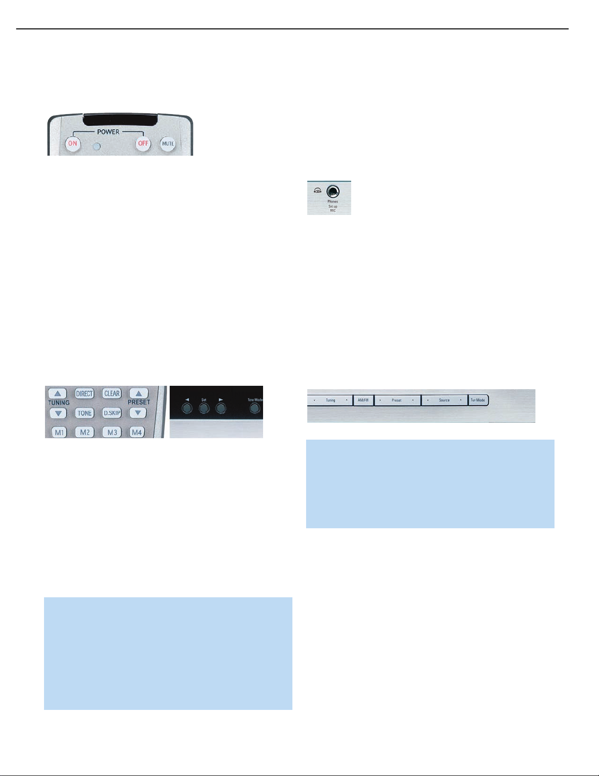
27
AVR247 harman/kardon
OPERATION
To restore normal audio, either press the Mute Button again, or adjust
the volume.Turning off the AVR will also end muting.
Figure 63 – Mute Button
Tone Controls
You may boost or cut either the treble or the bass frequencies by
up to 10dB.
Using the front-panel controls or the remote, press the Tone Mode
Button once. See Figure 64. This will indicate whether the tone controls
are in or out of the circuitry. If you wish to return the tone controls to 0,
‹/›
or “flat” response, press the
the TONE OUT message appears, which preserves any changes you
have made to the bass or treble settings for later use.To reactivate your
changes, the tone control must again be set to TONE IN.
With the TONE IN message displayed, press the Tone Mode Button
repeatedly to access TREBLE MODE and BASS MODE. Use the
Buttons (⁄/¤on the remote) to change the treble or bass settings,
as desired. The display will return to normal a few seconds after your
last command.
Buttons (⁄/¤on the remote) until
‹/›
Headphones
Plug the 1/4" plug on a pair of headphones into the headphone jack
on the front of the receiver for private listening. See Figure 65. The
first time you use the headphones, the DOLBY H:BP message will be
displayed, indicating that Dolby Headphone surround processing is
in the bypass mode, which delivers a conventional 2-channel signal
to the headphones.
Figure 65 – Headphone Jack
Press the Surround Select Button on the front panel, or the Dolby
Button on the remote, to switch to Dolby Headphone virtual surround
processing, indicated by the DOLBY H:DH message. Dolby Headphone
delivers an enhanced sound field that emulates a 5.1-channel speaker
system. No other surround modes are available for the headphones.
Source Selection
Press the front-panel Source Select Button to scroll through the
sources.The left side of the button scrolls down the list that appears in
the display; the right side scrolls upward. For direct access to the tuner,
press the Tuner Band Button, which switches to the last-used band and
frequency. See Figure 66.
Figure 64 – Tone Button
You may alternatively adjust the tone controls using the full-OSD menu
system. Press the OSD Button on the remote to view the menu system.
The Input Setup tab will be highlighted. Press the Set Button to activate
the Input Setup menu. If you wish to make any changes to the TONE,
⁄/¤
BASS or TREBLE settings, use the
the cursor to the line you wish to change, and press the Set Button.
Once you have changed the setting using the
Set Button to enter the new setting. When you have finished, either wait
until the display times out and disappears, press the OSD Button to clear
the display, or move the cursor to the menu tabs on the left side of the
screen line if you wish to make other changes using the menu system.
NOTE: The AVR 247 does not have a conventional balance
control. The EzSet/EQ process compensates for any characteristics of your room or speakers, and we recommend that you
leave the settings as they are after EzSet/EQ has been run.
However, you may manually adjust the levels of the left and
right channels – decreasing one and increasing the other
by the same amount – using the Channel Adjust submenu,
as described in the Advanced Functions section. This achieves
the same effect as a balance control.
keys on the remote to move
‹/›
Buttons, press the
Figure 66 – Source Select and Tuner Band Buttons
NOTE: The Bridge/DMP, HDMI and HDMI 2 sources have no
icon in the Source Indicators display. When selected, the appropriate indication will appear in the Message Display’s upper line.
One of two messages will scroll on the right side to indicate
whether The Bridge is unplugged or connected. If you have
retitled this source, then only the new name will appear in the
upper line.
For direct access to any source, press its Input Selector on the remote
(see Figure 60). Since the AVR 247 allows for more source input
devices than the remote has buttons for, some sources are required
to share buttons.These are the DVD and CD sources, the Tape and
The Bridge sources, and the HDMI 1 and HDMI 2 sources. The first press
of any of these three Input Selectors will select the source whose name
appears on the button (i.e., DVD, Tape or HDMI 1), as indicated by the
button lighting up in red. Press that Input Selector again quickly to select
the source whose name appears above the button (i.e., CD,The Bridge
or HDMI 2), and the selector will light in green to indicate that you have
selected the source whose name is printed above the button.
The AVR 247 will switch to the audio and video inputs assigned to the
source. If you selected a surround mode for the source, the AVR 247
will switch to that mode.
Page 28
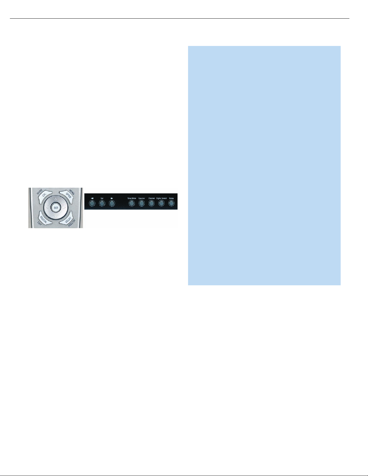
28
AVR247 harman/kardon
OPERATION
The source name will appear in the upper line of the front-panel display.
If you retitled the source, only the new title will appear. Otherwise, the
audio input assigned to the source (analog or one of the digital audio
inputs) will also appear. The surround mode will be displayed on the
lower line.The same information will also appear on screen in the
semi-OSD, unless you have set the semi-OSD to OFF in the System
Setup menu, as described in the Advanced Functions section.
Audio Input Selection
The AVR 247 is programmed at the factory to use the analog audio
inputs for each source (except for the DVD, Video 2, HDMI 1 and
HDMI 2 sources; see Table 6). To assign a digital audio input to a
source (if you have not done so using the Input Setup menu during
Initial Setup), press the Digital Button on the remote or front panel. The
current audio input selection will flash in the display, and you may press
⁄/¤
the
audio inputs.When the desired input appears, press the Set Button to
select it. See Figure 67.
Figure 67 – Digital Input Selection
If the Auto Poll feature is ON in the Input Setup menu, and if a digital
audio input has been assigned to the source, the AVR 247 will first
check the digital audio input for a signal. If a signal is present, the
AVR 247 will select the digital audio input. If no signal is present,
the AVR 247 will switch to the analog audio inputs for the source.
(or ‹/›on the front panel) Buttons to scroll through the
Video Input Selection
When a source is selected, the AVR 247 switches to a video input
as follows:
NOTES:
• Due to copy-protection restrictions, there is no output at the
Component Video Monitor Outputs for copy-protected sources.
• High-resolution 1080i and 1080p video signals are not available at the HDMI Output, and are downconverted to 720p for
the Component Video Monitor Outputs. If your source outputs
analog high-resolution video, either use the Component Video
Outputs, change the output resolution of your source device
to 720p, or connect your source’s component video outputs
directly to your video display.
• Due to the design of some video displays, analog 480p or
720p component video source signals may produce artifacts
when used with the AVR’s analog video outputs (composite,
S-video or component video). If this occurs, try changing the
Video Mode setting in the INPUT SETUP menu, or connecting
the source device’s video output directly to your video display.
However, for best results, we recommend that you consider
upgrading to an HDMI-capable video display.
• The AVR 247 cannot convert 1080i or 1080p analog video
signals to the HDMI format and downconverts them to 720p for
the Component Video Outputs. This affects users of Microsoft
Xbox 360 systems and some older set-top boxes. If your digital
cable television set-top box outputs 1080i or higher video via
component video outputs and is not equipped with an HDMI
output, contact your cable operator for a replacement. For Xbox
360 or satellite receivers with no HDMI output, change the
settings on your source device so that it outputs only 720p
video through its component video outputs, which the AVR can
convert to the HDMI format. Although you could connect the
source device’s component video outputs directly to your video
display, you would then have to select the correct video input
on the display to match the AVR’s input.
The component video inputs may be reassigned to other source inputs
as needed, depending on the physical connections you made during the
Installation procedure.
The VIDEO IN line of the Input Setup menu indicates which of the video
inputs on the AVR 247 is assigned to each source. As shown in Table 5,
by default the Component Video 1 input is assigned to the DVD source,
the Component Video 2 input is assigned to the Video 1 source, and the
Component Video 3 input is assigned to the Video 2 source. The two
HDMI inputs obtain the video signal from their own inputs, and may not
be reassigned to another video input.
If your iPod is capable of playing still-images and videos, it may be used
as a video source. However, you may reassign the video input for The
Bridge to another device for viewing while listening to audio files stored
on the iPod.
All other sources default to the COMPOSITE setting, meaning that they
may only be used with their composite or S-video inputs.The AVR 247
will transcode the incoming composite or S-video signal and make it
available using the HDMI or Component Video Monitor Outputs, enabling
a single-cable connection to your television.
If a signal is present at the component video input assigned to that
source, it will be selected.
If no signal is present at the component video input, then the S-video or
composite video input for the source will be selected. It is not possible
to reassign the S-video or composite video inputs to other sources.
For audio-only sources, such as the tuner or CD inputs, when no component video signal is present, the last-used video source will be selected.
6-/8-Channel Direct Inputs
If you wish to hear audio through the 6-/8-Channel Direct Inputs together
with video, then connect your multichannel player to the Component
Video 1 Inputs, and connect the player’s 6- or 8-channel analog audio
outputs to the 6-/8-Channel Inputs on the AVR. Assign the component
video inputs you selected to the 6-/8-Channel Input source.The AVR
will automatically select the correct component video and audio inputs
when you select this source.
Page 29
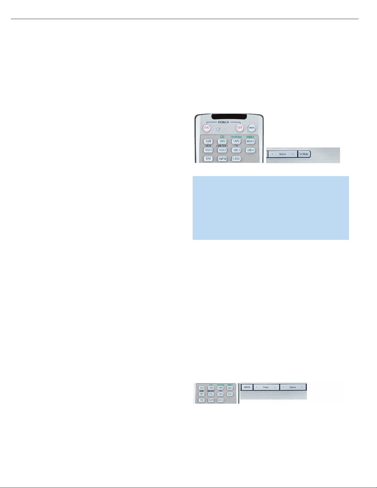
29
AVR247 harman/kardon
OPERATION
If you need to use composite or S-video for your multichannel player,
e.g., if your video display does not have component video inputs, then
use the video inputs for another source. Since the AVR automatically
selects the last-used video inputs for audio sources, first select the
source you connected the video cables to, and then the 6-/8-Channel
Inputs for the audio.
Example 1: You would like to connect a DVD-Audio player to the
AVR 247. You plan on playing a variety of discs using this player,
including conventional DVDs and even CDs as well as multichannel
discs.When playing DVDs and CDs, it is preferable to use a digital audio
connection to obtain the best sound quality and the benefit of any digital
surround formats contained on the DVD. However, when playing DVDAudio discs, you will need to use the 6-/8-channel analog audio
connections. In addition, some of these discs contain video materials.
The player does not have an HDMI output.
We recommend that you connect this player as follows:
a) Connect the player’s coaxial digital audio output to the Coaxial 1 input
on the AVR. This input is assigned by default to the DVD source.
b) Connect the player’s component video outputs to the Component
Video 1 inputs on the AVR, which are assigned by default to the DVD
source. If your video display doesn’t have component video inputs,
then connect the player’s composite or S-video output to the DVD’s
corresponding video input.
When you wish to view a DVD, simply select the HDMI 1 source.
When you wish to play a multichannel disc, first select the analog video
source, e.g., Video 3, to obtain the correct video signal, then select the
6-/8-Channel Inputs to select the audio signal.
To select the 6-/8-Channel Inputs as the source, use either the Source
Selector on the front panel or press the 6/8CH Input Selector on the
remote. See Figure 68.
Figure 68 – 6-/8-Channel Input Selector
NOTE: The 6-/8-Channel Inputs pass the incoming signals
directly to the volume control, without digitizing or processing
them. Therefore, you will need to configure bass management
settings (i.e., speaker size, delay and output level) on your source
device so that they match the settings you programmed using
EzSet/EQ, which may be viewed using the Manual Setup menu
(see Advanced Functions section). Consult the owner’s guide for
your multichannel player for more information.
c) Connect the player’s 6-channel analog audio outputs to the AVR’s
6-/8-Channel Inputs and assign the Component Video 1 inputs to
this source using the Input Setup menu, as described in the Initial
Setup section.
d) Program the player’s remote control codes into the DVD Input
Selector. Note that not all commands will necessarily be available.
When you wish to view a DVD, simply select the DVD source.
When you wish to listen to a DVD-Audio disc and view the menus
and other still images on the disc, first select DVD, and then the
6-/8-Channel Inputs as the source.
Example 2: In this example, your multichannel disc player is equipped
with an HDMI output, but it does not comply with HDMI version 1.1.
Connect it as follows:
a) Connect the player’s HDMI output to the HDMI 1 source input, and
make sure to connect the AVR’s HDMI Output to your video display.
The player will transmit both digital audio (e.g., Dolby Digital or DTS
audio found on a DVD-Video disc) and video via the HDMI connection.
It is not necessary to make a separate digital audio connection.
b) Connect the player’s 6-channel analog audio outputs to the AVR’s
6-/8-Channel Inputs, and connect one of the player’s analog video
outputs to a source input on the AVR (e.g., Component Video 3 or
Video 3).
c) Program the player’s remote control codes into the Input Selector
corresponding to the source you used for the analog video connection,
e.g., Video 3.
The multichannel analog audio connection is not required for DVD-Audio
players compliant with HDMI version 1.1 or better, or HD-DVD and
Blu-ray Disc players that decode the digital audio internally and output
linear PCM signals in digital format. Consult the owner’s guide for your
disc player for more information.
Using the Tuner
The AVR 247’s built-in tuner may be selected in one of three ways
(see Figure 69):
1. Press the Source Selector Button on the front panel repeatedly until
the tuner is selected. The last-used band (AM or FM) will be active.
2. Press the Tuner Band Button (marked AM/FM). Press this button
again to switch bands.This will also enable you to select XM Radio,
which is described separately in the next section.
3. Press the Tuner Input Selector (marked AM/FM) on the remote. Press
this button again to switch bands (AM, FM or XM).
Figure 69 – Tuner Input Selection
Radio stations may be selected in one of four ways (see Figure 70):
1. If you know the frequency number, enter it directly by first pressing
the Direct Button on the remote, and then using the Numeric Keys.
Page 30
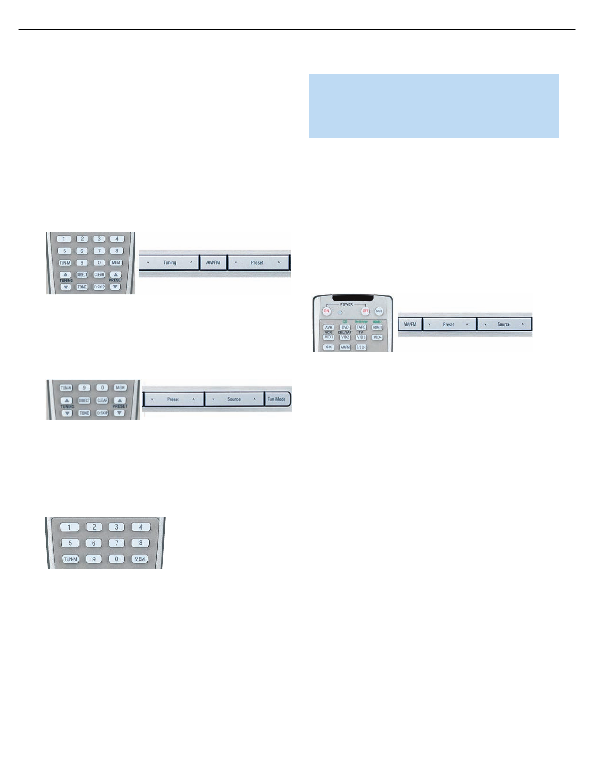
30
AVR247 harman/kardon
OPERATION
2. After you have programmed Preset stations (see below), either enter the
Preset number (1 through 30) using the remote or use the Preset Stations
Buttons (front panel or remote) to scroll through the list of presets.
3. In Auto tuning mode, with each press of the Tuning Buttons (front
panel or remote), the AVR 247 will scan in the chosen direction until
a station with acceptable signal strength is detected. Press the Tuning
Button again to stop scanning.
4. In Manual tuning mode, with each press of the Tuning Buttons, the
AVR 247 will tune the next frequency increment (0.1MHz for FM, or
10kHz for AM) in the selected direction. Press and hold the Tuning
Button for faster scanning.
Figure 70 – Tuning a Station
Press the Tuning Mode Button (TUN-M on the remote) to switch
between Auto and Manual tuning modes. See Figure 71. When an
FM station has been tuned, pressing the Tuning Mode Button will switch
between stereo and mono tuning, which may improve reception of
weaker stations.
NOTE: To listen to XM Radio using the AVR 247, you will need
to purchase an XM antenna module and subscription, and you
will need to activate your module. (Note that XM service is not
available in Alaska or Hawaii.) Visit the XM Radio Web site at
www.xmradio.com for more information.
Plug the module into the XM Antenna Jack on the rear of the AVR 247.
Place the antenna module so that it has a clear view through a southfacing window in order to obtain reception from the XM satellite.
Select XM Radio as the source in one of the following three ways
(see Figure 73):
1. Press the Source Selector button on the front panel repeatedly until
XM Radio is selected. XM will only appear in the Message Display.
2. Press the Tuner Band Button (front-panel or remote) repeatedly until
XM Radio is selected.
3. Press the XM Radio Input Selector on the remote.
Figure 73 – XM Radio Source Selection
You should be able to tune in Channel 1, the Preview Channel, to
confirm that your equipment is ready for activation. There are three
ways to tune an XM Radio channel (see Figure 70):
Figure 71 – Tuning Mode
To store a station in one of the 30 presets (see Figure 72):
1. Tune the desired station.
2. Press the Memory Button on the remote.
3. Use the Numeric Keys to enter the desired preset number.
Figure 72 – Storing a Preset Station
XM Radio Operation
XM Radio is a satellite-delivered service that offers hundreds of program
channels, as well as local traffic and weather information for select cities.
The AVR 247 is “XM Ready,” which means that it is able to receive the
XM service when an optional XM antenna module is connected and the
service activated. As of this writing, the Audiovox
and Play” module for home audio use and the XM Mini-Tuner and
Home Dock (Models CNP-2000 and CNP-2000H) are compatible with
the AVR 247. Additional modules may become available in the future.
Modules produced for automotive, or “mobile,” use are not compatible
with the AVR 247.
®
CNP 1000 “Connect
1. Enter the channel number directly using the Numeric Keys on the
remote. It is not necessary to press the Direct Button first.
2. Press the Tuning Buttons on the front panel or remote to scan
through the channels.Auto tuning mode is not available.
3. The AVR 247 is capable of storing up to 40 XM Radio preset channels.
The presets are divided into five banks, denoted by the letters A
through E, with eight numeric presets per bank. After you have
programmed preset stations (see below), you may select one by
pressing the Set Button repeatedly until PRESET SEARCH appears,
⁄/¤
then using the
Buttons to change the bank (A through E).
Use the Preset Buttons to scan through the eight numeric positions
within a bank.
When you are able to hear Channel 1, you are ready to activate your
module. If you don’t hear Channel 1, make sure the module’s plug is
firmly seated in the XM Antenna jack, and that the module is near a
south-facing window.Try unfolding the module and rotating it to obtain
reception. You may need to purchase an extension cable, available on
the XM Radio site, to ensure that the module is near the window.
Tune to Channel 0 for a display of your antenna module’s Radio ID
number, required for activation.
The current channel number and preset location will appear in the upper
line of the Message Display, and the channel’s name will appear in the
lower line.Three signal-strength bars will appear to the right of the
41
Page 31

The
Bridge
TM
31
AVR247 harman/kardon
OPERATION
channel number and preset location. Press the Tuning Mode Button
repeatedly to display the category, current artist or song title.
For traffic and weather channels, the current city’s name will appear
instead of the channel name, and pressing the Tuning Mode Button
repeatedly will display the local weather and temperature.
Press the Set Button to search all channels. Press it again to search by
⁄/¤
category, using the
Buttons to change the category. Press the
Set Button again to tune the lowest-numbered station available in that
category, or without using the arrow keys, press the Set Button to
⁄/¤
change the preset bank, using the
Buttons to change the bank
letter. Press the Set Button again to return to the all-channel search.
To store a channel in one of the 40 preset locations:
1. Press the Set Button repeatedly until PRESET SEARCH appears, then
⁄/¤
use the
Buttons until the desired bank of presets (A through E)
appears in the upper line of the Message Display.
2. Press the Memory Button, and a line will appear next to the preset
bank letter.
3. Use the Numeric Keys to enter the preset location (1 through 8) you
wish to store the channel in.
Recording
audio/video system, operate the iPod using the AVR remote or the
AVR’s front-panel controls, view navigation messages on the AVR’s
front panel or a connected video display, and charge the iPod.
Either press the front-panel Source Selector repeatedly until the message “DMP/The Bridge is CONNECTED” scrolls across the front panel
and semi-OSD displays, or press the DMP Button on the remote to
select The Bridge as the input source.
When an iPod is docked in The Bridge, the screen shown in Figure 74
will appear on a video display connected to the AVR. Navigate The
‹/›
Bridge’s screens by using the
pressing the Set Button to select the line.The
‹
and the
Button scrolls up. Press the Menu Button to return to the
Buttons to highlight a line and
›
Button scrolls down,
previous level of The Bridge’s menu system. Remember to set the
remote in The Bridge device mode by pressing the Tape/The Bridge
button. If it lights in red, press it again quickly so that it lights in green,
indicating it is in The Bridge mode.
Two-channel analog and digital audio signals, as well as composite
and S-video signals, are normally available at the appropriate recording
outputs.Thus, to make a recording, you need only make sure to connect your audio or video recorder to the appropriate output jacks, as
described in the Installation section, insert blank media and make sure
the recorder is turned on and recording while the source is playing.
NOTES:
1. Analog audio signals are not converted to digital form, and
digital audio signals are not converted to analog audio form.
However, you may record a coaxial or optical digital audio
source using either type of digital audio output.
2. Only PCM digital audio signals are available for recording.
Proprietary formats such as Dolby Digital and DTS may not
be recorded using the digital audio connections, although if
the source is connected to the AVR using the analog audio
connections, an analog recording may be made.
3. HDMI and component video sources are not available for
recording.
4. Please make certain that you are aware of any copyright
restrictions on any material you record. Unauthorized duplication of copyrighted materials is prohibited by federal law.
Using
Figure 74 – The Bridge: Main Menu Screen
MUSIC: This line allows you to navigate the audio materials stored on
your iPod.
PHOTOS/VIDEOS: Selecting this item allows you to play still images or
videos stored on the iPod. The screen shown in Figure 75 will appear,
directing you to operate the iPod’s own controls directly to play images
and videos.You may use the AVR 247 remote instead of the iPod’s
controls to navigate it, but the iPod’s menu will only be displayed on
its internal screen. Visual materials will be displayed on a video display
connected to the AVR.
NOTE: After selecting video/photo viewing, the AVR may remain
in iPod Manual Mode, even after undocking the iPod or switching to another source input and back again. To return to normal
operation, with the AVR remote in The Bridge mode, press and
hold the Menu Button.
The Bridge is an optional dock that may be used with a compatible
iPod (not included). When The Bridge is connected to its proprietary
input on the AVR 247 and the iPod is docked, you may enjoy the audio,
video and still-image materials on your iPod through your high-quality
Figure 75 – The Bridge: Playing Images and Videos
Page 32

32
AVR247 harman/kardon
OPERATION
SETTINGS: This line accesses the Settings menu, shown in Figure 76.
The items in this menu enable you to use the Shuffle and Repeat
functions on the iPod. You may also set the Resume function, which
resumes play of a selection from the point at which it was stopped,
Figure 76 – The Bridge: Settings Menu Screen
NOTE: iTunes allows you to set certain selections to always or
never remember playback position, or to be skipped in Shuffle
mode.The AVR 247’s settings cannot override these iTunes settings.
Figure 77 – Using The Bridge (Remote)
NOTES:
• The Play and Pause functions are not available unless content
has been selected for playback by navigating the menu system.
• For the Search function, press and hold the indicated button.
Pressing the Previous Track Button once skips to the beginning
of the current track. Press the Previous Track Button
twice to
skip to the beginning of the previous track.
While a selection is playing, the song title, artist and album name, if available
on the iPod, will scroll across the upper line in the front panel Message
Display. The lower line will display the elapsed time of the track on the left,
the play mode icon, and the time remaining on the right.
In addition, if a video display is connected to the AVR 247, a screen will
appear briefly to display information about the iPod’s status and the track.
The top line will display the play mode icon, with the phrase “Now Playing”
appearing to the right to indicate that you are viewing the status of the
current track. Below that the AVR displays the total number of tracks in the
current play list on the right (one of the play lists includes all materials on
the iPod) with the number of the current track on the left. The song title,
artist and album are displayed. At the bottom of the screen is a graphic bar
indicating the current play position within the track, with the elapsed and
remaining times appearing below the bar.
After a period of time the screen may disappear from view.The length of
time is set using the Full-OSD Time Out setting in the System Settings
menu (described in the Advanced Functions section). You may restore the
Now Playing screen to view by pressing either of the
‹/›
Buttons, and
you may then navigate the menus as explained above.
Figure 78 – Using The Bridge (Front Panel)
Table 7 summarizes the controls available when The Bridge is in use.
See also Figures 77 and 78.
Table 7 – Using The Bridge
iPod Function Remote Control Key Front-Panel Button
Play Play (›) Tuner Mode
Pause Pause (II) Tuner Mode
Menu Menu (Spkr) Tuner Band (AM/FM)
Select Set Set
Scroll Forward Left Arrow (‹) Preset Down
Scroll Reverse Right Arrow (›) Preset Up
Forward Search/Next Track Forward/Next (››) Tuning Up
Reverse Search/Previous Track Reverse/Previous (
‹‹) Tuning Down
NOTE: It is strongly recommended that you use a screen saver
built into your video display to avoid possible damage from “burn-in”
that may occur with plasma and many CRT displays when a still
image, such as a menu screen, remains on display for an extended
period of time.
NOTES ON VIDEO PLAYBACK:
• Before attempting to play videos stored on your iPod, check the
Video Settings menu on the iPod and make sure that the TV Out
setting is set to On. The TV Signal setting should be NTSC to
match the capabilities of your video display. Set Widescreen to On
or Off, depending on the aspect ratio of your video display. If your
selection was playing and paused at the time you changed the TV
Out setting, the iPod may require you to navigate its menu system
and reselect the video for the new TV Out setting to take effect.
Resuming play from the Now Playing function may not reflect the
change to the TV Out setting. This is a function of the iPod, not
the AVR 247.
• In Video mode, the iPod’s menus will not be visible on your video
display, although you may view them on the iPod’s screen. You
may operate the iPod using the AVR remote, as long as it is in
The Bridge device mode.
• You may view the AVR’s on-screen displays while The Bridge is
in use, just as you would with any other video source.
Page 33

33
AVR247 harman/kardon
OPERATION
• The MP4 and H.264 video formats often used for videos to
be played on the iPod are intended for optimal performance on
the iPod’s small screen. Playback on larger displays may have
different results.
Selecting a Surround Mode
Surround mode selection can be as simple or sophisticated as your
individual system and tastes. Feel free to experiment with the many
available surround modes on the AVR 247, and you may find a few that
become your favorites for certain sources or program types.Although
more detailed information on surround modes may be found in the
Advanced Functions section, it is easy to select any of the modes
available at a given time:
To select a surround mode using the front-panel controls, press the
Surround Mode Button repeatedly until the desired group of modes is
selected: Logic 7, Dolby, DTS, DSP or Stereo. Then press the Surround
Select Button repeatedly to select the desired mode within the group.
See Figure 79.
To select a surround mode using the full-OSD menu system, press the
⁄/¤
OSD Button to display the menu system. Use the
Buttons to
highlight the Surround tab, and press the Set Button to access the
Surround Setup menu, as shown in Figure 81. With the Surround Mode
highlighted, press the Set Button to change the surround mode group.
‹/›
Use the
Buttons to scroll through the options, and press the
Set Button when the desired mode group appears. Navigate to the
Mode line and follow the same procedure to select an individual mode.
As explained in the Advanced Functions section, there are also some
additional settings that may be made.
Figure 81 – Surround Setup Menu Screen
You are now ready to enjoy the best in home theater entertainment with
your AVR 247. As you become more familiar with the receiver, you may
wish to explore some of its advanced functions, which are described in
the following section.
Figure 79 – Select a Surround Mode (Front Panel)
To select a surround mode using the remote control, locate the button
dedicated to the desired group of modes: Logic 7, Dolby Sur, DTS Sur,
DTS Neo:6, Surr (DSP) or Stereo. Press that button repeatedly to select
the desired mode. See Figure 80.
Figure 80 – Select a Surround Mode (Remote)
Page 34

34
AVR247 harman/kardon
TROUBLESHOOTING GUIDE
SYMPTOM CAUSE SOLUTION
Unit does not function when Main • No AC Power • Make certain AC power cord is plugged into
Power Switch is pushed a live outlet
• Check to see whether outlet is switch-controlled
Display lights, but no sound • Intermittent input connections • Make certain that all input and speaker connections
or picture are secure
Mute is on • Press Mute Button
•
• Volume control is down • Turn up volume control
No sound from any speaker; • Amplifier is in protection mode • Check speaker wire connections for shorts at receiver and
light around power switch is red due to possible short speaker ends
• Amplifier is in protection mode • Contact your local Harman Kardon service center
due to internal problems
No sound from surround or • Incorrect surround mode • Select a mode other than Stereo
center speakers • Input is monaural • There is no surround information from mono sources
• Incorrect configuration • Check speaker mode configuration
• Stereo or Mono program material • The surround decoder may not create center- or rear-channel
information from nonencoded programs
Unit does not respond to • Weak batteries in remote • Change remote batteries
remote commands • Wrong device selected • Press the AVR selector
• Remote sensor is obscured • Make certain front-panel sensor is in line of sight of remote
or connect an optional remote sensor
Intermittent buzzing in tuner • Local interference • Move unit or antenna away from computers, fluorescent
lights, motors or other electrical appliances
Letters flash in the channel indicator • Digital audio feed paused • Resume play for DVD
display and digital audio stops • Check that the correct digital input is selected
Surround Back Speaker settings • Multiroom system has been turned on, • Use the OSD menu system to access the Multiroom Setup
cannot be accessed, and test tone and the surround back channels menu and turn off the multiroom system.
does not play through Surround were reassigned to multiroom operation
Back Speakers
The XM Preview Channel (001) • XM antenna is not plugged in • Make sure you are using a home audio XM antenna module
is silent designed for use with XM Ready home audio equipment,
and that the module is plugged into the XM Radio Jack
on the rear panel of the receiver.
• XM antenna is not located in such • The XM Antenna module needs to be placed with an
a way as to enable reception unobstructed view of the southern sky, or within range of an
XM terrestrial repeater. If necessary, purchase an extension
cable from your XM Radio dealer.
Unable to activate Program mode • Input Selector not held for at least • The selector will light as you initially press it, and go dark as you
on remote 3 seconds hold it down. Wait at least 3 seconds for the selector to light
up again, and the Program LED will flash.
Unable to assign a device to • Invalid device assignment attempted • Only the DVD, VCR (includes DVR), cable or satellite (CBL/SAT
HDMI 1 or 2 selectors selector) devices may be assigned to the HDMI 1 or 2 selectors.
Remote behaves erratically • Buttons are pressed too hard • Always press remote control buttons as gently as possible.
Additional information on troubleshooting possible problems with your AVR 247, or installation-related issues, may be found in the list of “Frequently
Asked Questions”, which is located in the Product Support section of our Web site at www.harmankardon.com.
Page 35

35
AVR247 harman/kardon
Erasing Macros
It isn’t possible to “edit” a command within a macro. However, you may erase the macro
as follows:
1. Simultaneously press and hold the Mute Button and the Macro Button
containing the macro until the LED flashes.
2. Press the Surround Button to erase the macro.
Resetting the Remote
To reset the remote to its factory defaults, simultaneously press and hold any Input
Selector and the “0” Numeric Key. When the Program LED flashes in amber, enter the
code “333”. When the green LED goes out, the remote will have been fully reset.
Processor Reset
There may be instances when you wish to fully reset the AVR 247 to its factory defaults,
or the unit may behave erratically after a power surge. To correct erratic behavior, first
try turning the Master Power Switch off and unplugging the AC Power Cord for at least 3
minutes. Plug the cord back in and turn the receiver back on. If this doesn’t help, try a
system reset. NOTE: A system reset erases all user configurations, including
speaker and level settings and tuner presets. After a reset, you will need to re-enter all of
these settings. To reset the AVR 247, place the receiver in Standby mode (press the
front-panel Standby/On Switch so that the Power Indicator turns amber). Then press
and hold the front-panel Tone Mode Button for at least 5 seconds until the RESET
message appears in the display. If the receiver still does not function correctly after a
processor reset, contact an authorized Harman Kardon service center for assistance.
Service centers may be located by visiting our Web site at www.harmankardon.com.
Memory
If the AVR 247 is unplugged or experiences a power outage, it will retain user settings
for up to four weeks.
Page 36

DISASSEMBLY
36
AVR247 harman/kardon
AVR247
1. Removing the Top Cabinet
Remove the Screws
6
4
5
3. Removing the Rear Panel
13
1
~
10
9
11
7
8
12
13
3
1
2
Remove the Screws
10
11
12
13
14
15
16
26
27
9
7 6 5 4
8
28 30 31
34
1
~
22
23
24 25
29
3
2
32 33
18
17
19
1
34
20 21
4. Removing the Main PCB
1 7
Remove the Screws
~
2. Removing the Front Panel
1 9
9
8
7
6
5
4
Remove the Screws
1
2
3
~
1
5
2
6
3
4
7
Page 37

37
AVR247 harman/kardon
AVR247 DIS ASSEMBLY PROCEDURE
1 TOP-CABINET(21) REMOVAL
Remove 13 screws (S1,S7) and t hen r em ov e the Top-cabinet .
2 FRONT PANEL ASS’Y REMOVAL
1. Remove the Top-cabinet, r eferring to the previous step 1.
2. Disconnect the c ar d c able between connector (CN72-17p) on t he Fip PCB (37-1) and connector (CN72) on the Input
PCB (39-1).
3. Disconnect the lead wir e (BN81-8P) on the Fip PCB (37-1) from connect or (CN81) on the Trans PCB (40-4).
4. Disconnect the lead wir e (BN22-6P) on the Phone PCB (37-5) f r om connec tor (CN22) on the Input PCB (39-1).
5. Disconnect the lead wir e (BN18-5P) on the Phone PCB (37-5) f r om connec tor (CN18) on the Input PCB (39-1).
6. Disconnect the lead wir e (BN10-4P) on the Volume PCB (37-6) from connector (CN10) on the Input PCB (39-1).
7. Disconnect the lead wir e (BN41-6P) on the Volume PCB (37-6) from connector (CN41) on the Video PCB (41).
8. Disconnect the lead wir e (BN90-2P) on the Main PCB (38-1) from c onnec tor (CN86) on the Moms PCB (37-4).
9. Remove 1 screw (S10) and then l ead wir e ( JW82-1P,JW83-1P) on the Phone PCB (37-5).
10. Remove 1 screw (S10) and then lead wire ( JW84-1P) on the Volume PCB (37-3).
11. Remove 10 screws (S1) and then remove the Front Panel ASS’Y.
3 Volume PCB (37-6) REMOVAL
1. Remove the Top-cabinet, r eferring to the previous step 1.
2. Remove the Front Panel ASS’Y, r eferring to the previous step 2.
3. Pull out the Volume Knob ASS’Y.
4. Disconnect connector (CN84) on the Volume PCB (37-6) from the lead wire (BN84-5P) on the Fi p PCB (37- 1).
5. Disconnect the lead wir e (BN92-5P)on the Volume PCB (37-6) from connector (CN92) on the Phone PCB (37-5).
6. Remove 8 screws (S2,S14), and then remove the Volume PCB (37-6).
4 PHONE PCB (37-5) REMOVAL
1. Remove the Top-cabinet, r eferring to the previous step 1.
2. Remove the Front Panel ASS’Y, r eferring to the previous step 2.
3. Disconnect connector (CN92) on the Phone PCB (37- 5) fr om the lead wir e ( B N92-5P) on the Volume PCB (37-6).
4. Disconnect connector (CN85) on the Phone PCB (37- 5) fr om the lead wir e ( B N85-3P) on the Fip PCB (37-1).
5. Remove 2 screws (S2) and then rem ove the Phone PCB (37-5).
5 POWER LED PCB (37-3) REMOVAL
1. Remove the Top-cabinet, r eferring to the previous step 1.
2. Remove the Front Panel ASS’Y, r eferring to the previous step 2.
3. Disconnect connector (CN88) on the Power Led PCB (37-3) from the lead wire (BN88-4P) on the Fip PCB (37-1) .
4. Remove 2 screws (S2) and then rem ove the Power LED PCB (37-3).
6 FIP PCB (37-1) REMOVAL
1. Remove the Top-cabinet, r eferring to the previous step 1.
2. Remove the Front Panel ASS’Y, r eferring to the previous step 2.
3. Disconnect the lead wir e (BN84-5P) on the Fip PCB (37-1) from connect or (CN84) on the Volume PCB (37-6).
4. Disconnect the lead wir e (BN85-3P) on the Fip PCB (37-1) fr om connect or ( CN85) on the Phone P CB (37-5) .
Page 38

38
AVR247 harman/kardon
5. Disconnect the lead wir e (BN88-4P) on the Fip PCB (37-1) from connect or (CN88) on the Power Led PCB (37-3).
6. Disconnect the c onnec tor (CN89) on the Fip PCB (37-1) from l ead wire (BN89-4P) on the Key PCB (37-2).
7. Remove 3 screws (S2) and then rem ove the Guide PCB (37-8) & the Fip PCB (37-1).
7 KEY PCB (37-2) REMOVAL
1. Remove the Top-cabinet, r eferring to the previous step 1.
2. Remove the Front Panel ASS’Y, r eferring to the previous step 2.
3. Remove the Fip PCB (37- 1) , referring to the previous step 6.
4. Remove 10 screws (S2) and then remove the Key PCB (37-2).
8 T UNE R MODULE ( 44) REMOVAL
1. Remove the Top-cabinet, r eferring to the previous step 1.
2. Disconnect the car d c able between connector (CON1-13P) on t he Tuner module (44) and connector (CN13) on the
Input PCB (39-1).
3. Remove 2 screws (S8) and then remove the Tuner Module (44).
9 HUDSON PCB (42) REMOVAL
1. Remove the Top-cabinet, r eferring to the previous step 1.
2. Disconnect connect or ( CN80) on the HUDSON PCB (42) from the lead wire (BN80-3P) on the RS232 P CB (37-7).
3. Remove 3 screws (S15).
4. Disconnect the board to boar d c onnec tor between and connector (CN81-44P ) on the HUDSON PCB (42) and
connector (BN81- 44P ) on VIDE O PCB (41) and then remove the HUDSON PCB (42).
10 VIDEO PCB (41) REMOVAL
1. Remove the Top-cabinet, r eferring to the previous step 1.
2. Remove the Hudson PCB (42), r eferring to the previous step 9.
3. Disconnect the car d c able between connector (BN14-17p) on the Video PCB (41) and connector (CN14) on the I nput
PCB (39-1).
4. Disconnect connect or ( CN43) on the Video PCB (41) from the lead wire (BN43-3P) on the Regulator PCB (A)(40-2).
5. Disconnect connect or ( CN41) on the Video PCB (41) from the lead wire (BN41-6P) on the Volume PCB (37-6).
6. Disconnect the car d c able between connector (CN42) on the Video PCB (41) and connec tor (BN44-7P) on the iPod
PCB (39-2).
7. Disconnect the car d c able between connector (BN15-15P) on the Video PCB (41)and connector (CN15-15P ) on the
INPUT PCB (39-1).
8. Remove 6 screws (S8) and then remove the Video PCB (41).
11 iPod PCB (39-2) REMOVAL
1. Remove the Top-cabinet, r eferring to the previous step 1.
2. Remove the Hudson PCB (42), r eferring to the previous step 9.
3. Remove the Video PCB (41), ref er ri ng to t he pr ev ious step10
4. Disconnect the car d c able between connector (BN19-15P) on the the iPod PCB (39-2) and connector ( CN19) on the
Input PCB (39-1).
5. Disconnect the car d c able between connector (BN44-7P) on the iPod PCB (39-2) and connector (CN42) on the Video
PCB (41).
6. Disconnect the car d c able between connector (CN47-7P) on the iPod PCB (39-2) and connector (CN47) on the
RS232 PCB (37-7).
7. Disconnect the board to board connector between and connector ( CN23) on the XM PCB (39-4) and connector
Page 39

39
AVR247 harman/kardon
(BN17-12P) on the iP od P CB (39-2) .
8. Remove 2 screws (S13) and then remove the iPod PCB (39-2).
12 XM P CB ( 39- 4) REMOVAL
1. Remove the Top-cabinet, r eferring to the previous step 1.
2. Remove the Hudson PCB (42), r eferring to the previous step 9.
3. Remove the Video PCB (41), ref er ri ng to t he pr ev ious step 10
4. Disconnect the car d c able between connector (BN21-7P) on XM PCB (39-4) and connector (CN21) on the input P CB
(39-1).
5. Disconnect the lead wire ( BN85-2P) on the XM PCB (39-4) from connect or (CN85) on the Regulator PCB (A)(40-2).
6. Disconnect the board to board connector between and connector ( CN23) on the XM PCB (39-4) and connector
(BN17-12P) on the iP od P CB (39-2) .
7. Remove 1 screw (S15) and then remove the XM PCB (39-4).
13 RS232 P CB ( 37- 7) RE MOVAL
1. Remove the Top-cabinet, r eferring to the previous step1.
2. Remove the Hudson PCB (42), r eferring to the previous step9.
3. Remove the Video PCB (41), ref er ri ng to t he pr ev ious step10.
4. Disconnect the car d c able between connector (CN47-7P) on the iPod PCB (39-2) and connector (CN47) on the
RS232 PCB (37-7).
5. Remove 2 screws and then remove the RS232 P CB (37-7) .
14 INPUT PCB (39-1) REMOVAL
1. Remove the Top-cabinet, r eferring to the previous step 1.
2. Remove the Tuner module (44), referring to the previous step 8.
3. Remove the Hudson PCB (42), r eferring to the previous step 9.
4. Remove the Video PCB (41), ref er ri ng to t he pr ev ious step 10.
5. Disconnect connect or ( CN20) on the Input PCB (39-1) from the lead wire (BN20-5P) on the Regulator PCB (B)(40-5).
6. Disconnect connect or ( CN22) on the Input PCB (39-1) from the lead wire ( B N22- 6P ) on the P hone P CB (37-5).
7. Disconnect connect or ( CN18) on the Input PCB (39-1) from the lead wire ( B N18- 5P ) on the P hone P CB (37-5)
8. Disconnect connect or ( CN10) on the Input PCB (39-1) from the lead wire (BN10-4P) on the Volume PCB (37-6).
9. Disconnect the car d c able between connector (CN14) on the Input PCB (39- 1) and connect or (BN14-17P) on the
Video PCB (41).
10. Disconnect the card cable between connector (CN19) on the Input PCB (39- 1) and connect or (BN19-15P) on the IPod PCB (39-2).
11. Disconnect the card cable between connector (CN21) on the input PCB (39-1) and c onnec tor (BN21-7P) on XM PCB
(43).
12. Disconnect the card cable between connector (CN12-21p) on t he Input PCB (39-1) and connector ( CN12- 21p) ) on the
main PCB (38-1)
13. Disconnect the card cable between connector (CN11-17p) on the Input PCB (39-1) and connector (CN11) on the main
PCB (38-1)
14. Disconnect the card cable between connector (CN72) on the Input PCB (39- 1) and connect or (CN72-17p) on the Fip
PCB (37-1)
15. Remove 11 screws (S8,S15) and then remove the Input PCB (39-1).
15 POWER TRANS (36) & POWER PCB ASS’Y(40) REMOVAL
1. Remove the Top-cabinet, r eferring to the previous step 1.
2. Disconnect lead wire of the P ower Trans (36) from connector (CN91- 3P ) on the Main PCB (38-1)
Page 40

40
AVR247 harman/kardon
3. Disconnect connect or ( CN19-3P,CN20-4P) on TRANS PCB (40-3) from the lead wire (BN19-3P,BN20-4P) on the
Main PCB (38-1).
4. Disconnect the lead wire ( BN96-8P) on the Power PCB (40-4) f r om connec tor (CN96) on the Regulator PCB (B)(40-5) .
5. Disconnect the lead wire ( BN99-8P) on the Power PCB (40-4) f r om connec tor (CN99) on the Regulator PCB (A)(40-2) .
6. Disconnect connect or ( CN81) on the Trans PCB (40- 4) from the lead wire (BN81-8P) on t he Fip PCB (37- 1) .
7. Remove 4 Trans screws (S9) and then remove the Power Trans (36) & Power PCB ASS’Y(40) REMOVAL .
16 REMOTE PCB ASS’Y(40-7) REMOVAL
1. Remove the Top-cabinet, r eferring to the previous step 1.
2. Disconnect connect or ( CN88) on the remote PCB (40-7) from the lead wire (BN88-6P) on the Main P CB (38-1)
3. Remove 3screws (S13) and then remove the Remote PCB ASS’Y(40-7).
17 MAIN PCB ASS’Y(38-1) REMOVAL
1. Remove the Top-cabinet, r eferring to the previous step 1.
2. Remove the Tuner module (44), referring to the previous step 8.
3. Remove the Hudson PCB (42), r eferring to the previous step 9.
4. Remove the Video PCB (41), ref er ri ng to t he pr ev ious step 10.
5. Remove the iPod PCB (39-2), referring to the previ ous step 11.
6. Remove the XM PCB (39-4), r eferring to the previous step 12.
7. Remove the RS232 PCB (37-7), r efer ri ng to the previous step 13.
8. Remove the Input PCB (39-1), referring to the previ ous step 14.
9. Remove the AC Cord(35) on the Main PCB (38-1)
10. Disconnect the lead wire (B N90- 2P ) on the Main P CB (38-1) fr om c onnec tor (CN86) on Moms PCB (37-4).
11. Disconnect connector ( CN91-3P) on the Main PCB (38-1) from lead wire of t he Power Trans (36)
12. Disconnect the lead wire (B N89- 2P ) on the Main P CB (38-1) fr om c onnec tor (CN89) on Regulator PCB (A)(40-2).
13. Disconnect the lead wire (B N19- 3P,BN20-4P) on the Main PCB (38-1) from connector (CN19-3P,CN20-4P ) on
TRANS PCB (40-4).
14. Disconnect the lead wire (B N88- 6P ) on the Main P CB (38-1) from connector (CN88) on remote PCB (40-7) .
15. Disconnect the lead wire of the DC, FAN(49) from connector (CN89-2P ) on the Main P CB (38-1) .
16. Remove 11screws (S13-1EA, S4-2EA, S6-2EA, S8-6EA) and then rem ov e the Main P CB ASS’Y(38-1).
Page 41

41
AVR247 harman/kardon
AVR247 EXPLODED VIEW
S9
42
33
37-7
48
40-3
36
40-4
49
S1
S16
S9
40-5
29
50
S16
S17
40-1
S16
41
39-1
39-2
39-4
S16
S15
S5
30
40-2
S5
18
49
32
S6
x2
S4
35
34
S15
S13
S8
S13
S10
38-2
S5
47
S5
28
22
21
S10
S7
46
45
14
S2
14-1
15
13
51
9
8
7
S2
37-3
37-4
37-1
37-8
S2
S2
S2
37-2
37-6
S11
24
23
S2
S4
S2
37-5
37-9
19
16
12
17
11
S2
10
S1
S1
6
5
4
3
1
2
S4
38-1
S5
S12
30
S5
S14
40-2
S4
S4
44
40-7
52
27
26
DESCRIPTION
NO
ORNAMENT,VOLUME CGU1A318Z 1
25
24
23
S4
DESCRIPTION PARTS NO. Q,ty
NO
S1
SCREW
S2
S3
SCREW
S4
SCREW
S5
SCREW
S6
SCREW
S7
SCREW
S8
SCREW,TRANS
S9
SCREW
S10
SCREW
S11
SCREW
S12
SCREW
S13
SCREW,SPECIAL CHD1A012R 21
S14
SCREW,SPECIAL CHD1A012ZR 2
S15
SCREW,SPECIAL CHD3A012R 7
S16
SCREW,SPECIAL CHD4A012R 5
S17
CTB3+10GR
CTW3+8JR
CTB3+8JR
CTW3+12JR
CTB4+6FFC
CTB3+10GFZR
CHD1A023R
CTB3+6JR
CTB3+16GFZR
CTB3+10JR
CTB3+8FFZR
13CTB3+8JFCSCREW
31
9
10
3
6
22
4
19
2
3
8
1
CAP,VOLUME
2
HOLDER,VOLUME
3
INDICATOR,VOLUME
4
WINDOW ASS'Y
5
WINDOW,FIP CGU1A399Y
1
BADGE,MODEL
2
6
FILTER,FIP
7
BDAGE,HARMAN/KARDON
8
PANEL,FRONT
9
BRACKET,SIDE
10
KNOB,FUNCTION
11
KNOB,DISPLAY
12
KNOB,POWER
13
INDICATOR,POWER
14
KNOB,MOMS
15
BRACKET,PCB CMK2A010
16
PLATE,SHIELD
17
BRACKET , FAN CMD1A600 1
18
HOLDER,LED
19
BRACKET,FIP
20
CABINET,TOP
21
CHASSIS,BOTTOM
22
RUBBER,CUSHION
23
FOOT
24
SUPPORT,CUSHION
25
HEAT SINK
26
BRACKET,PCB
27
HOLDER,PCB
28
BRACKET,TRANS
29
BRACKET,PCB(H/T)
30
BRACKET,PCB CMD1A570 1
31
BRACKET,PCB
32
PANEL,REAR
33
BUSHING,AC CORD
34
CORD,POWER
35
TRANS,POWER
36
FRONT PCB ASS'Y
37
MAIN PCB ASS'Y COP11911L 1
38
INPUT PCB ASS'Y COP11913C 1
39
POWER PCB ASS'Y
40
VIDEO PCB ASS'Y
41
HUDSON PCB ASS'Y
42
43
TUNER MODULE
44
45
RUBBER
46
47
BADGE ASS'Y
48
ORNAMENT,BADGE
1
BADGE,H/K(TOP)
2
FAN(80*80*25mm)
49
BEACKET,FAN(A) CMD1A615 1
50
SHEET,REFLECTION CMZ1A120 1
51
HEAT SINK CMY2A249 1
52
PARTS NO.
CGX1A338MBB13
CMH1A214
CGL1A222
CGUAVR245
CGB1A179Z
CMZ2A090SHEET,VOLUME 1
CMZ1A088
KGB1A158Z
CGW1A427RDSH43
CMD2A443
CBT1A1028MBZG27
CBT1A1027K128
CBT1A1026MMZG27
CGL1A258Z
CBC1A158MBZG27
CMC1A302
CMH1A215
CMD1A209
CKC5B145S46Z
CUA2A229
CHG1A360
CKL2A069H43
CHG1A104Z
CMY1A271
CMD1A417
CHE170
CMD1A487
CMD1A398
CMD1A387
CKF2A319Y
KHR1A028
CJA523FBYA
CLT5W028ZU
COP11910L
FIP PCB
37-1
KEY PCB
37-2
POWER LED PCB
37-3
MOMS PCB
37-4
PHONE PCB
37-5
VOLUME PCB
37-6
RS232 PCB
37-7
GUIDE PCB(CARD CABLE)
37-8
MAIN PCB
38-1
GUIDE PCB(CARD CABLE) 1
38-2
INPUT PCB
39-1
ipod PCB 1
39-2
XM PCB 1
39-4
COP11916L 1
DIGITAL IN/OUT PCB 1
40-1
REGULATOR PAC(A) 7
40-2
TRANS PCB 1
40-3
TRANS PCB 1
40-4
REGULATOR PCB(B) 1
40-5
REMOTE PCB 1
40-7
COP11918C 1
COP11915C 1
CNVM9001MS0J72L
CMD1A555BRACKET,SIDE(L) 1
CHG1A309 1
CHG1A160ZCUSHION 1
CGX1A375ZA
CGX1A375M7G32
KGB1A159Z
CFNCF12825MS
Q,ty
REMARK
1
1
1
1
1
1
1
1
1
1
11
1
1
1
1
1
1
1
3
1
1
4
4
1
1
2
2
1
2
2
1
1
1
1
1
1
1
1
1
1
1
1
1
1
1
1
1
1
1
1
1
1
2
Page 42

42
AVR247 harman/kardon
Page 43

C
C
C
C
C
C
43
AVR247 harman/kardon
AMPLIFIER SECTION BIAS ADJUSTMENT
Measurement condition
.No input signal or volume position is minimum.
Standard value
.Ideal current = 48mA (± 5%)
.Ideal DC Voltage = 25.92mV (± 5%)
DC EVM
VR31
N66
VR32
N61
VR33
CUP11911* (MAIN PCB)
CN64
VR34
N63
N65
VR35
VR36
N62
VR37
DC VOLTMETER ; Connect to
CN66(SL),CN61(CEN),CN64(SR),CN63(FL),CN65(SBL),CN62(FR),CN67(SBR)
NO.
1
2
3
4
5
Channel
Front Left
Front Right
Center
Surround Left
Surround Right
Adjust for Adjustment
25.92mV (± 5%)
25.92mV (± 5%)
25.92mV (± 5%)
25.92mV (± 5%)
25.92mV (± 5%)
6 Surround Back Left 25.92mV (± 5%)
25.92mV (± 5%) Surround Back Right7
N67
CN63
CN62
CN61
CN66
CN64
CN65
CN67
Page 44

44
AVR247 harman/kardon
Page 45

45
AVR247 harman/kardon
Page 46

46
AVR247 harman/kardon
Page 47

47
AVR247 harman/kardon
Page 48

48
AVR247 harman/kardon
Page 49

49
AVR247 harman/kardon
Page 50

50
AVR247 harman/kardon
Page 51

51
AVR247 harman/kardon
Page 52

52
AVR247 harman/kardon
Page 53

53
AVR247 harman/kardon
Page 54

54
AVR247 harman/kardon
AVR247 Electrical Parts List
Ref. Designator Part Number Description Qty
FRONT PCB ASSY CUP11910-1
Capacitors
C714 HCBS1H151KBT CAP , CERAMIC 150UF 50V K 1 EA
C716 CCEA1AH331T CAP , ELECT 330UF 10V 1 EA
C723 HCBS1H104ZFT CAP , CERAMIC 0.1UF 50V Z 1 EA
C728 HCBS1H104ZFT CAP , CERAMIC 0.1UF 50V Z 1 EA
C729 HCBS1H473ZFT CAP , CERAMIC 0.047UF 50V Z 1 EA
C731 CCEA1HH100T CAP , ELECT 10UF 50V 1 EA
C735 CCEA1CKS100T CAP , ELECT 10UF 16V 1 EA
C742 HCBS1H223ZFT CAP , CERAMIC 0.02UF 50V Z 1 EA
C793 HCBS1H104ZFT CAP , CERAMIC 0.1UF 50V Z 1 EA
C794 HCBS1C222MXT CAP , CERAMIC 2200PF 16V 1 EA
C795 HCBS1H102KBT CAP , CERAMIC 1000PF 50V K 1 EA
C796 HCBS1H102KBT CAP , CERAMIC 1000PF 50V K 1 EA
C882 HCBS1H104ZFT CAP , CERAMIC 0.1UF 50V Z 1 EA
C891 HCBS1H223ZFT CAP , CERAMIC 0.023UF 50V Z 1 EA
C892 HCBS1H223ZFT CAP , CERAMIC 0.023UF 50V Z 1 EA
C893 HCBS1H223ZFT CAP , CERAMIC 0.023UF 50V Z 1 EA
C894 CCEA1CKS100T CAP , ELECT 10UF 16V 1 EA
C896 HCBS1H223ZFT CAP , CERAMIC 0.023UF 50V Z 1 EA
C897 CCEA1AH471T CAP , ELECT 470UF 10V 1 EA
C901 HCBS1H390JT CAP , CERAMIC 39PF 50V Z 1 EA
C903 CCEA1HKS2R2T CAP , ELECT 2.2UF 50V 1 EA
C905 CCEA1HKS2R2T CAP , ELECT 2.2UF 50V 1 EA
Semiconductors
D455 CVD1SS133MT DIODE 1SS133 1 EA
D730 CVD1SS133MT DIODE 1SS133 1 EA
D778 HVD1N5819T DIODE , SCHOTTKY 1N5819 1 EA
Q701 HVTKRC107MT
Q722 HVTKRA107MT
Q724 HVTKRC107MT
Q725 HVTKRC107MT
Q738 HVTKRC107MT
Q739 HVTKTA1271YT
IC73 HRVNJL34H380A SENSOR , REMOTE JRC 1 EA
IC75 HVI74ACT04MTR I.C , HEX INVERTER FAIRCHILD 1 EA
Resistors
R701 CRD20TJ103T RES , CARBON 10K OHM 1/5W J 1 EA
R704 CRD20TJ100T RES , CARBON 10 OHM 1/5W J 1 EA
R709 CRD20TJ470T RES , CARBON 47 OHM 1/5W J 1 EA
R710 CRD20TJ470T RES , CARBON 47 OHM 1/5W J 1 EA
R711 CRD20TJ470T RES , CARBON 47 OHM 1/5W J 1 EA
R718 CRD20TJ222T RES , CARBON 2.2K OHM 1/5W J 1 EA
R737 CRD20TJ100T RES , CARBON 10 OHM 1/5W J 1 EA
R747 CRD20TJ103T RES , CARBON 10K OHM 1/5W J 1 EA
R781 CRD20TJ102T RES , CARBON 1K OHM 1/5W J 1 EA
R782 CRD20TJ103T RES , CARBON 10K OHM 1/5W J 1 EA
R783 CRD20TJ102T RES , CARBON 1K OHM 1/5W J 1 EA
R784 CRD20TJ102T RES , CARBON 1K OHM 1/5W J 1 EA
R786 CRD20TJ152T RES , CARBON 1.5K OHM 1/5W J 1 EA
R787 CRD20TJ101T RES , CARBON 100 OHM 1/5W J 1 EA
R791 CRD20TJ822T RES , CARBON 8.2K OHM 1/5W J 1 EA
R892 CRD20TJ222T RES , CARBON 2.2K OHM 1/5W J 1 EA
R893 CRD20TJ333T RES , CARBON 33K OHM 1/5W J 1 EA
R895 CRD20TJ101T RES , CARBON 100 OHM 1/5W J 1 EA
R920 CRD20TJ102T RES , CARBON 1K OHM 1/5W J 1 EA
TRANSISTOR NPN
TRANSISTOR NPN
TRANSISTOR NPN
TRANSISTOR NPN
TRANSISTOR NPN
TRANSISTOR PNP
KRC107M 1 EA
KRA107M 1 EA
KRC107M 1 EA
KRC107M 1 EA
KRC107M 1 EA
KTA1271Y 1 EA
Page 55

55
AVR247 harman/kardon
Ref. Designator Part Number Description Qty
FRONT PCB ASSY CUP11910-1
Miscellaneous
L702 HLQ02C100KT COIL , AXAIL 10uH 1 EA
BK71 CMD1A209 BRACKET , FLT BRACKET 1 EA
BK72 CMD1A209 BRACKET , FLT BRACKET 1 EA
BK73 CMD1A209 BRACKET , FLT BRACKET 1 EA
BN81 CWB2C908200BM WIRE ASS'Y WIRE 1 EA
BN84 CWB2B905080EN WIRE ASS'Y WIRE 1 EA
BN85 CWB2B903100EW WIRE ASS'Y WIRE 1 EA
BN88 CWB2B904100EN WIRE ASS'Y WIRE 1 EA
BN89 CWB2B904100EN WIRE ASS'Y WIRE 1 EA
CN47 CJP07GA117ZY TEMP ITEM WAFER 1 EA
CN72 CJP17GA193ZY WAFER, CARD CABLE (SMD) WAFER 1 EA
ET03 CMD1A569 BRACKET , PCB BRACKET 1 EA
FIP1 HFLHCA18ML03 F.I.P F.I.P 1 EA
RL45 CSL4A014ZE RELAY (+12V) AXICOM 1 EA
CMC3A111 PLATE , EARTH PLATE 1 EA
CMD1A618 BRACKET , RESET BRACKET 1 EA
PCB , FRONT STAND BY
CN88 CJP04GB46ZY WAFER WAFER 1 EA
R824 CRD20TJ221T RES , CARBON 220 OHM 1/5W J 1 EA
R825 CRD20TJ681T RES , CARBON 680 OHM 1/5W J 1 EA
R828 CRD20TJ221T RES , CARBON 220 OHM 1/5W J 1 EA
R829 CRD20TJ681T RES , CARBON 680 OHM 1/5W J 1 EA
S701 HST1A020ZT SW , TACT 1A020 1 EA
D723 CVD50BOBBWGA L.E.D , 2 COLOR (ORG , BLUE) L.E.D 1 EA
D727 CVD50BOBBWGA L.E.D , 2 COLOR (ORG , BLUE) L.E.D 1 EA
CUP11910-3
PCB , FRONT POWER (MOMS) SW CUP11910-4
CN86 CJP02GA89ZM WAFER WAFER 1 EA
SW1 CSH1A008ZV SW , PUSH (MOMS) MOMS SW 1 EA
DOWNLOAD PCB (CUP11910-7)
BN80 CWB2B903180EN WIRE ASS'Y WIRE 1 EA
IC97 HVIST202EBW IC , RS232C TRANSCEIVER ST 1 EA
SW95 KST1A010Z SW , TACT 1A010 1 EA
SW96 HSH2B018Z SW , PUSH SWITCH 1 EA
SW97 HSH2B018Z SW , PUSH SWITCH 1 EA
R956 CRD20TJ1R0T RES , CARBON 1 OHM 1/5W J 1 EA
C953 HCBS1H104ZFT CAP , CERAMIC 0.1UF 50V Z 1 EA
C954 HCBS1H104ZFT CAP , CERAMIC 0.1UF 50V Z 1 EA
C957 HCBS1H104ZFT CAP , CERAMIC 0.1UF 50V Z 1 EA
JK97 CJJ9W001Z 9P D-SUB FEMALE(RS-232C) SEMCO JACK 1 EA
PCB , FRONT PANEL KEY
Capacitors
C719 HCBS1H102KBT CAP , CERAMIC 1000PF 50V K 1 EA
C720 HCBS1H102KBT CAP , CERAMIC 1000PF 50V K 1 EA
C721 HCBS1H102KBT CAP , CERAMIC 1000PF 50V K 1 EA
Resistors
R753 CRD20TF1001T RES , CARBON 1K /1/5W /F 1 EA
R754 CRD20TF1501T RES , CARBON 1.5K /1/5W /F 1 EA
R755 CRD20TF1801T RES , CARBON 1.8K /1/5W /F 1 EA
R756 CRD20TF2701T RES , CARBON 2.7K /1/5W/F 1 EA
R757 CRD20TF3301T RES , CARBON 3.3K /1/5W/F 1 EA
R758 CRD20TF5601T RES , CARBON 5.6K 1/5W F 1 EA
CUP11910-2
Page 56

56
AVR247 harman/kardon
Ref. Designator Part Number Description Qty
PCB , FRONT PANEL KEY
R759 CRD20TF1001T RES , CARBON 1K /1/5W /F 1 EA
R760 CRD20TF1501T RES , CARBON 1.5K /1/5W /F 1 EA
R761 CRD20TF1801T RES , CARBON 1.8K /1/5W /F 1 EA
R762 CRD20TF2701T RES , CARBON 2.7K /1/5W/F 1 EA
R763 CRD20TF3301T RES , CARBON 3.3K /1/5W/F 1 EA
R764 CRD20TF5601T RES , CARBON 5.6K/1/5W/F 1 EA
R765 CRD20TF7501T RES , CARBON 7.5K/1/5W/F 1 EA
R766 CRD20TF1001T RES , CARBON 1K /1/5W /F 1 EA
R767 CRD20TF1501T RES , CARBON 1.5K /1/5W /F 1 EA
R768 CRD20TF1801T RES , CARBON 1.8K /1/5W /F 1 EA
R769 CRD20TF2701T RES , CARBON 2.7K /1/5W/F 1 EA
Miscellaneous
S702 HST1A020ZT SW , TACT 1A020 1 EA
S703 HST1A020ZT SW , TACT 1A020 1 EA
S704 HST1A020ZT SW , TACT 1A020 1 EA
S705 HST1A020ZT SW , TACT 1A020 1 EA
S706 HST1A020ZT SW , TACT 1A020 1 EA
S707 HST1A020ZT SW , TACT 1A020 1 EA
S708 HST1A020ZT SW , TACT 1A020 1 EA
S709 HST1A020ZT SW , TACT 1A020 1 EA
S710 HST1A020ZT SW , TACT 1A020 1 EA
S711 HST1A020ZT SW , TACT 1A020 1 EA
S712 HST1A020ZT SW , TACT 1A020 1 EA
S713 HST1A020ZT SW , TACT 1A020 1 EA
S714 HST1A020ZT SW , TACT 1A020 1 EA
S715 HST1A020ZT SW , TACT 1A020 1 EA
S716 HST1A020ZT SW , TACT 1A020 1 EA
S717 HST1A020ZT SW , TACT 1A020 1 EA
S718 HST1A020ZT SW , TACT 1A020 1 EA
S719 HST1A020ZT SW , TACT 1A020 1 EA
S720 HST1A020ZT SW , TACT 1A020 1 EA
CN89 CJP04GB46ZY WAFER WAFER 1 EA
CUP11910-2
PCB , VR JACK
Capacitors
C805 HCBS1H223ZFT CAP , CERAMIC 0.022UF 50V Z 1 EA
C806 HCBS1H223ZFT CAP , CERAMIC 0.022UF 50V Z 1 EA
C820 CCEA1HH100T CAP , ELECT 10UF 50V 1 EA
C821 CCEA1EH470T CAP , ELECT 47UF 25V 1 EA
C822 CCEA1EH470T CAP , ELECT 47UF 25V 1 EA
C823 CCEA1HH100T CAP , ELECT 10UF 50V 1 EA
C824 HCBS1H471KBT CAP , CERAMIC 470PF 50V 1 EA
C825 HCBS1H151KBT CAP , CERAMIC 150PF 50V 1 EA
C828 HCBS1H470JT CAP , CERAMIC 47PF 50V 1 EA
C830 HCBS1H473ZFT CAP , CERAMIC 0.047F 50V 1 EA
C841 CCEA1HH100T CAP , ELECT 10UF 50V 1 EA
C842 CCEA1HH100T CAP , ELECT 10UF 50V 1 EA
C843 CCEA1HH100T CAP , ELECT 10UF 50V 1 EA
C855 HCBS1H101KBT CAP , CERAMIC 100PF 50V K 1 EA
C856 HCBS1H101KBT CAP , CERAMIC 100PF 50V K 1 EA
C857 HCBS1H104ZFT CAP , CERAMIC 0.1UF 50V Z 1 EA
C862 HCBS1H101KBT CAP , CERAMIC 100PF 50V K 1 EA
C863 HCBS1H101KBT CAP , CERAMIC 100PF 50V K 1 EA
C874 HCBS1H101KBT CAP , CERAMIC 100PF 50V K 1 EA
Semiconductors
IC41 CVINJU7301M I.C , C-MOS SPST ANALOG SWITCH JRC 1 EA
IC87 HVINJM2068MDTE1 I.C , DUAL OP AMP JRC 1 EA
C402 CCEA1HH100T CAP , ELECT 10UF 50V 1 EA
C403 CCEA1HH100T CAP , ELECT 10UF 50V 1 EA
CUP11910-6
Page 57

57
AVR247 harman/kardon
Ref. Designator Part Number Description Qty
PCB , VR JACK
Q401 HVTKRC104MT TRANSISTOR PNP KRC104M 1 EA
D701 CVD52CSBBCEAB2 BLUE L.E.D L.E.D 1 EA
D703 CVD52CSBBCEAB2 BLUE L.E.D L.E.D 1 EA
D705 CVD52CSBBCEAB2 BLUE L.E.D L.E.D 1 EA
D774 CVD1SS133MT DIODE 1SS133 1 EA
Resistors
R402 CRD20TJ101T RES , CARBON 100 OHM 1/5W J 1 EA
R403 CRD20TJ104T RES , CARBON 100K OHM 1/5W J 1 EA
R404 CRD20TJ101T RES , CARBON 100 OHM 1/5W J 1 EA
J906 CRD20TJ391T RES , CARBON 390OHM 1/5W 1 EA
R705 CRD20TJ820T RES , CARBON 82 OHM 1/5W J 1 EA
R706 CRD20TJ820T RES , CARBON 82 OHM 1/5W J 1 EA
R708 CRD20TJ820T RES , CARBON 82 OHM 1/5W J 1 EA
R864 CRD20TJ272T RES , CARBON 2.7K OHM 1/5W J 1 EA
R865 CRD20TJ101T RES , CARBON 100 OHM 1/5W J 1 EA
R866 CRD20TJ272T RES , CARBON 2.7K OHM 1/5W J 1 EA
R871 CRD20TJ104T RES , CARBON 100K OHM 1/5W J 1 EA
R872 CRD20TJ104T RES , CARBON 100K OHM 1/5W J 1 EA
R873 CRD20TJ471T RES , CARBON 470 OHM 1/5W J 1 EA
R874 CRD20TJ471T RES , CARBON 470 OHM 1/5W J 1 EA
R875 CRD20TJ103T RES , CARBON 10K OHM 1/5W J 1 EA
R876 CRD20TJ750T RES , CARBON 75 OHM 1/5W J 1 EA
R877 CRD20TJ750T RES , CARBON 75 OHM 1/5W J 1 EA
R878 CRD20TJ750T RES , CARBON 75 OHM 1/5W J 1 EA
R921 CRD20TJ103T RES , CARBON 10K OHM 1/5W J 1 EA
R922 CRD20TJ102T RES , CARBON 1K OHM 1/5W J 1 EA
R923 CRD20TJ101T RES , CARBON 100 OHM 1/5W J 1 EA
R924 CRD20TJ101T RES , CARBON 100 OHM 1/5W J 1 EA
R926 CRD20TJ103T RES , CARBON 10K OHM 1/5W J 1 EA
R931 CRD20TJ104T RES , CARBON 100K OHM 1/5W J 1 EA
R934 CRD20TJ222T RES , CARBON 2.2K OHM 1/5W J 1 EA
R935 CRD20TJ103T RES , CARBON 10K OHM 1/5W J 1 EA
R936 CRD20TJ152T RES , CARBON 1.5K OHM 1/5W J 1 EA
R937 CRD20TJ104T RES , CARBON 100K OHM 1/5W J 1 EA
CUP11910-6
Miscellaneous
VR74 CSR2A037Z ENCODER ENCODER 1 EA
JK85 CJJ9M003Z JACK , S-VIDEO JACK 1 EA
JK86 CJJ4S023Y JACK , BOARD JACK 1 EA
JW84 CWE8202110RV WIRE ASS'Y WIRE 1 EA
CN84 CJP05GB46ZY WAFER WAFER 1 EA
BN10 CWZAVR230BN10 WIRE ASS'Y (SHIELD) WIRE 1 EA
BN41 CWZAVR130BN41 WIRE ASS'Y (SHIELD) WIRE 1 EA
BN92 CWB2B905100EN WIRE ASS'Y WIRE 1 EA
PCB , PHONE JACK
Capacitors
C807 HCBS1H104ZFT CAP , CERAMIC 2200PF 16V 1 EA
C808 HCBS1H181KBT CAP , CERAMIC 1000PF 50V K 1 EA
C809 CCEA1AH471T CAP , ELECT 1000PF 50V K 1 EA
C812 HCBS1H104ZFT CAP , CERAMIC 0.022UF 50V Z 1 EA
C817 HCBS1H100JCT CAP , CERAMIC 0.022UF 50V Z 1 EA
C850 HCBS1H471KBT CAP , CERAMIC 470PF 50V 1 EA
C851 HCBS1H471KBT CAP , CERAMIC 470PF 50V 1 EA
C852 HCBS1H104ZFT CAP , CERAMIC 0.1UF 50V Z 1 EA
C866 CCEA1HKS100T CAP , ELECT 10UF 50V 1 EA
C867 CCEA1HKS100T CAP , ELECT 10UF 50V 1 EA
C868 CCEA1EKS470T CAP , ELECT 47UF 25V 1 EA
C869 CCEA1EKS470T CAP , ELECT 47UF 25V 1 EA
C870 HCBS1H681KBT CAP , CERAMIC 680PF 50V K 1 EA
CUP11910-5
Page 58

58
AVR247 harman/kardon
Ref. Designator Part Number Description Qty
PCB , PHONE JACK
C871 HCBS1H681KBT CAP , CERAMIC 680PF 50V K 1 EA
C872 CCEA1CH331T CAP , ELECT 330UF 16V 1 EA
C873 CCEA1CH331T CAP , ELECT 330UF 16V 1 EA
C889 HCBS1H104ZFT CAP , CERAMIC 0.1UF 50V Z 1 EA
Semiconductors
D784 CVD1SS133MT DIODE 1SS133 1 EA
D785 CVD1SS133MT DIODE 1SS133 1 EA
IC76 HVI74HCU04AFNG
IC86 HVINJM4556AL
Q451 HVTKRC107MT
Q452 HVTKRA107MT
Q454 HVTKRC107MT
Q734 HVTKTC2874BT
Q735 HVTKTC2874BT
Q736 HVTKTC2874BT
Q737 HVTKTC2874BT
Resistors
R452 CRD20TJ103T RES , CARBON 10K OHM 1/5W J 1 EA
R453 CRD20TJ362T RES , CARBON 3.6K OHM 1/5W J 1 EA
R454 CRD20TJ102T RES , CARBON 1K OHM 1/5W J 1 EA
R805 CRD20TJ104T RES , CARBON 100K OHM 1/5W J 1 EA
R806 CRD20TJ472T RES , CARBON 4.7K OHM 1/5W J 1 EA
R869 CRD20TJ750T RES , CARBON 75 OHM 1/5W J 1 EA
R896 CRD20TJ101T RES , CARBON 100 OHM 1/5W J 1 EA
R897 CRD20TJ101T RES , CARBON 100 OHM 1/5W J 1 EA
R898 CRD20TJ101T RES , CARBON 100 OHM 1/5W J 1 EA
R899 CRD20TJ104T RES , CARBON 100K OHM 1/5W J 1 EA
R900 CRD20TJ104T RES , CARBON 100K OHM 1/5W J 1 EA
R901 CRD20TJ152T RES , CARBON 1.5K OHM 1/5W J 1 EA
R902 CRD20TJ152T RES , CARBON 1.5K OHM 1/5W J 1 EA
R903 CRD20TJ102T RES , CARBON 1K OHM 1/5W J 1 EA
R904 CRD20TJ102T RES , CARBON 1K OHM 1/5W J 1 EA
R905 CRD20TJ104T RES , CARBON 100K OHM 1/5W J 1 EA
R906 CRD20TJ104T RES , CARBON 100K OHM 1/5W J 1 EA
R907 CRD20TJ472T RES , CARBON 4.7K OHM 1/5W J 1 EA
R908 CRD20TJ472T RES , CARBON 4.7K OHM 1/5W J 1 EA
R909 CRD20TJ221T RES , CARBON 220 OHM 1/5W J 1 EA
R910 CRD20TJ221T RES , CARBON 220 OHM 1/5W J 1 EA
R911 CRD20TJ221T RES , CARBON 220 OHM 1/5W J 1 EA
R912 CRD20TJ221T RES , CARBON 220 OHM 1/5W J 1 EA
R913 CRD20TJ102T RES , CARBON 1K OHM 1/5W J 1 EA
R915 CRD20TJ473T RES , CARBON 47K OHM 1/5W J 1 EA
R918 CRD20TJ472T RES , CARBON 4.7K OHM 1/5W J 1 EA
R919 CRD20TJ472T RES , CARBON 4.7K OHM 1/5W J 1 EA
CUP11910-5
I.C , HEX INVERTER
I.C , DUAL OP AMP
TRANSISTOR NPN
TRANSISTOR PNP
TRANSISTOR NPN
TRANSISTOR , MUTE NPN
TRANSISTOR , MUTE NPN
TRANSISTOR , MUTE NPN
TRANSISTOR , MUTE NPN
TOSHICA 1 EA
JRC 1 EA
KRC107M 1 EA
KRA107M 1 EA
KRC107M 1 EA
KTC2874B 1 EA
KTC2874B 1 EA
KTC2874B 1 EA
KTC2874B 1 EA
Miscellaneous
CN85 CJP03GA19ZY WAFER, STRAIGHT, 3PIN WAFER 1 EA
CN92 CJP05GA19ZY WAFER, STRAIGHT, 5PIN WAFER 1 EA
BN18 CWZAVR125BN18 WIRE ASS'Y (SHIELD) WIRE 1 EA
BN22 CWZAVR145BN22 WIRE ASS'Y (SHIELD) WIRE 1 EA
JW83 CWE8202150RV WIRE ASS'Y WIRE 1 EA
JK81 CJJ4M043Y JACK , BOARD JACK 1 EA
JK82 HJSTORX177L MODULE , OPTICAL(RX) OPT JACK(RX) 1 EA
JK83 CJJ2E026Z JACK , HEADPHONE(SILVER PLATE) JACK 1 EA
JW82 CWE8202300RV WIRE ASS'Y WIRE 1 EA
Page 59

59
AVR247 harman/kardon
Ref. Designator Part Number Description Qty
MAIN PCB/HEATSINK
Capacitors
C501 CCEA1HH100T CAP , ELECT 10UF 50V 1 EA
C502 CCEA1HH100T CAP , ELECT 10UF 50V 1 EA
C503 CCEA1HH100T CAP , ELECT 10UF 50V 1 EA
C504 CCEA1HH100T CAP , ELECT 10UF 50V 1 EA
C505 CCEA1HH100T CAP , ELECT 10UF 50V 1 EA
C506 CCKT1H331KB CAP , CERAMIC 330PF 50V 1 EA
C507 HCBS1H331KBT CAP , CERAMIC 330PF 50V 1 EA
C508 HCBS1H331KBT CAP , CERAMIC 330PF 50V 1 EA
C509 CCKT1H331KB CAP , CERAMIC 330PF 50V 1 EA
C510 HCBS1H331KBT CAP , CERAMIC 330PF 50V 1 EA
C561 CCEA1CH101T CAP , ELECT 100UF 16V 1 EA
C562 CCEA1CH101T CAP , ELECT 100UF 16V 1 EA
C563 CCEA1CH101T CAP , ELECT 100UF 16V 1 EA
C564 CCEA1CH101T CAP , ELECT 100UF 16V 1 EA
C565 CCEA1CH101T CAP , ELECT 100UF 16V 1 EA
C566 CCEA1CH101T CAP , ELECT 100UF 16V 1 EA
C567 CCEA1CH101T CAP , ELECT 100UF 16V 1 EA
C568 CCEA1CH101T CAP , ELECT 100UF 16V 1 EA
C569 CCEA1CH101T CAP , ELECT 100UF 16V 1 EA
C570 CCEA1CH101T CAP , ELECT 100UF 16V 1 EA
C571 HCBS1H681KBT CAP , CERAMIC 680PF 50V 1 EA
C572 HCBS1H681KBT CAP , CERAMIC 680PF 50V 1 EA
C573 HCBS1H681KBT CAP , CERAMIC 680PF 50V 1 EA
C574 HCBS1H681KBT CAP , CERAMIC 680PF 50V 1 EA
C575 HCBS1H681KBT CAP , CERAMIC 680PF 50V 1 EA
C601 CCCT1H120JC CAP , CERAMIC 12PF 50V 1 EA
C602 CCCT1H120JC CAP , CERAMIC 12PF 50V 1 EA
C603 CCCT1H120JC CAP , CERAMIC 12PF 50V 1 EA
C604 CCCT1H120JC CAP , CERAMIC 12PF 50V 1 EA
C605 CCCT1H120JC CAP , CERAMIC 12PF 50V 1 EA
C606 CCCT1H330JC CAP , CERAMIC 33PF 50V 1 EA
C607 CCCT1H330JC CAP , CERAMIC 33PF 50V 1 EA
C608 CCCT1H330JC CAP , CERAMIC 33PF 50V 1 EA
C609 CCCT1H330JC CAP , CERAMIC 33PF 50V 1 EA
C610 CCCT1H330JC CAP , CERAMIC 33PF 50V 1 EA
C681 CCEA1HH100T CAP , ELECT 10UF 50V 1 EA
C682 CCEA1HH100T CAP , ELECT 10UF 50V 1 EA
C683 CCEA1HH100T CAP , ELECT 10UF 50V 1 EA
C684 CCEA1HH100T CAP , ELECT 10UF 50V 1 EA
C685 CCEA1HH100T CAP , ELECT 10UF 50V 1 EA
C721 CCKT1H221KB CAP , CERAMIC 220PF 50V 1 EA
C722 CCKT1H221KB CAP , CERAMIC 220PF 50V 1 EA
C723 CCKT1H221KB CAP , CERAMIC 220PF 50V 1 EA
C724 CCKT1H221KB CAP , CERAMIC 220PF 50V 1 EA
C725 CCKT1H221KB CAP , CERAMIC 220PF 50V 1 EA
C726 CCKT1H221KB CAP , CERAMIC 220PF 50V 1 EA
C727 CCKT1H221KB CAP , CERAMIC 220PF 50V 1 EA
C728 CCKT1H221KB CAP , CERAMIC 220PF 50V 1 EA
C801 CCEA1HH100T CAP , ELECT 10UF 50V 1 EA
C802 CCEA1HH100T CAP , ELECT 10UF 50V 1 EA
C803 CCCT1H330JC CAP , CERAMIC 33PF 50V 1 EA
C804 CCCT1H330JC CAP , CERAMIC 33PF 50V 1 EA
C805 CCCT1H120JC CAP , CERAMIC 12PF 50V 1 EA
C806 CCCT1H120JC CAP , CERAMIC 12PF 50V 1 EA
C811 CCEA1CH101T CAP , ELECT 100UF 16V 1 EA
C812 CCEA1CH101T CAP , ELECT 100UF 16V 1 EA
C813 CCEA1CH101T CAP , ELECT 100UF 16V 1 EA
C814 CCEA1CH101T CAP , ELECT 100UF 16V 1 EA
C815 CCKT1H331KB CAP , CERAMIC 330PF 50V 1 EA
C816 HCBS1H331KBT CAP , CERAMIC 330PF 50V 1 EA
C817 CCEA1HH100T CAP , ELECT 10UF 50V 1 EA
C818 CCEA1HH100T CAP , ELECT 10UF 50V 1 EA
C819 HCBS1H681KBT CAP , CERAMIC 680PF 50V 1 EA
(CUP11911)
Page 60

60
AVR247 harman/kardon
Ref. Designator Part Number Description Qty
MAIN PCB/HEATSINK
C820 HCBS1H681KBT CAP , CERAMIC 680PF 50V 1 EA
C900 HCQI1H473JZT CAP , MYLAR 0.047UF 50V 1 EA
C901 HCQI1H473JZT CAP , MYLAR 0.047UF 50V 1 EA
C905 CCFT1H223ZF CAP , CERAMIC 0.022UP 50V 1 EA
C907 CCEA1CH101T CAP , ELECT 100UF 16V 1 EA
C908 CCFT1H223ZF CAP , CERAMIC 0.022UP 50V 1 EA
C910 HCQI1H473JZT CAP , MYLAR 0.047UF 50V 1 EA
C911 CCEA1CH471T CAP , ELECT 470UF 16V 1 EA
C912 CCEA1CH221T CAP , ELECT 220UF 16V 1 EA
C913 CCFT1H104ZF CAP , SEMICONDUCTOR 0.1UF 50V ZF 1 EA
C914 HCQI1H473JZT CAP , MYLAR 0.047UF 50V J 1 EA
C917 HCQI1H473JZT CAP , MYLAR 0.047UF 50V J 1 EA
C918 HCQI1H473JZT CAP , MYLAR 0.047UF 50V J 1 EA
C919 HCQI1H473JZT CAP , MYLAR 0.047UF 50V J 1 EA
C924 CCFT1H104ZF CAP , SEMICONDUCTOR 0.1UF 50V ZF 1 EA
C925 CCFT1H104ZF CAP , SEMICONDUCTOR 0.1UF 50V ZF 1 EA
C932 CCEA1CH101T CAP , ELECT 100UF 16V 1 EA
C933 CCEA1CH221T CAP , ELECT 220UF 16V 1 EA
C934 CCFT1H223ZF CAP , CERAMIC 0.1UF 50V ZF 1 EA
C939 CCEA1HH4R7T CAP , ELECT 4.7UF 50V 1 EA
C940 CCEA1AH471T CAP , ELECT 470UF 10V 1 EA
C948 CCFT1H104ZF CAP , SEMICONDUCTOR 0.1UF 50V ZF 1 EA
C949 CCEA1HH220T CAP , ELECT 22UF 50V 1 EA
C950 CCEA1AH471T CAP , ELECT 470UF 10V 1 EA
C971 HCQI1H562JZT CAP , MYLAR 5600PF 50V 1 EA
C972 HCQI1H562JZT CAP , MYLAR 5600PF 50V 1 EA
C973 HCQI1H562JZT CAP , MYLAR 5600PF 50V 1 EA
C974 HCQI1H562JZT CAP , MYLAR 5600PF 50V 1 EA
C975 HCQI1H562JZT CAP , MYLAR 5600PF 50V 1 EA
C980 HCQI1H562JZT CAP , MYLAR 5600PF 50V 1 EA
C981 HCQI1H562JZT CAP , MYLAR 5600PF 50V 1 EA
C990 HCQI1H473JZT CAP , MYLAR 0.047UF 50V J 1 EA
C991 CCEA1HH1R0T CAP , ELECT 1UF 50V 1 EA
C992 HCQI1H473JZT CAP , MYLAR 0.047UF 50V J 1 EA
C993 HCQI1H473JZT CAP , MYLAR 0.047UF 50V J 1 EA
C994 HCQI1H473JZT CAP , MYLAR 0.047UF 50V J 1 EA
C995 HCQI1H473JZT CAP , MYLAR 0.047UF 50V J 1 EA
C996 HCQI1H473JZT CAP , MYLAR 0.047UF 50V J 1 EA
C997 HCQI1H473JZT CAP , MYLAR 0.047UF 50V J 1 EA
C999 CCFT1H223ZF CAP , CERAMIC 0.022UF 50V ZF 1 EA
C631 CCEA1JH101E CAP , ELECT 100UF 63V 1 EA
C632 CCEA1JH101E CAP , ELECT 100UF 63V 1 EA
C633 CCEA1JH101E CAP , ELECT 100UF 63V 1 EA
C634 CCEA1JH101E CAP , ELECT 100UF 63V 1 EA
C635 CCEA1JH101E CAP , ELECT 100UF 63V 1 EA
C636 CCEA1JH101E CAP , ELECT 100UF 63V 1 EA
C637 CCEA1JH101E CAP , ELECT 100UF 63V 1 EA
C638 CCEA1JH101E CAP , ELECT 100UF 63V 1 EA
C639 CCEA1JH101E CAP , ELECT 100UF 63V 1 EA
C640 CCEA1JH101E CAP , ELECT 100UF 63V 1 EA
C807 CCEA1JH101E CAP , ELECT 100UF 63V 1 EA
C808 CCEA1JH101E CAP , ELECT 100UF 63V 1 EA
C809 CCEA1JH101E CAP , ELECT 100UF 63V 1 EA
C810 CCEA1JH101E CAP , ELECT 100UF 63V 1 EA
C902 CCET50VKL4822NK CAP , ELECT 8200UF/50V 1 EA
C904 KCKDKS472ME CAP , CERAMIC(X1/Y2/SC) 0.0047UF/2.5KV 1 EA
C906 CCEA1EH102E CAP , ELECT 1000UF 25V 1 EA
C909 CCET50VKL4822NK CAP , ELECT 8200UF/50V 1 EA
C915 CCET50VKL4103NK CAP , ELECT 10000UF/50V 1 EA
C916 CCET50VKL4103NK CAP , ELECT 10000UF/50V 1 EA
Semiconductors
(CUP11911)
D501 CVD1SS133MT DIODE 1SS133 1 EA
D502 CVD1SS133MT DIODE 1SS133 1 EA
D503 CVD1SS133MT DIODE 1SS133 1 EA
Page 61

61
AVR247 harman/kardon
Ref. Designator Part Number Description Qty
MAIN PCB/HEATSINK
D504 CVD1SS133MT DIODE 1SS133 1 EA
D505 CVD1SS133MT DIODE 1SS133 1 EA
D581 CVD1SS133MT DIODE 1SS133 1 EA
D582 CVD1SS133MT DIODE 1SS133 1 EA
D583 CVD1SS133MT DIODE 1SS133 1 EA
D584 CVD1SS133MT DIODE 1SS133 1 EA
D585 CVD1SS133MT DIODE 1SS133 1 EA
D801 CVD1SS133MT DIODE 1SS133 1 EA
D802 CVD1SS133MT DIODE 1SS133 1 EA
D803 CVD1SS133MT DIODE 1SS133 1 EA
D804 CVD1SS133MT DIODE 1SS133 1 EA
D901 CVD1N4003SRT RECT , DIODE 1N4003 1 EA
D902 CVD1SS133MT DIODE 1SS133 1 EA
D911 CVD1SS133MT DIODE 1SS133 1 EA
D912 CVD1SS133MT DIODE 1SS133 1 EA
D914 CVD1SS133MT DIODE 1SS133 1 EA
D917 CVD1SS133MT DIODE 1SS133 1 EA
D953 CVD1SS133MT DIODE 1SS133 1 EA
D954 CVD1N4003SRT RECT , DIODE 1N4003 1 EA
D955 CVD1N4003SRT RECT , DIODE 1N4003 1 EA
D956 CVD1N4003SRT RECT , DIODE 1N4003 1 EA
D957 CVD1N4003SRT RECT , DIODE 1N4003 1 EA
D961 CVD1N4003ST RECT , DIODE 1N4003 1 EA
D962 CVD1N4003SRT RECT , DIODE 1N4003 1 EA
D963 CVD1N4003ST RECT , DIODE 1N4003 1 EA
D964 CVD1SS133MT DIODE 1SS133 1 EA
D967 CVD1SS133MT DIODE 1SS133 1 EA
D968 CVD1SS133MT DIODE 1SS133 1 EA
D969 CVD1SS133MT DIODE 1SS133 1 EA
D971 CVD1SS133MT DIODE 1SS133 1 EA
D972 CVD1SS133MT DIODE 1SS133 1 EA
D973 CVD1SS133MT DIODE 1SS133 1 EA
D974 CVD1SS133MT DIODE 1SS133 1 EA
D979 HVDMTZJ6.2BT DIODE , ZENER MTZJ6.2B 1 EA
D980 CVD1SS133MT DIODE 1SS133 1 EA
Q501 HVTKTA1268GRT
Q502 HVTKTA1268GRT
Q503 HVTKTA1268GRT
Q504 HVTKTA1268GRT
Q505 HVTKTA1268GRT
Q511 HVTKTC3200GRT
Q512 HVTKTC3200GRT
Q513 HVTKTC3200GRT
Q514 HVTKTC3200GRT
Q515 HVTKTC3200GRT
Q516 HVTKTC3200GRT
Q517 HVTKTC3200GRT
Q518 HVTKTC3200GRT
Q519 HVTKTC3200GRT
Q520 HVTKTC3200GRT
Q541 HVTKTC3198YT
Q542 HVTKTC3198YT
Q543 HVTKTC3198YT
Q544 HVTKTC3198YT
Q545 HVTKTC3198YT
Q556 HVTKTC3200GRT
Q557 HVTKTC3200GRT
Q558 HVTKTC3200GRT
Q559 HVTKTC3200GRT
Q560 HVTKTC3200GRT
Q561 HVTKTC3200GRT
Q562 HVTKTC3200GRT
Q563 HVTKTC3200GRT
Q564 HVTKTC3200GRT
Q565 HVTKTC3200GRT
(CUP11911)
TRANSISTOR PNP
TRANSISTOR PNP
TRANSISTOR PNP
TRANSISTOR PNP
TRANSISTOR PNP
TRANSISTOR NPN
TRANSISTOR NPN
TRANSISTOR NPN
TRANSISTOR NPN
TRANSISTOR NPN
TRANSISTOR NPN
TRANSISTOR NPN
TRANSISTOR NPN
TRANSISTOR NPN
TRANSISTOR NPN
TRANSISTOR NPN
TRANSISTOR NPN
TRANSISTOR NPN
TRANSISTOR NPN
TRANSISTOR NPN
TRANSISTOR NPN
TRANSISTOR NPN
TRANSISTOR NPN
TRANSISTOR NPN
TRANSISTOR NPN
TRANSISTOR NPN
TRANSISTOR NPN
TRANSISTOR NPN
TRANSISTOR NPN
TRANSISTOR NPN
KTA1268GR 1 EA
KTA1268GR 1 EA
KTA1268GR 1 EA
KTA1268GR 1 EA
KTA1268GR 1 EA
KTC3200GR 1 EA
KTC3200GR 1 EA
KTC3200GR 1 EA
KTC3200GR 1 EA
KTC3200GR 1 EA
KTC3200GR 1 EA
KTC3200GR 1 EA
KTC3200GR 1 EA
KTC3200GR 1 EA
KTC3200GR 1 EA
KTC3198Y 1 EA
KTC3198Y 1 EA
KTC3198Y 1 EA
KTC3198Y 1 EA
KTC3198Y 1 EA
KTC3200GR 1 EA
KTC3200GR 1 EA
KTC3200GR 1 EA
KTC3200GR 1 EA
KTC3200GR 1 EA
KTC3200GR 1 EA
KTC3200GR 1 EA
KTC3200GR 1 EA
KTC3200GR 1 EA
KTC3200GR 1 EA
Page 62

62
AVR247 harman/kardon
Ref. Designator Part Number Description Qty
MAIN PCB/HEATSINK
Q601 HVTKTA1268GRT
Q602 HVTKTA1268GRT
Q603 HVTKTA1268GRT
Q604 HVTKTA1268GRT
Q605 HVTKTA1268GRT
Q681 HVTKSC2785YT
Q682 HVTKSC2785YT
Q683 HVTKSC2785YT
Q684 HVTKSC2785YT
Q685 HVTKSC2785YT
Q801 HVTKSC2785YT
Q802 HVTKSC2785YT
Q812 HVTKTA1268GRT
Q813 HVTKTC3200GRT
Q814 HVTKTA1268GRT
Q815 HVTKTC3200GRT
Q816 HVTKTA1268GRT
Q817 HVTKTA1268GRT
Q818 HVTKTC3200GRT
Q819 HVTKTC3200GRT
Q820 HVTKTC3200GRT
Q821 HVTKTC3200GRT
Q822 HVTKTC3200GRT
Q823 HVTKTC3200GRT
Q824 HVTKTC3198YT
Q825 HVTKTC3198YT
Q901 HVTKSC2785YT
Q911 HVTKTA1271YT
Q912 HVTKTA1271YT
Q913 HVTKTA1271YT
Q914 HVTKTA1271YT
Q915 HVTKSC2785YT
Q916 HVTKSC2785YT
Q917 HVTKSC2785YT
Q918 HVTKSC2785YT
Q938 HVTKRA107MT
Q939 HVTKRA107MT
Q942 HVTKSC2785YT
Q943 HVTKSC2785YT
Q951 HVTKRC107MT
Q952 HVTKRA107MT
Q960 HVTKRC107MT
Q961 HVTKTA1024YT
Q991 HVTKRC107MT
Q992 HVTKRA107MT
Q993 HVTKRA107MT
Q994 HVTKRC107MT
Q997 HVTKRA107MT
Q998 HVTKRC107MT
IC94 HVIMC7805C I.C, REGULATOR +5v KA7805-ABTU 1 EA
IC97 HVIS-80842CNY-X I.C RESET S-80842CNY-X 1 EA
Q858 HVT2SA1360O
Q871 HVT2SA1360O
Q872 HVT2SA1360O
Q874 HVT2SA1360O
Q875 HVT2SA1360O
Q876 HVT2SA1360O
Q877 HVT2SA1360O
Q881 HVT2SC3423O
Q882 HVT2SC3423O
Q883 HVT2SC3423O
Q884 HVT2SC3423O
Q885 HVT2SC3423O
Q886 HVT2SC3423O
Q887 HVT2SC3423O
(CUP11911)
TRANSISTOR PNP
TRANSISTOR PNP
TRANSISTOR PNP
TRANSISTOR PNP
TRANSISTOR PNP
TRANSISTOR NPN
TRANSISTOR NPN
TRANSISTOR NPN
TRANSISTOR NPN
TRANSISTOR NPN
TRANSISTOR NPN
TRANSISTOR NPN
TRANSISTOR PNP
TRANSISTOR NPN
TRANSISTOR PNP
TRANSISTOR NPN
TRANSISTOR PNP
TRANSISTOR PNP
TRANSISTOR NPN
TRANSISTOR NPN
TRANSISTOR NPN
TRANSISTOR NPN
TRANSISTOR NPN
TRANSISTOR NPN
TRANSISTOR NPN
TRANSISTOR NPN
TRANSISTOR NPN
TRANSISTOR PNP
TRANSISTOR PNP
TRANSISTOR PNP
TRANSISTOR PNP
TRANSISTOR NPN
TRANSISTOR NPN
TRANSISTOR NPN
TRANSISTOR NPN
TRANSISTOR PNP
TRANSISTOR PNP
TRANSISTOR NPN
TRANSISTOR NPN
TRANSISTOR NPN
TRANSISTOR PNP
TRANSISTOR NPN
TRANSISTOR PNP
TRANSISTOR NPN
TRANSISTOR PNP
TRANSISTOR PNP
TRANSISTOR NPN
TRANSISTOR PNP
TRANSISTOR NPN
TRANSISTOR PNP POWER
TRANSISTOR PNP POWER
TRANSISTOR PNP POWER
TRANSISTOR PNP POWER
TRANSISTOR PNP POWER
TRANSISTOR PNP POWER
TRANSISTOR PNP POWER
TRANSISTOR NPN POWER
TRANSISTOR NPN POWER
TRANSISTOR NPN POWER
TRANSISTOR NPN POWER
TRANSISTOR NPN POWER
TRANSISTOR NPN POWER
TRANSISTOR NPN POWER
KTA1268GR 1 EA
KTA1268GR 1 EA
KTA1268GR 1 EA
KTA1268GR 1 EA
KTA1268GR 1 EA
KSC2785Y 1 EA
KSC2785Y 1 EA
KSC2785Y 1 EA
KSC2785Y 1 EA
KSC2785Y 1 EA
KSC2785Y 1 EA
KSC2785Y 1 EA
KTA1268GR 1 EA
KTC3200GR 1 EA
KTA1268GR 1 EA
KTC3200GR 1 EA
KTA1268GR 1 EA
KTA1268GR 1 EA
KTC3200GR 1 EA
KTC3200GR 1 EA
KTC3200GR 1 EA
KTC3200GR 1 EA
KTC3200GR 1 EA
KTC3200GR 1 EA
KTC3198Y 1 EA
KTC3198Y 1 EA
KSC2785Y 1 EA
KTA1271Y 1 EA
KTA1271Y 1 EA
KTA1271Y 1 EA
KTA1271Y 1 EA
KSC2785Y 1 EA
KSC2785Y 1 EA
KSC2785Y 1 EA
KSC2785Y 1 EA
KRA107M 1 EA
KRA107M 1 EA
KSC2785Y 1 EA
KSC2785Y 1 EA
KRC107M 1 EA
KRA107M 1 EA
KRC107M 1 EA
KTA1024YT 1 EA
KRC107M 1 EA
KRA107M 1 EA
KRA107M 1 EA
KRC107M 1 EA
KRA107M 1 EA
KRC107M 1 EA
2SA1360O 1 EA
2SA1360O 1 EA
2SA1360O 1 EA
2SA1360O 1 EA
2SA1360O 1 EA
2SA1360O 1 EA
2SA1360O 1 EA
2SC3423O 1 EA
2SC3423O 1 EA
2SC3423O 1 EA
2SC3423O 1 EA
2SC3423O 1 EA
2SC3423O 1 EA
2SC3423O 1 EA
Page 63

63
AVR247 harman/kardon
Ref. Designator Part Number Description Qty
MAIN PCB/HEATSINK
Resistors
R501 CRD20TJ433T RES , CARBON 43K OHM 1/5W J 1 EA
R502 CRD20TJ433T RES , CARBON 43K OHM 1/5W J 1 EA
R503 CRD20TJ433T RES , CARBON 43K OHM 1/5W J 1 EA
R504 CRD20TJ433T RES , CARBON 43K OHM 1/5W J 1 EA
R505 CRD20TJ433T RES , CARBON 43K OHM 1/5W J 1 EA
R506 CRD20TJ333T RES , CARBON 33K OHM 1/5W J 1 EA
R507 CRD20TJ333T RES , CARBON 33K OHM 1/5W J 1 EA
R508 CRD20TJ333T RES , CARBON 33K OHM 1/5W J 1 EA
R509 CRD20TJ333T RES , CARBON 33K OHM 1/5W J 1 EA
R510 CRD20TJ333T RES , CARBON 33K OHM 1/5W J 1 EA
R511 CRD20TJ152T RES , CARBON 1.5K OHM 1/5W J 1 EA
R512 CRD20TJ152T RES , CARBON 1.5K OHM 1/5W J 1 EA
R513 CRD20TJ152T RES , CARBON 1.5K OHM 1/5W J 1 EA
R514 CRD20TJ152T RES , CARBON 1.5K OHM 1/5W J 1 EA
R515 CRD20TJ152T RES , CARBON 1.5K OHM 1/5W J 1 EA
R516 CRD20TJ152T RES , CARBON 1.5K OHM 1/5W J 1 EA
R517 CRD20TJ152T RES , CARBON 1.5K OHM 1/5W J 1 EA
R518 CRD20TJ152T RES , CARBON 1.5K OHM 1/5W J 1 EA
R519 CRD20TJ152T RES , CARBON 1.5K OHM 1/5W J 1 EA
R520 CRD20TJ152T RES , CARBON 1.5K OHM 1/5W J 1 EA
R521 CRD20TJ471T RES , CARBON 470 OHM 1/5W J 1 EA
R522 CRD20TJ471T RES , CARBON 470 OHM 1/5W J 1 EA
R523 CRD20TJ471T RES , CARBON 470 OHM 1/5W J 1 EA
R524 CRD20TJ471T RES , CARBON 470 OHM 1/5W J 1 EA
R525 CRD20TJ471T RES , CARBON 470 OHM 1/5W J 1 EA
R531 CRD20TJ221T RES , CARBON 220 OHM 1/5W J 1 EA
R532 CRD20TJ221T RES , CARBON 220 OHM 1/5W J 1 EA
R533 CRD20TJ221T RES , CARBON 220 OHM 1/5W J 1 EA
R534 CRD20TJ221T RES , CARBON 220 OHM 1/5W J 1 EA
R535 CRD20TJ221T RES , CARBON 220 OHM 1/5W J 1 EA
R536 CRD20TJ221T RES , CARBON 220 OHM 1/5W J 1 EA
R537 CRD20TJ221T RES , CARBON 220 OHM 1/5W J 1 EA
R538 CRD20TJ221T RES , CARBON 220 OHM 1/5W J 1 EA
R539 CRD20TJ221T RES , CARBON 220 OHM 1/5W J 1 EA
R540 CRD20TJ221T RES , CARBON 220 OHM 1/5W J 1 EA
R541 CRD20TJ271T RES , CARBON 270 OHM 1/5W J 1 EA
R542 CRD20TJ271T RES , CARBON 270 OHM 1/5W J 1 EA
R543 CRD20TJ271T RES , CARBON 270 OHM 1/5W J 1 EA
R544 CRD20TJ271T RES , CARBON 270 OHM 1/5W J 1 EA
R545 CRD20TJ271T RES , CARBON 270 OHM 1/5W J 1 EA
R556 CRD20TJ273T RES , CARBON 27K OHM 1/5W J 1 EA
R557 CRD20TJ273T RES , CARBON 27K OHM 1/5W J 1 EA
R558 CRD20TJ273T RES , CARBON 27K OHM 1/5W J 1 EA
R559 CRD20TJ273T RES , CARBON 27K OHM 1/5W J 1 EA
R560 CRD20TJ273T RES , CARBON 27K OHM 1/5W J 1 EA
R561 CRD20TJ162T RES , CARBON 1.6K OHM 1/5W J 1 EA
R562 CRD20TJ162T RES , CARBON 1.6K OHM 1/5W J 1 EA
R563 CRD20TJ162T RES , CARBON 1.6K OHM 1/5W J 1 EA
R564 CRD20TJ162T RES , CARBON 1.6K OHM 1/5W J 1 EA
R565 CRD20TJ162T RES , CARBON 1.6K OHM 1/5W J 1 EA
R566 CRD20TJ561T RES , CARBON 560 OHM 1/5W J 1 EA
R567 CRD20TJ561T RES , CARBON 560 OHM 1/5W J 1 EA
R568 CRD20TJ561T RES , CARBON 560 OHM 1/5W J 1 EA
R569 CRD20TJ561T RES , CARBON 560 OHM 1/5W J 1 EA
R570 CRD20TJ561T RES , CARBON 560 OHM 1/5W J 1 EA
R571 CRD20TJ561T RES , CARBON 560 OHM 1/5W J 1 EA
R572 CRD20TJ561T RES , CARBON 560 OHM 1/5W J 1 EA
R573 CRD20TJ561T RES , CARBON 560 OHM 1/5W J 1 EA
R574 CRD20TJ561T RES , CARBON 560 OHM 1/5W J 1 EA
R575 CRD20TJ561T RES , CARBON 560 OHM 1/5W J 1 EA
R576 CRD20TJ100T RES , CARBON 10 OHM 1/5W J 1 EA
R577 CRD20TJ100T RES , CARBON 10 OHM 1/5W J 1 EA
R578 CRD20TJ100T RES , CARBON 10 OHM 1/5W J 1 EA
(CUP11911)
Page 64

64
AVR247 harman/kardon
Ref. Designator Part Number Description Qty
MAIN PCB/HEATSINK
R579 CRD20TJ100T RES , CARBON 10 OHM 1/5W J 1 EA
R580 CRD20TJ100T RES , CARBON 10 OHM 1/5W J 1 EA
R581 CRD20TJ561T RES , CARBON 560 OHM 1/5W J 1 EA
R582 CRD20TJ561T RES , CARBON 560 OHM 1/5W J 1 EA
R583 CRD20TJ561T RES , CARBON 560 OHM 1/5W J 1 EA
R584 CRD20TJ561T RES , CARBON 560 OHM 1/5W J 1 EA
R585 CRD20TJ561T RES , CARBON 560 OHM 1/5W J 1 EA
R586 CRD20TJ561T RES , CARBON 560 OHM 1/5W J 1 EA
R587 CRD20TJ561T RES , CARBON 560 OHM 1/5W J 1 EA
R588 CRD20TJ561T RES , CARBON 560 OHM 1/5W J 1 EA
R589 CRD20TJ561T RES , CARBON 560 OHM 1/5W J 1 EA
R590 CRD20TJ561T RES , CARBON 560 OHM 1/5W J 1 EA
R591 CRD20TJ561T RES , CARBON 560 OHM 1/5W J 1 EA
R592 CRD20TJ561T RES , CARBON 560 OHM 1/5W J 1 EA
R593 CRD20TJ561T RES , CARBON 560 OHM 1/5W J 1 EA
R594 CRD20TJ561T RES , CARBON 560 OHM 1/5W J 1 EA
R595 CRD20TJ561T RES , CARBON 560 OHM 1/5W J 1 EA
R596 CRD20TJ561T RES , CARBON 560 OHM 1/5W J 1 EA
R597 CRD20TJ561T RES , CARBON 560 OHM 1/5W J 1 EA
R598 CRD20TJ561T RES , CARBON 560 OHM 1/5W J 1 EA
R599 CRD20TJ561T RES , CARBON 560 OHM 1/5W J 1 EA
R600 CRD20TJ561T RES , CARBON 560 OHM 1/5W J 1 EA
R601 CRD20TJ223T RES , CARBON 22K OHM 1/5W J 1 EA
R602 CRD20TJ223T RES , CARBON 22K OHM 1/5W J 1 EA
R603 CRD20TJ223T RES , CARBON 22K OHM 1/5W J 1 EA
R604 CRD20TJ223T RES , CARBON 22K OHM 1/5W J 1 EA
R605 CRD20TJ223T RES , CARBON 22K OHM 1/5W J 1 EA
R606 CRD20TJ223T RES , CARBON 22K OHM 1/5W J 1 EA
R607 CRD20TJ223T RES , CARBON 22K OHM 1/5W J 1 EA
R608 CRD20TJ223T RES , CARBON 22K OHM 1/5W J 1 EA
R609 CRD20TJ223T RES , CARBON 22K OHM 1/5W J 1 EA
R610 CRD20TJ223T RES , CARBON 22K OHM 1/5W J 1 EA
R611 CRD20TJ100T RES , CARBON 10 OHM 1/5W J 1 EA
R612 CRD20TJ100T RES , CARBON 10 OHM 1/5W J 1 EA
R631 CRD25FJ180T RES , CARBON 18 OHM 1/4W 1 EA
R632 CRD25FJ180T RES , CARBON 18 OHM 1/4W 1 EA
R633 CRD25FJ180T RES , CARBON 18 OHM 1/4W 1 EA
R634 CRD25FJ180T RES , CARBON 18 OHM 1/4W 1 EA
R635 CRD25FJ180T RES , CARBON 18 OHM 1/4W 1 EA
R636 CRD25FJ180T RES , CARBON 18 OHM 1/4W 1 EA
R637 CRD25FJ180T RES , CARBON 18 OHM 1/4W 1 EA
R638 CRD25FJ180T RES , CARBON 18 OHM 1/4W 1 EA
R639 CRD25FJ180T RES , CARBON 18 OHM 1/4W 1 EA
R640 CRD25FJ180T RES , CARBON 18 OHM 1/4W 1 EA
R646 CRD25FJ3R3T RES , CARBON 3.3 OHM 1/4W J 1 EA
R647 CRD25FJ3R3T RES , CARBON 3.3 OHM 1/4W J 1 EA
R648 CRD25FJ3R3T RES , CARBON 3.3 OHM 1/4W J 1 EA
R649 CRD25FJ3R3T RES , CARBON 3.3 OHM 1/4W J 1 EA
R650 CRD25FJ3R3T RES , CARBON 3.3 OHM 1/4W J 1 EA
R651 CRD25FJ3R3T RES , CARBON 3.3 OHM 1/4W J 1 EA
R652 CRD25FJ3R3T RES , CARBON 3.3 OHM 1/4W J 1 EA
R653 CRD25FJ3R3T RES , CARBON 3.3 OHM 1/4W J 1 EA
R654 CRD25FJ3R3T RES , CARBON 3.3 OHM 1/4W J 1 EA
R655 CRD25FJ3R3T RES , CARBON 3.3 OHM 1/4W J 1 EA
R666 CRD25TJ470T RES , CARBON 47 OHM 1/4W 1 EA
R667 CRD25TJ470T RES , CARBON 47 OHM 1/4W 1 EA
R668 CRD25TJ470T RES , CARBON 47 OHM 1/4W 1 EA
R669 CRD25TJ470T RES , CARBON 47 OHM 1/4W 1 EA
R670 CRD25TJ470T RES , CARBON 47 OHM 1/4W 1 EA
R671 CRD20TJ911T RES , CARBON 910 OHM 1/5W J 1 EA
R672 CRD20TJ911T RES , CARBON 910 OHM 1/5W J 1 EA
R673 CRD20TJ911T RES , CARBON 910 OHM 1/5W J 1 EA
R674 CRD20TJ911T RES , CARBON 910 OHM 1/5W J 1 EA
R675 CRD20TJ911T RES , CARBON 910 OHM 1/5W J 1 EA
R676 CRD20TJ182T RES , CARBON 1.8K OHM 1/5W J 1 EA
(CUP11911)
Page 65

65
AVR247 harman/kardon
Ref. Designator Part Number Description Qty
MAIN PCB/HEATSINK
R677 CRD20TJ182T RES , CARBON 1.8K OHM 1/5W J 1 EA
R678 CRD20TJ182T RES , CARBON 1.8K OHM 1/5W J 1 EA
R679 CRD20TJ182T RES , CARBON 1.8K OHM 1/5W J 1 EA
R680 CRD20TJ182T RES , CARBON 1.8K OHM 1/5W J 1 EA
R681 CRD20TJ562T RES , CARBON 5.6K OHM 1/5W J 1 EA
R682 CRD20TJ562T RES , CARBON 5.6K OHM 1/5W J 1 EA
R683 CRD20TJ562T RES , CARBON 5.6K OHM 1/5W J 1 EA
R684 CRD20TJ562T RES , CARBON 5.6K OHM 1/5W J 1 EA
R685 CRD20TJ562T RES , CARBON 5.6K OHM 1/5W J 1 EA
R686 CRD20TJ103T RES , CARBON 10K OHM 1/5W J 1 EA
R687 CRD20TJ103T RES , CARBON 10K OHM 1/5W J 1 EA
R688 CRD20TJ103T RES , CARBON 10K OHM 1/5W J 1 EA
R689 CRD20TJ103T RES , CARBON 10K OHM 1/5W J 1 EA
R690 CRD20TJ103T RES , CARBON 10K OHM 1/5W J 1 EA
R696 CRD25TJ470T RES , CARBON 47 OHM 1/4W 1 EA
R697 CRD25TJ470T RES , CARBON 47 OHM 1/4W 1 EA
R698 CRD25TJ470T RES , CARBON 47 OHM 1/4W 1 EA
R699 CRD25TJ470T RES , CARBON 47 OHM 1/4W 1 EA
R700 CRD25TJ470T RES , CARBON 47 OHM 1/4W 1 EA
R701 C3A206 WIRE , COPPER SN95/PB5 , 0.6 0.02 M
R702 C3A206 WIRE , COPPER SN95/PB5 , 0.6 0.02 M
R703 C3A206 WIRE , COPPER SN95/PB5 , 0.6 0.02 M
R704 C3A206 WIRE , COPPER SN95/PB5 , 0.6 0.02 M
R705 C3A206 WIRE , COPPER SN95/PB5 , 0.6 0.02 M
R706 C3A206 WIRE , COPPER SN95/PB5 , 0.6 0.02 M
R707 C3A206 WIRE , COPPER SN95/PB5 , 0.6 0.02 M
R708 C3A206 WIRE , COPPER SN95/PB5 , 0.6 0.02 M
R771 CRD20TJ750T RES , CARBON 75 OHM 1/5W J 1 EA
R772 CRD20TJ750T RES , CARBON 75 OHM 1/5W J 1 EA
R773 CRD20TJ750T RES , CARBON 75 OHM 1/5W J 1 EA
R774 CRD20TJ750T RES , CARBON 75 OHM 1/5W J 1 EA
R775 CRD20TJ750T RES , CARBON 75 OHM 1/5W J 1 EA
R776 CRD20TJ750T RES , CARBON 75 OHM 1/5W J 1 EA
R777 CRD20TJ750T RES , CARBON 75 OHM 1/5W J 1 EA
R781 CRD20TJ750T RES , CARBON 75 OHM 1/5W J 1 EA
R782 CRD20TJ750T RES , CARBON 75 OHM 1/5W J 1 EA
R783 CRD20TJ750T RES , CARBON 75 OHM 1/5W J 1 EA
R784 CRD20TJ750T RES , CARBON 75 OHM 1/5W J 1 EA
R785 CRD20TJ750T RES , CARBON 75 OHM 1/5W J 1 EA
R786 CRD20TJ750T RES , CARBON 75 OHM 1/5W J 1 EA
R787 CRD20TJ750T RES , CARBON 75 OHM 1/5W J 1 EA
R801 CRD20TJ103T RES , CARBON 10K OHM 1/5W J 1 EA
R802 CRD20TJ103T RES , CARBON 10K OHM 1/5W J 1 EA
R803 CRD20TJ562T RES , CARBON 5.6K OHM 1/5W J 1 EA
R804 CRD20TJ562T RES , CARBON 5.6K OHM 1/5W J 1 EA
R805 CRD20TJ911T RES , CARBON 910 OHM 1/5W J 1 EA
R807 CRD20TJ911T RES , CARBON 910 OHM 1/5W J 1 EA
R808 CRD20TJ182T RES , CARBON 1.8K OHM 1/5W J 1 EA
R809 CRD20TJ182T RES , CARBON 1.8K OHM 1/5W J 1 EA
R812 CRD25TJ470T RES , CARBON 47 OHM 1/4W 1 EA
R813 CRD25TJ470T RES , CARBON 47 OHM 1/4W 1 EA
R814 CRD25TJ470T RES , CARBON 47 OHM 1/4W 1 EA
R815 CRD25TJ470T RES , CARBON 47 OHM 1/4W 1 EA
R817 CRD25FJ3R3T RES , CARBON 3.3 OHM 1/4W J 1 EA
R818 CRD25FJ3R3T RES , CARBON 3.3 OHM 1/4W J 1 EA
R819 CRD25FJ3R3T RES , CARBON 3.3 OHM 1/4W J 1 EA
R820 CRD25FJ3R3T RES , CARBON 3.3 OHM 1/4W J 1 EA
R821 CRD25FJ180T RES , CARBON 18 OHM 1/4W 1 EA
R822 CRD25FJ180T RES , CARBON 18 OHM 1/4W 1 EA
R823 CRD25FJ180T RES , CARBON 18 OHM 1/4W 1 EA
R824 CRD25FJ180T RES , CARBON 18 OHM 1/4W 1 EA
R830 CRD20TJ223T RES , CARBON 22K OHM 1/5W J 1 EA
R831 CRD20TJ223T RES , CARBON 22K OHM 1/5W J 1 EA
R832 CRD20TJ223T RES , CARBON 22K OHM 1/5W J 1 EA
R833 CRD20TJ223T RES , CARBON 22K OHM 1/5W J 1 EA
(CUP11911)
Page 66

66
AVR247 harman/kardon
Ref. Designator Part Number Description Qty
MAIN PCB/HEATSINK
R834 CRD20TJ561T RES , CARBON 560 OHM 1/5W J 1 EA
R835 CRD20TJ561T RES , CARBON 560 OHM 1/5W J 1 EA
R836 CRD20TJ561T RES , CARBON 560 OHM 1/5W J 1 EA
R837 CRD20TJ561T RES , CARBON 560 OHM 1/5W J 1 EA
R838 CRD20TJ561T RES , CARBON 560 OHM 1/5W J 1 EA
R839 CRD20TJ561T RES , CARBON 560 OHM 1/5W J 1 EA
R840 CRD20TJ561T RES , CARBON 560 OHM 1/5W J 1 EA
R841 CRD20TJ561T RES , CARBON 560 OHM 1/5W J 1 EA
R842 CRD20TJ561T RES , CARBON 560 OHM 1/5W J 1 EA
R843 CRD20TJ561T RES , CARBON 560 OHM 1/5W J 1 EA
R844 CRD20TJ561T RES , CARBON 560 OHM 1/5W J 1 EA
R845 CRD20TJ561T RES , CARBON 560 OHM 1/5W J 1 EA
R848 CRD20TJ273T RES , CARBON 27K OHM 1/5W J 1 EA
R849 CRD20TJ273T RES , CARBON 27K OHM 1/5W J 1 EA
R850 CRD20TJ162T RES , CARBON 1.6K OHM 1/5W J 1 EA
R851 CRD20TJ162T RES , CARBON 1.6K OHM 1/5W J 1 EA
R852 CRD20TJ152T RES , CARBON 1.5K OHM 1/5W J 1 EA
R853 CRD20TJ152T RES , CARBON 1.5K OHM 1/5W J 1 EA
R854 CRD20TJ152T RES , CARBON 1.5K OHM 1/5W J 1 EA
R855 CRD20TJ152T RES , CARBON 1.5K OHM 1/5W J 1 EA
R856 CRD20TJ221T RES , CARBON 220 OHM 1/5W J 1 EA
R857 CRD20TJ221T RES , CARBON 220 OHM 1/5W J 1 EA
R858 CRD20TJ221T RES , CARBON 220 OHM 1/5W J 1 EA
R859 CRD20TJ221T RES , CARBON 220 OHM 1/5W J 1 EA
R860 CRD20TJ271T RES , CARBON 270 OHM 1/5W J 1 EA
R861 CRD20TJ271T RES , CARBON 270 OHM 1/5W J 1 EA
R862 CRD20TJ333T RES , CARBON 33K OHM 1/5W J 1 EA
R863 CRD20TJ333T RES , CARBON 33K OHM 1/5W J 1 EA
R870 CRD20TJ433T RES , CARBON 43K OHM 1/5W J 1 EA
R871 CRD20TJ433T RES , CARBON 43K OHM 1/5W J 1 EA
R872 CRD20TJ471T RES , CARBON 470 OHM 1/5W J 1 EA
R873 CRD20TJ471T RES , CARBON 470 OHM 1/5W J 1 EA
R900 CRD20TJ103T RES , CARBON 10K OHM 1/5W J 1 EA
R901 CRD25TJ393T RES , CARBON 39K OHM 1/4W 1 EA
R902 CRD25TJ393T RES , CARBON 39K OHM 1/4W 1 EA
R903 CRD25TJ393T RES , CARBON 39K OHM 1/4W 1 EA
R906 CRD25TJ393T RES , CARBON 39K OHM 1/4W 1 EA
R907 CRD20TJ103T RES , CARBON 10K OHM 1/5W J 1 EA
R908 CRD20TJ105T RES , CARBON 1M OHM 1/5W J 1 EA
R909 CRD20TJ682T RES , CARBON 6.8K OHM 1/5W J 1 EA
R910 CRD20TJ105T RES , CARBON 1M OHM 1/5W J 1 EA
R911 CRD25TJ680T RES , CARBON 68 OHM 1/4W J 1 EA
R912 CRD20TJ332T RES , CARBON 3.3K OHM 1/5W J 1 EA
R917 CRD25TJ393T RES , CARBON 39K OHM 1/4W 1 EA
R918 CRD25TJ393T RES , CARBON 39K OHM 1/4W 1 EA
R919 CRD25TJ393T RES , CARBON 39K OHM 1/4W 1 EA
R920 CRD25TJ393T RES , CARBON 39K OHM 1/4W 1 EA
R921 CRD25FJ180T RES , CARBON 18 OHM 1/4W J 1 EA
R922 CRD25TJ470T RES , CARBON 47 OHM 1/4W J 1 EA
R923 CRD20TJ220T RES , CARBON 22 OHM 1/5W J 1 EA
R924 CRD20TJ473T RES , CARBON 47K OHM 1/5W J 1 EA
R925 CRD20TJ473T RES , CARBON 47K OHM 1/5W J 1 EA
R926 CRD20TJ473T RES , CARBON 47K OHM 1/5W J 1 EA
R927 CRD20TJ473T RES , CARBON 47K OHM 1/5W J 1 EA
R928 CRD20TJ222T RES , CARBON 2.2K OHM 1/5W J 1 EA
R929 CRD20TJ222T RES , CARBON 2.2K OHM 1/5W J 1 EA
R930 CRD20TJ222T RES , CARBON 2.2K OHM 1/5W J 1 EA
R931 CRD20TJ222T RES , CARBON 2.2K OHM 1/5W J 1 EA
R932 CRD20TJ103T RES , CARBON 10K OHM 1/5W J 1 EA
R933 CRD20TJ472T RES , CARBON 4.7K OHM 1/5W J 1 EA
R934 CRD20TJ104T RES , CARBON 100K OHM 1/5W J 1 EA
R935 CRD20TJ154T RES , CARBON 150K OHM 1/5W J 1 EA
R936 CRD20TJ184T RES , CARBON 18K OHM 1/5W J 1 EA
R939 CRD20TJ472T RES , CARBON 4.7K OHM 1/5W J 1 EA
R940 CRD20TJ152T RES , CARBON 1.5K OHM 1/5W J 1 EA
(CUP11911)
Page 67

67
AVR247 harman/kardon
Ref. Designator Part Number Description Qty
MAIN PCB/HEATSINK
R941 CRD20TJ223T RES , CARBON 22K OHM 1/5W J 1 EA
R942 CRD20TJ223T RES , CARBON 22K OHM 1/5W J 1 EA
R943 CRD20TJ223T RES , CARBON 22K OHM 1/5W J 1 EA
R944 CRD25TJ223T RES , CARBON 22K OHM 1/4W J 1 EA
R945 CRD20TJ223T RES , CARBON 22K OHM 1/5W J 1 EA
R946 CRD25TJ223T RES , CARBON 22K OHM 1/4W J 1 EA
R947 CRD20TJ223T RES , CARBON 22K OHM 1/5W J 1 EA
R948 CRD25TJ222T RES , CARBON 2.2K OHM 1/4W J 1 EA
R949 CRD20TJ822T RES , CARBON 8.2K OHM 1/5W J 1 EA
R952 CRD25TJ223T RES , CARBON 22K OHM 1/4W J 1 EA
R953 CRD20TJ223T RES , CARBON 22K OHM 1/5W J 1 EA
R954 CRD20TJ223T RES , CARBON 22K OHM 1/5W J 1 EA
R955 CRD20TJ203T RES , CARBON 20K OHM 1/5W J 1 EA
R956 CRD20TJ394T RES , CARBON 390K OHM 1/5W J 1 EA
R957 CRD20TJ153T RES , CARBON 15K OHM 1/5W J 1 EA
R958 CRD20TJ563T RES , CARBON 56K OHM 1/5W J 1 EA
R959 CRD20TJ104T RES , CARBON 100K OHM 1/5W J 1 EA
R960 CRD20TJ332T RES , CARBON 3.3K OHM 1/5W J 1 EA
R961 CRD20TJ331T RES , CARBON 330 OHM 1/5W J 1 EA
R962 CRD20TJ273T RES , CARBON 27K OHM 1/5W J 1 EA
R963 CRD20TJ105T RES , CARBON 1M OHM 1/5W J 1 EA
R966 CRD20TJ472T RES , CARBON 4.7K OHM 1/5W J 1 EA
R967 CRD20TJ562T RES , CARBON 5.6K OHM 1/5W J 1 EA
R968 CRD20TJ105T RES , CARBON 1M OHM 1/5W J 1 EA
R969 CRD20TJ103T RES , CARBON 10K OHM 1/5W J 1 EA
R980 CRD20TJ473T RES , CARBON 47K OHM 1/5W J 1 EA
R986 CRD20TJ102T RES , CARBON 1K OHM 1/5W J 1 EA
R987 CRD20TJ561T RES , CARBON 560 OHM 1/5W J 1 EA
R988 CRD20TJ562T RES , CARBON 5.6K OHM 1/5W J 1 EA
R989 CRD20TJ302T RES , CARBON 3K OHM 1/5W J 1 EA
R991 CRD20TJ822T RES , CARBON 8.2K OHM 1/5W J 1 EA
R992 CRD20TJ562T RES , CARBON 5.6K OHM 1/5W J 1 EA
R998 CRD20TJ103T RES , CARBON 10K OHM 1/5W J 1 EA
R656 CRF5EKR27HX2K RES , CEMENT 0.27ohm X 2 1 EA
R657 CRF5EKR27HX2K RES , CEMENT 0.27ohm X 2 1 EA
R658 CRF5EKR27HX2K RES , CEMENT 0.27ohm X 2 1 EA
R659 CRF5EKR27HX2K RES , CEMENT 0.27ohm X 2 1 EA
R660 CRF5EKR27HX2K RES , CEMENT 0.27ohm X 2 1 EA
R810 CRF5EKR27HX2K RES , CEMENT 0.27ohm X 2 1 EA
R811 CRF5EKR27HX2K RES , CEMENT 0.27ohm X 2 1 EA
R904 HRDERC12UGK335T RES , CARBON ERC12UGK 3.3M OHM 1 EA
R905 CRG1ANJ100H RES , METAL OXIDE FILM 10 OHM 1W J 1 EA
R990 CRG1ANJ100H RES , METAL OXIDE FILM 10 OHM 1W J 1 EA
R993 CRG1ANJ100H RES , METAL OXIDE FILM 10 OHM 1W J 1 EA
R994 CRG1ANJ100H RES , METAL OXIDE FILM 10 OHM 1W J 1 EA
R995 CRG1ANJ100H RES , METAL OXIDE FILM 10 OHM 1W J 1 EA
R996 CRG1ANJ100H RES , METAL OXIDE FILM 10 OHM 1W J 1 EA
R997 CRG1ANJ100H RES , METAL OXIDE FILM 10 OHM 1W J 1 EA
R999 CRG1ANJ100H RES , METAL OXIDE FILM 10 OHM 1W J 1 EA
(CUP11911)
Miscellaneous
CMD1A615 BRACKET , FAN BRACKET 1 EA
BN19 CWB3FE03250UP WIRE ASS'Y WIRE 1 EA
BN20 CWB3FC04280UP WIRE ASS'Y WIRE 1 EA
BN81 CWB1C902050EN WIRE ASS'Y WIRE 1 EA
BN82 CWB1C902050EN WIRE ASS'Y WIRE 1 EA
BN83 CWB1C902050EN WIRE ASS'Y WIRE 1 EA
BN84 CWB1C902050EN WIRE ASS'Y WIRE 1 EA
BN85 CWB1C902050EN WIRE ASS'Y WIRE 1 EA
BN86 CWB1C902050EN WIRE ASS'Y WIRE 1 EA
BN87 CWB1C902050EN WIRE ASS'Y WIRE 1 EA
BN88 CWB2B906070EN WIRE ASS'Y WIRE 1 EA
BN89 CWB1C902250BM WIRE ASS'Y WIRE 1 EA
BN90 CWB4F232550PU WIRE ASS'Y WIRE 1 EA
Page 68

68
AVR247 harman/kardon
Ref. Designator Part Number Description Qty
MAIN PCB/HEATSINK
BN98 HJP08GA130ZK WAFER WAFER 1 EA
CN11 CJP17GA117ZY WAFER WAFER 1 EA
CN12 CJP21GA115ZY WAFER , CARD CABLE WAFER 1 EA
CN61 CJP02GA01ZY WAFER, STRAIGHT, 2PIN WAFER 1 EA
CN62 CJP02GA01ZY WAFER, STRAIGHT, 2PIN WAFER 1 EA
CN63 CJP02GA01ZY WAFER, STRAIGHT, 2PIN WAFER 1 EA
CN64 CJP02GA01ZY WAFER, STRAIGHT, 2PIN WAFER 1 EA
CN65 CJP02GA01ZY WAFER, STRAIGHT, 2PIN WAFER 1 EA
CN66 CJP02GA01ZY WAFER, STRAIGHT, 2PIN WAFER 1 EA
CN67 CJP02GA01ZY WAFER, STRAIGHT, 2PIN WAFER 1 EA
CN89 CJP02GA01ZY WAFER, STRAIGHT, 2PIN WAFER 1 EA
CN91 CJP02GA89ZY WAFER WAFER 1 EA
CN92 KJP02KA060ZY WAFER WAFER 1 EA
CN93 CJP02GA01ZY WAFER, STRAIGHT, 2PIN WAFER 1 EA
ET90 HJT1A025 PLATE , EARTH MET37-0002 1 EA
ET91 HJT1A025 PLATE , EARTH MET37-0002 1 EA
F901 KJCFC5S HOLDER , FUSE HOLDER 2 EA
F902 KBA2D2500TLET FUSE(SR-5,2.5A,250V) SAVE FUSETECH 1 EA
ET01 CMD1A387 BRACKET , PCB BRACKET 1 EA
JK91 CJJ5R006Z TERMINAL , SPEAKER TERMINAL 1 EA
JK92 CJJ5Q012Z TERMINAL , SPEAKER TERMINAL 1 EA
JK97 CJJ4P041W JACK IN/OUT JACK 1 EA
JK98 CJJ4P042W JACK IN/OUT JACK 1 EA
JW90 CWE8212120VV WIRE , RED WIRE 1 EA
JW91 CWE8212180VV WIRE ASS'Y WIRE 1 EA
JW93 CWEP202110VV WIRE WIRE 1 EA
L501 CLEY0R5KAK COIL , SPEAKER 0.5UH K 1 EA
L502 CLEY0R5KAK COIL , SPEAKER 0.5UH K 1 EA
L503 CLEY0R5KAK COIL , SPEAKER 0.5UH K 1 EA
L504 CLEY0R5KAK COIL , SPEAKER 0.5UH K 1 EA
L505 CLEY0R5KAK COIL , SPEAKER 0.5UH K 1 EA
L506 CLEY0R5KAK COIL , SPEAKER 0.5UH K 1 EA
L507 CLEY0R5KAK COIL , SPEAKER 0.5UH K 1 EA
OL91 KJJ7A013Z AC OUTLET , 1PIN USA A202D0031P(1P) 1 EA
RY94 HSL1A008ZE RELAY(+12VDC) SDT-S-112DMR(OEG) 1 EA
TH91 KRTP42T7D330B THERMAL SENSOR , POSISTOR P42T7D330BW20 1 EA
T902 CLT5J033ZU TRANS , SUB SR-68 1 EA
CTW3+8JR SCREW SCREW 2 EA
CFNCF12825MS MOTOR, FAN(80*80*25MM) ASS'Y 1 EA
CHD1A036R SCREW , SPECIAL SCREW 2 EA
CHD3A012R SCREW , SPECIAL SCREW 3 EA
(CUP11911)
HEAT SINK ASS'Y CMYAVR245
CFNCF12825MS MOTOR, FAN(80*80*25MM) FAN 1 EA
CHD1A012R SCREW , SPECIAL SCREW 21 EA
CHD1A036R SCREW , SPECIAL SCREW 4 EA
CHD3A012R SCREW , SPECIAL SCREW 4 EA
CMD1A398 BRACKET , PCB BRACKET 2 EA
CMD1A417 BRACKET , PCB BRACKET 2 EA
CMD1A600 BRACKET , FAN BRACKET 1 EA
CMY1A271 HEAT SINK HEAT SINK 1 EA
CMY2A249 HEAT SINK HEAT SINK 1 EA
CTB3+10JR SCREW SCREW 3 EA
CTB3+8JR SCREW SCREW 6 EA
Q652 HVT2SB1560-OKM TRANSISTOR , POWER, PNP 2SB1560 1 EA
Q653 HVT2SB1560-OKM TRANSISTOR , POWER, PNP 2SB1560 1 EA
Q654 HVT2SB1560-OKM TRANSISTOR , POWER, PNP 2SB1560 1 EA
Q655 HVT2SB1560-OKM TRANSISTOR , POWER, PNP 2SB1560 1 EA
Q657 HVT2SD2390-OKM TRANSISTOR , POWER, NPN 2SD2390 1 EA
Q658 HVT2SD2390-OKM TRANSISTOR , POWER, NPN 2SD2390 1 EA
Q659 HVT2SD2390-OKM TRANSISTOR , POWER, NPN 2SD2390 1 EA
Q660 HVT2SD2390-OKM TRANSISTOR , POWER, NPN 2SD2390 1 EA
Q661 HVT2SB1560-OKM TRANSISTOR , POWER, NPN 2SB1560 1 EA
Q670 HVT2SD2390-OKM TRANSISTOR , POWER, NPN 2SD2390 1 EA
Page 69

69
AVR247 harman/kardon
Ref. Designator Part Number Description Qty
HEAT SINK ASS'Y CMYAVR245
Q803 HVT2SD2390-OKM TRANSISTOR , POWER, NPN 2SD2390 1 EA
Q804 HVT2SB1560-OKM TRANSISTOR , POWER, NPN 2SB1560 1 EA
Q805 HVT2SD2390-OKM TRANSISTOR , POWER, NPN 2SD2390 1 EA
Q807 HVT2SB1560-OKM TRANSISTOR , POWER, NPN 2SB1560 1 EA
PCB , POWER TRANS
Capacitors
C104 HCBS1H103ZFT CAP , CERAMIC 0.01UF 50V 1 EA
C105 HCBS1H103ZFT CAP , CERAMIC 0.01UF 50V 1 EA
C106 CCFT1H104ZF CAP , SEMICONDUCTOR 0.1UF 50V ZF 1 EA
C107 HCBS1H103ZFT CAP , CERAMIC 0.01UF 50V 1 EA
C108 HCBS1H103ZFT CAP , CERAMIC 0.01UF 50V 1 EA
C109 CCFT1H104ZF CAP , SEMICONDUCTOR 0.1UF 50V ZF 1 EA
C117 CCEA1HH4R7T CAP , ELECT 4.7UF 50V 1 EA
C118 HCBS1H103ZFT CAP , CERAMIC 0.01UF 50V 1 EA
C119 CCEA1JH470TS CAP , ELECT 63V/47UF 1 EA
C120 CCEA1JH470TS CAP , ELECT 63V/47UF 1 EA
C121 HCBS1H103ZFT CAP , CERAMIC 0.01UF 50V 1 EA
C123 CCFT1H473ZF CAP , CERAMIC 0.047UF 50V ZF 1 EA
C125 CCFT1H473ZF CAP , CERAMIC 0.047UF 50V ZF 1 EA
C126 CCFT1H473ZF CAP , CERAMIC 0.047UF 50V ZF 1 EA
C127 CCFT1H473ZF CAP , CERAMIC 0.047UF 50V ZF 1 EA
C131 CCEA1HH4R7T CAP , ELECT 4.7UF 50V 1 EA
C919 CCKT1H102KB CAP , CERAMIC 1000PF 50V 1 EA
C920 CCEA1HH470T CAP , ELECT 47UF 50V 1 EA
C921 HCQI1H104JZT CAP , MYLAR 0.1UF 50V J 1 EA
C922 HCQI1H104JZT CAP , MYLAR 0.1UF 50V J 1 EA
C923 HCQI1H104JZT CAP , MYLAR 0.1UF 50V J 1 EA
C924 HCQI1H104JZT CAP , MYLAR 0.1UF 50V J 1 EA
C925 HCQI1H103JZT CAP , MYLAR 0.01UF 50V J 1 EA
C926 HCQI1H103JZT CAP , MYLAR 0.01UF 50V J 1 EA
C927 HCQI1H103JZT CAP , MYLAR 0.01UF 50V J 1 EA
C928 HCQI1H103JZT CAP , MYLAR 0.01UF 50V J 1 EA
C931 HCQI1H473JZT CAP , MYLAR 0.047UF 50V J 1 EA
C932 HCQI1H473JZT CAP , MYLAR 0.047UF 50V J 1 EA
C933 HCQI1H473JZT CAP , MYLAR 0.047UF 50V J 1 EA
C934 HCQI1H473JZT CAP , MYLAR 0.047UF 50V J 1 EA
C122 CCEA1JH101E CAP , ELECT 100UF 63V 1 EA
C124 CCEA1VH102E CAP , ELECT 1000UF 35V 1 EA
C128 CCEA1EH102E CAP , ELECT 1000UF 25V 1 EA
C129 CCEA1EH222E CAP , ELECT 2200UF 25V 1 EA
C130 CCEA1EH102E CAP , ELECT 1000UF 25V 1 EA
C132 CCEA1VH472F CAP , ELECT 4700UF 35V 1 EA
C941 CCEA1CH682E CAP , ELECT 6800UF 16V 1 EA
CUP11916-3,4
Semiconductors
D101 HVDMTZJ15BT DIODE , ZENER MTZJ15B 1/2W 1 EA
D102 HVDMTZJ27BT DIODE , ZENER MTZJ27B 1/2W 1 EA
D104 CVD1N4003ST RECT , DIODE 1N4003 1 EA
D105 CVD1N4003ST RECT , DIODE 1N4003 1 EA
D108 CVD1N4003ST RECT , DIODE 1N4003 1 EA
D109 HVDMTZJ12BT DIODE , ZENER MTZJ12B 1/2W 1 EA
D111 HVDMTZJ12BT DIODE , ZENER MTZJ12B 1/2W 1 EA
D112 CVD1N4003ST RECT , DIODE 1N4003 1 EA
D113 CVD1N4003ST RECT , DIODE 1N4003 1 EA
D114 CVD1N4003ST RECT , DIODE 1N4003 1 EA
D115 CVD1N4003ST RECT , DIODE 1N4003 1 EA
D116 CVD1N4003ST RECT , DIODE 1N4003 1 EA
D117 CVD1N4003ST RECT , DIODE 1N4003 1 EA
D118 CVD1N4003ST RECT , DIODE 1N4003 1 EA
D119 CVD1N4003ST RECT , DIODE 1N4003 1 EA
D120 CVD1N4003ST RECT , DIODE 1N4003 1 EA
Page 70

70
AVR247 harman/kardon
Ref. Designator Part Number Description Qty
PCB , POWER TRANS
D121 CVD1N4003ST RECT , DIODE 1N4003 1 EA
D122 CVD1N4003ST RECT , DIODE 1N4003 1 EA
D123 CVD1N4003ST RECT , DIODE 1N4003 1 EA
D124 CVD1N4003ST RECT , DIODE 1N4003 1 EA
D125 CVD1N4003ST RECT , DIODE 1N4003 1 EA
Q104 HVTKSC2316YT
Q911 HVTKTA1267YT
Q912 HVTKTC3198YT
Q913 HVTKTC3198YT
D991 CVDKBU804FMA BRIDGE DIODE ASS'Y ASS'Y 1 EA
D992 CVDKBU804FMA BRIDGE DIODE ASS'Y ASS'Y 1 EA
HVDKBU804F DIODE , BRIDGE KBU804F 1 EA
HVDKBU804F DIODE , BRIDGE KBU804F 1 EA
Resistors
R101 CRD25FJ3R3T RES , CARBON 3.3 OHM 1/4W J 1 EA
R108 CRD20TJ4R7T RES , CARBON 4.7 OHM 1/5W J 1 EA
R109 CRD20TJ100T RES , CARBON 10 OHM 1/5W J 1 EA
R110 CRD20TJ4R7T RES , CARBON 4.7 OHM 1/5W J 1 EA
R112 CRD20TJ122T RES , CARBON 1.2K OHM 1/5W J 1 EA
R113 CRD20TJ473T RES , CARBON 47K OHM 1/5W J 1 EA
R120 CRD20TJ103T RES , CARBON 10K OHM 1/5W J 1 EA
R912 CRD20TJ153T RES , CARBON 15K OHM 1/5W J 1 EA
R913 CRD20TJ153T RES , CARBON 15K OHM 1/5W J 1 EA
R917 CRD20TJ153T RES , CARBON 15K OHM 1/5W J 1 EA
R918 CRD20TJ153T RES , CARBON 15K OHM 1/5W J 1 EA
R919 CRD20TJ153T RES , CARBON 15K OHM 1/5W J 1 EA
R920 CRD20TJ153T RES , CARBON 15K OHM 1/5W J 1 EA
R921 CRD20TJ153T RES , CARBON 15K OHM 1/5W J 1 EA
R922 CRD20TJ153T RES , CARBON 15K OHM 1/5W J 1 EA
R923 CRD25TJ153T RES , CARBON 15K OHM 1/4W J 1 EA
R924 CRD20TJ153T RES , CARBON 15K OHM 1/5W J 1 EA
R925 CRD20TJ103T RES , CARBON 10K OHM 1/5W J 1 EA
R926 CRD25TJ103T RES , CARBON 10K OHM 1/4W J 1 EA
R927 CRD20TJ104T RES , CARBON 100K OHM 1/5W J 1 EA
R928 CRD20TJ333T RES , CARBON 33K OHM 1/5W J 1 EA
R104 KRQ1AJR47H RES , FUSE 0.47 OHM 1W J 1 EA
R105 KRQ1AJR47H RES , FUSE 0.47 OHM 1W J 1 EA
R106 CRQ1AJR33H RES , FUSE 0.33 OHM 1W J 1 EA
R107 CRQ1AJR33H RES , FUSE 0.33 OHM 1W J 1 EA
R114 KRQ1AJR47H RES , FUSE 0.47 OHM 1W J 1 EA
R115 KRQ1AJR47H RES , FUSE 0.47 OHM 1W J 1 EA
R116 CRQ1AJR33H RES , FUSE 0.33 OHM 1W J 1 EA
R117 CRQ1AJR33H RES , FUSE 0.33 OHM 1W J 1 EA
R118 CRQ1AJR33H RES , FUSE 0.33 OHM 1W J 1 EA
R119 CRQ1AJR33H RES , FUSE 0.33 OHM 1W J 1 EA
CUP11916-3,4
TRANSISTOR NPN
TRANSISTOR PNP
TRANSISTOR NPN
TRANSISTOR NPN
KSC2316Y 1 EA
KTA1267Y 1 EA
KTC3198Y 1 EA
KTC3198Y 1 EA
Miscellaneous
BN43 CWB1C903200BM WIRE ASS'Y WIRE 1 EA
BN96 CWB1C909150BM WIRE ASS'Y WIRE 1 EA
BN99 CWB1B908270EN WIRE ASS'Y WIRE 1 EA
CN13 CJP05GA01ZY CON WAFER YMW025-05R WAFER 1 EA
CN19 CJP03GA90ZY WAFER WAFER 1 EA
CN20 CJP04GA90ZM WAFER WAFER 1 EA
CN81 CJP08GA01ZY WAFER, STRAIGHT, 8PIN WAFER 1 EA
CMY1A219 HEAT SINK (BRIDGE DIODE) HEAT SINK 1 EA
CTB3+12JR SCREW SCREW 1 EA
CMY1A219 HEAT SINK (BRIDGE DIODE) HEAT SINK 1 EA
CTB3+12JR SCREW SCREW 1 EA
ET04 CMD1A569 BRACKET , PCB BRACKET 1 EA
ET05 CMD1A569 BRACKET , PCB BRACKET 1 EA
Page 71

71
AVR247 harman/kardon
Ref. Designator Part Number Description Qty
PCB , DIGITAL IN/OUT
BN17 KJP12GB143ZP DIP SOCKET 3011 - DR12 - G 1 EA
C750 CCEA1CH101T CAP , ELECT 100UF 16V 1 EA
C751 CCEA1CH101T CAP , ELECT 100UF 16V 1 EA
C753 HCBS1H181KBT CAP , CERAMIC 180PF 50V 1 EA
C754 HCBS1H181KBT CAP , CERAMIC 180PF 50V 1 EA
C756 CCFT1H104ZF CAP , SEMICONDUCTOR 0.1UF 50V ZF 1 EA
C757 CCFT1H104ZF CAP , SEMICONDUCTOR 0.1UF 50V ZF 1 EA
C759 HCBS1H101KBT CAP , CERAMIC 100PF 50V 1 EA
C762 CCEA1CH101T CAP , ELECT 100UF 16V 1 EA
C763 CCFT1H104ZF CAP , SEMICONDUCTOR 0.1UF 50V ZF 1 EA
R750 CRD20TJ103T RES , CARBON 10K OHM 1/5W J 1 EA
R751 CRD20TJ103T RES , CARBON 10K OHM 1/5W J 1 EA
R756 CRD20TJ750T RES , CARBON 75 OHM 1/5W J 1 EA
R757 CRD20TJ750T RES , CARBON 75 OHM 1/5W J 1 EA
R759 CRD20TJ100T RES , CARBON 10 OHM 1/5W J 1 EA
R760 CRD20TJ241T RES , CARBON 240OHM 1/5W J 1 EA
R761 CRD20TJ750T RES , CARBON 75 OHM 1/5W J 1 EA
JK74 HJSTOTX177L MODULE , OPTICAL(TX) OPT JACK(TX) 1 EA
JK75 HJSTORX177L MODULE , OPTICAL(RX) OPT JACK(RX) 1 EA
JK76 HJSTORX177L MODULE , OPTICAL(RX) OPT JACK(RX) 1 EA
JK78 CJJ4S022Z JACK , BOARD JACK 1 EA
PCB , BIAS TR
Capacitors
C851 CCEA1HH100T CAP , ELECT 10UF 50V 1 EA
C852 CCEA1HH100T CAP , ELECT 10UF 50V 1 EA
C853 CCEA1HH100T CAP , ELECT 10UF 50V 1 EA
C854 CCEA1HH100T CAP , ELECT 10UF 50V 1 EA
C855 CCEA1HH100T CAP , ELECT 10UF 50V 1 EA
C856 CCEA1HH100T CAP , ELECT 10UF 50V 1 EA
C857 CCEA1HH100T CAP , ELECT 10UF 50V 1 EA
CUP11916-1
CUP11916-2
Semiconductors
Q851 HVTKTD600KGR TRANSISTOR , BIAS NPN KTD600KGR 1 EA
Q852 HVTKTD600KGR TRANSISTOR , BIAS NPN KTD600KGR 1 EA
Q853 HVTKTD600KGR TRANSISTOR , BIAS NPN KTD600KGR 1 EA
Q854 HVTKTD600KGR TRANSISTOR , BIAS NPN KTD600KGR 1 EA
Q855 HVTKTD600KGR TRANSISTOR , BIAS NPN KTD600KGR 1 EA
Q856 HVTKTD600KGR TRANSISTOR , BIAS NPN KTD600KGR 1 EA
Q857 HVTKTD600KGR TRANSISTOR , BIAS NPN KTD600KGR 1 EA
Resistors
R874 CRD20TJ331T RES , CARBON 330 OHM 1/5W J 1 EA
R875 CRD20TJ331T RES , CARBON 330 OHM 1/5W J 1 EA
R876 CRD20TJ331T RES , CARBON 330 OHM 1/5W J 1 EA
R877 CRD20TJ331T RES , CARBON 330 OHM 1/5W J 1 EA
R878 CRD20TJ331T RES , CARBON 330 OHM 1/5W J 1 EA
R879 CRD20TJ331T RES , CARBON 330 OHM 1/5W J 1 EA
R880 CRD20TJ331T RES , CARBON 330 OHM 1/5W J 1 EA
R882 CRD20TJ122T RES , CARBON 1.2K OHM 1/5W J 1 EA
R883 CRD20TJ122T RES , CARBON 1.2K OHM 1/5W J 1 EA
R884 CRD20TJ122T RES , CARBON 1.2K OHM 1/5W J 1 EA
R885 CRD20TJ122T RES , CARBON 1.2K OHM 1/5W J 1 EA
R886 CRD20TJ122T RES , CARBON 1.2K OHM 1/5W J 1 EA
R887 CRD20TJ122T RES , CARBON 1.2K OHM 1/5W J 1 EA
R888 CRD20TJ122T RES , CARBON 1.2K OHM 1/5W J 1 EA
VR81 HVN1RA221B01T RES , SEMI FIXED(220 OHM) RH0615C100221 1 EA
VR82 HVN1RA221B01T RES , SEMI FIXED(220 OHM) RH0615C100221 1 EA
VR83 HVN1RA221B01T RES , SEMI FIXED(220 OHM) RH0615C100221 1 EA
VR84 HVN1RA221B01T RES , SEMI FIXED(220 OHM) RH0615C100221 1 EA
VR85 HVN1RA221B01T RES , SEMI FIXED(220 OHM) RH0615C100221 1 EA
Page 72

72
AVR247 harman/kardon
Ref. Designator Part Number Description Qty
PCB , BIAS TR
VR86 HVN1RA221B01T RES , SEMI FIXED(220 OHM) RH0615C100221 1 EA
VR87 HVN1RA221B01T RES , SEMI FIXED(220 OHM) RH0615C100221 1 EA
Miscellaneous
CN31 CJP02GA19ZY WAFER, 2PIN WAFER 1 EA
CN32 CJP02GA19ZY WAFER, 2PIN WAFER 1 EA
CN33 CJP02GA19ZY WAFER, 2PIN WAFER 1 EA
CN34 CJP02GA19ZY WAFER, 2PIN WAFER 1 EA
CN35 CJP02GA19ZY WAFER, 2PIN WAFER 1 EA
CN36 CJP02GA19ZY WAFER, 2PIN WAFER 1 EA
CN37 CJP02GA19ZY WAFER, 2PIN WAFER 1 EA
PCB , REGULATOR
C901 HCBS1H223ZFT CAP , CERAMIC 0.022UF 50V 1 EA
C902 HCBS1H223ZFT CAP , CERAMIC 0.022UF 50V 1 EA
C903 HCBS1H223ZFT CAP , CERAMIC 0.022UF 50V 1 EA
C905 CCEA1CH101T CAP , ELECT 100UF 16V 1 EA
C906 CCEA1CH101T CAP , ELECT 100UF 16V 1 EA
C907 CCEA1CH101T CAP , ELECT 100UF 16V 1 EA
C908 CCEA1CH101T CAP , ELECT 100UF 16V 1 EA
C910 CCEA1VH221T CAP , ELECT 220UF 35V 1 EA
C911 CCEA1EH471E CAP , ELECT 470UF/25V 1 EA
C935 HCBS1H223ZFT CAP , CERAMIC 0.022UF 50V 1 EA
C936 HCBS1H223ZFT CAP , CERAMIC 0.022UF 50V 1 EA
C937 HCBS1H223ZFT CAP , CERAMIC 0.022UF 50V 1 EA
C938 CCEA1CH101T CAP , ELECT 100UF 16V 1 EA
C939 CCEA1EH101T CAP , ELECT 100UF 25V 1 EA
C940 CCEA1EH101T CAP , ELECT 100UF 25V 1 EA
BN20 CWB1C905220BM WIRE ASS'Y WIRE 1 EA
BN95 CWB1C903080EN WIRE ASS'Y WIRE 1 EA
CN85 CJP02GA01ZY WAFER, STRAIGHT, 2PIN WAFER 1 EA
CN89 CJP02GA01ZY WAFER, STRAIGHT, 2PIN WAFER 1 EA
CN95 CJP03GA19ZY WAFER, STRAIGHT, 3PIN WAFER 1 EA
CN96 CJP09GA01ZY CON WAFER YMW025-09R WAFER 1 EA
CN98 HJP08GB131ZK WAFER WAFER 1 EA
CN99 CJP08GA19ZY WAFER, STRAIGHT, 8PIN WAFER 1 EA
C912 CCEA0JKR3222E CAP , ELECT 2200UF 6.3V 1 EA
C929 CCEA1VH102E CAP , ELECT 1000UF 35V 1 EA
C930 CCEA1VH102E CAP , ELECT 1000UF 35V 1 EA
IC89 HVIL7805CP I.C, REGULATOR(+5V) ST 1 EA
IC90 HVIL7815CP I.C, REGULATOR(+15V) ST 1 EA
IC91 HVIL7915CP I.C, REGULATOR(-15V) ST 1 EA
IC92 HVIL7805CP I.C, REGULATOR(+5V) ST 1 EA
IC93 HVIL7905CP I.C, REGULATOR(-5V) ST 1 EA
IC94 HVIL7805CP I.C, REGULATOR(+5V) ST 1 EA
IC95 HVIL7812CP I.C , REGULATOR(+12V) ST 1 EA
D901 HVD1N5819T DIODE , SCHOTTKY 1N5819 1 EA
CUP11916-2
CUP11916-5,6
REMOTE IN/OU PCB (CUP11916-7)
C971 CCFT1H104ZF CAP , SEMICONDUCTOR 0.1UF 50V ZF 1 EA
R970 CRD20TJ103T RES , CARBON 10K OHM 1/5W J 1 EA
R971 CRD20TJ103T RES , CARBON 10K OHM 1/5W J 1 EA
R972 CRD20TJ473T RES , CARBON 47K OHM 1/5W J 1 EA
R973 CRD20TJ473T RES , CARBON 47K OHM 1/5W J 1 EA
R974 CRD20TJ271T RES , CARBON 270 OHM 1/5W J 1 EA
R975 CRD20TJ271T RES , CARBON 270 OHM 1/5W J 1 EA
R976 CRD20TJ470T RES , CARBON 47 OHM 1/5W J 1 EA
R977 CRD20TJ103T RES , CARBON 10K OHM 1/5W J 1 EA
D921 CVD1SS133MT DIODE 1SS133 1 EA
Q995 HVTKRA107MT
Q997 HVTKRC107MT
TRANSISTOR PNP
TRANSISTOR NPN
KRA107M 1 EA
KRC107M 1 EA
Page 73

73
AVR247 harman/kardon
Ref. Designator Part Number Description Qty
REMOTE IN/OU PCB
IC97 BVIKP1010B IC, PHOTO COUPLER COSMO 1 EA
IC98 BVIKP1010B IC, PHOTO COUPLER COSMO 1 EA
IC99 HVI74LCX32TTR I.C , OR-GATE ST 1 EA
CN88 CJP06GA19ZY WAFER, STRAIGHT, 6PIN WAFER 1 EA
JK94 CJJ2D008Z JACK , STEREO JACK 1 EA
JK95 CJJ2D008Z JACK , STEREO JACK 1 EA
JK96 CJJ2D008Z JACK , STEREO JACK 1 EA
PCB , INPUT
Capacitors
C201 CCUS1H221JA CAP , CHIP 220PF 1 EA
C202 CCUS1H221JA CAP , CHIP 220PF 1 EA
C203 CCUS1H221JA CAP , CHIP 220PF 1 EA
C204 CCUS1H221JA CAP , CHIP 220PF 1 EA
C205 CCUS1H221JA CAP , CHIP 220PF 1 EA
C206 CCUS1H221JA CAP , CHIP 220PF 1 EA
C207 CCUS1H221JA CAP , CHIP 220PF 1 EA
C208 CCUS1H221JA CAP , CHIP 220PF 1 EA
C209 CCUS1H221JA CAP , CHIP 220PF 1 EA
C210 CCUS1H221JA CAP , CHIP 220PF 1 EA
C211 CCUS1H221JA CAP , CHIP 220PF 1 EA
C212 CCUS1H221JA CAP , CHIP 220PF 1 EA
C213 CCUS1H221JA CAP , CHIP 220PF 1 EA
C214 CCUS1H221JA CAP , CHIP 220PF 1 EA
C215 CCUS1H221JA CAP , CHIP 220PF 1 EA
C216 CCUS1H221JA CAP , CHIP 220PF 1 EA
C219 CCUS1H221JA CAP , CHIP 220PF 1 EA
C220 CCUS1H221JA CAP , CHIP 220PF 1 EA
C221 CCUS1H221JA CAP , CHIP 220PF 1 EA
C222 CCUS1H221JA CAP , CHIP 220PF 1 EA
C223 CCUS1H221JA CAP , CHIP 220PF 1 EA
C224 CCUS1H221JA CAP , CHIP 220PF 1 EA
C225 CCUS1H221JA CAP , CHIP 220PF 1 EA
C226 CCUS1H221JA CAP , CHIP 220PF 1 EA
C260 CCUS1H104KC CAP , CHIP 0.1UF 1 EA
C269 CCUS1A105KC CAP , CHIP 1UF 1 EA
C274 CCUS1A105KC CAP , CHIP 1UF 1 EA
C277 CCUS1H104KC CAP , CHIP 0.1UF 1 EA
C278 CCUS1H104KC CAP , CHIP 0.1UF 1 EA
C279 CCUS1H104KC CAP , CHIP 0.1UF 1 EA
C280 CCUS1H104KC CAP , CHIP 0.1UF 1 EA
C289 CCUS1H104KC CAP , CHIP 0.1UF 1 EA
C290 CCUS1H104KC CAP , CHIP 0.1UF 1 EA
C291 CCUS1H104KC CAP , CHIP 0.1UF 1 EA
C293 CCUS1H104KC CAP , CHIP 0.1UF 1 EA
C295 CCUS1H272KC CAP , CHIP 2700PF 1 EA
C296 CCUS1H272KC CAP , CHIP 2700PF 1 EA
C299 CCUS1H104KC CAP , CHIP 0.1UF 1 EA
C301 CCUS1H152KC CAP , CHIP 1500PF 1 EA
C302 CCUS1H152KC CAP , CHIP 1500PF 1 EA
C303 CCUS1H152KC CAP , CHIP 1500PF 1 EA
C304 CCUS1H152KC CAP , CHIP 1500PF 1 EA
C305 CCUS1H152KC CAP , CHIP 1500PF 1 EA
C306 CCUS1H152KC CAP , CHIP 1500PF 1 EA
C307 CCUS1H152KC CAP , CHIP 1500PF 1 EA
C308 CCUS1H152KC CAP , CHIP 1500PF 1 EA
C309 CCUS1H102KC CAP , CHIP 1000PF 1 EA
C310 CCUS1H102KC CAP , CHIP 1000PF 1 EA
C311 CCUS1H102KC CAP , CHIP 1000PF 1 EA
C312 CCUS1H102KC CAP , CHIP 1000PF 1 EA
C313 CCUS1H102KC CAP , CHIP 1000PF 1 EA
C314 CCUS1H102KC CAP , CHIP 1000PF 1 EA
C315 CCUS1H102KC CAP , CHIP 1000PF 1 EA
CUP11913-1
Page 74

74
AVR247 harman/kardon
Ref. Designator Part Number Description Qty
PCB , INPUT
C316 CCUS1H102KC CAP , CHIP 1000PF 1 EA
C317 CCUS1H223KC CAP , CHIP 0.022UF 1 EA
C318 CCUS1H223KC CAP , CHIP 0.022UF 1 EA
C319 CCUS1H223KC CAP , CHIP 0.022UF 1 EA
C320 CCUS1H223KC CAP , CHIP 0.022UF 1 EA
C321 CCUS1H681JA CAP , CHIP 680PF 1 EA
C322 CCUS1H681JA CAP , CHIP 680PF 1 EA
C323 CCUS1H681JA CAP , CHIP 680PF 1 EA
C324 CCUS1H681JA CAP , CHIP 680PF 1 EA
C325 CCUS1H681JA CAP , CHIP 680PF 1 EA
C326 CCUS1H681JA CAP , CHIP 680PF 1 EA
C327 CCUS1H681JA CAP , CHIP 680PF 1 EA
C328 CCUS1H681JA CAP , CHIP 680PF 1 EA
C329 CCUS1H681JA CAP , CHIP 680PF 1 EA
C330 CCUS1H681JA CAP , CHIP 680PF 1 EA
C331 CCUS1H681JA CAP , CHIP 680PF 1 EA
C332 CCUS1H681JA CAP , CHIP 680PF 1 EA
C333 CCUS1H681JA CAP , CHIP 680PF 1 EA
C334 CCUS1H681JA CAP , CHIP 680PF 1 EA
C335 CCUS1H681JA CAP , CHIP 680PF 1 EA
C336 CCUS1H681JA CAP , CHIP 680PF 1 EA
C337 CCUS1H223KC CAP , CHIP 0.022UF 1 EA
C338 CCUS1H223KC CAP , CHIP 0.022UF 1 EA
C339 CCUS1H223KC CAP , CHIP 0.022UF 1 EA
C340 CCUS1H223KC CAP , CHIP 0.022UF 1 EA
C350 CCUS1H102KC CAP , CHIP 1000PF 1 EA
C351 CCUS1H102KC CAP , CHIP 1000PF 1 EA
C352 CCUS1H102KC CAP , CHIP 1000PF 1 EA
C353 CCUS1H102KC CAP , CHIP 1000PF 1 EA
C354 CCUS1H102KC CAP , CHIP 1000PF 1 EA
C355 CCUS1H102KC CAP , CHIP 1000PF 1 EA
C356 CCUS1H102KC CAP , CHIP 1000PF 1 EA
C357 CCUS1H102KC CAP , CHIP 1000PF 1 EA
C369 CCUS1H223KC CAP , CHIP 0.022UF 1 EA
C370 CCUS1H223KC CAP , CHIP 0.022UF 1 EA
C381 CCUS1H223KC CAP , CHIP 0.022UF 1 EA
C382 CCUS1H223KC CAP , CHIP 0.022UF 1 EA
C383 CCUS1H223KC CAP , CHIP 0.022UF 1 EA
C384 CCUS1H223KC CAP , CHIP 0.022UF 1 EA
C385 CCUS1H223KC CAP , CHIP 0.022UF 1 EA
C386 CCUS1H223KC CAP , CHIP 0.022UF 1 EA
C387 CCUS1H223KC CAP , CHIP 0.022UF 1 EA
C388 CCUS1H223KC CAP , CHIP 0.022UF 1 EA
C391 CCUS1H151JA CAP , CHIP 150PF 1 EA
C392 CCUS1H151JA CAP , CHIP 150PF 1 EA
C393 CCUS1H151JA CAP , CHIP 150PF 1 EA
C394 CCUS1H102KC CAP , CHIP 1000PF 1 EA
C395 CCUS1H151JA CAP , CHIP 150PF 1 EA
C396 CCUS1H151JA CAP , CHIP 150PF 1 EA
C397 CCUS1H151JA CAP , CHIP 150PF 1 EA
C398 CCUS1H151JA CAP , CHIP 150PF 1 EA
C402 CCUS1H471JA CAP , CHIP 470PF 1 EA
C403 CCUS1H471JA CAP , CHIP 470PF 1 EA
C532 CCUS1H182KC CAP , CHIP 1800PF 1 EA
C534 CCUS1H182KC CAP , CHIP 1800PF 1 EA
C535 CCUS1H182KC CAP , CHIP 1800PF 1 EA
C536 CCUS1H182KC CAP , CHIP 1800PF 1 EA
C537 CCUS1H182KC CAP , CHIP 1800PF 1 EA
C538 CCUS1H182KC CAP , CHIP 1800PF 1 EA
C539 CCUS1H182KC CAP , CHIP 1800PF 1 EA
C540 CCUS1H182KC CAP , CHIP 1800PF 1 EA
C601 CCUS1H104KC CAP , CHIP 0.1UF 1 EA
C603 CCUS1H104KC CAP , CHIP 0.1UF 1 EA
C605 CCUS1H104KC CAP , CHIP 0.1UF 1 EA
C607 CCUS1H104KC CAP , CHIP 0.1UF 1 EA
CUP11913-1
Page 75

75
AVR247 harman/kardon
Ref. Designator Part Number Description Qty
PCB , INPUT
C609 CCUS1H104KC CAP , CHIP 0.1UF 1 EA
C611 CCUS1H104KC CAP , CHIP 0.1UF 1 EA
C613 CCUS1H104KC CAP , CHIP 0.1UF 1 EA
C615 CCUS1H104KC CAP , CHIP 0.1UF 1 EA
C617 CCUS1H104KC CAP , CHIP 0.1UF 1 EA
C619 CCUS1H104KC CAP , CHIP 0.1UF 1 EA
C621 CCUS1H104KC CAP , CHIP 0.1UF 1 EA
C623 CCUS1H104KC CAP , CHIP 0.1UF 1 EA
C625 CCUS1H104KC CAP , CHIP 0.1UF 1 EA
C627 CCUS1H104KC CAP , CHIP 0.1UF 1 EA
C629 CCUS1H104KC CAP , CHIP 0.1UF 1 EA
C631 CCUS1H104KC CAP , CHIP 0.1UF 1 EA
C701 CCUS1H150JA CAP , CHIP 15PF 1 EA
C702 CCUS1H150JA CAP , CHIP 15PF 1 EA
C704 CCUS1H104KC CAP , CHIP 0.1UF 1 EA
C705 CCUS1H104KC CAP , CHIP 0.1UF 1 EA
C707 CCUS1H102KC CAP , CHIP 1000PF 1 EA
C708 CCUS1H104KC CAP , CHIP 0.1UF 1 EA
C716 CCUS1H151JA CAP , CHIP 150PF 1 EA
C718 CCUS1H104KC CAP , CHIP 0.1UF 1 EA
C719 CCUS1H104KC CAP , CHIP 0.1UF 1 EA
C722 CCUS1H104KC CAP , CHIP 0.1UF 1 EA
C723 CCUS1H473KC CAP , CHIP 0.047UF 1 EA
C725 CCUS1H104KC CAP , CHIP 0.1UF 1 EA
C727 CCUS1H104KC CAP , CHIP 0.1UF 1 EA
C729 CCUS1H104KC CAP , CHIP 0.1UF 1 EA
C731 CCUS1H104KC CAP , CHIP 0.1UF 1 EA
C733 CCUS1H104KC CAP , CHIP 0.1UF 1 EA
C734 CCUS1H102KC CAP , CHIP 1000PF 1 EA
C735 CCUS1H470JA CAP , CHIP 47PF 1 EA
C738 CCUS1A105KC CAP , CHIP 1UF 1 EA
C739 CCUS1H103KC CAP , CHIP 0.01UF 1 EA
C741 CCUS1H104KC CAP , CHIP 0.1UF 1 EA
C742 CCUS1H180JA CAP , CHIP 18PF 1 EA
C743 CCUS1H104KC CAP , CHIP 0.1UF 1 EA
C744 CCUS1H180JA CAP , CHIP 18PF 1 EA
C745 CCUS1H104KC CAP , CHIP 0.1UF 1 EA
C746 CCUS1H104KC CAP , CHIP 0.1UF 1 EA
C747 CCUS1H104KC CAP , CHIP 0.1UF 1 EA
C748 CCUS1H104KC CAP , CHIP 0.1UF 1 EA
C751 CCUS1H104KC CAP , CHIP 0.1UF 1 EA
C754 CCUS1H104KC CAP , CHIP 0.1UF 1 EA
C756 CCUS1H104KC CAP , CHIP 0.1UF 1 EA
C757 CCUS1H104KC CAP , CHIP 0.1UF 1 EA
C758 CCUS1H104KC CAP , CHIP 0.1UF 1 EA
C759 CCUS1H104KC CAP , CHIP 0.1UF 1 EA
C760 CCUS1H104KC CAP , CHIP 0.1UF 1 EA
C761 CCUS1H104KC CAP , CHIP 0.1UF 1 EA
C762 CCUS1H104KC CAP , CHIP 0.1UF 1 EA
C763 CCUS1H104KC CAP , CHIP 0.1UF 1 EA
C765 CCUS1H104KC CAP , CHIP 0.1UF 1 EA
C768 CCUS1H104KC CAP , CHIP 0.1UF 1 EA
C769 CCUS1H104KC CAP , CHIP 0.1UF 1 EA
C770 CCUS1H104KC CAP , CHIP 0.1UF 1 EA
C771 CCUS1H104KC CAP , CHIP 0.1UF 1 EA
C772 CCUS1H104KC CAP , CHIP 0.1UF 1 EA
C773 CCUS1H104KC CAP , CHIP 0.1UF 1 EA
C780 CCUS1H102KC CAP , CHIP 1000PF 1 EA
C781 CCUS1H223KC CAP , CHIP 0.022UF 1 EA
C782 CCUS1H103KC CAP , CHIP 0.01UF 1 EA
C783 CCUS1H103KC CAP , CHIP 0.01UF 1 EA
C784 CCUS1H103KC CAP , CHIP 0.01UF 1 EA
C785 CCUS1H103KC CAP , CHIP 0.01UF 1 EA
C786 CCUS1H103KC CAP , CHIP 0.01UF 1 EA
C787 CCUS1H103KC CAP , CHIP 0.01UF 1 EA
CUP11913-1
Page 76

76
AVR247 harman/kardon
Ref. Designator Part Number Description Qty
PCB , INPUT
C789 CCUS1H103KC CAP , CHIP 0.01UF 1 EA
C790 CCUS1H103KC CAP , CHIP 0.01UF 1 EA
C791 CCUS1H104KC CAP , CHIP 0.1UF 1 EA
C792 CCUS1H104KC CAP , CHIP 0.1UF 1 EA
C261 CCEA1EH470T CAP , ELECT 47UF 25V 1 EA
C262 CCEA1EH470T CAP , ELECT 47UF 25V 1 EA
C263 CCEA1EH470T CAP , ELECT 47UF 25V 1 EA
C264 CCEA1EH470T CAP , ELECT 47UF 25V 1 EA
C265 CCEA1EH470T CAP , ELECT 47UF 25V 1 EA
C266 CCEA1EH470T CAP , ELECT 47UF 25V 1 EA
C267 CCEA1EH470T CAP , ELECT 47UF 25V 1 EA
C268 CCEA1EH470T CAP , ELECT 47UF 25V 1 EA
C270 CCEA1HH100T CAP , ELECT 10UF 50V 1 EA
C271 CCEA1HH100T CAP , ELECT 10UF 50V 1 EA
C272 CCEA1HH100T CAP , ELECT 10UF 50V 1 EA
C273 CCEA1HH100T CAP , ELECT 10UF 50V 1 EA
C275 CCEA1HH100T CAP , ELECT 10UF 50V 1 EA
C276 CCEA1HH100T CAP , ELECT 10UF 50V 1 EA
C281 CCEA1HH100T CAP , ELECT 10UF 50V 1 EA
C282 CCEA1HH100T CAP , ELECT 10UF 50V 1 EA
C283 CCEA1HH100T CAP , ELECT 10UF 50V 1 EA
C284 CCEA1HH100T CAP , ELECT 10UF 50V 1 EA
C285 CCEA1HH100T CAP , ELECT 10UF 50V 1 EA
C286 CCEA1HH100T CAP , ELECT 10UF 50V 1 EA
C287 CCEA1HH100T CAP , ELECT 10UF 50V 1 EA
C288 CCEA1HH100T CAP , ELECT 10UF 50V 1 EA
C292 CCEA1CH101T CAP , ELECT 100UF 16V 1 EA
C294 CCEA1CH101T CAP , ELECT 100UF 16V 1 EA
C341 CCEA1HH100T CAP , ELECT 10UF 50V 1 EA
C342 CCEA1HH100T CAP , ELECT 10UF 50V 1 EA
C343 CCEA1HH100T CAP , ELECT 10UF 50V 1 EA
C344 CCEA1HH100T CAP , ELECT 10UF 50V 1 EA
C345 CCEA1HH100T CAP , ELECT 10UF 50V 1 EA
C346 CCEA1HH100T CAP , ELECT 10UF 50V 1 EA
C347 CCEA1HH100T CAP , ELECT 10UF 50V 1 EA
C348 CCEA1HH100T CAP , ELECT 10UF 50V 1 EA
C349 CCEA1CH101T CAP , ELECT 100UF 16V 1 EA
C358 CCEA1CH101T CAP , ELECT 100UF 16V 1 EA
C359 CCEA1CH101T CAP , ELECT 100UF 16V 1 EA
C360 CCEA1CH101T CAP , ELECT 100UF 16V 1 EA
C371 CCEA1HH100T CAP , ELECT 10UF 50V 1 EA
C372 CCEA1HH100T CAP , ELECT 10UF 50V 1 EA
C373 CCEA1HH100T CAP , ELECT 10UF 50V 1 EA
C374 CCEA1HH100T CAP , ELECT 10UF 50V 1 EA
C375 CCEA1HH100T CAP , ELECT 10UF 50V 1 EA
C376 CCEA1HH100T CAP , ELECT 10UF 50V 1 EA
C377 CCEA1HH100T CAP , ELECT 10UF 50V 1 EA
C378 CCEA1HH100T CAP , ELECT 10UF 50V 1 EA
C389 CCEA1HH100T CAP , ELECT 10UF 50V 1 EA
C390 CCEA1HH100T CAP , ELECT 10UF 50V 1 EA
C600 CCEA1CH101T CAP , ELECT 100UF 16V 1 EA
C602 CCEA1CH101T CAP , ELECT 100UF 16V 1 EA
C604 CCEA1CH101T CAP , ELECT 100UF 16V 1 EA
C606 CCEA1CH101T CAP , ELECT 100UF 16V 1 EA
C608 CCEA1CH101T CAP , ELECT 100UF 16V 1 EA
C610 CCEA1CH101T CAP , ELECT 100UF 16V 1 EA
C612 CCEA1CH101T CAP , ELECT 100UF 16V 1 EA
C614 CCEA1CH101T CAP , ELECT 100UF 16V 1 EA
C616 CCEA1CH101T CAP , ELECT 100UF 16V 1 EA
C618 CCEA1CH101T CAP , ELECT 100UF 16V 1 EA
C620 CCEA1CH101T CAP , ELECT 100UF 16V 1 EA
C622 CCEA1CH101T CAP , ELECT 100UF 16V 1 EA
C624 CCEA1CH101T CAP , ELECT 100UF 16V 1 EA
C626 CCEA1CH101T CAP , ELECT 100UF 16V 1 EA
C628 CCEA1CH101T CAP , ELECT 100UF 16V 1 EA
CUP11913-1
Page 77

77
AVR247 harman/kardon
Ref. Designator Part Number Description Qty
PCB , INPUT
C630 CCEA1CH101T CAP , ELECT 100UF 16V 1 EA
C703 CCEA1CH101T CAP , ELECT 100UF 16V 1 EA
C706 CCEA1CH101T CAP , ELECT 100UF 16V 1 EA
C715 CCEA1HH4R7T CAP , ELECT 4.7UF 50V 1 EA
C717 CCEA1HH4R7T CAP , ELECT 4.7UF 50V 1 EA
C720 CCEA1CH101T CAP , ELECT 100UF 16V 1 EA
C721 CCEA1AH471T CAP , ELECT 470UF 10V 1 EA
C724 CCEA1AH471T CAP , ELECT 470UF 10V 1 EA
C726 CCEA1CH101T CAP , ELECT 100UF 16V 1 EA
C728 CCEA1AH471T CAP , ELECT 470UF 10V 1 EA
C730 CCEA1CH101T CAP , ELECT 100UF 16V 1 EA
C736 CCEA1HH2R2T CAP , ELECT 2.2UF 50V 1 EA
C737 CCEA1CH101T CAP , ELECT 100UF 16V 1 EA
C740 CCEA1CH101T CAP , ELECT 100UF 16V 1 EA
C749 CCEA1CH101T CAP , ELECT 100UF 16V 1 EA
C750 CCEA1CH101T CAP , ELECT 100UF 16V 1 EA
C752 CCEA1CH101T CAP , ELECT 100UF 16V 1 EA
C753 CCEA1CH101T CAP , ELECT 100UF 16V 1 EA
C764 CCEA0JH102T CAP , ELECT 1000UF 6.3V 1 EA
C766 CCEA0JH102T CAP , ELECT 1000UF 6.3V 1 EA
C732 CCEA0JKR3222E CAP , ELECT 2200UF 6.3V 1 EA
Semiconductors
D201 HVD1SS355T DIODE , CHIP 1SS355T 1 EA
D202 HVD1SS355T DIODE , CHIP 1SS355T 1 EA
D203 HVD1SS355T DIODE , CHIP 1SS355T 1 EA
D204 HVD1SS355T DIODE , CHIP 1SS355T 1 EA
D205 HVD1SS355T DIODE , CHIP 1SS355T 1 EA
D206 HVD1SS355T DIODE , CHIP 1SS355T 1 EA
D207 HVD1SS355T DIODE , CHIP 1SS355T 1 EA
D208 HVD1SS355T DIODE , CHIP 1SS355T 1 EA
D209 HVD1SS355T DIODE , CHIP 1SS355T 1 EA
D210 HVD1SS355T DIODE , CHIP 1SS355T 1 EA
D211 HVD1SS355T DIODE , CHIP 1SS355T 1 EA
D212 HVD1SS355T DIODE , CHIP 1SS355T 1 EA
D213 HVD1SS355T DIODE , CHIP 1SS355T 1 EA
D214 HVD1SS355T DIODE , CHIP 1SS355T 1 EA
D215 HVD1SS355T DIODE , CHIP 1SS355T 1 EA
D216 HVD1SS355T DIODE , CHIP 1SS355T 1 EA
D725 HVD1SS355T DIODE , CHIP 1SS355T 1 EA
D727 HVD1SS355T DIODE , CHIP 1SS355T 1 EA
IC20 CVINJW1197FC2 IC , SW(WITH VOLUME) JRC 1 EA
IC21 HVINJM2068MDTE1 I.C , DUAL OP AMP JRC 1 EA
IC22 HVINJM2068MDTE1 I.C , DUAL OP AMP JRC 1 EA
IC23 HVINJM2068MDTE1 I.C , DUAL OP AMP JRC 1 EA
IC24 HVINJM2068MDTE1 I.C , DUAL OP AMP JRC 1 EA
IC25 HVINJM2068MDTE1 I.C , DUAL OP AMP JRC 1 EA
IC31 HVINJM2068MDTE1 I.C , DUAL OP AMP JRC 1 EA
IC32 HVINJM2068MDTE1 I.C , DUAL OP AMP JRC 1 EA
IC33 HVINJM2068MDTE1 I.C , DUAL OP AMP JRC 1 EA
IC34 HVINJM2068MDTE1 I.C , DUAL OP AMP JRC 1 EA
IC70 HVITC74VHC157FT I.C, 2-CHANNEL MUX ST 1 EA
IC71 HVITC74VHC157FT I.C, 2-CHANNEL MUX ST 1 EA
IC72 HVI74HCU04AFNG I.C , HEX INVERTER TOSHIBA 1 EA
IC73 HVICS42528-CQ I.C , CODEC + DIR CIRRUS LOGIC 1 EA
IC75 CVICS49510-CQ I.C , DSP CIRRUS LOGIC 1 EA
IC76 CVIES29LV800ET70TG IC , FLASH MEMORY (8Mbit) EXCELSEMI 1 EA
IC77 HVI57V161610ET7 SDRAM 16M 7NS HYNIX 1 EA
IC78 HVINJM2391DL133 I.C , CHIP REGULATOR (+3.3V) JRC 1 EA
IC79 HVILM1117S-1V8 I.C , REGULATOR (1.8V) HTC 1 EA
IC88 HVILM1117S-3V3 I.C , REGULATOR (3.3V) HTC 1 EA
IC89 CVIM24C32WMN6TP I.C , EEPROM (32 Kbit) ST 1 EA
IC90 CVIT5CC1 I.C , FLASH U-COM TOSHIBA 1 EA
IC91 HVI74ACT04MTR I.C , HEX INVERTER TOSHIBA 1 EA
CUP11913-1
Page 78

78
AVR247 harman/kardon
Ref. Designator Part Number Description Qty
PCB , INPUT
Q729 HVTKRC107S
Q730 HVTKRC107S
Q732 HVTKRC107S
Q734 HVTKRC107S
D221 CVD1N4003ST RECT , DIODE 1N4003 1 EA
D222 CVD1N4003ST RECT , DIODE 1N4003 1 EA
D703 CVD1N4003ST RECT , DIODE 1N4003 1 EA
D704 CVD1N4003SRT RECT , DIODE 1N4003 1 EA
IC87 HVIRE5VL28CATZ IC , RESET RICOH 1 EA
Q301 HVTKTC2874BT TRANSISTOR , NPN, MUTE KTC2874B 1 EA
Q302 HVTKTC2874BT TRANSISTOR , NPN, MUTE KTC2874B 1 EA
Q303 HVTKTC2874BT TRANSISTOR , NPN, MUTE KTC2874B 1 EA
Q304 HVTKTC2874BT TRANSISTOR , NPN, MUTE KTC2874B 1 EA
Q305 HVTKTC2874BT TRANSISTOR , NPN, MUTE KTC2874B 1 EA
Q306 HVTKTC2874BT TRANSISTOR , NPN, MUTE KTC2874B 1 EA
Q307 HVTKTC2874BT TRANSISTOR , NPN, MUTE KTC2874B 1 EA
Q308 HVTKTC2874BT TRANSISTOR , NPN, MUTE KTC2874B 1 EA
Q311 HVTKTC2874BT TRANSISTOR , NPN, MUTE KTC2874B 1 EA
Q731 HVTKSA1175YT
Q733 HVTKSC2785YT
IC36 HVIL7808CP I.C , REGULATOR (+8V) ST 1 EA
IC37 HVINJM7908FA I.C, REGULATOR(-8V) JRC 1 EA
Resistors
RN52 CRJ102DJ220T RES , CHIP NETWORK 1/10W, 2ARRAY 22OHM/1608*4 1 EA
RN61 CRJ104DJ103T RES , 4ARRAY (1608*4) 10K OHM/1608*4 1 EA
RN62 CRJ104DJ103T RES , 4ARRAY (1608*4) 10K OHM/1608*4 1 EA
RN63 CRJ104DJ103T RES , 4ARRAY (1608*4) 10K OHM/1608*4 1 EA
RN64 CRJ104DJ101T RES , 4ARRAY (1608*4) 100 OHM/1608*4 1 EA
RN65 CRJ104DJ101T RES , 4ARRAY (1608*4) 100 OHM/1608*4 1 EA
RN66 CRJ104DJ101T RES , 4ARRAY (1608*4) 100 OHM/1608*4 1 EA
RN71 CRJ104DJ103T RES , 4ARRAY (1608*4) 10K OHM/1608*4 1 EA
RN72 CRJ104DJ103T RES , 4ARRAY (1608*4) 10K OHM/1608*4 1 EA
RN73 CRJ104DJ103T RES , 4ARRAY (1608*4) 10K OHM/1608*4 1 EA
RN74 CRJ104DJ330T RES , 4ARRAY (1608*4) 33 OHM/1608*4 1 EA
RN75 CRJ104DJ330T RES , 4ARRAY (1608*4) 33 OHM/1608*4 1 EA
RN76 CRJ104DJ330T RES , 4ARRAY (1608*4) 33 OHM/1608*4 1 EA
RN77 CRJ104DJ330T RES , 4ARRAY (1608*4) 33 OHM/1608*4 1 EA
RN78 CRJ104DJ330T RES , 4ARRAY (1608*4) 33 OHM/1608*4 1 EA
RN79 CRJ104DJ330T RES , 4ARRAY (1608*4) 33 OHM/1608*4 1 EA
RN80 CRJ104DJ330T RES , 4ARRAY (1608*4) 33 OHM/1608*4 1 EA
RN81 CRJ104DJ330T RES , 4ARRAY (1608*4) 33 OHM/1608*4 1 EA
RN82 CRJ104DJ330T RES , 4ARRAY (1608*4) 33 OHM/1608*4 1 EA
RN83 CRJ104DJ330T RES , 4ARRAY (1608*4) 33 OHM/1608*4 1 EA
RN84 CRJ104DJ330T RES , 4ARRAY (1608*4) 33 OHM/1608*4 1 EA
RN85 CRJ104DJ330T RES , 4ARRAY (1608*4) 33 OHM/1608*4 1 EA
RN86 CRJ104DJ103T RES, ARRAY, 10K (1608) 10K OHM/1608*4 1 EA
RN87 CRJ104DJ330T RES , 4ARRAY (1608*4) 33 OHM/1608*4 1 EA
RN88 CRJ104DJ103T RES, ARRAY, 10K (1608) 10K OHM/1608*4 1 EA
RN89 CRJ104DJ103T RES, ARRAY, 10K (1608) 10K OHM/1608*4 1 EA
RN90 CRJ104DJ330T RES , 4ARRAY (1608*4) 33 OHM/1608*4 1 EA
RN91 CRJ104DJ330T RES , 4ARRAY (1608*4) 33 OHM/1608*4 1 EA
RN92 CRJ104DJ101T RES, ARRAY, 100R (1608) 100 OHM/1608*4 1 EA
R201 CRJ10DJ101T RES , CHIP 100 OHM 1 EA
R202 CRJ10DJ101T RES , CHIP 100 OHM 1 EA
R203 CRJ10DJ101T RES , CHIP 100 OHM 1 EA
R204 CRJ10DJ101T RES , CHIP 100 OHM 1 EA
R205 CRJ10DJ101T RES , CHIP 100 OHM 1 EA
R206 CRJ10DJ101T RES , CHIP 100 OHM 1 EA
R207 CRJ10DJ101T RES , CHIP 100 OHM 1 EA
R208 CRJ10DJ101T RES , CHIP 100 OHM 1 EA
R209 CRJ10DJ101T RES , CHIP 100 OHM 1 EA
R210 CRJ10DJ101T RES , CHIP 100 OHM 1 EA
R211 CRJ10DJ101T RES , CHIP 100 OHM 1 EA
CUP11913-1
TRANSISTOR , CHIP NPN
TRANSISTOR , CHIP NPN
TRANSISTOR , CHIP NPN
TRANSISTOR , CHIP NPN
TRANSISTOR PNP
TRANSISTOR NPN
KRC107S 1 EA
KRC107S 1 EA
KRC107S 1 EA
KRC107S 1 EA
KSA1175Y 1 EA
KSC2785Y 1 EA
Page 79

79
AVR247 harman/kardon
Ref. Designator Part Number Description Qty
PCB , INPUT
R212 CRJ10DJ101T RES , CHIP 100 OHM 1 EA
R213 CRJ10DJ101T RES , CHIP 100 OHM 1 EA
R214 CRJ10DJ101T RES , CHIP 100 OHM 1 EA
R215 CRJ10DJ101T RES , CHIP 100 OHM 1 EA
R216 CRJ10DJ101T RES , CHIP 100 OHM 1 EA
R219 CRJ10DJ101T RES , CHIP 100 OHM 1 EA
R220 CRJ10DJ101T RES , CHIP 100 OHM 1 EA
R221 CRJ10DJ101T RES , CHIP 100 OHM 1 EA
R222 CRJ10DJ101T RES , CHIP 100 OHM 1 EA
R223 CRJ10DJ101T RES , CHIP 100 OHM 1 EA
R224 CRJ10DJ272T RES , CHIP 2.7K OHM 1 EA
R225 CRJ10DJ101T RES , CHIP 100 OHM 1 EA
R226 CRJ10DJ101T RES , CHIP 100 OHM 1 EA
R227 CRJ10DJ474T RES , CHIP 470K OHM 1 EA
R228 CRJ10DJ474T RES , CHIP 470K OHM 1 EA
R229 CRJ10DJ474T RES , CHIP 470K OHM 1 EA
R230 CRJ10DJ474T RES , CHIP 470K OHM 1 EA
R231 CRJ10DJ474T RES , CHIP 470K OHM 1 EA
R232 CRJ10DJ474T RES , CHIP 470K OHM 1 EA
R233 CRJ10DJ474T RES , CHIP 470K OHM 1 EA
R234 CRJ10DJ474T RES , CHIP 470K OHM 1 EA
R235 CRJ10DJ474T RES , CHIP 470K OHM 1 EA
R236 CRJ10DJ474T RES , CHIP 470K OHM 1 EA
R237 CRJ10DJ474T RES , CHIP 470K OHM 1 EA
R238 CRJ10DJ474T RES , CHIP 470K OHM 1 EA
R239 CRJ10DJ474T RES , CHIP 470K OHM 1 EA
R240 CRJ10DJ474T RES , CHIP 470K OHM 1 EA
R241 CRJ10DJ474T RES , CHIP 470K OHM 1 EA
R242 CRJ10DJ474T RES , CHIP 470K OHM 1 EA
R245 CRJ10DJ474T RES , CHIP 470K OHM 1 EA
R246 CRJ10DJ474T RES , CHIP 470K OHM 1 EA
R247 CRJ10DJ474T RES , CHIP 470K OHM 1 EA
R248 CRJ10DJ474T RES , CHIP 470K OHM 1 EA
R249 CRJ10DJ474T RES , CHIP 470K OHM 1 EA
R250 CRJ10DJ103T RES , CHIP 10K OHM 1 EA
R251 CRJ10DJ474T RES , CHIP 470K OHM 1 EA
R252 CRJ10DJ474T RES , CHIP 470K OHM 1 EA
R253 CRJ10DJ4R7T RES , CHIP 4.7 OHM 1 EA
R254 CRJ10DJ4R7T RES , CHIP 4.7 OHM 1 EA
R255 CRJ10DJ4R7T RES , CHIP 4.7 OHM 1 EA
R256 CRJ10DJ4R7T RES , CHIP 4.7 OHM 1 EA
R257 CRJ10DJ4R7T RES , CHIP 4.7 OHM 1 EA
R258 CRJ10DJ4R7T RES , CHIP 4.7 OHM 1 EA
R259 CRJ10DJ4R7T RES , CHIP 4.7 OHM 1 EA
R260 CRJ10DJ4R7T RES , CHIP 4.7 OHM 1 EA
R261 CRJ10DJ184T RES , CHIP 180K OHM 1 EA
R262 CRJ10DJ184T RES , CHIP 180K OHM 1 EA
R263 CRJ10DJ184T RES , CHIP 180K OHM 1 EA
R264 CRJ10DJ184T RES , CHIP 180K OHM 1 EA
R265 CRJ10DJ184T RES , CHIP 180K OHM 1 EA
R266 CRJ10DJ184T RES , CHIP 180K OHM 1 EA
R267 CRJ10DJ184T RES , CHIP 180K OHM 1 EA
R268 CRJ10DJ184T RES , CHIP 180K OHM 1 EA
R271 CRJ10DJ102T RES , CHIP 1K OHM 1 EA
R272 CRJ10DJ102T RES , CHIP 1K OHM 1 EA
R273 CRJ10DJ102T RES , CHIP 1K OHM 1 EA
R274 CRJ10DJ102T RES , CHIP 1K OHM 1 EA
R275 CRJ10DJ102T RES , CHIP 1K OHM 1 EA
R276 CRJ10DJ102T RES , CHIP 1K OHM 1 EA
R277 CRJ10DJ102T RES , CHIP 1K OHM 1 EA
R278 CRJ10DJ102T RES , CHIP 1K OHM 1 EA
R279 CRJ10DJ101T RES , CHIP 100 OHM 1 EA
R280 CRJ10DJ101T RES , CHIP 100 OHM 1 EA
R281 CRJ10DJ512T RES , CHIP 5.1K OHM 1 EA
R282 CRJ10DJ512T RES , CHIP 5.1K OHM 1 EA
CUP11913-1
Page 80

80
AVR247 harman/kardon
Ref. Designator Part Number Description Qty
PCB , INPUT
R283 CRJ10DJ512T RES , CHIP 5.1K OHM 1 EA
R284 CRJ10DJ912T RES , CHIP 9.1K OHM 1 EA
R285 CRJ10DJ512T RES , CHIP 5.1K OHM 1 EA
R286 CRJ10DJ512T RES , CHIP 5.1K OHM 1 EA
R287 CRJ10DJ512T RES , CHIP 5.1K OHM 1 EA
R288 CRJ10DJ512T RES , CHIP 5.1K OHM 1 EA
R289 CRJ10DJ101T RES , CHIP 100 OHM 1 EA
R290 CRJ10DJ101T RES , CHIP 100 OHM 1 EA
R291 CRJ10DJ184T RES , CHIP 180K OHM 1 EA
R292 CRJ10DJ184T RES , CHIP 180K OHM 1 EA
R293 CRJ10DJ184T RES , CHIP 180K OHM 1 EA
R294 CRJ10DJ184T RES , CHIP 180K OHM 1 EA
R295 CRJ10DJ184T RES , CHIP 180K OHM 1 EA
R296 CRJ10DJ184T RES , CHIP 180K OHM 1 EA
R297 CRJ10DJ184T RES , CHIP 180K OHM 1 EA
R298 CRJ10DJ184T RES , CHIP 180K OHM 1 EA
R301 CRJ10DJ122T RES , CHIP 1.2K OHM 1 EA
R302 CRJ10DJ122T RES , CHIP 1.2K OHM 1 EA
R303 CRJ10DJ122T RES , CHIP 1.2K OHM 1 EA
R304 CRJ10DJ122T RES , CHIP 1.2K OHM 1 EA
R305 CRJ10DJ272T RES , CHIP 2.7K OHM 1 EA
R306 CRJ10DJ272T RES , CHIP 2.7K OHM 1 EA
R307 CRJ10DJ272T RES , CHIP 2.7K OHM 1 EA
R308 CRJ10DJ272T RES , CHIP 2.7K OHM 1 EA
R309 CRJ10DJ272T RES , CHIP 2.7K OHM 1 EA
R310 CRJ10DJ272T RES , CHIP 2.7K OHM 1 EA
R311 CRJ10DJ272T RES , CHIP 2.7K OHM 1 EA
R312 CRJ10DJ272T RES , CHIP 2.7K OHM 1 EA
R313 CRJ10DJ272T RES , CHIP 2.7K OHM 1 EA
R314 CRJ10DJ272T RES , CHIP 2.7K OHM 1 EA
R315 CRJ10DJ272T RES , CHIP 2.7K OHM 1 EA
R316 CRJ10DJ272T RES , CHIP 2.7K OHM 1 EA
R317 CRJ10DJ561T RES , CHIP 560 OHM 1 EA
R318 CRJ10DF3920T RES. CHIP (392R 1%) 392 OHM 1 EA
R321 CRJ10DJ512T RES , CHIP 5.1K OHM 1 EA
R322 CRJ10DJ821T RES , CHIP 820 OHM 1 EA
R323 CRJ10DJ821T RES , CHIP 820 OHM 1 EA
R324 CRJ10DJ512T RES , CHIP 5.1K OHM 1 EA
R325 CRJ10DJ512T RES , CHIP 5.1K OHM 1 EA
R326 CRJ10DJ821T RES , CHIP 820 OHM 1 EA
R327 CRJ10DJ821T RES , CHIP 820 OHM 1 EA
R328 CRJ10DJ103T RES , CHIP 10K OHM 1 EA
R329 CRJ10DJ512T RES , CHIP 5.1K OHM 1 EA
R330 CRJ10DJ821T RES , CHIP 820 OHM 1 EA
R331 CRJ10DJ821T RES , CHIP 820 OHM 1 EA
R332 CRJ10DJ512T RES , CHIP 5.1K OHM 1 EA
R333 CRJ10DJ512T RES , CHIP 5.1K OHM 1 EA
R334 CRJ10DJ821T RES , CHIP 820 OHM 1 EA
R335 CRJ10DJ821T RES , CHIP 820 OHM 1 EA
R336 CRJ10DJ512T RES , CHIP 5.1K OHM 1 EA
R341 CRJ10DJ821T RES , CHIP 820 OHM 1 EA
R344 CRJ10DJ821T RES , CHIP 820 OHM 1 EA
R345 CRJ10DJ821T RES , CHIP 820 OHM 1 EA
R348 CRJ10DJ821T RES , CHIP 820 OHM 1 EA
R349 CRJ10DJ821T RES , CHIP 820 OHM 1 EA
R352 CRJ10DJ821T RES , CHIP 820 OHM 1 EA
R353 CRJ10DJ821T RES , CHIP 820 OHM 1 EA
R356 CRJ10DJ821T RES , CHIP 820 OHM 1 EA
R361 CRJ10DJ104T RES , CHIP 100K OHM 1 EA
R362 CRJ10DJ104T RES , CHIP 100K OHM 1 EA
R363 CRJ10DJ104T RES , CHIP 100K OHM 1 EA
R364 CRJ10DJ104T RES , CHIP 100K OHM 1 EA
R365 CRJ10DJ104T RES , CHIP 100K OHM 1 EA
R366 CRJ10DJ104T RES , CHIP 100K OHM 1 EA
R367 CRJ10DJ104T RES , CHIP 100K OHM 1 EA
CUP11913-1
Page 81

81
AVR247 harman/kardon
Ref. Designator Part Number Description Qty
PCB , INPUT
R368 CRJ10DJ104T RES , CHIP 100K OHM 1 EA
R371 CRJ10DJ512T RES , CHIP 5.1K OHM 1 EA
R372 CRJ10DJ512T RES , CHIP 5.1K OHM 1 EA
R373 CRJ10DJ512T RES , CHIP 5.1K OHM 1 EA
R374 CRJ10DJ103T RES , CHIP 10K OHM 1 EA
R375 CRJ10DJ512T RES , CHIP 5.1K OHM 1 EA
R376 CRJ10DJ512T RES , CHIP 5.1K OHM 1 EA
R377 CRJ10DJ512T RES , CHIP 5.1K OHM 1 EA
R378 CRJ10DJ512T RES , CHIP 5.1K OHM 1 EA
R381 CRJ10DJ561T RES , CHIP 560 OHM 1 EA
R382 CRJ10DJ561T RES , CHIP 560 OHM 1 EA
R383 CRJ10DJ561T RES , CHIP 560 OHM 1 EA
R384 CRJ10DJ561T RES , CHIP 560 OHM 1 EA
R385 CRJ10DJ561T RES , CHIP 560 OHM 1 EA
R386 CRJ10DJ561T RES , CHIP 560 OHM 1 EA
R387 CRJ10DJ561T RES , CHIP 560 OHM 1 EA
R388 CRJ10DJ561T RES , CHIP 560 OHM 1 EA
R389 CRJ10DJ184T RES , CHIP 180K OHM 1 EA
R390 CRJ10DJ184T RES , CHIP 180K OHM 1 EA
R391 CRJ10DF3920T RES. CHIP (392R 1%) 392 OHM 1 EA
R392 CRJ10DF3920T RES. CHIP (392R 1%) 392 OHM 1 EA
R393 CRJ10DF3920T RES. CHIP (392R 1%) 392 OHM 1 EA
R394 CRJ10DF3920T RES. CHIP (392R 1%) 392 OHM 1 EA
R395 CRJ10DF3920T RES. CHIP (392R 1%) 392 OHM 1 EA
R396 CRJ10DF3920T RES. CHIP (392R 1%) 392 OHM 1 EA
R397 CRJ10DF3920T RES. CHIP (392R 1%) 392 OHM 1 EA
R398 CRJ10DF3920T RES. CHIP (392R 1%) 392 OHM 1 EA
R531 CRJ10DJ152T RES , CHIP 1.5K OHM 1 EA
R532 CRJ10DJ152T RES , CHIP 1.5K OHM 1 EA
R533 CRJ10DJ152T RES , CHIP 1.5K OHM 1 EA
R534 CRJ10DJ152T RES , CHIP 1.5K OHM 1 EA
R701 CRJ10DJ103T RES , CHIP 10K OHM 1 EA
R702 CRJ10DJ103T RES , CHIP 10K OHM 1 EA
R709 CRJ10DJ103T RES , CHIP 10K OHM 1 EA
R710 CRJ10DJ103T RES , CHIP 10K OHM 1 EA
R711 CRJ10DJ101T RES , CHIP 100 OHM 1 EA
R712 CRJ10DJ820T RES , CHIP 82 OHM 1 EA
R713 CRJ10DJ101T RES , CHIP 100 OHM 1 EA
R714 CRJ10DJ104T RES , CHIP 100K OHM 1 EA
R715 CRJ10DJ104T RES , CHIP 100K OHM 1 EA
R716 CRJ10DJ472T RES , CHIP 4.7 OHM 1 EA
R717 CRJ10DJ0R0T RES , CHIP 0 OHM 1 EA
R718 CRJ10DJ332T RES , CHIP 3.3K. OHM 1 EA
R719 CRJ10DJ0R0T RES , CHIP 0 OHM 1 EA
R720 CRJ10DJ0R0T RES , CHIP 0 OHM 1 EA
R721 CRJ10DJ330T RES , CHIP 33 OHM 1 EA
R724 CRJ10DJ101T RES , CHIP 100 OHM 1 EA
R725 CRJ10DJ0R0T RES , CHIP 0 OHM 1 EA
R726 CRJ10DJ100T RES , CHIP 10 OHM 1 EA
R727 CRJ10DJ0R0T RES , CHIP 0 OHM 1 EA
R728 CRJ10DJ102T RES , CHIP 1K OHM 1 EA
R729 CRJ10DJ102T RES , CHIP 1K OHM 1 EA
R730 CRJ10DJ102T RES , CHIP 1K OHM 1 EA
R731 CRJ10DJ102T RES , CHIP 1K OHM 1 EA
R737 CRJ10DJ330T RES , CHIP 33 OHM 1 EA
R738 CRJ10DJ103T RES , CHIP 10K OHM 1 EA
R739 CRJ10DJ1R0T RES , CHIP 1 OHM 1 EA
R740 CRJ10DJ820T RES , CHIP 82 OHM 1 EA
R741 CRJ10DJ330T RES , CHIP 33 OHM 1 EA
R742 CRJ10DJ330T RES , CHIP 33 OHM 1 EA
R743 CRJ10DJ330T RES , CHIP 33 OHM 1 EA
R744 CRJ10DJ0R0T RES , CHIP 0 OHM 1 EA
R747 CRJ10DJ330T RES , CHIP 33 OHM 1 EA
R748 CRJ10DJ330T RES , CHIP 33 OHM 1 EA
R751 CRJ10DJ820T RES , CHIP 82 OHM 1 EA
CUP11913-1
Page 82

82
AVR247 harman/kardon
Ref. Designator Part Number Description Qty
PCB , INPUT
R752 CRJ10DJ330T RES , CHIP 33 OHM 1 EA
R753 CRJ10DJ103T RES , CHIP 10K OHM 1 EA
R754 CRJ10DJ103T RES , CHIP 10K OHM 1 EA
R756 CRJ10DJ103T RES , CHIP 10K OHM 1 EA
R759 CRJ10DJ101T RES , CHIP 100 OHM 1 EA
R760 CRJ10DJ105T RES , CHIP 1M OHM 1 EA
R761 CRJ10DJ102T RES , CHIP 1K OHM 1 EA
R762 CRJ10DJ102T RES , CHIP 1K OHM 1 EA
R763 CRJ10DJ472T RES , CHIP 4.7K OHM 1 EA
R765 CRJ10DJ103T RES , CHIP 10K OHM 1 EA
R766 CRJ10DJ103T RES , CHIP 10K OHM 1 EA
R767 CRJ10DJ301T RES , CHIP 300 OHM 1 EA
R768 CRJ10DJ562T RES , CHIP 5.6K OHM 1 EA
R770 CRJ10DJ100T RES , CHIP 10 OHM 1 EA
R771 CRJ10DJ103T RES , CHIP 10K OHM 1 EA
R772 CRJ10DJ473T RES , CHIP 47K OHM 1 EA
R773 CRJ10DJ332T RES , CHIP 3.3K OHM 1 EA
R774 CRJ10DJ332T RES , CHIP 3.3K OHM 1 EA
R775 CRJ10DJ332T RES , CHIP 3.3K OHM 1 EA
R776 CRJ10DJ332T RES , CHIP 3.3K OHM 1 EA
R777 CRJ10DJ102T RES , CHIP 1K OHM 1 EA
R778 CRJ10DJ103T RES , CHIP 10K OHM 1 EA
R779 CRJ10DJ103T RES , CHIP 10K OHM 1 EA
R780 CRJ10DJ103T RES , CHIP 10K OHM 1 EA
R781 CRJ10DJ103T RES , CHIP 10K OHM 1 EA
R782 CRJ10DJ272T RES , CHIP 2.7K OHM 1 EA
R783 CRJ10DJ272T RES , CHIP 2.7K OHM 1 EA
R784 CRJ10DJ473T RES , CHIP 47K OHM 1 EA
R785 CRJ10DJ104T RES , CHIP 100K OHM 1 EA
R786 CRJ10DJ471T RES , CHIP 470 OHM 1 EA
R787 CRJ10DJ103T RES , CHIP 10K OHM 1 EA
R788 CRJ10DJ103T RES , CHIP 10K OHM 1 EA
R789 CRJ10DJ103T RES , CHIP 10K OHM 1 EA
R791 CRJ10DJ103T RES , CHIP 10K OHM 1 EA
R793 CRJ10DJ103T RES , CHIP 10K OHM 1 EA
R799 CRJ10DJ103T RES , CHIP 10K OHM 1 EA
CUP11913-1
Miscellaneous
X702 HOX27000E180S CRYSTAL , CHIP(27MHZ,SMD) 27MHz 1 EA
L701 HLZ9Z014Z CHIP , BEAD HU-1H4516-600JT 1 EA
L702 HLZ9Z014Z CHIP , BEAD HU-1H4516-600JT 1 EA
L703 HLZ9Z014Z CHIP , BEAD HU-1H4516-600JT 1 EA
L704 HLZ9R005Z BEAD CHIP 60(1608 SIZE) HH-1M1608-600 1 EA
L705 HLZ9R005Z BEAD CHIP 60(1608 SIZE) HH-1M1608-600 1 EA
BN17 KJP12GB142ZP PIN HEADER PIN HEADER 1 EA
BN19 CJP15GA117ZY WAFER , CARD CABLE WAFER 1 EA
BN44 CJP07GA117ZY TEMP ITEM WAFER 1 EA
CN10 CJP04GB46ZY WAFER WAFER 1 EA
CN11 CJP17GA117ZY WAFER WAFER 1 EA
CN12 CJP21GA115ZY WAFER , CARD CABLE WAFER 1 EA
CN13 CJP13GA115ZY WAFER , CARD CABLE WAFER 1 EA
CN14 CJP17GA117ZY WAFER WAFER 1 EA
CN15 CJP15GA117ZY WAFER , CARD CABLE WAFER 1 EA
CN17 KJP12GB142ZP PIN HEADER PIN HEADER 1 EA
CN18 CJP05GA19ZY WAFER, STRAIGHT, 5PIN WAFER 1 EA
CN19 CJP15GA117ZY WAFER , CARD CABLE WAFER 1 EA
CN20 CJP05GA01ZY CON WAFER YMW025-05R WAFER 1 EA
CN21 CJP07GA117ZY TEMP ITEM WAFER 1 EA
CN22 CJP06GA19ZY WAFER, STRAIGHT, 6PIN WAFER 1 EA
CN72 CJP17GA117ZY WAFER WAFER 1 EA
ET02 CMD1A570 BRACKET , PCB BARCKET 1 EA
JK11 CJJ4R019W TERMINAL , IN/OUT TERMINAL 1 EA
JK12 CJJ4R019W TERMINAL , IN/OUT TERMINAL 1 EA
JK13 CJJ4R019W TERMINAL , IN/OUT TERMINAL 1 EA
Page 83

83
AVR247 harman/kardon
Ref. Designator Part Number Description Qty
PCB , INPUT
JK14 CJJ4R037W JACK , BOARD JACK 1 EA
X701 HOX24576E150TF CRYSTAL 24.576MHZ 1 EA
CUP11913-1
IPOD PCB(CUP11913-2)
Capacitors
C400 CCUS1H104KC CAP , CHIP 0.1UF 1 EA
C401 CCUS1H104KC CAP , CHIP 0.1UF 1 EA
C405 CCUC1C225ZF CAP , CHIP 2.2UF 1 EA
C406 CCUC1C225ZF CAP , CHIP 2.2UF 1 EA
C410 CCUS1A105KC CAP , CHIP 1UF 1 EA
C411 CCUS1A105KC CAP , CHIP 1UF 1 EA
C416 CCUS1H473KC CAP , CHIP 0.047UF 1 EA
C417 CCEA1CH471T CAP , ELECT 470UF 16V 1 EA
C420 CCUS1A105KC CAP , CHIP 1UF 1 EA
C421 CCUS1A105KC CAP , CHIP 1UF 1 EA
C422 CCUS1A105KC CAP , CHIP 1UF 1 EA
C423 CCUS1H220JA CAP , CHIP 22PF 1 EA
C424 CCUS1H220JA CAP , CHIP 22PF 1 EA
C425 CCUS1H223KC CAP , CHIP 0.022UF 1 EA
C426 CCUS1H223KC CAP , CHIP 0.022UF 1 EA
C427 CCUS1H223KC CAP , CHIP 0.022UF 1 EA
C430 CCEA1AH331T CAP , ELECT 330UF 10V 1 EA
C431 CCEA1CH221T CAP , ELECT 220UF 16V 1 EA
C432 HCEC1CRV2220T CAP , ELEC (SMD) 22UF/16V 1 EA
C433 CCEA1CH101T CAP , ELECT 100UF 16V 1 EA
C435 CCUS1H070DA CAP , CHIP 7PF 1 EA
C436 CCUS1H120JA CAP , CHIP 12PF 1 EA
C440 CCUS1H223KC CAP , CHIP 0.022UF 1 EA
C445 HCEC1CRV2220T CAP , ELEC (SMD) 22UF/16V 1 EA
C459 CCUS1H151JA CAP , CHIP 150PF 1 EA
Semiconductors
D400 CVD1SS355T CHIP , DIODE 1SS355T 1 EA
D401 CVD1SS355T CHIP , DIODE 1SS355T 1 EA
D402 CVD1N4003SRT RECT , DIODE 1N4003 1 EA
IC41 HVINJM2068MDTE1 I.C , DUAL OP AMP JRC 1 EA
IC42 HVINJM2068MDTE1 I.C , DUAL OP AMP JRC 1 EA
IC43 HVINJM2137MTE1 I.C , DUAL OP AMP JRC 1 EA
Q402 HVTKRC102S
Resistors
R400 CRJ10DJ4R7T RES , CHIP 4.7 OHM 1 EA
R401 CRJ10DJ4R7T RES , CHIP 4.7 OHM 1 EA
R402 CRJ10DF5493T RES , CHIP 549K OHM 1 EA
R403 CRJ10DJ0R0T RES , CHIP 0 OHM 1 EA
R404 CRJ10DJ103T RES , CHIP 10K OHM 1 EA
R405 CRJ10DJ103T RES , CHIP 10K OHM 1 EA
R406 CRJ10DJ474T RES , CHIP 470K OHM 1 EA
R407 CRJ10DJ474T RES , CHIP 470K OHM 1 EA
R421 CRJ10DJ222T RES , CHIP 2.2K OHM 1 EA
R422 CRJ10DJ474T RES , CHIP 470K OHM 1 EA
R430 CRJ10DJ473T RES , CHIP 470K OHM 1 EA
R431 CRJ10DJ473T RES , CHIP 470K OHM 1 EA
R432 CRJ18AJ221T RES , CHIP 220 OHM 1 EA
R433 CRJ18AJ221T RES , CHIP 220 OHM 1 EA
R434 CRJ10DJ103T RES , CHIP 10K OHM 1 EA
R435 CRJ10DJ103T RES , CHIP 10K OHM 1 EA
R436 CRJ10DJ222T RES , CHIP 2.2K OHM 1 EA
R437 CRJ10DJ222T RES , CHIP 2.2K OHM 1 EA
R438 CRJ10DJ222T RES , CHIP 2.2K OHM 1 EA
R439 CRJ10DJ222T RES , CHIP 2.2K OHM 1 EA
TRANSISTOR , CHIP NPN
KRC102S 1 EA
Page 84

84
AVR247 harman/kardon
Ref. Designator Part Number Description Qty
IPOD PCB(CUP11913-2)
R440 CRJ10DJ220T RES , CHIP 2.2K OHM 1 EA
R441 CRJ10DJ472T RES , CHIP 4.7K OHM 1 EA
R442 CRJ10DJ472T RES , CHIP 4.7K OHM 1 EA
R443 CRJ10DJ202T RES , CHIP 2K OHM 1 EA
R445 CRJ10DJ202T RES , CHIP 2K OHM 1 EA
R446 CRJ10DJ431T RES , CHIP 430 OHM 1 EA
R447 CRJ10DJ821T RES , CHIP 820 OHM 1 EA
R449 CRJ10DJ0R0T RES , CHIP 0 OHM 1 EA
R453 CRJ10DJ220T RES , CHIP 22 OHM 1 EA
Miscellaneous
CN47 CJP07GA117ZY TEMP ITEM WAFER 1 EA
JK40 HJJ9L003Z JACK , IPOD IPOD JACK 1 EA
XM PCB (CUP11920)
Capacitors
C408 HCEC1CRV2101T CAP , ELEC (SMD) 100UF/16V 1 EA
C409 CCUS1H104KC CAP , CHIP 0.1UF 1 EA
C418 HCEC1CRV2101T CAP , ELEC (SMD) 100UF/16V 1 EA
C419 CCUS1H104KC CAP , CHIP 0.1UF 1 EA
C455 CCUS1H104KC CAP , CHIP 0.1UF 1 EA
C456 CCUS1H104KC CAP , CHIP 0.1UF 1 EA
C457 HCEC1CRV2100T CAP , ELEC (SMD) 10UF / 16V 1 EA
C458 HCEC1CRV2100T CAP , ELEC (SMD) 10UF / 16V 1 EA
C460 CCUS1H102KC CAP , CHIP 1000PF 1 EA
C461 CCUS1H102KC CAP , CHIP 1000PF 1 EA
C462 CCUS1H271JA CAP , CHIP 270PF 1 EA
C463 CCUS1H271JA CAP , CHIP 270PF 1 EA
C464 CCUS1H223KC CAP , CHIP 0.022UF 1 EA
C466 HCEC1CRV2100T CAP , ELEC (SMD) 10UF / 16V 1 EA
C481 CCUS1H102KC CAP , CHIP 1000PF 1 EA
C482 CCUS1H102KC CAP , CHIP 1000PF 1 EA
C483 CCUS1H102KC CAP , CHIP 1000PF 1 EA
C484 CCUS1H104KC CAP , CHIP 0.1UF 1 EA
C485 CCUS1H102KC CAP , CHIP 1000PF 1 EA
C486 CCUS1H104KC CAP , CHIP 0.1UF 1 EA
C487 CCUS1H180JA CAP , CHIP 18PF 1 EA
C488 CCUS1H180JA CAP , CHIP 18PF 1 EA
C489 CCUS1H104KC CAP , CHIP 0.1UF 1 EA
C490 HCEC1CRV2100T CAP , ELEC (SMD) 10UF / 16V 1 EA
C491 HCEC1CRV2220T CAP , ELEC (SMD) 22UF/16V 1 EA
C492 HCEC1CRV2100T CAP , ELEC (SMD) 10UF / 16V 1 EA
C493 HCEC1CRV2100T CAP , ELEC (SMD) 10UF / 16V 1 EA
C494 CCUS1H331JA CAP , CHIP 330PF 1 EA
C495 CCUS1H331JA CAP , CHIP 330PF 1 EA
C496 CCUS1H223KC CAP , CHIP 0.022UF 1 EA
C497 CCUS1H122KC CAP , CHIP 1200PF 1 EA
C498 CCUS1H122KC CAP , CHIP 1200PF 1 EA
C499 HCEC1CRV2100T CAP , ELEC (SMD) 10UF / 16V 1 EA
C502 CCUS1H104KC CAP , CHIP 0.1UF 1 EA
C503 CCUS1H104KC CAP , CHIP 0.1UF 1 EA
C504 CCUS1H181JA CAP , CHIP 180PF 1 EA
C505 CCUS1H104KC CAP , CHIP 0.1UF 1 EA
C506 CCUS1H104KC CAP , CHIP 0.1UF 1 EA
C507 CCUS1H104KC CAP , CHIP 0.1UF 1 EA
C508 CCUS1H104KC CAP , CHIP 0.1UF 1 EA
C509 CCUS1H104KC CAP , CHIP 0.1UF 1 EA
C510 CCUS1H104KC CAP , CHIP 0.1UF 1 EA
C511 CCUS1H104KC CAP , CHIP 0.1UF 1 EA
C512 HCEC1CRV2220T CAP , ELEC (SMD) 22UF/16V 1 EA
C517 CCUS1H104KC CAP , CHIP 0.1UF 1 EA
C518 CCUS1H104KC CAP , CHIP 0.1UF 1 EA
Page 85

85
AVR247 harman/kardon
Ref. Designator Part Number Description Qty
XM PCB (CUP11920)
C526 CCEA1CKS101T CAP , ELECT 100UF 16V 1 EA
Semiconductors
D404 HVDRB160L60TE25 DIODE , SCHOTTKEY BARRIER RB160L-60TE25 1 EA
IC51 CVIXMDTIC I.C , XM XM 1 EA
IC52 CVIAK4384ET I.C , ADC ASAHI KASEI 1 EA
IC53 HVINJM2068MDTE1 I.C , DUAL OP AMP JRC 1 EA
IC54 HVILM1117S-3V3 I.C , REGULATOR (3.3V) HTC 1 EA
Resistors
RN50 CRJ104DJ220T RES , 4ARRAY (1608*4) 22 OHM/1608*4 1 EA
RN51 CRJ104DJ101T RES , 4ARRAY (1608*4) 100 OHM/1608*4 1 EA
R408 CRJ10DJ102T RES , CHIP 1K OHM 1 EA
R409 CRJ10DJ102T RES , CHIP 1K OHM 1 EA
R410 CRJ10DJ332T RES , CHIP 3.3K OHM 1 EA
R411 CRJ10DJ332T RES , CHIP 3.3K OHM 1 EA
R412 CRJ10DJ104T RES , CHIP 100K OHM 1 EA
R413 CRJ10DJ104T RES , CHIP 100K OHM 1 EA
R414 CRJ10DJ101T RES , CHIP 100 OHM 1 EA
R481 CRJ10DJ103T RES , CHIP 10K OHM 1 EA
R482 CRJ10DJ103T RES , CHIP 10K OHM 1 EA
R483 CRJ10DJ152T RES , CHIP 1.5K OHM 1 EA
R484 CRJ10DJ152T RES , CHIP 1.5K OHM 1 EA
R485 CRJ10DJ101T RES , CHIP 100 OHM 1 EA
R486 CRJ10DJ103T RES , CHIP 10K OHM 1 EA
R487 CRJ10DJ332T RES , CHIP 3.3K OHM 1 EA
R488 CRJ10DJ332T RES , CHIP 3.3K OHM 1 EA
R491 CRJ10DJ0R0T RES , CHIP 0 OHM 1 EA
R494 CRJ10DJ0R0T RES , CHIP 0 OHM 1 EA
R503 CRJ10CJ0R0T RES. CHIP (1/10W ) 0 OHM 1 EA
R505 CRJ10DJ223T RES , CHIP 22K OHM 1 EA
R506 CRJ10DJ102T RES , CHIP 1K OHM 1 EA
R507 CRJ10DJ102T RES , CHIP 1K OHM 1 EA
R508 CRJ10DJ101T RES , CHIP 100 OHM 1 EA
R509 CRJ10DJ101T RES , CHIP 100 OHM 1 EA
R510 CRJ10DJ104T RES , CHIP 100K OHM 1 EA
R511 CRJ10DJ104T RES , CHIP 100K OHM 1 EA
R512 CRJ10DJ104T RES , CHIP 100K OHM 1 EA
R513 CRJ10DJ104T RES , CHIP 100K OHM 1 EA
R514 CRJ10DJ223T RES , CHIP 22K OHM 1 EA
R515 CRJ10DJ223T RES , CHIP 22K OHM 1 EA
R516 CRJ10DJ223T RES , CHIP 22K OHM 1 EA
R521 CRJ10DJ223T RES , CHIP 22K OHM 1 EA
R522 CRJ10DJ223T RES , CHIP 22K OHM 1 EA
R523 CRJ10DJ223T RES , CHIP 22K OHM 1 EA
R524 CRJ10DJ0R0T RES , CHIP 0 OHM 1 EA
R525 CRJ10DJ105T RES , CHIP 1M OHM 1 EA
R526 CRJ10DJ103T RES , CHIP 10K OHM 1 EA
R528 CRJ10DJ223T RES , CHIP 220K OHM 1 EA
R529 CRJ10DJ223T RES , CHIP 220K OHM 1 EA
R530 CRJ10DJ223T RES , CHIP 220K OHM 1 EA
Miscellaneous
X501 COX45158E180S CRYSTAL, 45.1584MHz (SMD) 45.1584MHz 1 EA
BK51 CMD1A569 BRACKET , PCB BRCKET 1 EA
BN85 CWB1C902250BM WIRE ASS'Y WIRE 1 EA
CN23 KJP12GB143ZP DIP SOCKET DIP SOCKET 1 EA
JK51 CJJ9L006Z JACK , XM JACK 1 EA
L403 HLZ9Z014Z CHIP , BEAD HU-1H4516-600JT 1 EA
L502 CLQ06E2R7KRZ INDUCTOR, CHIP 2.7UH 1 EA
L503 HLZ9Z014Z CHIP , BEAD HU-1H4516-600JT 1 EA
L504 HLZ9Z014Z CHIP , BEAD HU-1H4516-600JT 1 EA
Page 86

86
AVR247 harman/kardon
Ref. Designator Part Number Description Qty
XM PCB (CUP11920)
BN21 CJP07GA193ZY WAFER , CARD CABLE (SMD) WAFER 1 EA
PCB , VIDEO
Capacitors
C401 CCUS1H101JA CAP , CHIP 100PF 1 EA
C402 CCUS1H101JA CAP , CHIP 100PF 1 EA
C403 CCUS1H101JA CAP , CHIP 100PF 1 EA
C461 CCUS1H223KC CAP , CHIP 0.022UF 1 EA
C463 CCUS1H223KC CAP , CHIP 0.022UF 1 EA
C465 CCUS1H470JA CAP , CHIP 47PF 1 EA
C466 CCUS1H223KC CAP , CHIP 0.022UF 1 EA
C468 CCUS1H223KC CAP , CHIP 0.022UF 1 EA
C470 CCUS1H470JA CAP , CHIP 47PF 1 EA
C471 CCUS1H223KC CAP , CHIP 0.022UF 1 EA
C473 CCUS1H223KC CAP , CHIP 0.022UF 1 EA
C475 CCUS1H470JA CAP , CHIP 47PF 1 EA
C485 CCUS1H223KC CAP , CHIP 0.022UF 1 EA
C487 CCUS1H223KC CAP , CHIP 0.022UF 1 EA
C491 CCUS1H101JA CAP , CHIP 100PF 1 EA
C492 CCUS1H101JA CAP , CHIP 100PF 1 EA
C493 CCUS1H101JA CAP , CHIP 100PF 1 EA
C601 CCUS1H220JA CAP , CHIP 22PF 1 EA
C603 CCUS1H220JA CAP , CHIP 22PF 1 EA
C605 CCUS1H220JA CAP , CHIP 22PF 1 EA
C611 CCUS1H220JA CAP , CHIP 22PF 1 EA
C613 CCUS1H220JA CAP , CHIP 22PF 1 EA
C615 CCUS1H220JA CAP , CHIP 22PF 1 EA
C621 CCUS1H220JA CAP , CHIP 22PF 1 EA
C623 CCUS1H220JA CAP , CHIP 22PF 1 EA
C625 CCUS1H220JA CAP , CHIP 22PF 1 EA
C631 CCUS1H220JA CAP , CHIP 22PF 1 EA
C633 CCUS1H220JA CAP , CHIP 22PF 1 EA
C635 CCUS1H220JA CAP , CHIP 22PF 1 EA
C672 CCUS1H104KC CAP , CHIP 0.1UF 1 EA
C677 CCUS1H473KC CAP , CHIP 0.047UF 1 EA
C404 CCEA0JH102T CAP , ELECT 1000UF 6.3V 1 EA
C405 CCEA1HH100T CAP , ELECT 10UF 50V 1 EA
C406 CCEA0JH102T CAP , ELECT 1000UF 6.3V 1 EA
C411 CCEA1HH100T CAP , ELECT 10UF 50V 1 EA
C412 CCEA1HH100T CAP , ELECT 10UF 50V 1 EA
C413 CCEA1HH100T CAP , ELECT 10UF 50V 1 EA
C421 CCEA1HH100T CAP , ELECT 10UF 50V 1 EA
C422 CCEA1HH100T CAP , ELECT 10UF 50V 1 EA
C423 CCEA1HH100T CAP , ELECT 10UF 50V 1 EA
C431 CCEA1HH100T CAP , ELECT 10UF 50V 1 EA
C432 CCEA1HH100T CAP , ELECT 10UF 50V 1 EA
C433 CCEA1HH100T CAP , ELECT 10UF 50V 1 EA
C451 CCEA1HH100T CAP , ELECT 10UF 50V 1 EA
C452 CCEA1HH100T CAP , ELECT 10UF 50V 1 EA
C453 CCEA1HH100T CAP , ELECT 10UF 50V 1 EA
C462 CCEA1CH101T CAP , ELECT 100UF 16V 1 EA
C464 CCEA1CH101T CAP , ELECT 100UF 16V 1 EA
C467 CCEA1CH101T CAP , ELECT 100UF 16V 1 EA
C469 CCEA1CH101T CAP , ELECT 100UF 16V 1 EA
C472 CCEA1CH101T CAP , ELECT 100UF 16V 1 EA
C474 CCEA1CH101T CAP , ELECT 100UF 16V 1 EA
C486 CCEA1CH101T CAP , ELECT 100UF 16V 1 EA
C488 CCEA1CH101T CAP , ELECT 100UF 16V 1 EA
C602 CCEA0JH102T CAP , ELECT 1000UF 6.3V 1 EA
C604 CCEA0JH102T CAP , ELECT 1000UF 6.3V 1 EA
C606 CCEA0JH102T CAP , ELECT 1000UF 6.3V 1 EA
C612 CCEA1HH100T CAP , ELECT 10UF 50V 1 EA
C614 CCEA1HH100T CAP , ELECT 10UF 50V 1 EA
CUP11918
Page 87

87
AVR247 harman/kardon
Ref. Designator Part Number Description Qty
PCB , VIDEO
C616 CCEA1HH100T CAP , ELECT 10UF 50V 1 EA
C622 CCEA1HH100T CAP , ELECT 10UF 50V 1 EA
C624 CCEA1HH100T CAP , ELECT 10UF 50V 1 EA
C626 CCEA1HH100T CAP , ELECT 10UF 50V 1 EA
C632 CCEA1HH100T CAP , ELECT 10UF 50V 1 EA
C634 CCEA1HH100T CAP , ELECT 10UF 50V 1 EA
C636 CCEA1HH100T CAP , ELECT 10UF 50V 1 EA
C641 CCEA1HH100T CAP , ELECT 10UF 50V 1 EA
C643 CCEA1HH100T CAP , ELECT 10UF 50V 1 EA
C645 CCEA1HH100T CAP , ELECT 10UF 50V 1 EA
C671 CCEA1CH101T CAP , ELECT 100UF 16V 1 EA
C673 CCEA1HH100T CAP , ELECT 10UF 50V 1 EA
C676 CCEA1CH101T CAP , ELECT 100UF 16V 1 EA
C678 CCEA1CH101T CAP , ELECT 100UF 16V 1 EA
Semiconductors
IC62 HVIMC7809C I.C , REGULATOR(+9V) FAIRCHILD 1 EA
IC41 CVINJM2595MTE1 I.C , VIDEO S/W JRC 1 EA
IC42 CVINJM2595MTE1 I.C , VIDEO S/W JRC 1 EA
IC43 CVINJM2595MTE1 I.C , VIDEO S/W JRC 1 EA
IC48 HVIHCF4053M013T I.C, ANALOG MULTIPLEXER ST 1 EA
IC61 CVINJW1321FP1 I.C , VIDEO S/W JRC 1 EA
Resistors
R401 CRJ10DJ750T RES , CHIP 75 OHM 1 EA
R402 CRJ10DJ750T RES , CHIP 75 OHM 1 EA
R403 CRJ10DJ750T RES , CHIP 75 OHM 1 EA
R411 CRJ10DJ750T RES , CHIP 75 OHM 1 EA
R412 CRJ10DJ750T RES , CHIP 75 OHM 1 EA
R413 CRJ10DJ750T RES , CHIP 75 OHM 1 EA
R421 CRJ10DJ750T RES , CHIP 75 OHM 1 EA
R422 CRJ10DJ750T RES , CHIP 75 OHM 1 EA
R423 CRJ10DJ750T RES , CHIP 75 OHM 1 EA
R431 CRJ10DJ750T RES , CHIP 75 OHM 1 EA
R432 CRJ10DJ750T RES , CHIP 75 OHM 1 EA
R433 CRJ10DJ750T RES , CHIP 75 OHM 1 EA
R451 CRJ10DJ750T RES , CHIP 75 OHM 1 EA
R452 CRJ10DJ750T RES , CHIP 75 OHM 1 EA
R453 CRJ10DJ750T RES , CHIP 75 OHM 1 EA
R461 CRJ10DJ102T RES , CHIP 1K OHM 1 EA
R462 CRJ10DJ820T RES , CHIP 82 OHM 1 EA
R463 CRJ10DJ910T RES , CHIP 91 OHM 1 EA
R466 CRJ10DJ102T RES , CHIP 1K OHM 1 EA
R467 CRJ10DJ750T RES , CHIP 75 OHM 1 EA
R468 CRJ10DJ910T RES , CHIP 91 OHM 1 EA
R471 CRJ10DJ102T RES , CHIP 1K OHM 1 EA
R472 CRJ10DJ820T RES , CHIP 82 OHM 1 EA
R473 CRJ10DJ910T RES , CHIP 91 OHM 1 EA
R485 CRJ10DJ100T RES , CHIP 10 OHM 1 EA
R487 CRJ10DJ100T RES , CHIP 10 OHM 1 EA
R491 CRJ10DJ750T RES , CHIP 75 OHM 1 EA
R492 CRJ10DJ750T RES , CHIP 75 OHM 1 EA
R493 CRJ10DJ750T RES , CHIP 75 OHM 1 EA
R494 CRJ10DJ102T RES , CHIP 1K OHM 1 EA
R601 CRJ10DJ820T RES , CHIP 82 OHM 1 EA
R603 CRJ10DJ680T RES , CHIP 68 OHM 1 EA
R604 CRJ10DJ0R0T RES , CHIP 0 OHM 1 EA
R605 CRJ10DJ680T RES , CHIP 68 OHM 1 EA
R611 CRJ10DJ750T RES , CHIP 75 OHM 1 EA
R612 CRJ10DJ750T RES , CHIP 75 OHM 1 EA
R613 CRJ10DJ750T RES , CHIP 75 OHM 1 EA
R614 CRJ10DJ0R0T RES , CHIP 0 OHM 1 EA
R615 CRJ10DJ0R0T RES , CHIP 0 OHM 1 EA
CUP11918
Page 88

88
AVR247 harman/kardon
Ref. Designator Part Number Description Qty
PCB , VIDEO
R616 CRJ10DJ0R0T RES , CHIP 0 OHM 1 EA
R621 CRJ10DJ750T RES , CHIP 75 OHM 1 EA
R622 CRJ10DJ750T RES , CHIP 75 OHM 1 EA
R623 CRJ10DJ750T RES , CHIP 75 OHM 1 EA
R624 CRJ10DJ0R0T RES , CHIP 0 OHM 1 EA
R625 CRJ10DJ0R0T RES , CHIP 0 OHM 1 EA
R626 CRJ10DJ0R0T RES , CHIP 0 OHM 1 EA
R631 CRJ10DJ750T RES , CHIP 75 OHM 1 EA
R633 CRJ10DJ750T RES , CHIP 75 OHM 1 EA
R635 CRJ10DJ750T RES , CHIP 75 OHM 1 EA
Miscellaneous
BN14 CJP17GA117ZY WAFER WAFER 1 EA
BN15 CJP15GB113ZY WAFER WAFER 1 EA
BN81 CJP44TT153ZY PIN , HEADER (2.00MM, 44PIN) PIN HEADER 1 EA
CN41 CJP06GA19ZY WAFER, STRAIGHT, 6PIN WAFER 1 EA
CN42 CJP07GB113ZY WAFER, CARD CABLE WAFER 1 EA
CN43 CJP03GB03ZY WAFER WAFER 1 EA
JK40 CJJ9R001Z JACK , (S-VIDEO + CVBS) JACK 1 EA
JK41 CJJ9R001Z JACK , (S-VIDEO + CVBS) JACK 1 EA
JK62 CJJ4R045Z JACK , BOARD JACK 1 EA
JK69 CJJ4R045Z JACK , BOARD JACK 1 EA
CUP11918
HDMI PCB (CUP11915)
Capacitors
C701 CCUS1H104KC CAP , CHIP 0.1UF 1 EA
C702 CCUS1H104KC CAP , CHIP 0.1UF 1 EA
C803 CCUS1H104KC CAP , CHIP 0.1UF 1 EA
C804 CCUS1H104KC CAP , CHIP 0.1UF 1 EA
C805 CCUS1H101JA CAP , CHIP 100PF 1 EA
C806 CCUS1H470JA CAP , CHIP 47UF 1 EA
C807 CCUS1H470JA CAP , CHIP 47UF 1 EA
C808 CCUS1H104KC CAP , CHIP 0.1UF 1 EA
C809 CCUS1H104KC CAP , CHIP 0.1UF 1 EA
C810 CCUS1H104KC CAP , CHIP 0.1UF 1 EA
C811 CCUS1H104KC CAP , CHIP 0.1UF 1 EA
C812 CCUS1H104KC CAP , CHIP 0.1UF 1 EA
C813 CCUS1H104KC CAP , CHIP 0.1UF 1 EA
C814 CCUS1H104KC CAP , CHIP 0.1UF 1 EA
C815 CCUS1H104KC CAP , CHIP 0.1UF 1 EA
C816 CCUS1H104KC CAP , CHIP 0.1UF 1 EA
C817 CCUS1H104KC CAP , CHIP 0.1UF 1 EA
C818 CCUS1H104KC CAP , CHIP 0.1UF 1 EA
C819 CCUS1H104KC CAP , CHIP 0.1UF 1 EA
C820 CCUS1H104KC CAP , CHIP 0.1UF 1 EA
C821 CCUS1H104KC CAP , CHIP 0.1UF 1 EA
C822 CCUS1H104KC CAP , CHIP 0.1UF 1 EA
C823 CCUS1H104KC CAP , CHIP 0.1UF 1 EA
C824 CCUS1H104KC CAP , CHIP 0.1UF 1 EA
C825 CCUS1H104KC CAP , CHIP 0.1UF 1 EA
C826 CCUS1H104KC CAP , CHIP 0.1UF 1 EA
C827 CCUS1H104KC CAP , CHIP 0.1UF 1 EA
C828 CCUS1H104KC CAP , CHIP 0.1UF 1 EA
C829 CCUS1H104KC CAP , CHIP 0.1UF 1 EA
C830 CCUS1H104KC CAP , CHIP 0.1UF 1 EA
C831 CCUS1H104KC CAP , CHIP 0.1UF 1 EA
C832 CCUS1H104KC CAP , CHIP 0.1UF 1 EA
C833 CCUS1H104KC CAP , CHIP 0.1UF 1 EA
C834 CCUS1H104KC CAP , CHIP 0.1UF 1 EA
C835 CCUS1H104KC CAP , CHIP 0.1UF 1 EA
Page 89

89
AVR247 harman/kardon
Ref. Designator Part Number Description Qty
HDMI PCB (CUP11915)
C836 CCUS1H104KC CAP , CHIP 0.1UF 1 EA
C837 CCUS1H104KC CAP , CHIP 0.1UF 1 EA
C838 CCUS1H104KC CAP , CHIP 0.1UF 1 EA
C839 CCUS1H104KC CAP , CHIP 0.1UF 1 EA
C840 CCUS1H104KC CAP , CHIP 0.1UF 1 EA
C841 CCUS1H104KC CAP , CHIP 0.1UF 1 EA
C842 CCUS1H104KC CAP , CHIP 0.1UF 1 EA
C843 CCUS1H104KC CAP , CHIP 0.1UF 1 EA
C844 CCUS1H104KC CAP , CHIP 0.1UF 1 EA
C845 CCUS1H104KC CAP , CHIP 0.1UF 1 EA
C846 CCUS1H104KC CAP , CHIP 0.1UF 1 EA
C847 CCUS1H392KC CAP , CHIP 3900PF 1 EA
C848 CCUS1H821JA CAP , CHIP 820PF 1 EA
C849 CCUS1H104KC CAP , CHIP 0.1UF 1 EA
C850 CCUS1H104KC CAP , CHIP 0.1UF 1 EA
C851 CCUS1H104KC CAP , CHIP 0.1UF 1 EA
C852 CCUS1H104KC CAP , CHIP 0.1UF 1 EA
C853 CCUS1H104KC CAP , CHIP 0.1UF 1 EA
C854 CCUS1H104KC CAP , CHIP 0.1UF 1 EA
C855 CCUS1H104KC CAP , CHIP 0.1UF 1 EA
C856 CCUS1A105KC CAP , CHIP 1UF 1 EA
C857 CCUS1A105KC CAP , CHIP 1UF 1 EA
C858 HCEC1CRV2220T CAP , ELEC (SMD) 22UF/16V 1 EA
C859 CCUS1H104KC CAP , CHIP 0.1UF 1 EA
C860 CCUS1H104KC CAP , CHIP 0.1UF 1 EA
C861 CCUS1H104KC CAP , CHIP 0.1UF 1 EA
C862 CCUS1H104KC CAP , CHIP 0.1UF 1 EA
C863 CCUS1H104KC CAP , CHIP 0.1UF 1 EA
C864 CCUS1H104KC CAP , CHIP 0.1UF 1 EA
C865 CCUS1H104KC CAP , CHIP 0.1UF 1 EA
C866 HCEC0JRV2220T CAP , CHIP ELECT 22UF/6.3V 1 EA
C867 HCEC0JRV2220T CAP , CHIP ELECT 22UF/6.3V 1 EA
C868 HCEC0JRV2220T CAP , CHIP ELECT 22UF/6.3V 1 EA
C869 HCEC0JRV2220T CAP , CHIP ELECT 22UF/6.3V 1 EA
C870 HCEC0JRV2220T CAP , CHIP ELECT 22UF/6.3V 1 EA
C871 HCEC0JRV2220T CAP , CHIP ELECT 22UF/6.3V 1 EA
C872 HCEC0JRV2220T CAP , CHIP ELECT 22UF/6.3V 1 EA
C873 HCEC0JRV2220T CAP , CHIP ELECT 22UF/6.3V 1 EA
C874 HCEC0JRV2220T CAP , CHIP ELECT 22UF/6.3V 1 EA
C875 HCEC0JRV2220T CAP , CHIP ELECT 22UF/6.3V 1 EA
C876 HCEC0JRV2220T CAP , CHIP ELECT 22UF/6.3V 1 EA
C877 HCEC0JRV2220T CAP , CHIP ELECT 22UF/6.3V 1 EA
C878 HCEC0JRV2220T CAP , CHIP ELECT 22UF/6.3V 1 EA
C879 HCEC0JRV2220T CAP , CHIP ELECT 22UF/6.3V 1 EA
C880 HCEC0JRV2220T CAP , CHIP ELECT 22UF/6.3V 1 EA
C881 HCEC0JRV2220T CAP , CHIP ELECT 22UF/6.3V 1 EA
C882 HCEC0JRV2220T CAP , CHIP ELECT 22UF/6.3V 1 EA
C883 HCEC0JRV2220T CAP , CHIP ELECT 22UF/6.3V 1 EA
C884 HCEC0JRV2220T CAP , CHIP ELECT 22UF/6.3V 1 EA
C885 CCUS1H104KC CAP , CHIP 0.1UF 1 EA
C886 HCEC0JRV2220T CAP , CHIP ELECT 22UF/6.3V 1 EA
C887 CCUS1H104KC CAP , CHIP 0.1UF 1 EA
C888 CCUS1H104KC CAP , CHIP 0.1UF 1 EA
C889 CCUS1H104KC CAP , CHIP 0.1UF 1 EA
C891 HCEC0JRV2220T CAP , CHIP ELECT 22UF/6.3V 1 EA
C892 HCEC0JRV2220T CAP , CHIP ELECT 22UF/6.3V 1 EA
C893 HCEC0JRV2220T CAP , CHIP ELECT 22UF/6.3V 1 EA
C894 HCEC0JRV2220T CAP , CHIP ELECT 22UF/6.3V 1 EA
C895 HCEC0JRV2101T CAP , CHIP ELECT 100UF/6.3V 1 EA
C896 HCEC0JRV2220T CAP , CHIP ELECT 22UF/6.3V 1 EA
C897 HCEC0JRV2220T CAP , CHIP ELECT 22UF/6.3V 1 EA
C898 CCUS1H104KC CAP , CHIP 0.1UF 1 EA
C899 CCUS1H104KC CAP , CHIP 0.1UF 1 EA
C900 CCUS1H104KC CAP , CHIP 0.1UF 1 EA
C901 CCUS1H104KC CAP , CHIP 0.1UF 1 EA
Page 90

90
AVR247 harman/kardon
Ref. Designator Part Number Description Qty
HDMI PCB (CUP11915)
C902 CCUS1H104KC CAP , CHIP 0.1UF 1 EA
C903 CCUS1H104KC CAP , CHIP 0.1UF 1 EA
C904 CCUS1H104KC CAP , CHIP 0.1UF 1 EA
C905 CCUS1H104KC CAP , CHIP 0.1UF 1 EA
C906 CCUS1H104KC CAP , CHIP 0.1UF 1 EA
C907 CCUS1H104KC CAP , CHIP 0.1UF 1 EA
C908 CCUS1H104KC CAP , CHIP 0.1UF 1 EA
C909 CCUS1H104KC CAP , CHIP 0.1UF 1 EA
C910 CCUS1H103KC CAP , CHIP 0.1UF 1 EA
C911 CCUS1H103KC CAP , CHIP 0.1UF 1 EA
C912 CCUS1H104KC CAP , CHIP 0.1UF 1 EA
C913 CCUS1H104KC CAP , CHIP 0.1UF 1 EA
C914 CCUS1H104KC CAP , CHIP 0.1UF 1 EA
C915 CCUS1H104KC CAP , CHIP 0.1UF 1 EA
C916 CCUS1H104KC CAP , CHIP 0.1UF 1 EA
C917 CCUS1H104KC CAP , CHIP 0.1UF 1 EA
C918 CCUS1H104KC CAP , CHIP 0.1UF 1 EA
C919 CCUS1H104KC CAP , CHIP 0.1UF 1 EA
C920 CCUS1H104KC CAP , CHIP 0.1UF 1 EA
C921 CCUS1H104KC CAP , CHIP 0.1UF 1 EA
C922 CCUS1H180JA CAP , CHIP 18PF 1 EA
C923 CCUS1H180JA CAP , CHIP 18PF 1 EA
C924 CCUS1H104KC CAP , CHIP 0.1UF 1 EA
C925 CCUS1H104KC CAP , CHIP 0.1UF 1 EA
C926 CCUS1H104KC CAP , CHIP 0.1UF 1 EA
C927 CCUS1H104KC CAP , CHIP 0.1UF 1 EA
C928 CCUS1H104KC CAP , CHIP 0.1UF 1 EA
C929 CCUS1H104KC CAP , CHIP 0.1UF 1 EA
C930 CCUS1H104KC CAP , CHIP 0.1UF 1 EA
C931 CCUS1H104KC CAP , CHIP 0.1UF 1 EA
C932 CCUS1H104KC CAP , CHIP 0.1UF 1 EA
C933 CCUS1H104KC CAP , CHIP 0.1UF 1 EA
C934 CCUS1H104KC CAP , CHIP 0.1UF 1 EA
C935 CCUS1H104KC CAP , CHIP 0.1UF 1 EA
C936 CCUS1H103KC CAP , CHIP 0.01UF 1 EA
C937 CCUS1H104KC CAP , CHIP 0.1UF 1 EA
C938 CCUS1H104KC CAP , CHIP 0.1UF 1 EA
C939 CCUS1H104KC CAP , CHIP 0.1UF 1 EA
C941 CCUS1H104KC CAP , CHIP 0.1UF 1 EA
C942 CCUS1H104KC CAP , CHIP 0.1UF 1 EA
C944 CCUS1H104KC CAP , CHIP 0.1UF 1 EA
C945 CCUS1H104KC CAP , CHIP 0.1UF 1 EA
C946 CCUS1H104KC CAP , CHIP 0.1UF 1 EA
C947 CCUS1H104KC CAP , CHIP 0.1UF 1 EA
C948 CCUS1H104KC CAP , CHIP 0.1UF 1 EA
C949 CCUS1H104KC CAP , CHIP 0.1UF 1 EA
C950 CCUS1H104KC CAP , CHIP 0.1UF 1 EA
C951 CCUS1H104KC CAP , CHIP 0.1UF 1 EA
C952 CCUS1H104KC CAP , CHIP 0.1UF 1 EA
C953 CCUS1H104KC CAP , CHIP 0.1UF 1 EA
C954 CCUS1H104KC CAP , CHIP 0.1UF 1 EA
C955 CCUS1H104KC CAP , CHIP 0.1UF 1 EA
C956 HCEC0JRV2220T CAP , CHIP ELECT 22UF/6.3V 1 EA
C957 HCEC0JRV2220T CAP , CHIP ELECT 22UF/6.3V 1 EA
C958 HCEC0JRV2220T CAP , CHIP ELECT 22UF/6.3V 1 EA
C959 HCEC0JRV2220T CAP , CHIP ELECT 22UF/6.3V 1 EA
C960 HCEC0JRV2220T CAP , CHIP ELECT 22UF/6.3V 1 EA
C961 HCEC0JRV2220T CAP , CHIP ELECT 22UF/6.3V 1 EA
C962 HCEC1CRV2100T CAP , ELEC (SMD) 10UF / 16V 1 EA
C963 CCUS1H104KC CAP , CHIP 0.1UF 1 EA
C964 CCUS1H104KC CAP , CHIP 0.1UF 1 EA
C965 CCUS1A105KC CAP , CHIP 1UF 1 EA
C966 HCEC0JRV2220T CAP , CHIP ELECT 22UF/6.3V 1 EA
C967 HCEC0JRV2101T CAP , CHIP ELECT 100UF/6.3V 1 EA
C975 HCEC0JRV2220T CAP , CHIP ELECT 22UF/6.3V 1 EA
Page 91

91
AVR247 harman/kardon
Ref. Designator Part Number Description Qty
HDMI PCB (CUP11915)
C976 HCEC0JRV2101T CAP , CHIP ELECT 100UF/6.3V 1 EA
C978 HCEC0JRV2101T CAP , CHIP ELECT 100UF/6.3V 1 EA
C979 HCEC0JRV2101T CAP , CHIP ELECT 100UF/6.3V 1 EA
C980 HCEC0JRV2220T CAP , CHIP ELECT 22UF/6.3V 1 EA
C991 CCUS1H104KC CAP , CHIP 0.1UF 1 EA
C992 CCUS1H104KC CAP , CHIP 0.1UF 1 EA
C993 CCUS1H104KC CAP , CHIP 0.1UF 1 EA
C994 CCUS1H104KC CAP , CHIP 0.1UF 1 EA
Semiconductors
D801 HVD1SR159-200 DIODE , SCHOTTKEY BARRIER DIODE 1 EA
D811 CVDAD1580BRT I.C, 1.2V MICROPOWER,PRECISION MICROPOWER 1 EA
D926 CVD1SS378 DIODE , SCHOTTKY BARRIER DIODE 1 EA
D927 CVD1SS378 DIODE , SCHOTTKY BARRIER DIODE 1 EA
IC71 HVIKIC7SZ08FU I.C ,INPUT AND GATE KEC 1 EA
IC72 CVI74LCX74TTR I.C, D-FLIP FLOP ST 1 EA
IC78 CVIST232CDR I.C , RS232C TRANSCEIVER ST 1 EA
IC79 HVIKIC7SZ08FU I.C ,INPUT AND GATE KEC 1 EA
IC80 CVIAT26DF081ASU IC , 8MBIT SERIAL Flash ATMEL 1 EA
IC81 CVIM24C32WMN6TP I.C , EEPROM (32 Kbit) ST 1 EA
IC82 CVIFLI8125LFBC I.C , HUDSON FAMILY GENESIS 1 EA
IC83 CVIADV7322KSTZ I.C , VIDEO ENCODER ANALOG DEVICES 1 EA
IC84 CVINJM2566V I.C , VIDEO AMP JRC 1 EA
IC85 HVINJM2391DL133 I.C , CHIP REGULATOR (+3.3V) JRC 1 EA
IC86 HVINJM2391DL125 I.C , CHIP REGULATOR (+2.5V) JRC 1 EA
IC87 CVINJM2845DL118 IC, NJM2845DL1-18(TE1) REGULATOR JRC 1 EA
IC88 CVIIDTQS3VH16233PA I.C , 32:16 BUS SWITCH IDT 1 EA
IC89 CVIIDTQS3VH16233PA I.C , 32:16 BUS SWITCH IDT 1 EA
IC90 HVINJM2391DL133 I.C , CHIP REGULATOR (+3.3V) JRC 1 EA
IC91 CVISII9031CTU7 I.C , HDMI RX SILICON IMAGE 1 EA
IC92 CVISII9030CTU7 I.C , HDMI TX SILICON IMAGE 1 EA
IC93 HVI74VHC08TTR I.C , AND-GATE ST 1 EA
IC94 CVITC7MZ4052FK I.C , 4CH MUX TOSHIBA 1 EA
IC95 CVIAT24C02NSU18 EEPROM (2K) ATMEL 1 EA
IC96 CVITC7MZ4052FK I.C , 4CH MUX TOSHIBA 1 EA
IC97 CVIAT24C02NSU18 EEPROM (2K) ATMEL 1 EA
IC98 HVIRN5RZ50BA REGULATOR 5V (SOT-23-5) RN5RZ50BA 1 EA
IC99 CVINJM2845DL118 IC, CHIP REGULATOR(1.8V) JRC 1 EA
Q902 CVTKRC103S TRANSISTOR , CHIP KRC103S 1 EA
Q903 HVTKRA102S TRANSISTOR , PNP, CHIP KRA102S 1 EA
Q904 CVTKRC103S TRANSISTOR , PNP, CHIP KRC103S 1 EA
Q905 HVTKRA102S TRANSISTOR , PNP, CHIP KRA102S 1 EA
Q906 CVTKRC103S TRANSISTOR , PNP, CHIP KRC103S 1 EA
Q907 CVTKRC103S TRANSISTOR , PNP, CHIP KRC103S 1 EA
Q908 CVTUPA672T N-CHANNEL MOS FET ARRAY UPA672T 1 EA
Q909 CVTUPA672T N-CHANNEL MOS FET ARRAY UPA672T 1 EA
Q910 CVTUPA672T N-CHANNEL MOS FET ARRAY UPA672T 1 EA
Resistors
RN80 CRJ104DJ220T RES , 4ARRAY (1608*4) 22 OHM/1608*4 1 EA
RN81 CRJ104DJ220T RES , 4ARRAY (1608*4) 22 OHM/1608*4 1 EA
RN82 CRJ104DJ220T RES , 4ARRAY (1608*4) 22 OHM/1608*4 1 EA
RN83 CRJ104DJ220T RES , 4ARRAY (1608*4) 22 OHM/1608*4 1 EA
RN84 CRJ104DJ220T RES , 4ARRAY (1608*4) 22 OHM/1608*4 1 EA
RN85 CRJ104DJ220T RES , 4ARRAY (1608*4) 22 OHM/1608*4 1 EA
RN86 CRJ104DJ220T RES , 4ARRAY (1608*4) 22 OHM/1608*4 1 EA
RN87 CRJ104DJ220T RES , 4ARRAY (1608*4) 22 OHM/1608*4 1 EA
RN88 CRJ104DJ220T RES , 4ARRAY (1608*4) 22 OHM/1608*4 1 EA
RN89 CRJ104DJ220T RES , 4ARRAY (1608*4) 22 OHM/1608*4 1 EA
RN91 CRJ104DJ220T RES , 4ARRAY (1608*4) 22 OHM/1608*4 1 EA
RN92 CRJ104DJ220T RES , 4ARRAY (1608*4) 22 OHM/1608*4 1 EA
RN93 CRJ104DJ220T RES , 4ARRAY (1608*4) 22 OHM/1608*4 1 EA
RN94 CRJ104DJ220T RES , 4ARRAY (1608*4) 22 OHM/1608*4 1 EA
Page 92

92
AVR247 harman/kardon
Ref. Designator Part Number Description Qty
HDMI PCB (CUP11915)
RN95 CRJ104DJ220T RES , 4ARRAY (1608*4) 22 OHM/1608*4 1 EA
RN96 CRJ104DJ220T RES , 4ARRAY (1608*4) 22 OHM/1608*4 1 EA
RN97 CRJ104DJ100T RES , 4ARRAY (1608*4) 10 OHM/1608*4 1 EA
R522 CRJ10DJ301T RES , CHIP 300 OHM 1 EA
R801 CRJ10DJ272T RES , CHIP 2.7K OHM 1 EA
R802 CRJ10DJ272T RES , CHIP 2.7K OHM 1 EA
R803 CRJ10DJ473T RES , CHIP 47K OHM 1 EA
R804 CRJ10DJ103T RES , CHIP 10K OHM 1 EA
R805 CRJ10DJ102T RES , CHIP 1K OHM 1 EA
R806 CRJ10DJ103T RES , CHIP 10K OHM 1 EA
R807 CRJ10DJ103T RES , CHIP 10K OHM 1 EA
R809 CRJ10DJ103T RES , CHIP 10K OHM 1 EA
R810 CRJ10DJ222T RES , CHIP 10K OHM 1 EA
R811 CRJ10DJ103T RES , CHIP 10K OHM 1 EA
R812 CRJ10DJ103T RES , CHIP 10K OHM 1 EA
R813 CRJ10DJ103T RES , CHIP 10K OHM 1 EA
R814 CRJ10DJ103T RES , CHIP 10K OHM 1 EA
R815 CRJ10DJ220T RES , CHIP 22 OHM 1 EA
R816 CRJ10DJ560T RES , CHIP 56 OHM 1 EA
R817 CRJ10DJ220T RES , CHIP 22 OHM 1 EA
R818 CRJ10DJ220T RES , CHIP 22 OHM 1 EA
R819 CRJ10DJ220T RES , CHIP 22 OHM 1 EA
R820 CRJ10DJ560T RES , CHIP 56 OHM 1 EA
R821 CRJ10DJ560T RES , CHIP 56 OHM 1 EA
R822 CRJ10DJ220T RES , CHIP 22 OHM 1 EA
R823 CRJ10DJ220T RES , CHIP 22 OHM 1 EA
R824 CRJ10DJ560T RES , CHIP 56 OHM 1 EA
R825 CRJ10DJ103T RES , CHIP 10K OHM 1 EA
R826 CRJ10DJ112T RES , CHIP 1.1K OHM 1 EA
R827 CRJ10DJ302T RES , CHIP 3K OHM 1 EA
R828 CRJ10DJ302T RES , CHIP 3K OHM 1 EA
R829 CRJ10DJ681T RES , CHIP 680 OHM 1 EA
R830 CRJ10DJ681T RES , CHIP 680 OHM 1 EA
R831 CRJ10DJ100T RES , CHIP 10 OHM 1 EA
R832 CRJ10DJ100T RES , CHIP 10 OHM 1 EA
R833 CRJ10DJ100T RES , CHIP 10 OHM 1 EA
R834 CRJ10DJ472T RES , CHIP 4.7K OHM 1 EA
R835 CRJ10DJ472T RES , CHIP 4.7K OHM 1 EA
R836 CRJ10DJ103T RES , CHIP 10K OHM 1 EA
R837 CRJ10DJ103T RES , CHIP 10K OHM 1 EA
R838 CRJ10DJ103T RES , CHIP 10K OHM 1 EA
R839 CRJ10DJ1R0T RES , CHIP 1 OHM 1 EA
R841 CRJ10DJ272T RES , CHIP 2.7K OHM 1 EA
R842 CRJ10DJ272T RES , CHIP 2.7K OHM 1 EA
R843 CRJ10DJ272T RES , CHIP 2.7K OHM 1 EA
R844 CRJ10DJ272T RES , CHIP 2.7K OHM 1 EA
R851 CRJ10DJ301T RES , CHIP 300 OHM 1 EA
R853 CRJ10DJ301T RES , CHIP 300 OHM 1 EA
R854 CRJ10DJ301T RES , CHIP 300 OHM 1 EA
R855 CRJ10DJ272T RES , CHIP 2.7K OHM 1 EA
R856 CRJ10DJ301T RES , CHIP 300 OHM 1 EA
R857 CRJ10DJ301T RES , CHIP 300 OHM 1 EA
R858 CRJ10DJ103T RES , CHIP 10K OHM 1 EA
R859 CRJ10DJ103T RES , CHIP 10K OHM 1 EA
R871 CRJ10DJ5R6T RES , CHIP 5.6 OHM 1 EA
R872 CRJ10DJ100T RES , CHIP 10 OHM 1 EA
R873 CRJ10DJ9R1T RES , CHIP 9.1 OHM 1 EA
R874 CRJ10DJ750T RES , CHIP 75 OHM 1 EA
R875 CRJ10DJ750T RES , CHIP 75 OHM 1 EA
R876 CRJ10DJ750T RES , CHIP 75 OHM 1 EA
R880 CRJ10DJ680T RES , CHIP 68 OHM 1 EA
R881 CRJ10DJ820T RES , CHIP 82 OHM 1 EA
R882 CRJ10DJ820T RES , CHIP 82 OHM 1 EA
R907 CRJ10DJ102T RES , CHIP 1K OHM 1 EA
R908 CRJ10DJ223T RES , CHIP 22K OHM 1 EA
Page 93

93
AVR247 harman/kardon
Ref. Designator Part Number Description Qty
HDMI PCB (CUP11915)
R909 CRJ10DJ101T RES , CHIP 100 OHM 1 EA
R910 CRJ10DJ101T RES , CHIP 100 OHM 1 EA
R911 CRJ10DJ101T RES , CHIP 100 OHM 1 EA
R912 CRJ10DJ101T RES , CHIP 100 OHM 1 EA
R913 CRJ10DJ102T RES , CHIP 1K OHM 1 EA
R914 CRJ10DJ223T RES , CHIP 22K OHM 1 EA
R915 CRJ10DJ103T RES , CHIP 10K OHM 1 EA
R916 CRJ10DJ473T RES , CHIP 47K OHM 1 EA
R917 CRJ10DJ103T RES , CHIP 10K OHM 1 EA
R918 CRJ10DJ103T RES , CHIP 10K OHM 1 EA
R919 CRJ10DJ103T RES , CHIP 10K OHM 1 EA
R920 CRJ10DJ473T RES , CHIP 47K OHM 1 EA
R921 CRJ10DJ103T RES , CHIP 10K OHM 1 EA
R922 CRJ10DJ103T RES , CHIP 10K OHM 1 EA
R923 CRJ10DJ181T RES , CHIP 180 OHM 1 EA
R928 CRJ10DJ101T RES , CHIP 100 OHM 1 EA
R929 CRJ10DJ101T RES , CHIP 100 OHM 1 EA
R933 CRJ10DJ332T RES , CHIP 3.3K OHM 1 EA
R934 CRJ10DJ332T RES , CHIP 3.3K OHM 1 EA
R935 CRJ10DJ332T RES , CHIP 3.3K OHM 1 EA
R936 CRJ10DJ473T RES , CHIP 47K OHM 1 EA
R937 CRJ10DJ101T RES , CHIP 100 OHM 1 EA
R938 CRJ10DJ101T RES , CHIP 100 OHM 1 EA
R939 CRJ10DJ473T RES , CHIP 47K OHM 1 EA
R940 CRJ10DJ473T RES , CHIP 47K OHM 1 EA
R941 CRJ10DJ101T RES , CHIP 100 OHM 1 EA
R942 CRJ10DJ220T RES , CHIP 22 OHM 1 EA
R943 CRJ10DJ220T RES , CHIP 22 OHM 1 EA
R944 CRJ10DJ220T RES , CHIP 22 OHM 1 EA
R945 CRJ10DJ330T RES , CHIP 33 OHM 1 EA
R946 CRJ10DJ105T RES , CHIP 1M OHM 1 EA
R947 CRJ10DJ103T RES , CHIP 10K OHM 1 EA
R948 CRJ10DJ103T RES , CHIP 10K OHM 1 EA
R949 CRJ10DJ182T RES , CHIP 1.8K OHM 1 EA
R950 CRJ10DJ103T RES , CHIP 10K OHM 1 EA
R951 CRJ10DJ182T RES , CHIP 1.8K OHM 1 EA
R952 CRJ10DJ182T RES , CHIP 1.8K OHM 1 EA
R953 CRJ10DJ471T RES , CHIP 470 OHM 1 EA
R962 CRJ10DJ101T RES , CHIP 100 OHM 1 EA
R963 CRJ10DJ103T RES , CHIP 10K OHM 1 EA
R964 CRJ10DJ101T RES , CHIP 100 OHM 1 EA
R966 CRJ10DJ222T RES , CHIP 2.2K OHM 1 EA
R967 CRJ10DJ222T RES , CHIP 2.2K OHM 1 EA
R975 CRJ10DJ473T RES , CHIP 47K OHM 1 EA
R976 CRJ10DJ473T RES , CHIP 47K OHM 1 EA
J801 CRD25TJ100T RES , CARBON 10 OHM/ 1/4W 1 EA
J802 CRD25TJ100T RES , CARBON 10 OHM/ 1/4W 1 EA
Miscellaneous
X801 COX19660E330S CRYSTAL , CHIP 19.6608 MHz 1 EA
X901 HOX27000E180S CRYSTAL , CHIP 27MHz 1 EA
CN80 CJP03GA19ZY WAFER, STRAIGHT, 3PIN WAFER 1 EA
JK91 HJJ9H003Z JACK,HDMI (JALCO) JACK 1 EA
JK92 HJJ9H003Z JACK,HDMI (JALCO) JACK 1 EA
JK93 HJJ9H003Z JACK,HDMI (JALCO) JACK 1 EA
L801 HLZ9R006Z CHIP , BEAD HH-1H2012-221JT 1 EA
L802 HLZ9Z014Z CHIP , BEAD HU-1H4516-600JT 1 EA
L803 HLZ9R006Z CHIP , BEAD HH-1H2012-221JT 1 EA
L804 HLZ9Z014Z CHIP , BEAD HU-1H4516-600JT 1 EA
L805 HLZ9Z014Z CHIP , BEAD HU-1H4516-600JT 1 EA
L806 HLZ9R006Z CHIP , BEAD HH-1H2012-221JT 1 EA
L807 HLZ9R006Z CHIP , BEAD HH-1H2012-221JT 1 EA
L808 HLZ9R006Z CHIP , BEAD HH-1H2012-221JT 1 EA
L809 HLZ9R006Z CHIP , BEAD HH-1H2012-221JT 1 EA
Page 94

94
AVR247 harman/kardon
Ref. Designator Part Number Description Qty
HDMI PCB (CUP11915)
L810 HLZ9Z014Z CHIP , BEAD HU-1H4516-600JT 1 EA
L811 HLZ9R006Z CHIP , BEAD HH-1H2012-221JT 1 EA
L812 HLZ9Z014Z CHIP , BEAD HU-1H4516-600JT 1 EA
L813 HLZ9Z014Z CHIP , BEAD HU-1H4516-600JT 1 EA
L814 HLZ9Z014Z CHIP , BEAD HU-1H4516-600JT 1 EA
L816 HLZ9Z014Z CHIP , BEAD HU-1H4516-600JT 1 EA
L817 HLZ9Z014Z CHIP , BEAD HU-1H4516-600JT 1 EA
L901 HLZ9Z014Z CHIP , BEAD HU-1H4516-600JT 1 EA
L902 HLZ9Z014Z CHIP , BEAD HU-1H4516-600JT 1 EA
L903 HLZ9Z014Z CHIP , BEAD HU-1H4516-600JT 1 EA
L904 HLZ9Z014Z CHIP , BEAD HU-1H4516-600JT 1 EA
L921 CLZ9R009Z CHOKE COIL, CHIP ( FOR HDMI ) TDK 1 EA
L922 CLZ9R009Z CHOKE COIL, CHIP ( FOR HDMI ) TDK 1 EA
L923 CLZ9R009Z CHOKE COIL, CHIP ( FOR HDMI ) TDK 1 EA
L924 CLZ9R009Z CHOKE COIL, CHIP ( FOR HDMI ) TDK 1 EA
CN81 CJP44HA187ZY WAFER, HOUSING 44PIN WAFER 1 EA
AVR 247 TUNER MODULE
CNVM9001MS0J72L
Page 95

95
AVR247 harman/kardon
Features
• Single 2.7V - 3.6V Supply
• Serial Peripheral Interface (SPI) Compatible
– Supports SPI Modes 0 and 3
• 70 MHz Maximum Clock Frequency
• Flexible, Uniform Erase Architecture
– 4-Kbyte Blocks
– 32-Kbyte Blocks
– 64-Kbyte Blocks
– Full Chip Erase
• Optimized Physical Sectoring for Code Shadowing and Code + Data Storage
Applications
– One 32-Kbyte Top Boot Sector
– Two 8-Kbyte Sectors
– One 16-Kbyte Sector
– Fifteen 64-Kbyte Sectors
• Individual Sector Protection for Program/Erase Protection
• Hardware Controlled Locking of Protected Sectors
• Flexible Programming Options
– Byte/Page Program (1 to 256 Bytes)
– Sequential Program Mode Capability
• JEDEC Standard Manufacturer and Device ID Read Methodology
• Low Power Dissipation
– 7 mA Active Read Current (Typical)
– 11 µA Deep Power-down Current (Typical)
• Endurance: 100,000 Program/Erase Cycles
• Data Retention: 20 Years
• Complies with Full Industrial Temperature Range
• Industry Standard Green (Pb/Halide-free/RoHS Compliant) Package Options
– 8-lead SOIC (150-mil and 200-mil wide)
8-megabit
2.7-volt Only
Serial Firmware
DataFlash
®
Memory
AT26DF081A
Preliminary
1. Description
The AT26DF081A is a serial interface Flash memory device designed for use in a
wide variety of high-volume consumer-based applications in which program code is
shadowed from Flash memory into embedded or external RAM for execution. The
flexible erase architecture of the AT26DF081A, with its erase granularity as small as
4 Kbytes, makes it ideal for data storage as well, eliminating the need for additional
data storage EEPROM devices.
The physical sectoring and the erase block sizes of the AT26DF081A have been optimized to meet the needs of today’s code and data storage applications. By optimizing
the size of the physical sectors and erase blocks, the memory space can be used
much more efficiently. Because certain code modules and data storage segments
must reside by themselves in their own protected sectors, the wasted and unused
memory space that occurs with large sectored and large block erase Flash memory
devices can be greatly reduced. This increased memory space efficiency allows additional code routines and data storage segments to be added while still maintaining the
same overall device density.
3600A–DFLASH–11/05
Page 96

96
AVR247 harman/kardon
The AT26DF081A also offers a sophisticated method for protecting individual sectors against
erroneous or malicious program and erase operations. By providing the ability to individually protect and unprotect sectors, a system can unprotect a specific sector to modify its contents while
keeping the remaining sectors of the memory array securely protected. This is useful in applications where program code is patched or updated on a subroutine or module basis, or in
applications where data storage segments need to be modified without running the risk of errant
modifications to the program code segments.
Specifically designed for use in 3-volt systems, the AT26DF081A supports read, program, and
erase operations with a supply voltage range of 2.7V to 3.6V. No separate voltage is required for
programming and erasing.
2. Pin Descriptions and Pinouts
Table 2-1. Pin Descriptions
Asserted
Symbol Name and Function
CHIP SELECT: Asserting the CS pin selects the device. When the CS pin is deasserted, the
device will be deselected and normally be placed in standby mode (not Deep Power-down mode),
and the SO pin will be in a high-impedance state. When the device is deselected, data will not be
CS
SCK
SI
SO
WP
HOLD
V
CC
GND
accepted on the SI pin.
A high-to-low transition on the CS pin is required to start an operation, and a low-to-high transition
is required to end an operation. When ending an internally self-timed operation such as a program
or erase cycle, the device will not enter the standby mode until the completion of the operation.
SERIAL CLOCK: This pin is used to provide a clock to the device and is used to control the flow of
data to and from the device. Command, address, and input data present on the SI pin is always
latched on the rising edge of SCK, while output data on the SO pin is always clocked out on the
falling edge of SCK.
SERIAL INPUT: The SI pin is used to shift data into the device. The SI pin is used for all data input
including command and address sequences. Data on the SI pin is always latched on the rising
edge of SCK.
SERIAL OUTPUT: The SO pin is used to shift data out from the device. Data on the SO pin is
always clocked out on the falling edge of SCK.
WRITE PROTECT: The WP pin controls the hardware locking feature of the device. Please refer to
section “Protection Commands and Features” on page 14 for more details on protection features
and the WP pin.
The WP
not be used. However, it is recommended that the WP
whenever possible.
HOLD: The HOLD pin is used to temporarily pause serial communication without deselecting or
resetting the device. While the HOLD
SI pin will be ignored, and the SO pin will be in a high-impedance state.
The CS
condition to start. A Hold condition pauses serial communication only and does not have an effect
on internally self-timed operations such as a program or erase cycle. Please refer to section “Hold”
on page 26 for additional details on the Hold operation.
The HOLD
However, it is recommended that the HOLD
possible.
DEVICE POWER SUPPLY: The VCC pin is used to supply the source voltage to the device.
Operations at invalid V
GROUND: The ground reference for the power supply. GND should be connected to the
system ground.
pin is internally pulled-high and may be left floating if hardware-controlled protection will
pin must be asserted, and the SCK pin must be in the low state in order for a Hold
pin is internally pulled-high and may be left floating if the Hold function will not be used.
pin also be externally connected to VCC
pin is asserted, transitions on the SCK pin and data on the
pin also be externally connected to V
voltages may produce spurious results and should not be attempted.
CC
whenever
CC
State Type
Low Input
Input
Input
Output
Low Input
Low Input
Power
Power
2
AT26DF081A [Preliminary]
3600A–DFLASH–11/05
Page 97

97
AVR247 harman/kardon
AT26DF081A [Preliminary]
Figure 2-1. 8-SOIC Top View
1
3. Block Diagram
CS
SO
WP
GND
2
3
4
VCC
8
HOLD
7
SCK
6
SI
5
CS
SCK
SI
INTERFACE
CONTROL
SO
WP
4. Memory Array
CONTROL AND
PROTECTION LOGIC
I/O BUFFERS
AND LATCHES
SRAM
DATA BUFFER
AND
LOGIC
Y-DECODER
Y- G AT I N G
FLASH
MEMORY
X-DECODER
ARRAY
ADDRESS LATCH
To provide the greatest flexibility, the memory array of the AT26DF081A can be erased in four
levels of granularity including a full chip erase. In addition, the array has been divided into physical sectors of various sizes, of which each sector can be individually protected from program
and erase operations. The sizes of the physical sectors are optimized for both code and data
storage applications, allowing both code and data segments to reside in their own isolated
regions. The Figure 4-1 on page 4 illustrates the breakdown of each erase level as well as the
breakdown of each physical sector.
3
3600A–DFLASH–11/05
Page 98

r
98
AVR247 harman/kardon
Figure 4-1. Memory Architecture Diagram
Block Erase Detail Page Program Detail
Internal Sectoring fo
Sector Protection Block Erase Block Erase Block ErasePage Program
Function (D8h Command) (52h Command) (20h Command) (02h Command)
32KB
(Sector 18)
8KB
(Sector 17)
8KB
(Sector 16)
16KB
(Sector 15)
64KB
(Sector 14)
• • •
64KB
(Sector 0)
64KB 32KB 4KB 1-256 Byte
Range
0FFFFFh – 0FF000h 256 Bytes 0FFFFFh – 0FFF00h
0FEFFFh – 0FE000h 256 Bytes 0FFEFFh – 0FFE00h
0FDFFFh – 0FD000h 256 Bytes 0FFDFFh – 0FFD00h
0FCFFFh – 0FC000h 256 Bytes 0FFCFFh – 0FFC00h
0FBFFFh – 0FB000h 256 Bytes 0FFBFFh – 0FFB00h
0FAFFFh – 0FA000h 256 Bytes 0FFAFFh – 0FFA00h
0F9FFFh – 0F9000h 256 Bytes 0FF9FFh – 0FF900h
0F8FFFh – 0F8000h 256 Bytes 0FF8FFh – 0FF800h
0F7FFFh – 0F7000h 256 Bytes 0FF7FFh – 0FF700h
0F6FFFh – 0F6000h 256 Bytes 0FF6FFh – 0FF600h
0F5FFFh – 0F5000h 256 Bytes 0FF5FFh – 0FF500h
0F4FFFh – 0F4000h 256 Bytes 0FF4FFh – 0FF400h
0F3FFFh – 0F3000h 256 Bytes 0FF3FFh – 0FF300h
0F2FFFh – 0F2000h 256 Bytes 0FF2FFh – 0FF200h
0F1FFFh – 0F1000h 256 Bytes 0FF1FFh – 0FF100h
0F0FFFh – 0F0000h 256 Bytes 0FF0FFh – 0FF000h
0EFFFFh – 0EF000h 256 Bytes
0EEFFFh – 0EE000h 256 Bytes 0FEEFFh – 0FEE00h
0EDFFFh – 0ED000h 256 Bytes 0FEDFFh – 0FED00h
0ECFFFh – 0EC000h 256 Bytes 0FECFFh – 0FEC00h
0EBFFFh – 0EB000h 256 Bytes 0FEBFFh – 0FEB00h
0EAFFFh – 0EA000h 256 Bytes 0FEAFFh – 0FEA00h
0E9FFFh – 0E9000h 256 Bytes 0FE9FFh – 0FE900h
0E8FFFh – 0E8000h 256 Bytes 0FE8FFh – 0FE800h
0E7FFFh – 0E7000h
0E6FFFh – 0E6000h
0E5FFFh – 0E5000h
0E4FFFh – 0E4000h 256 Bytes 0017FFh – 001700h
0E3FFFh – 0E3000h 256 Bytes 0016FFh – 001600h
0E2FFFh – 0E2000h 256 Bytes 0015FFh – 001500h
0E1FFFh – 0E1000h 256 Bytes 0014FFh – 001400h
0E0FFFh – 0E0000h 256 Bytes 0013FFh – 001300h
00FFFFh – 00F000h 256 Bytes 000FFFh – 000F00h
00EFFFh – 00E000h 256 Bytes 000EFFh – 000E00h
00DFFFh – 00D000h 256 Bytes 000DFFh – 000D00h
00CFFFh – 00C000h 256 Bytes 000CFFh – 000C00h
00BFFFh – 00B000h 256 Bytes 000BFFh – 000B00h
00AFFFh – 00A000h 256 Bytes 000AFFh – 000A00h
009FFFh – 009000h 256 Bytes 0009FFh – 000900h
008FFFh – 008000h 256 Bytes 0008FFh – 000800h
007FFFh – 007000h 256 Bytes 0007FFh – 000700h
006FFFh – 006000h 256 Bytes 0006FFh – 000600h
005FFFh – 005000h 256 Bytes 0005FFh – 000500h
004FFFh – 004000h 256 Bytes 0004FFh – 000400h
003FFFh – 003000h 256 Bytes 0003FFh – 000300h
002FFFh – 002000h 256 Bytes 0002FFh – 000200h
001FFFh – 001000h 256 Bytes 0001FFh – 000100h
000FFFh – 000000h 256 Bytes 0000FFh – 000000h
• • •
256 Bytes 0012FFh – 001200h
256 Bytes 0011FFh – 001100h
256 Bytes 0010FFh – 001000h
64KB
64KB
64KB
4KB
4KB
4KB
32KB
32KB
32KB
32KB
• • •
• • •
32KB
32KB
4KB
4KB
4KB
4KB
4KB
4KB
4KB
4KB
4KB
4KB
4KB
4KB
4KB
4KB
4KB
4KB
4KB
4KB
4KB
4KB
4KB
4KB
4KB
4KB
4KB
4KB
4KB
4KB
4KB
• • •
4KB
4KB
4KB
4KB
4KB
4KB
4KB
4KB
4KB
4KB
4KB
4KB
4KB
4KB
4KB
4KB
Page AddressBlock Address
Range
0FEFFFh – 0FEF00h
4
AT26DF081A [Preliminary]
3600A–DFLASH–11/05
Page 99

99
AVR247 harman/kardon
IC51 XM IC
Page 100

100
AVR247 harman/kardon
 Loading...