

Graff G-8077 Installation Manual

THERMOSTATIC SET
CONJUNTO TERMOSTÁTICO
This faucet complies with NSF61/9, ASME/ANSI A112.18.1
and CSA B 125 Standards.
Este grifo se encuentra conforme con losestandares de NSF61/9,
de ASME/ANSI A112.18.1 y de CSA B 125.
Dear Customer Estimado Cliente
ENGLISH
Thank you for selecting our product. We are confident we can fully satisfy Muchas gracias por elegir nuestro producto. Estamos seguros que podemos
your expectations by offering you a wide range of technologically advanced satisfacer completamente sus expectativas ofreciéndole una amplia variedad
products which directly result from our many years of experience in faucet de productos tecnológicamente avanzados que resultan direct
and fitting production. muchos años de experiencia en grifos y su producción apropiada.
Installation Instructions Instrucciones de Instalación
~
ESPANOL
amente de
ATTENTION!
For care, use soft towel with soap and water only! Under no
circumstances should you use any chemicals.
ATENCIÓN!
Para el cuidado, utilice solamente una toalla suave con jabón
y aqua! Bajo ninguna circunstancia no use productos químicos.
1
IOG 2858.00
Careful here!
Tenga cuidado aquí!
any
HELPFUL SYMBOLS SÍMBOLOS AUXILIARES
Pay attention
Tenga en cuenta
1
Use the tool
Use herramienta
1
Information
Información
i
Rev. 4 December 2015
THERMOSTATIC SET
CONJUNTO TERMOSTÁTICO
This faucet complies with NSF61/9, ASME/ANSI A112.18.1
and CSA B 125 Standards.
Este grifo se encuentra conforme con losestandares de NSF61/9,
de ASME/ANSI A112.18.1 y de CSA B 125.
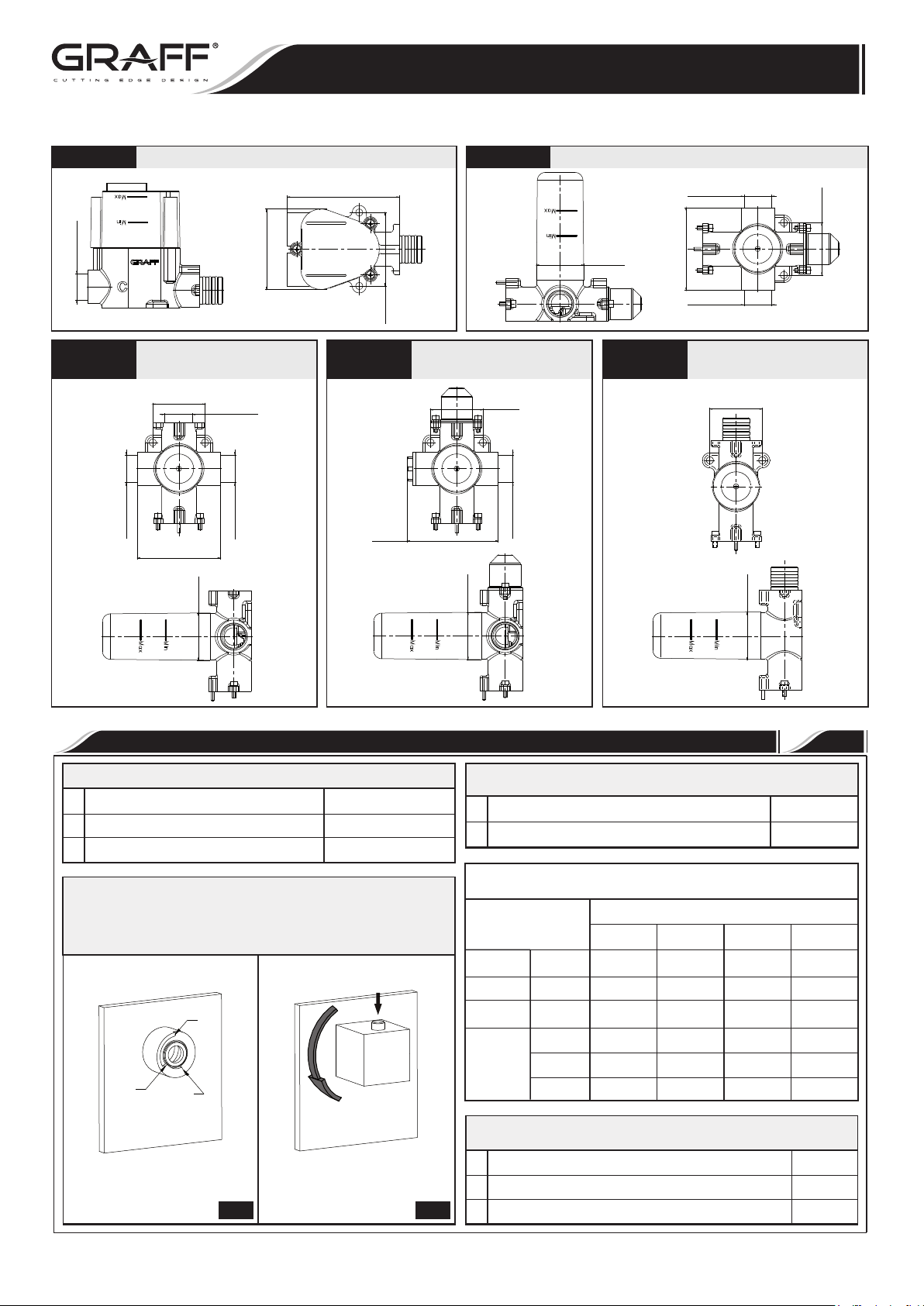
Concealed thermostat module - rough Concealed 2-way diverter module - rough
4-3/8”
(111mm)
Installation Instructions Instrucciones de Instalación
G 3/4-14NPT
2-1/16”
(52mm)
G 3/4-14NPT
3-1/8”
Concealed 3-way
diverter module - rough
2-1/16”
(52mm)
G 3/4-14NPT
G 3/4-14NPT
3-1/4”
(82mm)
Ø1-7/8”
G 3/4-14NPT
(47mm)
(80mm)
2-7/8”
G-8076
3-9/16”
(90mm)
(73mm)
Concealed cut-off
valve module - rough
Ø1-7/8”
(47mm)
2-1/16”
(52mm)
Ø1-7/8”
(47mm)
G-8077
G 3/4-14NPT
3-1/4”
(82mm)
G 3/4-14NPT
Concealed cut-off
valve module - rough
2-1/16”
(52mm)
Ø1-7/8”
(47mm)
TECHNICAL INFORMATION INFORMACIÓN TÉCNICA
Water pressure in the installation • Presión de agua en la instalación
Minimum, mínima.
1
Maximum, máxima.
2
Recommended, recomendada.
3
To achieve the flow of water with temperature more than 38 °C,
press the lock on the lever of thermostat and turn the lever
counterclockwise (Fig. B) • Para conseguir el flujo de agua a la
temperatura por encima de 38 °C hay que apretar el bloqueo en la
palanca del termostato y girar la palanca en el sentido contrario a
las agujas del reloj (Fig. B).
2
3
1
A B
7 psi (~0,5 bar)
70 psi (~5 bar)
15-45 psi (~1-3 bar)
Water temperature in the installation • Temperatura de agua en la
instalación
Cold, fría.
1
Hot, caliente.
2
Thermostatic Shower Rough Valve Flow Rates (gal/min) • Los flujos
de termóstato en conexión a:
Model
G-8006
G-8076
G-8052
G-8053
Temperature range of thermostat operation (Fig. A) • Alcance de
temperaturas de trabajo del termostato (Fig A)
Minimum, mínima.
1
Lock, bloqueo.
2
Maximum, máxima.
3
3/4” 8.19 11.62 12.94 14 .79
3/4” 8.98 12.15 13.21 14 .79
3/4” 7.4 10.57 12 .15 13 .74
o 7.93 11 .1 12.42 13 .74
oo 7.4 10.3 11 .62 13.47
ooo 7.13 10 .04 11.62 13 .21
20 psi 40 psi 60 psi 80 psi
Pressure (psi)
>59°F
< 140 °F
61°F
100°F
115°F
2
IOG 2858.00
2
Rev. 4 December 2015

This faucet complies with NSF61/9, ASME/ANSI A112.18.1
and CSA B 125 Standards.
Este grifo se encuentra conforme con losestandares de NSF61/9,
de ASME/ANSI A112.18.1 y de CSA B 125.
THERMOSTATIC SET
CONJUNTO TERMOSTÁTICO
Installation Instructions Instrucciones de Instalación
G-8076 cut-off valve
C.1
Flow rate information for 2-way valve Información de intensidad de flujo para válvula de 2 vías
90°
14,5 psi (1 bar)
29,0 psi (2 bar)
43,5 psi (3 bar)
58,0 psi (4 bar)
72,5 psi (5 bar)
Flow rate information for 3-way valve Información de intensidad de flujo para válvula de vías
14,5 psi (1 bar)
29,0 psi (2 bar)
43,5 psi (3 bar)
58,0 psi (4 bar)
72,5 psi (5 bar)
6,0
8,3
10,0
11,5
12,7
0°
0
0
0
0
0
10,6
45°
4,6
6,4
8,1
9,2
10,0
60°
5,0
6,8
8,5
9,5
60°
5,5
7,7
9,7
11,0
12,1
•
75°
5,0
6,9
8,7
9,4
10,5
30°
2,7
4,0
5,1
5,5
6,1
•
120°
0
0
0
0
0
G-8052 2-way diverter
180°
6,2
6,2
8,6
8,6
10,5
10,5
11,9
11,9
13,1
13,1
30°
3,2
4,3
5,0
5,7
6,3
195°
5,5
7,5
8,9
9,7
11,2
0°
0
0
0
0
0
165°
5,1
5,1
6,9
6,9
8,5
8,5
9,8
9,8
10,6
10,6
60°
5,3
7,1
8,6
10,0
10,8
240°
0
0
0
0
0
C.2
285°
4,5
6,3
7,7
9,2
10,2
G-8053 3-way diverter
90°
6,0
8,4
10,1
11,6
12,9
300°
5,4
7,5
9,2
10,6
11,7
GPM
GPM
GPM
GPM
GPM
315°
5,1
6,9
8,3
9,4
10,8
GPM
GPM
GPM
GPM
GPM
90 °
C.3
60°
300°
240°
G-8077 cut-off valve
0°
30°
30°
OFF
0°
OFF
OFFOFF
180°
C.4
60 °
90°
D.1
60°
120°
D.2
ENGLISH
For the installation of every valve irrespective of the thermostat
localization use dedicated pipe connectors. Do not use gas burner while
installing pipes (Fig. D).
~
ESPANOL
Para instalar cada una de las válvulas independientemente de la
ubicación del termóstato hay que usar los manguitos dedicados.
Durante la instalación de los tubos no se puede usar el
quemador (Fig. D).
E
IOG 2858.00
3
Rev. 4 December 2015
 Loading...