

Page 1
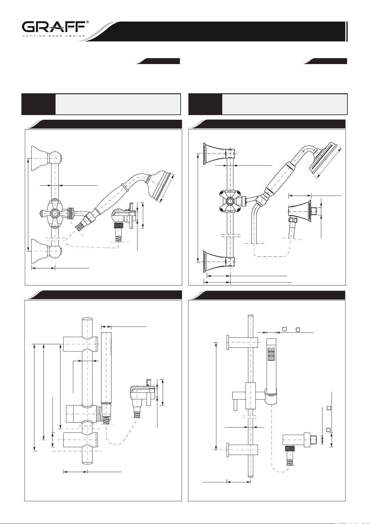
HAND-HELDSHOWERWITH WALL-MOUNT SLIDEBAR
DUCHADE MANOCONAGARRADOR CON MONTADURABARA DESLIZADOR
This faucet complies with NSF61/9, ASME/ANSI A112.18.1
and CSA B 125 Standards.
Este grifo se encuentra conforme con losestandares de NSF61/9,
de ASME/ANSI A112.18.1 y de CSA B 125.
Dear Customer Estimado Cliente
ENGLISH
Thank you for selecting our product. We are confident we can fully satisfy Muchas gracias por elegir nuestro producto. Estamos seguros que podemos
your expectations by offering you a wide range of technologically advanced satisfacer completamente sus expectativas ofreciéndole una amplia variedad
products which directly result from our ma
ny years of experience in faucet de productos tecnol
and fitting production. muchos años de experiencia en grifos y su producción apropiada.
Installation Instructions Instrucciones de Instalación
~
ESPANOL
ógicamente avanzados que resultan directamente de
ATTENTION!
)mm745(
"23/71-12
For care, use soft towel with soap and water only! Under no
circumstances should you use any chemicals.
Model
8600
Modelo
Ø Ø23/32" ( 18mm)
Ø
( 77mm)
)mm46(
3-1/32"
Ø
Ø
"46/33-2
TPN41-"2/1
Ø
2-5/16" (58,6mm)
ATENCIÓN!
)mm745(
”61/9-12~
Para el cuidado, utilice solamente una toalla suave con jabón
y aqua! Bajo ninguna circunstancia no use productos químicos.
Model
8650, 8656
Modelo
( 18mm)
ØØ11/16”
(Ø107mm)
Ø4-1/4”
(50mm)
1-15/16”
TPN41-"2/1
2-5/8 (67mm) Finezza Due
2-15/16 (74mm) Finezza Uno
Model
Modelo
8610
Model
Modelo
8620
Ø Ø1-7/64" ( 28mm)
1"
( 25mm)
)mm52(
)mm5( 05
)mm5( 08
)mm( 016
Ø
"46/36
"23/12-12.nim
Ø
2lanimon "46/35-2
)mm5(
4.xam "46/1-2
Ø3
"8/-
Ø 31
)mm6(
Ø 5
"61/9-2
TPN41-"2/1
Ø
(620mm)
Ø15/32"
( 12mm)Ø
( 35mm)
1-3/8"
1/2"-14 NPT
~24-13/32"
2-5/16" (58,6mm)
2-5/16"
(58.8mm)
IOG 2086.31
1
Rev. 19 October 2017
Page 2
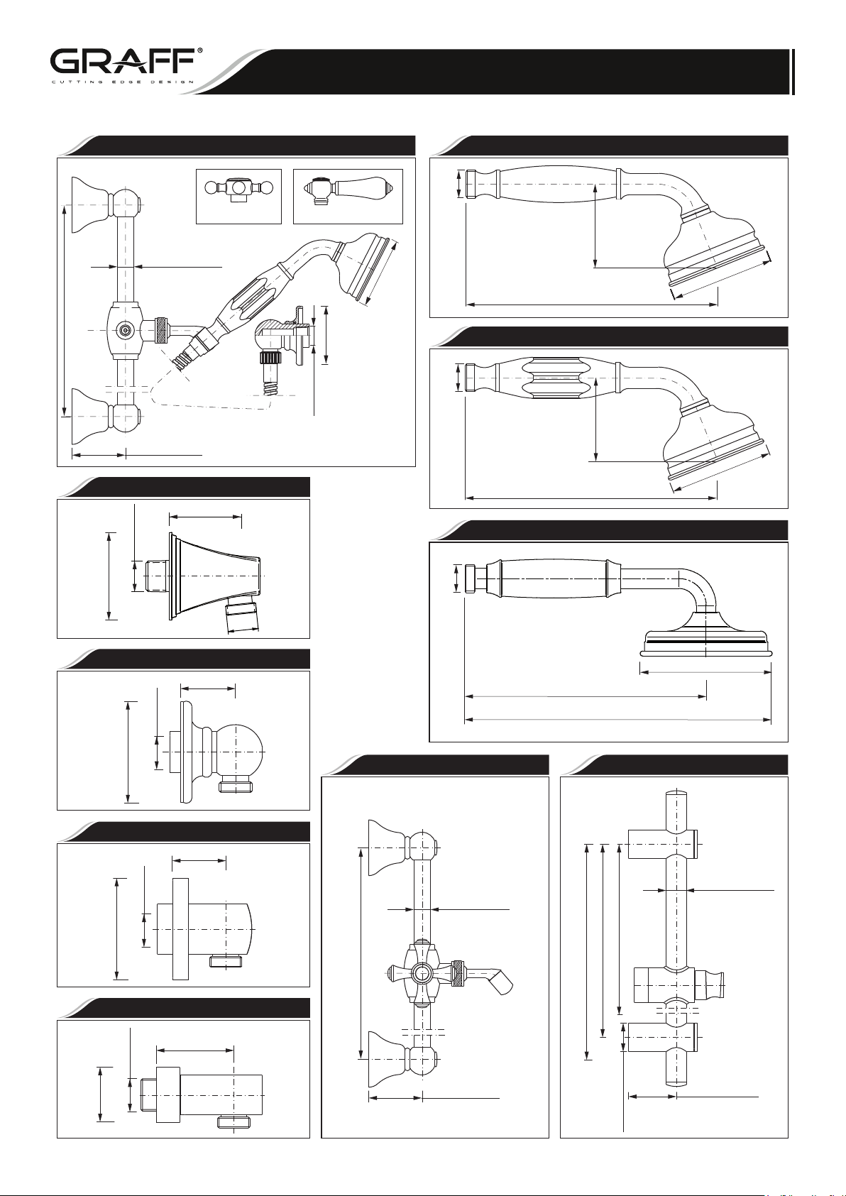
DUCHADE MANOCON AGARRADOR CON MONTADURABARA DESLIZADOR
This faucet complies with NSF61/9, ASME/ANSI A112.18.1
and CSA B 125 Standards.
Este grifo se encuentra conforme con losestandares de NSF61/9,
de ASME/ANSI A112.18.1 y de CSA B 125.
HAND-HELD SHOWERWITH WALL-MOUNTSLIDE BAR
Installation Instructions Instrucciones de Instalación
Model
CanterburyCollection 8630-C2S, 8630-LC1S
Modelo
"2
/
1G
"
C2S – Cross Handle
ØØ23/32"
)mm745(
( 18mm)
"23/71-12
2-5/16"
(58,6mm)
Model
Modelo
LC1S – Porcelain Lever Handle
T
P
N
4
1-"
2/
1
8643
)
m
Ø
( 77m
)mm46(
Ø
"46/32-2
Ø
/32"
-1
3
Ø
"2/1G
~7 "
-13/32
~7 "
-13/32
)
23/51-
m
m5
.2
6(
2
(~188mm)
Model
Canterbury Collection 8634
Modelo
"
)m
2
3
/51
m5
.2
-
6
(
2
(~188mm)
Model
8604
Modelo
77mm)
Ø
(
-1/32
3 "
Ø
( )Porcelain Handle
Ø
( 77mm)
"
-1/32
3
Ø
1-15/16”
)mm26(
61/7-2
1/2-14 NPT
(50mm)
"
2
/1G
Model
Modelo
8724
G1/2
Model
8603
Modelo
TPN41-”2/1
Ø )mm56
(
”61/9-2
Ø
TPN41-”2/1
(Ø )mm56
”61/9
-2
Ø
1-3/8”
(35mm)
1-5/16”
(34mm)
Model
Modelo
Model
Modelo
8613
8623
1(
9
7
m
m
7
3/-
Model
Modelo
ØØ23/32"
)mm745(
"
2
3/7
112
( 18mm)
)
4
"
(
m152
/7-9
8
"
)mm
)mm085(
0
)
55(
m
"
m
"2
2
0
3
16(
/
12-
"
12
6
/
2
1
.
-
lanimon 46/35-
ni
4
2.xam 4
m
4-3/16”
(Ø107mm)
Ø
m
)
Model
86118601
Modelo
( 25mm)
ØØ63/64"
TPN41-”2/1
(50mm)
1-15/16”
)mm5
”8/3-1
2-5/16"
3□(
□
(58,6mm)
)
m
m
5
3(
Ø
"
83
2 "-5/16
(58. mm)6
Ø /-1
IOG 2086.31
2
Rev. 19 October 2017
Page 3
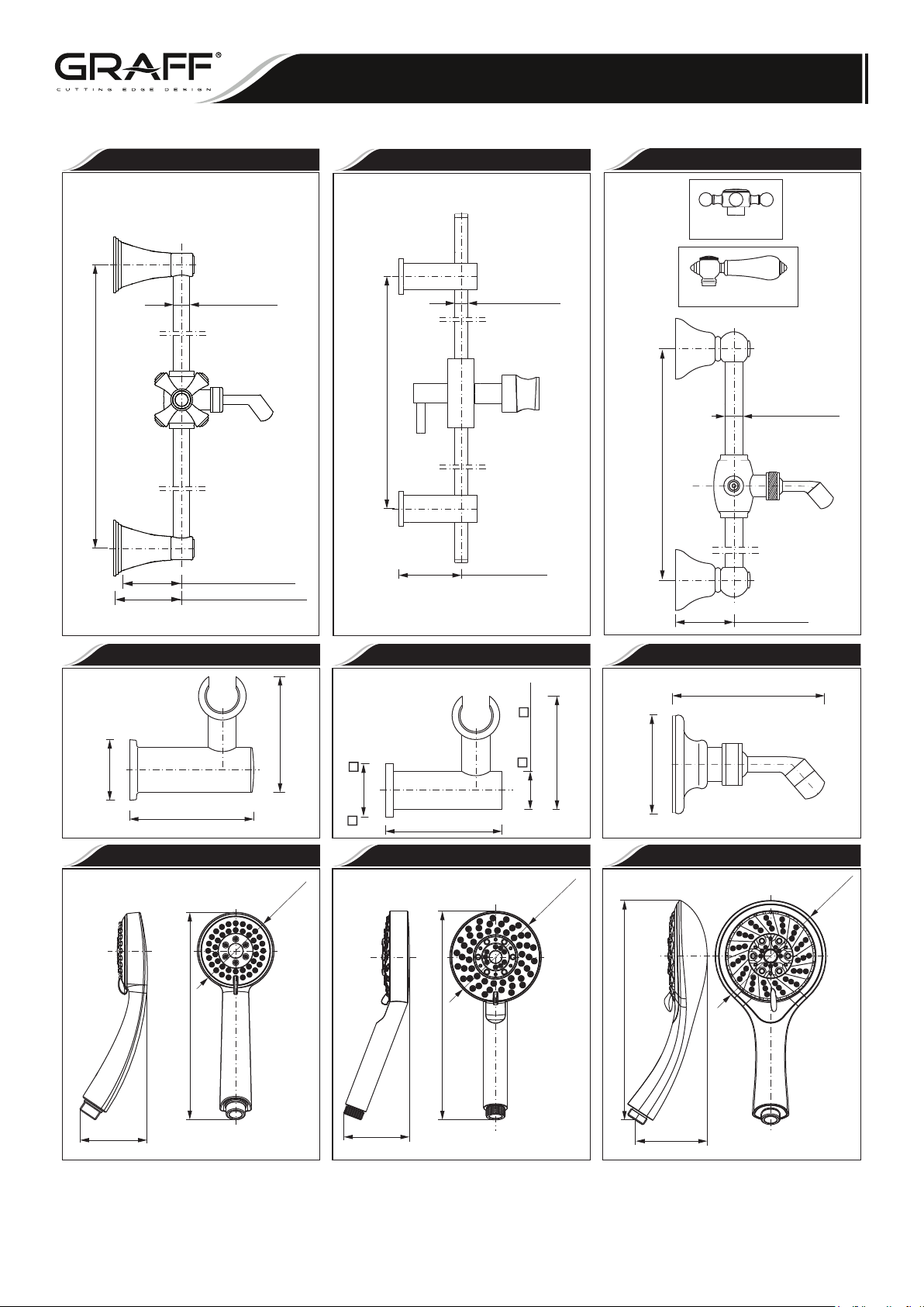
DUCHADE MANOCON AGARRADOR CON MONTADURABARA DESLIZADOR
This faucet complies with NSF61/9, ASME/ANSI A112.18.1
and CSA B 125 Standards.
Este grifo se encuentra conforme con losestandares de NSF61/9,
de ASME/ANSI A112.18.1 y de CSA B 125.
HAND-HELD SHOWERWITH WALL-MOUNTSLIDE BAR
Installation Instructions Instrucciones de Instalación
Model
8651, 8661
Modelo
(18mm)
Ø11/16”
)mm026~(
)
mm745(
”61/9-12~
"42~ 23/31-
ØØ15/32"
Model
Modelo
( 12mm)
8621
Model
8631-C2S, 8631-LC1S
Modelo
C2S – Cross Handle
LC1S – Porcelain Lever Handle
)mm745(
ØØ23/32"
( 18mm)
"23/71-12
2-5/8 (67mm) Finezza Due
2 "-5/16 (59mm)
2-15/16 (74mm) Finezza Uno
2-5/16"
(59 mm)
Model
8642
Modelo
)(Ø mm04
)mm67~(
"3~
( mm53 )
"8/3-1
Ø "46/73-1
3-15/64"
)mm622(
"8/7-8
( )82mm
Model
Modelo
8664
Ø3-5/16"
( Ø84mm)
3-1/32"
77mm( )
)mm822(
"61/51-8
Model
Modelo
Model
Modelo
8622
)
mm52(
46/36
8674
Ø3-15/16"
(
)( mm57~
"46/16-2~
Ø100mm)
Model
8602
Modelo
3-15/16"
)(
mmØ 56
100mm( )
"61/9-2
Ø
Model
8684
Modelo
Ø4-3/4"
Ø121mm)
(
)mm042(
"61/7-9
2-7/8" (73mm)
IOG 2086.31
2-13/16"
(72mm)
3-1/8" (79mm)
3
Rev. 19 October 2017
Page 4
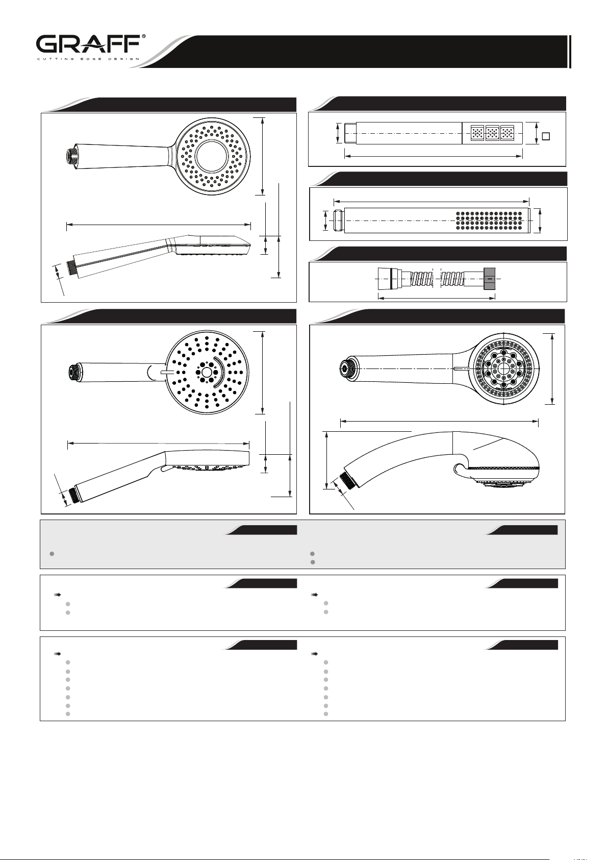
DUCHADE MANOCON AGARRADOR CON MONTADURABARA DESLIZADOR
This faucet complies with NSF61/9, ASME/ANSI A112.18.1
and CSA B 125 Standards.
Este grifo se encuentra conforme con losestandares de NSF61/9,
de ASME/ANSI A112.18.1 y de CSA B 125.
Model
Modelo
HAND-HELD SHOWERWITH WALL-MOUNTSLIDE BAR
Installation Instructions Instrucciones de Instalación
8704
"2/1G
~7 "
- 5/161
(~202mm)
Modelo
Model
Model
Modelo
8644
8644
”1
)mm52(
G1/2"
G1/2"
(248mm)
9-3/4”
10-1/8” (257mm)
Model
Modelo
Ø4-1/8” (105mm)
(25mm)
2-1/4” (57mm)
1”
8734
Ø4-3/4” (120mm)
1-1/8”
(25mm)
3” (76mm)
2/1G
(69mm)
2-11/16”
~7-3/4"
59"
(~198mm)
(1500 )mm
9-3/8” (237mm)
Model
Modelo
Model
Modelo
Model
Modelo
8714
"1
Ø
8605
8744
)mm52Ø(
Ø3-5/16” (84mm)
G1/2"
ENGLISH
FLOW RATE INFORMATION
Max flow rate 1.5gpm(5.7 L/min.) at 60psi(4.1 bar) Flujomáximo1.5 gpm(5.7 L/min.) con60 psi(4.1 bar)
Max flow rate G-8724 1.8gpm(6.8L/min.) at 60psi(4.1 bar) Flujomáximo G-8724 1.8 gpm(6.8 L/min.) con60 psi(4.1 bar)
ENGLISH
GRAFF product you will need:
to READ ALL the instructions completely before beginning,
to READ ALL the warnings, care and maintenance
information.
ENGLISH
You should have the following tools:
1/4" (6mm) carbide drill bit,
electric drill,
Phillips screwdriver,
level,
strap wrench,
1/2" iron pipe nipple,
Teflon® tape.
INFORMACIÓN DEINTENSIDADDE FLUJO
Para la instalación fácil de su producto de la GRAFF usted necesitará:
LEER TODAS las instrucciones completamente antes de comenzar,
LEER TODA la información sobre las advertencias, cuidado y
mantenimiento.
Usted debe tener las herramientas siguientes:
broca de carburo de 1/4" (6mm),
toladro electrico,
desarmador Phillips,
nivel,
llave de correa,
entrerrosca de tubo de hierro de 1/2",
cinta adhesiva deTeflon®.
~
ESPANOL
~
ESPANOL
~
ESPANOL
IOG 2086.31
4
Rev. 19 October 2017
Page 5
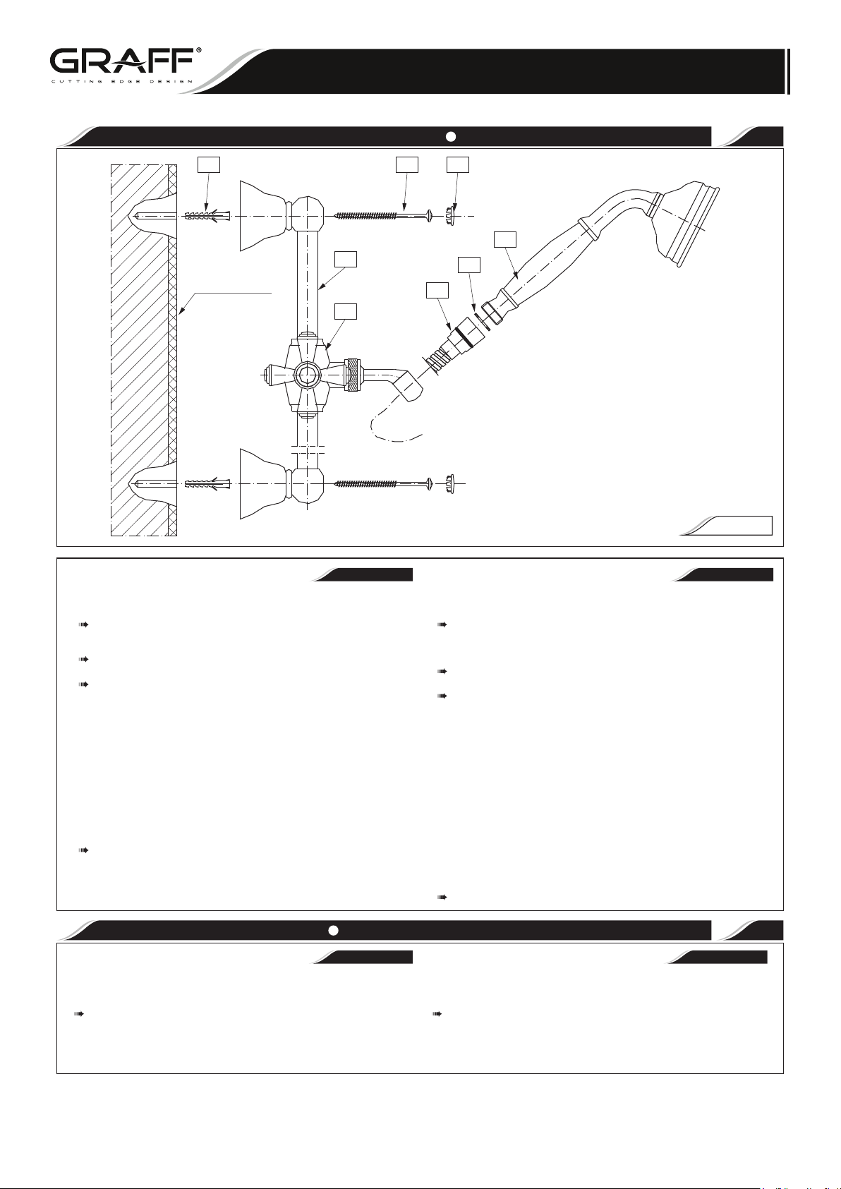
DUCHADE MANOCON AGARRADOR CON MONTADURABARA DESLIZADOR
This faucet complies with NSF61/9, ASME/ANSI A112.18.1
and CSA B 125 Standards.
Este grifo se encuentra conforme con losestandares de NSF61/9,
de ASME/ANSI A112.18.1 y de CSA B 125.
MOUNT WALL BAR INSTALE LA BARRA DE LA PARED
HAND-HELD SHOWERWITH WALL-MOUNTSLIDE BAR
Installation Instructions Instrucciones de Instalación
1
A
Finished wall
Acabado de
la pared
4
1
ENGLISH
B 3
6
5a
8600, 8601, 8610, 8611 models
See fig. 1 Vea dis. 1
Select wall position for wall bar based on family`s needs. Locate so there
will be slack in the hose when hand shower is in extreme up or down
position.
The slide mechanism (1) must be on the bar before mounting it to the
brackets (2).
Remove the upper and lower bracket caps (3) to expose the interior bracket
screw hole. Mate the bracket to the bar (4). Position wall bar (4) at the
desired location. Mark the top drill hole first and proceed to drill a 1/4" hole.
For ceramic tile installation: drill 1/4" hole in grout (if possible) and insert
anchor.
For fiberglass/acrylic surfaces: use a toggle bolt (notincluded). Insert
anchor (A) into drill hole. With the wall bar attached, position the wall
bracket over the hole, insert and tighten the screw (B). Do not fully tighten
the screw (B) until after you have completed the bottom installation. Using
a level, position the bar (4) in a vertical position and mark the bottom
location hole and drill a 1/4" hole. Insert anchor and complete the installation by fastening the bottom screw. Tighten both ends. Align and snap the
bracket
caps (3).
Mount the hand shower (7).
8631-C2S (-LC1S) models
Escoja la posición en la pared para la barra basada en los requisitos
necesarios de la familia. Localice la posición de manera que quede la
manguera floja cuando la regadera de mano esté en posición extrema,
hacia arriba o hacia abajo.
El mecanismo de deslizamiento (1) debe estar en la barra antes de instalar
los soportes (2).
Quite las tapas de los soportes (3) de arriba y de abajo para dejar
expuesto el hoyo del tornillo en el interior del soporte. Empareje el soporte
con la barra (4). Coloque la barra (4) de pared en la ubicación deseada.
Marque el hoyo de perforación de arriba primero y proceda a taladrar un
hoyo de 1/4".
Para la instalación en losas de cerámica: taladre un hoyo de 1/4" en la
grieta entre las losas (si es posible) e introduzca el ancla.
Para superficies de vidrio fibroso/acrílicas: use un tornillo fiador (no
están incluidos). Introduzca el ancla (A) dentro del hoyo perforado. Con la
barra de pared fija, coloque el soporte de pared sobre del hoyo, introduzca
y apriete el tornillo (B). No apriete el tornillo (B) completamente hasta que
no haya completado la instalación de abajo. Usando un indicador de nivel,
coloque la barra (4) en una posición vertical y marque el sitio del hoyo de
abajo y perfore un hoyo de 1/4". Introduzca el ancla y complete la
instalación fijando el tornillo deabajo. Apriete ambos extremos. Alineé y
coloque las tapas de los soportes (3) inferiores.
Instale la regadera de mano (7).
7
8600, 8601, 8610, 8611 modelos
8631-C2S (-LC1S) modelos
FIG. 1
~
ESPANOL
Connect tapered end of hose to hand shower Conecte el extremo ahusado de la manguera a la regadera de mano
ENGLISH
See fig. 1 Vea dis. 1
Seat the washer (6) firmly into the hose nut (a5). Carefully align the thread
of the tapered end of the hose (a5) directly to the hand shower (7). Hand
tighten – do not use a wrench or pliers. Then place the hand shower (7)
into the wall mount holder.
IOG 2086.31
8600, 8604, 8610, 8614, 8605 models
8630-C2S (-LC1S), 8634 models
5
2
~
ESPANOL
8600, 8604, 8610, 8614, 8605 modelos
8630-C2S (-LC1S), 8634 modelos
Coloque la arandela (6) firmemente dentro de la tuerca de la manguera
(5a). Cuidadosamente alineé la rosca del extremo ahusado de la
manguera (5a) directamente a la regadera de mano (7). Luego coloque la
regadera de mano (7) en el sujetador de la montura para la pared. Apriete
a mano – no use una llave de tuercas o alicates.
Rev. 19 October 2017
Page 6
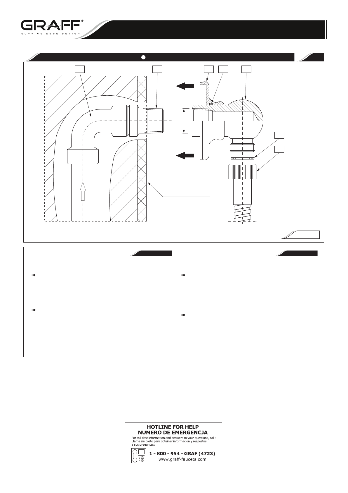
HAND-HELD SHOWER WITHWALL-MOUNT SLIDEBAR
DUCHADEMANO CON AGARRADOR CONMONTADURABARADESLIZADOR
This faucet complies with NSF61/9, ASME/ANSI A112.18.1
and CSA B 125 Standards.
Este grifo se encuentra conforme con losestandares de NSF61/9,
de ASME/ANSI A112.18.1 y de CSA B 125.
Installation Instructions Instrucciones de Instalación
SUPPLY ELBOW INSTALLATION INSTRUCCIONES PARA EL CODO ABASTECEDOR 3
DD C 9 10 8
T
P
N4
1
-
"
2
/1
11
5b
Finished wall
Acapada de la pared
ENGLISH ESPANOL
8600, 8603, 8610, 8613 models
See fig. 2 Vea dis. 2
Apply Teflon® tape to threaded ends of 1/2" (13mm) iron pipe nipple (C)
(not supplied) and thread into shower riser elbow (D) so that nipple extends
past the finished wall no more than 1/2" (13mm) and no less than 1/4"
(6mm). Screw the supply elbow (8) onto the nipple (C) making sure that
supply elbow outlet is in a downward facing position. Slide the escutcheon
(9) with o-ring seal (10) over the supply elbow (8) and against the finished
wall.
Seat the washer (11) firmly into the hose nut (5b). Attach the shower hose
to the threaded supply outlet and proceed with the installation of the hand
shower (7). CAUTION: To avoid damage to the supply elbow or hose finish
during installation, wrap with a cloth or tape and use only a smooth-jawed
wrench. Do not overtighten connections.
8630-C2S - LC1S, 8605 models
Aplique cinta Teflon® a las puntas roscadas de la entrerrosca de tubo de
hierro de 1/2" (13mm) (C) (no proporcionado) y enrósquelo en el codo del
tubo (D) vertical de suministro de manera que la entrerrosca no atraviese
la pared acabada más de 1/2" (13mm) y no menos de 1/4" (6mm). Atornille
el codo del tubo de suministro (8) en la entrerrosca (C) asegurándose que
la toma del codo de suministro de agua quede en posición cara hacia
abajo. Deslice con cuidado el chapetón (9) con la sellador de anillo sobre
el codo del tubo de suministro (8) y contra la pared acapada.
Coloque la arandela (11) firmemente dentro de la tuerca de la manguera
(5b). Fije la manguera de la regadera a la toma de agua enroscada y
continúe con la instalación de la regadera de mano (7). ADVERTENCIA:
Para prevenir dańo al codo de abastecimiento o al acabado de la
manguera durante la instalación, envuelva con un trapo o cinta y use
solamente una llave de tuercas de mordaza lisa. No apriete demasiado
las conexiones.
FIG. 2
8600, 8603, 8610, 8613 models
8630-C2S - LC1S, 8605 models
IOG 2086.31
6
Rev. 19 October 2017
Page 7
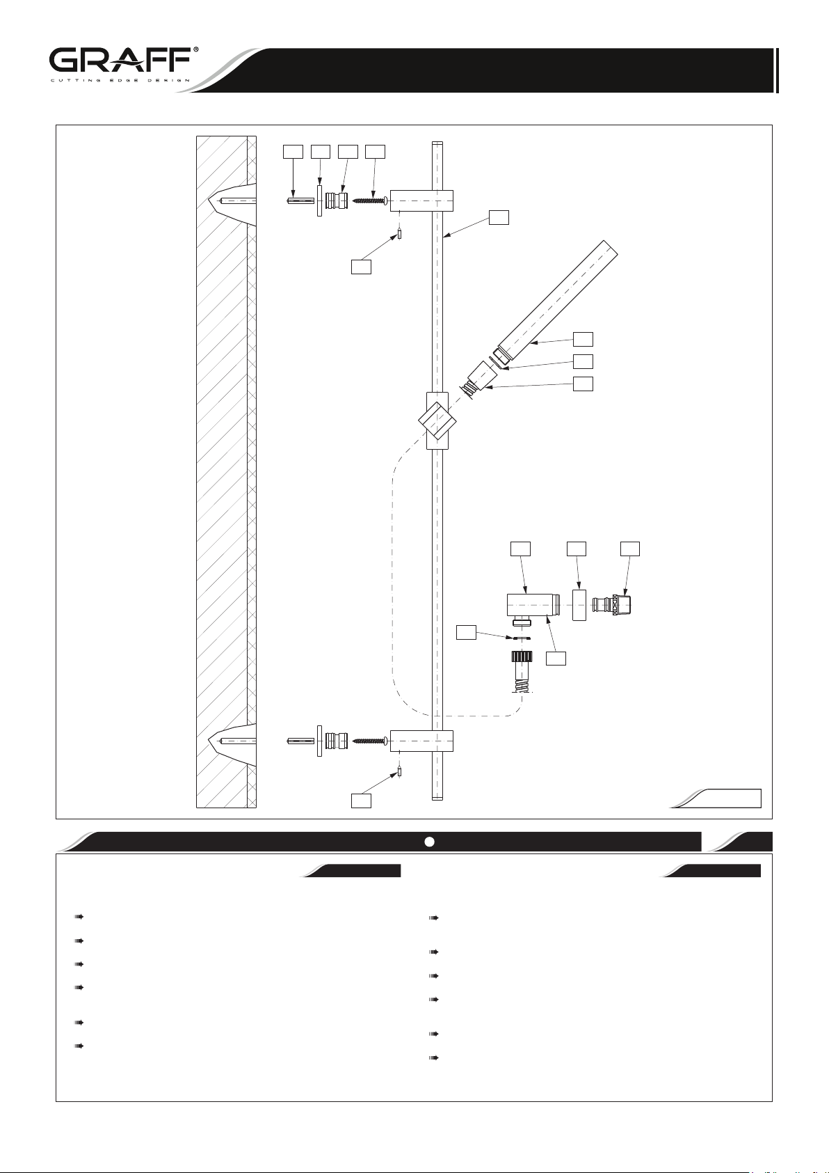
DUCHADEMANO CON AGARRADOR CONMONTADURABARADESLIZADOR
This faucet complies with NSF61/9, ASME/ANSI A112.18.1
and CSA B 125 Standards.
Este grifo se encuentra conforme con losestandares de NSF61/9,
de ASME/ANSI A112.18.1 y de CSA B 125.
12 9 10 11
13
HAND-HELD SHOWER WITHWALL-MOUNT SLIDEBAR
Installation Instructions Instrucciones de Instalación
1
2
3
4
5
6 7
3
8
13
ASSEMBLYOFHAND- HELDSHOWERWITH SQUARE HANDSET INSTALACIÓN DELJUEGO DEDUCHACUADRADA
ENGLISH
See fig. 3 8620, 8621, 8623, 8605, 8650, 8651 models Vea dis. 3 8620, 8621, 8623, 8605, 8650, 8651 modelos
Position the anchors (12) according with the spacing of the brackets, drill
Ø8mm holes and put in the anchor bolts.
Loosen the set screws (13) remove the sleeves (10) and escutcheons (9)
and assemble them with the screws (11) in previously made holes.
Put the shower bar (1) onto assembled sleeves and tighten the set screws
(13).
Prepare the supply elbow (5) for assembly. Loosen the set screw (8)
remove the sleeve (7) Put on the Teflon tape around the thread of the
sleeve and screw into previously prepared pipe supply in the wall.
On the assembled sleeve (7) put the body of supply elbow (5) with the
escutcheon (6) and tighten the set screw (8).
Connect the hose (4) to supply elbow (5). The conical ending of the hoses
hould be connected to shower handset (2). Remember about seals (3).
Determinar los sitios para tacos (12) en la pared de acuerdo con la
distribución de los soportes de la ducha, taladrar agujeros de Ø8mm y
meter en ellos los tacos.
Aflojar los tornillos (13), sacar los casquillos (10) con los rosetones (9) e
instarlos en los agujeros determinados (11).
Colocar la ducha (1) sobre los casquillos instalados y enroscar los tornillos
(13).
Preparar el empalme de ángulo (5) para el
sacar el casquillo (7), bobinar en la rosca un poco de la cinta de teflón y
enroscar sobre el borne de salida preparado en la pared.
Sobre el casquillo instalado (7) poner el cuerpo del empalme de ángulo (5)
junto con el rosetón (6) y apretar el tornillo (8).
Colocar la manguera (4) en el empalme de ángulo (5) por un lado, y por el
otro (con el cabezal cónico) a la teleducha (2), sin olvidar las juntas (3).
montaje. Aflojar el tornillo (8),
ESPANOL
FIG. 3
4
~
IOG 2086.31
7
Rev. 19 October 2017
Page 8
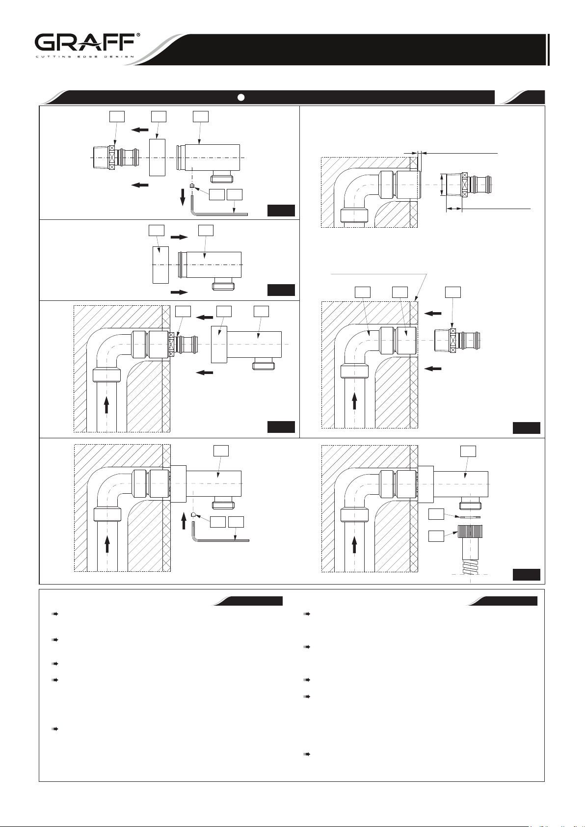
DUCHADE MANOCON AGARRADOR CON MONTADURABARA DESLIZADOR
This faucet complies with NSF61/9, ASME/ANSI A112.18.1
and CSA B 125 Standards.
Este grifo se encuentra conforme con losestandares de NSF61/9,
de ASME/ANSI A112.18.1 y de CSA B 125.
HAND-HELD SHOWERWITH WALL-MOUNTSLIDE BAR
Installation Instructions Instrucciones de Instalación
SUPPLY ELBOW INSTALLATION INSTRUCCIONES PARA EL CODO ABASTECEDOR
7 6 5
MAX. 5/64"
(MAX. 2mm)
TPN
4
1
A8
4.1
-"2
/1
MAX. 19/32"
(MAX.15mm)
6 5
Finished Wall
Acabado de la Pared
4.3
D C 7
7 6 5
5
4.4
5
A8
ENGLISH
Remove the set screw (8) using hex key (A) - see fig. 4.1. Slide carefully
the mounting sleeve (7) from the body of supply elbow (5). Remove
carefully the escutcheon from the body of supply elbow.
Apply Teflon® tape to threaded end of 1/2" lengthening pipe connector (C)
(not supplied) and thread into shower riser elbow (D) so that the connector
(C) extends past the finished wall no more than 5/64”(2mm) - see fig. 4.2.
Screw the mounting sleeve (7) into prepared shower riser elbow. Use
adjustable wrench. See fig. 4.2.
Slide escutcheon (1) on the stub pipe with o-ring seal of supply elbow body
(5) - see fig. 4.3. Then carefully slide the body of supply elbow with
escutcheon onto the mounting sleeve stub pipe (7) - see fig. 4.4. Place the
escutcheon (6) in the correct position make sure that the supply elbow
outlet is in a downward facing position. Tighten the set screw (8) using hex
key (A) - see fig. 4.5.
Seat the washer (3) firmly into the hose nut (4) - see fig. 4.6. Attach the
shower hose to the threaded supply outlet and proceed with the installation
of the hand shower.
4.2
5
3
4
5.4
~
ESPANOL
Destornille el tornillo de fijación (8) con la llave allen (A) - ver el dis. 4.1.
Saque con precaución el casquill
tubo de suministro. Deslice con precaución el chapetón (6) del cuerpo del
codo del tubo de suministro (5).
Aplique cinta Teflon
roscado (C) (no proporcionada) y enrósquela en el codo del tubo (D)
vertical de suministro de manera que el tubo roscado no atraviese la
pared de acabado más de 5/64”(2mm) - ver el dis. 4.2.
Enrosque el casquillo de montaje (7) al codo del tubo preparado antes.
Use la llave ajustable. Ver el dis. 4.2.
Ponga el chapetón (6) sobre la pieza de unión y el anillo o-ring del cuerpo
de la codo del tubo de suministro (5) - ver el dis. 4.3. Luego ponga con
precaución el cuerpo de la codo del tubo y el chapetón en el tubo roscado
del casquillo de montaje (7) - ver el. dis. 4.4. Posicione el chapetón (6)
correctamente asegurándose que la toma del codo de suministro de agua
quede en posición cara hacia abajo. Apriete el tornillo fijación (8) con la
llave allen (A) - ver el dis. 4.5.
Coloque la arandela (3) firmemente dentro de la tuerca de la manguera
ver el dis. 4.6. Fije la manguera de la regadera a la toma de agua
(4) enroscada y continúe con la instalación de la regadera de mano.
®
a la punta roscada de la pieza de unión del tubo
o de montaje (7) del cuerpo del codo del
IOG 2086.31
8
Rev. 19 October 2017
Page 9
HAND-HELD SHOWER WITHWALL-MOUNT SLIDEBAR
DUCHADEMANO CON AGARRADOR CONMONTADURABARADESLIZADOR
This faucet complies with NSF61/9, ASME/ANSI A112.18.1
and CSA B 125 Standards.
Este grifo se encuentra conforme con losestandares de NSF61/9,
de ASME/ANSI A112.18.1 y de CSA B 125.
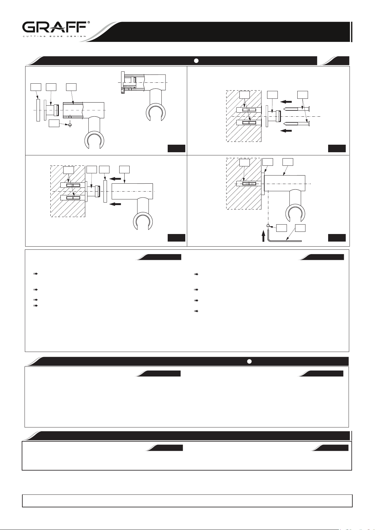
WALL BRACKET FOR HANDSHOWER ASSEMBLY MONTAJE DEL AGARRADOR DE PUNTO
Installation Instructions Instrucciones de Instalación
6
2 3
1
3 BA
4
5.1 5.2
A
A
3 2 1
2 1
4 C
5.3
ENGLISH
See fig. 5.1-5.4 For model 8622: Vea dis. 5.1-5.4 Para el modelo 8622:
Disassemble the wall bracket as show on fig.5.1: Remove escutcheon (2), lossen
the set screw (4) using the included hex key (C), slide out the mounting sleeve
from the bracket body (1).
Choose the location of the bracket on the wall. Drill 5/16”(8mm) hole and put the
anchor (A) into the hole.
Tighten the mounting sleeve (3) using the mounting screw (B) as show on fig.5.2.
Slide the escutcheon (2), on the assembled mounting sleeve (3). Then slide the
bracket body (1) fig.5.3. After positioning the bracket body In the correct position,
secure it with the set screw (4) using the hex key (C) as shown on fig.5.4.
In case of 8602 and 8642 models the mounting sleeve is not included the wall
bracket is fixed to the wall directly using the mounting screw.
Desmontar el agarrador de puntos como en el dis.5.1: quitar el rosetón (2),
destornillar el tornillo sin fin (4) con la llave allen (C) adjunta, sacar el casquillo
de montaje (3) del cuerpo del agarrador (1).
Determinar en la pared los sitios para montar el agarrador de punto. Taladrar un
agujero de 5/16”(8mm) y meter el taco (A) en el foro.
Apretar el casquillo de montaje (3) con el tornillo de montaje (B) como en el
dis.5.2.
Sobre el casquillo de montaje instalado (3) insertar el rosetón (2), luego poner
el cuerpo del agrrador (1) dis.5.3. Después de haber colocado el cuerpo en
posición correcta, asegurarlo con el tornillo sin fin (4) con la llave allen (C) como
en el dis.5.4.
En caso de los modelos 8602 y 8642 no hay casquillo de montaje el agarrador
de punto tiene que instalarse en la pared directamente con el tornillo de
montaje.
~
ESPANOL
5.4
CARE AND MAINTENANCE CUIDADO Y MANTENIMIENTO
ENGLISH
Your Graff product is designed and engineered in accordance with the highest quality and
performance standards. Be sure not to damage the finish during installation. Care should
be given to the cleaning of this product. Although its finish is extremely durable, it can be
damaged by harsh abrasives or polish.Never use abrasive cleaners, acids, solvents,
etc. to clean any Graff product. To clean, simply wipe gently with a damp cloth and
blot dry with a soft towel.
ENGLISH
Warranty conditions and warranty registration card are outlined on a
separate sheet.
All dimensions and drawings are for reference only. For details, please refer to actual products.
Todas las dimensiones y dibujos sirven únicamente de referencia. Para consultar detalles, ver los productos.
IOG 2086.31
~
ESPANOL
Su producto de la Graff esta diseñado y se regido de acuerdocon los estándares de
funcionamiento y calidad más altos. Esteseguro no dañar las terminaciones del grifo
durante la instalación. Cuide el producto manteniendolo siempre limpio. Aunque
suacabado es extremadamente durable, puede ser dañado por losabrasivos o pulientes
ásperos. Nunca utilice limpiadoresabrasivos, ácidos, solventes, el etc. para limpiar
cualquierproducto de la Graff. Para limpiar, simplemente use un paño húmedo y
seque con una toalla suave.
WARRANTY GARANTÍA
ESPANOL
Las condiciones de la garantía y la tarjeta del registro de la garantía se
encuentran en una pagina separada.
9
Rev. 19 October 2017
~
 Loading...