

Page 1
PRESSURE BALANCE TUB & SHOWER
LA DUCHA CON GRIFO DE TINA EQUILIBRANTE DE LA PRESIÓN
This product complies with NSF61/9, ASME/ANSI A112.18.1
and CSA B 125 Standards.
Este se encuentra conforme con losestandares de NSF61/9,
producto
de ASME/ANSI A112.18.1 y de CSA B 125.
Dear Customer Estimado Cliente
ENGLISH
Thank you for selecting our product. We are confident we can fully satisfy Muchas gracias por elegir nuestro producto. Estamos seguros que podemos
your expectations by offering you a wide range of technologically advanced
products which directly result from our many years of experience in faucet
and fitting production.
For care, use soft towel with soap and water only! Under no
circumstances should you use any chemicals. For products
ATTENTION!
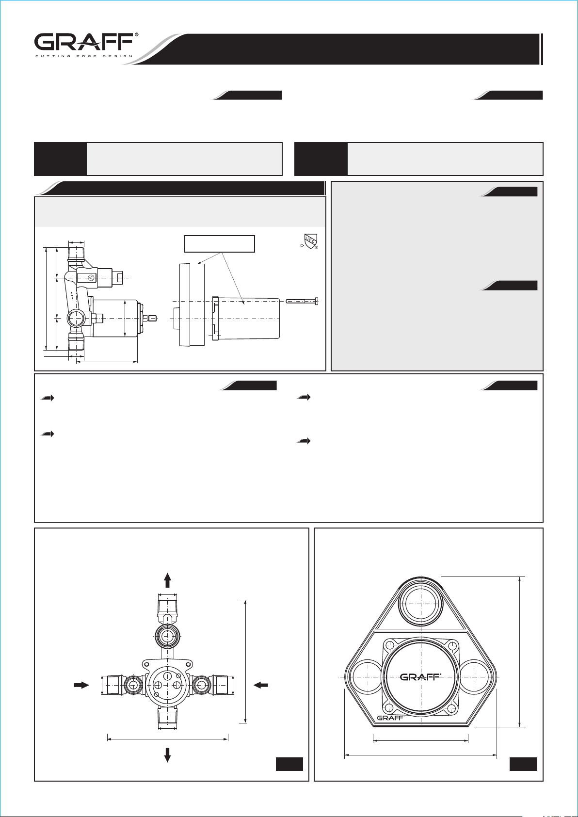
Válvula Mezcladora Equilibrante de la Presión para Bañera con Desviador
1-39/64"
2-11/64"
5-15/32" (139mm)
1-11/16"
1/2NPT-14
with decorative finishes please be extra careful not to
damage, scuff or ruin the finish during the installation and
cleaning!
Pressure Balanced Bath Mixing Valve with Diverter (Rough Only)
(sólo para empotrar)
1/2NPT-14
(41mm)
SHR
TUB
(55mm)
(43mm)
HOT
3-17/64" (83mm)
(Ø50mm)
Ø1-31/32"
PLASTER GUARD
PROTECTOR DEL YASO
Installation Instructions Instrucciones de Instalación
~
ESPANOL
satisfacer completamente sus expectativas ofreciéndole una amplia variedad
de productos tecnológicamente avanzados que resultan directamente de
muchos años de experiencia en grifos y su producción apropiada.
Para el cuidado, utilice solamente una toalla suave con jabón y aqua!
Bajo ninguna circunstancia no use productos químicos. Con los
productos con el acabado decorativo hay que tener un cuidado
especial para no dańar, arańar o destruir el acabado durante su
instalación o limpieza!
ENGLISH
Diverter function requires a minimum of 35 PSI (2.4 bar)
to operate.
FLOW RATE INFORMATION
Maximum flow rate at showerhead is 2.5 gpm
(9.5L/min.) at 80 PSI (5.5 bar)
~
ESPANOL
El funcionamiento del desviador requiere 35 PSI
(2.4 bares) como mínimo.
INFORMACIÓN DE INTENSIDAD DE FLUJO
El flujo máximo en la ducha es de 2.5 gpm (9.5 l/min.) con
80 PSI (5.5 bares)
Model
Modelo
ATENCIÓN!
7055
ENGLISH
ESPANOL
For easy installation of your Para la instalación fácil de su producto
GRAFF product you will need: de la GRAFF usted necesitará:
to READ ALL the instructions completely before beginning, LEER TODAS las instrucciones completamente antes de comenzar,
to READ ALL the warnings, care and maintenance information. LEER TODA la información sobre las advertencias,
To complete the project, you should have: cuidado y mantenimiento.
adjustable wrench, Para la instalación se necesitan las siguientes
adjustable pliers,
combination screw driver,
hammer,
soldering tools,
thread sealant or Teflon tape,
necessary fittings (not supplied).
®
TUB AND SHOWER VALVE
VÁLVULA DE LA BAÑERA Y LA DUCHA
herramientas:
llave ajustable,
alicates ajustables,
juego de destornilladores,
martillo,
herramientas de soldadura,
sellador de roscas o cinta de Teflon ,
equipamientos necesarios (no suministrados).
®
PLASTER GUARD
PROTECTOR DEL YASO
SHOWER OUTLET
SALIDA DE LA DUCHA
NPT 1/2-14
~
HOT INLET
ENTRADA DEL
AGUA CALIENTE
IOG 2258.98A
NPT 1/2-14
5-23/64" (136mm)
SALIDA DE LA BAÑERA
NPT 1/2-14
TUB OUTLET
COLD INLET
5-15/32" (139mm)
NPT 1/2-14
ENTRADA DEL
AGUA FRÍA
1.1
1
4-7/16" (113mm)
2-13/16" (72mm)
4-1/2" (115mm)
1.2
Rev. 4 August 2016
Page 2
PRESSURE BALANCE TUB & SHOWER
LA DUCHA CON GRIFO DE TINA EQUILIBRANTE DE LA PRESIÓN
This product complies with NSF61/9, ASME/ANSI A112.18.1
and CSA B 125 Standards.
Este se encuentra conforme con losestandares de NSF61/9,
producto
de ASME/ANSI A112.18.1 y de CSA B 125.
SHOWER VALVE CHARACTERISTICS CARACTERÍSTICAS DE LA VÁLVULA DE LA DUCHA
ENGLISH
The shower with diverter valve incorporates a ceramic cartridge with a
pressure balancing device. This is a safety anti-scald device which
maintains pressure and temperature constant during operation. It offers
an easy control, a wide range of temperatures and limiting of maximum
temperature.
Installation Instructions Instrucciones de Instalación
La ducha con la válvula desviadora incluye un cartucho cerámico con
dispositivo para equilibrar la presión. Esto es una seguridad contraquemaduras, dispositivo que mantiene la presión y la temperatura constantes
durante la operación. Este ofrece un control fácil y una amplia gama de
temperaturas y limitación de temperatura máxima.
~
ESPANOL
The shower set complies with US standards:
ANSI A112.18.1 and ASSE 1016.
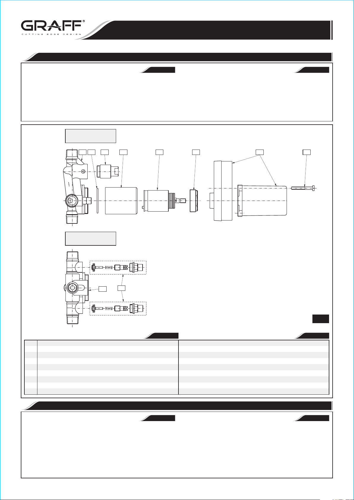
SIDE VIEW
VISTA LATERAL
R1 R2R3 R4
SHR
HOT
TUB
TOP VIEW
VISTA DELANTERA
El sistema de la ducha está conforma a los estándares de los E.E.U.U.: ANSI
A112.18.1 y ASSE 1016.
R5 R6 A
B
R1
R7
ENGLISH
BODY OF VALVE
R1
CAP
R2
O-RING SEAL
R3
CARTRIDGE COVER (SLEEVE)
R4
CARTRIDGE 1.57” (40mm) Pressure Balancing Cartridge
R5
NUT
R6
CHECK STOP VALVE
R7
PLASTER GUARD
A
PLASTER GUARD SCREWS
B
(2 PCS.)
INSTALLATION OF THE ROUGH VALVE ONLY INSTALACIÓN DE LA VÁLVULA DE EMPOTRADO
ENGLISH
CAUTION: Turn off water at main supply.
NOTE: If using a hand shower in place of a tub spout, pipe hand shower to
SHR outlet, and shower head to TUB outlets.
Disregard this, if tub spout is used.
2
~
ESPANOL
CUERPO DEL VÁLVULA
TAPÓN
SELLADOR DEL ANILLO
PROTECCIÓN DEL CARTUCHO
CARTUCHO 1.57” (40mm) Cartucho Equilibrante de la Presión
TUERCA
VÁLVULA DE RETENCIÓN
PROTECTOR DEL YASO
TORNILLOS DE PROTECTOR DEL YASO
CUIDADO: Desconecte el agua de la alimentación.
NOTA: Al usar la la ducha en vez del caño de la bañera, una la ducha de
mano con la salida de ducha, y el cabezal de la ducha con las salidas
de la BAÑERA.
No lo tome en cuenta al usar el caño de la bañera.
(2 PIÉZAS)
~
ESPANOL
To assure proper positioning in relation to wall, note roughing-in
dimensions on FIG. 3 and MIN.-MAX. label on plaster guard.
IOG 2258.98A
Para asegurar el bien posicionamiento en la pared consulte las
dimensiones de empotrado en la FIG. 3 y la etiqueta MIN.-MAX. en el
protector.
2
Rev. 4 August 2016
Page 3

PRESSURE BALANCE TUB & SHOWER
LA DUCHA CON GRIFO DE TINA EQUILIBRANTE DE LA PRESIÓN
This product complies with NSF61/9, ASME/ANSI A112.18.1
and CSA B 125 Standards.
Este se encuentra conforme con losestandares de NSF61/9,
producto
de ASME/ANSI A112.18.1 y de CSA B 125.
Installation Instructions Instrucciones de Instalación
SEE FIG. 2
Before installation, remove all referenced items starting with (B), (A),
(R7), (R6), (R5), (R4), (R3) and (R2).
Use thread sealant or Teflontape on threaded water connections. DO NOT
USE THREAD SEALANT OR TEFLON TAPE ON (R7), (R6), (R4) and
(R2). Make note, cold (C) water inlets are on the right, the hot (H) water
inlets are on the left, and the shower (SHR) outlets is pointing up facing
the installer.
For proper installation, the finished wall must be within the side wall of the
plaster guard markings.
Connections are:
1/2" copper sweat inlets for sweat inlets
1/2" male NPT for threaded inlets
Use adapters where needed, connect water inlets. Make sure all water
lines are secure.
Special Note: Secure and level valve before proceding.
Connect RIGID shower riser pipe and RIGID tub filler pipe. Make sure
piping is secure.
When finished soldering and the valve is cool, flush valve body. Then
replace all referenced items in reverse order: (R2), (R3), (R4), (R5),
(R6) both CHECK STOPS (R7), (A) and (B).
Cap or plug outlets and test set-up for leaks.
Upon completion of pressure testing, manufacture recommends that
(R7), hot and cold CHECK STOPS, be closed at this time by using a flatbladed screwdriver and fully turning the screws clockwise and installing
(A), PLASTER GUARD.
VER LA FIG. 2
Antes de la instalación quite todos los elementos de referencia empezando
por (B), (A), (R7), (R6), (R5), (R4), (R3) y (R2).
Aplique un sellador de roscas o una cinta de teflón en las conexiones
roscadas de agua. NO UTILICE SELLADOR DE ROSCAS NI CINTA DE
TEFLÓN EN (R7), (R6), (R4) y (R2). Preste atención en que las
entradas del agua fría (C) están a la derecha, las entradas del agua
caliente (H) están a la izquierda y la salida de la ducha (SHR) está en el
centro enfrente del montador.
Para la instalación correcta la pared de acabado debe debe encontrarse
por el lado de las marcaciones del protector.
Tipos de conexiones:
1/2" mando del grifo de cobre para grifos
1/2" rosca de briggs macho para entradas roscadas
Use adaptadores donde sean necesarios, conecte las entradas de agua.
Asegúrese de que las líneas de agua están seguras.
Nota especial: Asegure y nivele la válvula antes de seguir.
Conecte el tubo vertical RÍGIDO de la ducha y el tubo RÍGIDO del caño de
la ducha. Asegúrese de que la tubería está segura.
Después de terminar el soldado y cuando la válvula esté fría, enjuague el
cuerpo de la válvula. Luego vuelva a poner todos los elementos de
referencia en el orden siguiente: (R2), (R3), (R4), (R5), ambas
VÁLVULAS DE RETENCIÓN (R6) (R7), (A) Y (B).
Tape u obture las salidas y compruebe si el conjunto no tiene fugas.
Para terminar el ensayo de presión el fabricante recmienda que se cierren
(R7), VÁLVULAS DE RETENCIÓN del agua caliente y fría usando el
destornillador plano, girando completamente los tornillos e instalando
(A), el PROTECTOR.
SHR
TUB
MIN. 1-1/2" (38mm)
MAX. 2-1/4" (57mm)
TEST CAP
TAPÓN DE PRUEBA
NOTE: Recommended depth for valve body in the wall is measured from
the center of the shower outlet to the finished wall surface and must be in
the range of 1-1/2” (38 mm) to 2-1/4” (57 mm).
FINISHED WALL
MAX.
MAX. ACAPADA DE LA PARED
MIN.
FINISHED WALL
MIN. ACAPADA DE LA PARED
PLASTER GUARD
PROTECTOR DEL YASO
Make sure the hot and cold CHECK STOPS are fully open while in use only,
do not use CHECK STOPS to reduce or restrict water flow.
NOTA: La profundidad recomendada para el cuerpo de la válvula en la
pared se mide desde el centro de la salida de la ducha hasta la superficie
de la pared de acabado, y debe caber dentro del rango de 1-1/2” (38 mm)
a 2-1/4” (57 mm).
Asegúrese de que las VÁLVULAS DE RETENCIÓN están completamente
abiertas durante el uso, no se deben usar VÁLVULAS DE RETENCIÓN para
reducir o limitar el flujo de agua.
HO
T
NOTE: When installing threaded nut over cartridge,
tighten down using only 14.76 ft/lbs of torque maximum.
NOTA: Al poner la tuerca en el cartucho, apriétela con
el torque máximo de 14.76 ft/lbs
IOG 2258.98A
TEST CAP
TAPÓN DE PRUEBA
3
3
Rev. 4 August 2016
Page 4

PRESSURE BALANCE TUB & SHOWER
LA DUCHA CON GRIFO DE TINA EQUILIBRANTE DE LA PRESIÓN
This faucet complies with NSF61/9, ASME/ANSI A112.18.1
and CSA B 125 Standards.
Este grifo se encuentra conforme con losestandares de NSF61/9,
de ASME/ANSI A112.18.1 y de CSA B 125.
TRIM INSTALLATION INSTALACIÓN DE LA MOLDURA
Installation Instructions Instrucciones de Instalación
SHR
SHR
TUB
TUB
Finished wall
Acapada de la pared
Finished wall
Acapada de la pared
A1 A3
BA2
HO
T
R1
4.1
Finished wall
Acapada de la pared
T4
SHR
HO
T
R4R2T1
TUB
HO
T
SHR
HOT
TUB
R1 R4 R5 R6
Finished wall
Acapada de la pared
T4
4.2
R3
METAL SLEEVE
CASQUILLO METAL
SHR
HO
TUB
T
DECOR/COATED SLEEVE
CASQUILLO DECORATIVO
T4
R1
4.3
T6T5 T7 T8 T9
T2T1 T3 T10 T12
R1 R5 R6T1
4.4
T11
K
4.5
IOG 2258.98A
Rev. 4 August 2016
Page 5

PRESSURE BALANCE TUB & SHOWER
LA DUCHA CON GRIFO DE TINA EQUILIBRANTE DE LA PRESIÓN
This faucet complies with NSF61/9, ASME/ANSI A112.18.1
and CSA B 125 Standards.
Este grifo se encuentra conforme con losestandares de NSF61/9,
de ASME/ANSI A112.18.1 y de CSA B 125.
See fig. 4.1-4.5 Vea dis. 4.1-4.5
When wall treatment is complete remove screws (B) and black plaster guard Cuando el tratamiento de la pared este completo quite los tornillos (B) y el
(A) and discard. Unscrew a nut (R6) and take out a cartridge (R5). Unscrew protector negro del yaso (A) luego deseche. Abra la tuerca (R6) y meta el
metal sleeve (R4). In its place turn the decor/coated sleeve (T1), make sure cartucho (R5). Destornille el casquillo de metal (R4). En su lugar ponga el
that the o-ring seal (R3) is in correct position on the valve body (R1). Tighten casquillo decorativo (T1), asegúrese si la empaquetadura de o-ring (R3) se
the décor sleeve (T1) until clear resistance is felt. Insert the cartridge (R5) into halla en el cuerpo de válvula (R1). Atornille más el casquillo decorativo (T1)
the decor sleeve (T1), so that appropriate stubs in the lower part of the de modo que las buzas de la parte inferior del cartucho entren en los agujeros
cartridge fit into corresponding holes in the valve seat in valve body (R1). Make correspondientes del nido del cuerpo de la válvula (R1). Asegúrese si la
sure that the seat in the valve body is free from debris. Secure the nut (R6)
using torque of 10 Nm (7.38 ft lbs). Unscrew a plug (R2) using adjustable
wrench. In its place turn the diverter switch (T4) in. Use the adjustable wrench,
grip the diverter switch (T4) with the wrench in a place where special flats are.
Secure the diverter switch carefully) in order to avoid the decor damage at the
diverter sleeve finish. Tighten up the diverter switch (T4) until you feel
noticeable resistance.
Now you are ready to assemble the remaining decor items of the trim set.
Place two hole plate with seal (T5) inside. Push onto elongation (T2) and Después empiece el montaje de los restantes elementos decoraticos.
attach screw (T3). Screw the valve cover (T10) onto the valve body, install Coloque la placa de dos agujeros con la empquetadura interior. Coloque
handle (T11*) into valve and tightening set screw (T12). Push diverter knob en el alargamiento (T2) y coloque el tornillo (T3). Atornille la de la
(T6) onto diverter stem and attach with washer (T7) and nut (T8), fix diverter válvula (T10) sobre el cuerpo de válvula, instale la manilla (T11*) en la
cap (T9). válvula ajustando el tornillo de presión (T12).
* - Handle depends on series also see fig. 2A, 2B
TEMPERATURE LIMITING DEVICE LIMITADOR DE TEMPERATURA
The red ring (item A fig. 5.1) around the thermostatic cartridge allows the El anillo rojo (punto A dis. 5.1) alrededor del cartucho termostático limita la
maximum output temperature to be limited in order to avoid the accidental temperatura máxima del agua de salida con el fin de evitar quemaduras
scalding. The ring is factory pre-set to the highest setting allowing the greatest casuales. El anillo está preajustado en la fabrica para permitir la salida del
flow of hot water. Adjust the temperature so that it does not exceed flujo máximo de agua caliente. Ajustar la temperatura para que no
0 0 0 0
49 C (120 F). supere los 49 C (120 F).
Installation Instructions Instrucciones de Instalación
ENGLISH
superficie del nido de cartucho en el cuerpo de la válvula y las juntas en el
cartucho están limpias. Atornille la tuerca (R6) usando el momento
10 Nm (7.38 ft lbs). Destornille el tapón (R2) usando la llave inglesa. En
su lugar atornille el conmutador de válvula (T4). Use la llave inglesa, tome
con la llave inglesa el conmutador (T4) en el lugar donde hay unos planos
especiales de la llave. Atornille cautelosamente para no estropear el
acabado decorativo de la protección del cartucho. Atornille el conmutador
(T4) hasta el momento de sentir una resistencia clara.
(T5)
Coloque la bola del desviador (T6) sobre el desviador y fije con la arandela
(T7) y la tuerca (T8), coloquela cubierta del desviador (T9).
* - Las manillas dependen de la serie vea tambien fig. 2A, 2B
ENGLISH
~
ESPANOL
cubierta
~
ESPANOL
ADJUSTMENT OF TEMPERATURE LIMITING DEVICE AJUSTE DEL LIMITADOR DE TEMPERATURA
~
See fig. 4.5, 5.1-5.3 Vea dis. 4.5, 5.1-5.3
In order to adjust the maximum desired temperature, the following procedure Para ajustar la temperatura máxima deseada, hay que realizar los siguientes
should be carried out on the cartridge and the ring (A): pasos con el cartucho y el anillo (A):
the valve should be in “Off” position, la válvula debe estar en la posición “Off”;
remove the handle (item T11* fig. 4.5), valve cover (T10), quitar la manilla (punto T11* dis. 4.5), la cubierta de la válvula (T10);
remove the red ring (A) from the cartridge by pulling it away, quitar el anillo rojo (A) del cartujo tirándolo hacia afuera;
rotate the ring clockwise and put it back onto the cartridge – align the girar el anillo en la dirección del reloj y colocar de nuevo sobre el
notch (dot) on the blue cartridge body with one of the lines of the scale on cartucho – alinear la entalla (punto) en el cuerpo azul del cartucho con
the ring between and – signs – see fig. 5.2 & 5.3; una de las líneas en la escala del anillo entre los signos de y ;
put the handle (T11*) onto the valve and rotate it fully anticlockwise vea el dibujo 5.2 y 5.3;
turning the water on, colocar la manilla (T11*) sobre la válvula y girarla completamente en la
check if the temperature of water is correct if not, change the position of dirección opuesta al movimiento del reloj, abriendo la salida del agua;
the red ring (A). verificar si la temperatura del agua está correcta – si no lo está,
reassemble the valve cover (T10) and the handle (T11*). cambiar la posición del anillo rojo (A);
ENGLISH
colocar de nuevo la cubierta de la válvula (T10) y la manilla (T11*);
ESPANOL
5.1 5.2 5.3
B
SHR
HO
T
TUB
A
D
C
A
D
B
C
A - Temperature Limiting Ring
B - Limiting blocks of the cartridge
C - Indicator of position of temperature limit
D - Limiting Scale
IOG 2258.98A
A
Factory preset position –
Max flow of hot water
Posición preajustada en la fabrica –
flujo máximo del agua caliente
A - Anillo limitador de temperaturas
B - Limitadores en el cartucho
C - Indicador de la posición del limite de temperatura
D - Escala de limitación
Flow of hot water limited
to desired temperature
Flujo del agua caliente limitado
a la temperatura deseada
Rev. 4 August 2016
Page 6

LA DUCHA CON GRIFO DE TINA EQUILIBRANTE DE LA PRESIÓN
This product complies with NSF61/9, ASME/ANSI A112.18.1
and CSA B 125 Standards.
Este se encuentra conforme con losestandares de NSF61/9,
producto
de ASME/ANSI A112.18.1 y de CSA B 125.
OPERATING INSTRUCTIONS DESCRIPCIÓN DEL FUNCIONAMIENTO
ENGLISH
The water flow is opened and water temperature is set using the lever or
the handle. It is opened fully by turning the lever in counter-clockwise
direction. The water temperature is regulated by positioning the lever
within the range from the “Off “ position through the “Cold” to the “Hot”
with max temperature.
During normal mode of operation the water is directed to the spout;
pressing of the diverter knob redirects the water flow to the shower head.
After turning the water off the diverter knob returns to the initial position
(normal mode).
CARE AND MAINTENANCE CUIDADO Y MANTENIMIENTO
ENGLISH
Your Graff product is designed and engineered in accordance with the highest
quality and performance standards. Be sure not to damage the finish during
installation. Care should be given to the cleaning of this product. Although its
finish is extremely durable, it can be damaged by harsh abrasives or polish.
Never use abrasive cleaners, acids, solvents, etc. to clean any Graff
product. To clean, simply wipe gently with a damp cloth and blot dry
with a soft towel.
Installation Instructions Instrucciones de Instalación
PRESSURE BALANCE TUB & SHOWER
~
ESPANOL
Para abrir la salida y de ajuste de temperatura sirve la palanca o la llave.
Obtenemos la apertura completa girando la palanca en la dirección
opuesta al movimiento del reloj. La regulación del agua que sale se
efectúa entre la posición “Off”, pasando por la posición “Cold”, hasta la
posición “Hot” de la temperatura máxima.
Normalmente el agua va dirigida al cańo; empujando la perilla dirigimos el
agua al cabezal de la ducha. Al cerrar el agua, la perilla regresa
automáticamente a la posición normal (inicial).
~
ESPANOL
Su producto de la Graff está diseñado y dirigido acuerdo con los estándares de
funcionamiento y calidad más altos. Este seguro no dañar las terminaciones
del grifo durante la instalación. Cuide el producto manteniendolo siempre
limpio. Aunque su acabado es extremadamente durable, puede ser dañado
por los abrasivos o pulientes ásperos. Nunca utilice limpiadores
abrasivos, ácidos, solventes, etc. para limpiar cualquier producto de
la Graff. Para limpiar, simplemente use un paño húmedo y seque con
una toalla suave.
ENGLISH
Warranty conditions and warranty registration card are outlined on a
separate sheet.
WARRANTY GARANTÍA
~
ESPANOL
Las condiciones de la garantía y la tarjeta del registro de la garantía se
encuentran en una pagina separada.
IOG 2258.98A
6
Rev. 4 August 2016
 Loading...